FANUC Series 30i-MODEL B, 31i-MODEL B, 32i-MODEL B. MAINTENANCE MANUAL - page 9
2.CONTROL UNIT HARDWARE
B-64485EN/01
-
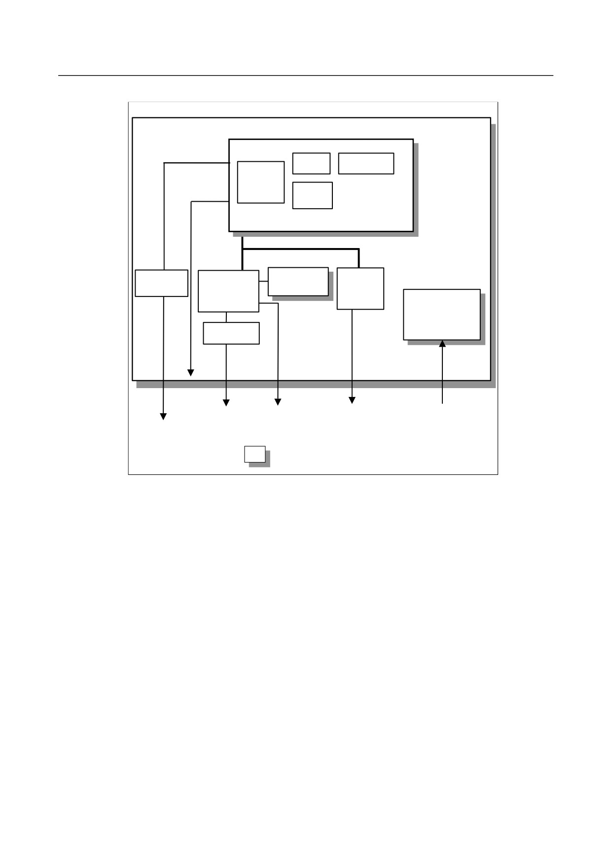
Block diagram
Display control board
GUI card
DRAM
Display control
CPU
BOOT
software
Ethernet
Compact
Peripheral
Peripheral
Flash card
control
control 1
control 2
Power supply unit
USB control
Display
unit
RS-232C
HSSB
24VDC
USB
Memory
Ethernet
card
: Detachable card or module
- 222 -
B-64485EN/01
2.CONTROL UNIT HARDWARE
-
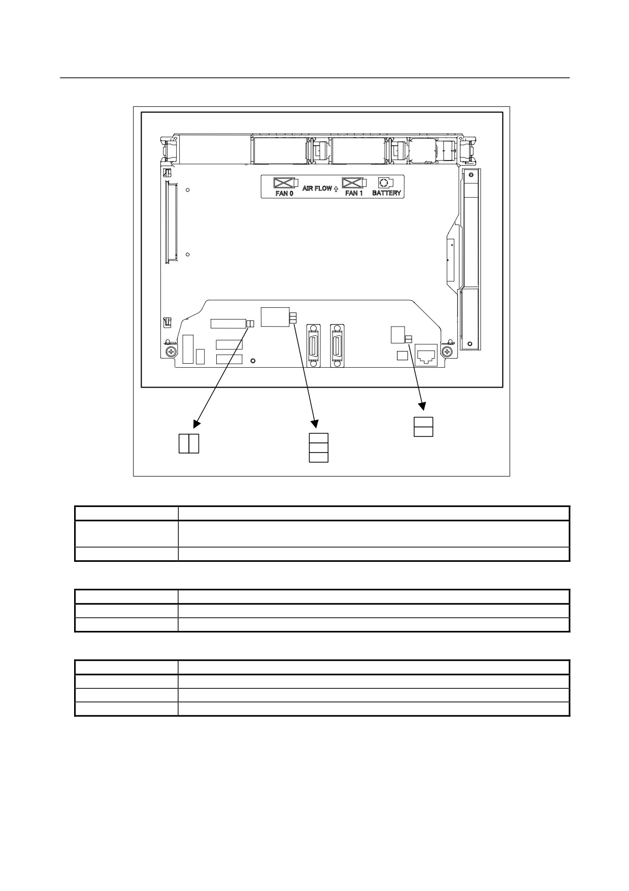
LED display
Rear view
LINK(green)
COM(yellow)
ALM2
BSRDY
DNV8(green)
(red)
(green)
DNV9(green)
DNV5(green)
(1) HSSB status
LED
Meaning
Lights when this board is normally connected to the control unit and communication is
BSRDY (green)
enabled.
ALM2 (RAME ⋅ red)
Indicates a common RAM error. It is likely that the display control board may be defective.
(2) Ethernet status
Name
Meaning
LINK (green)
Turned on when a connection is made with the hub correctly.
COM (yellow)
Turned on when data is transferred.
(3) Others (green LED)
Name
Meaning
DNV5 (LEDP)
Turned on when power is supplied to the GUI card.
DNV8 (LED2)
Indicates the operation status of the personal computer function.
DNV9 (LED1)
Indicates the operation status of the personal computer function.
- 223 -
2.CONTROL UNIT HARDWARE
B-64485EN/01
-
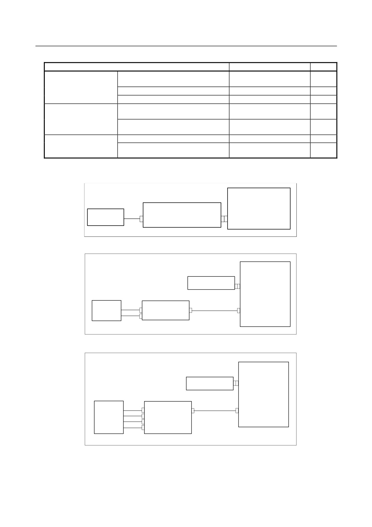
Specifications of Inverter board and fan adapter board
Name
Specification
Remark
Inverter board
For 10.4” LCD (working also as fan adapter
A20B-8200-0662
board)
For 12.1” LCD
A14L-0143-0003
For 15” LCD
A14L-0168-0001
㪝㪸㫅㩷㪸㪻㪸㫇㫋㪼㫉㩷㪹㫆㪸㫉㪻
For 10.4” LCD (working also as fan adapter
Works also as the inverter
board)
board mentioned above.
For 12.1” LCD
A20B-8200-0669
For 15” LCD
㪚㫆㫅㫅㪼㪺㫋㫀㫆㫅㩷㪺㪸㪹㫃㪼㩷㪹㪼㫋㫎㪼㪼㫅㩷㫋㪿㪼㩷For 12.1” LCD
A660-4042-T075#L90R00
㪻㫀㫊㫇㫃㪸㫐㩷㪺㫆㫅㫋㫉㫆㫃㩷㪹㫆㪸㫉㪻㩷㪸㫅㪻㩷㫋㪿㪼㩷
For 15” LCD
A660-4042-T076#L75R00
㫀㫅㫍㪼㫉㫋㪼㫉㩷㪹㫆㪸㫉㪻
-
Details of the inverter board
(1) For display unit with 10.4” LCD
Display control board
Inverter board
10.4”LCD unit
(Also functions as a fan adapter board.)
CA132
CP1
CN1
(2) For display unit with 12.1” LCD
Display control board
Fan adapter board
CA132
CN1
12.1”LCD unit
Inverter board
CA134
CN2
CN1
Inverter connection cable
CN3
(3) For display unit with 15” LCD
Display control board
Fan adapter board
CA132
CN1
15”LCD unit
Inverter board
CA134
CN02
CN01
Inverter connection cable
CN03
CN04
CN05
- 224 -
B-64485EN/01
2.CONTROL UNIT HARDWARE
-
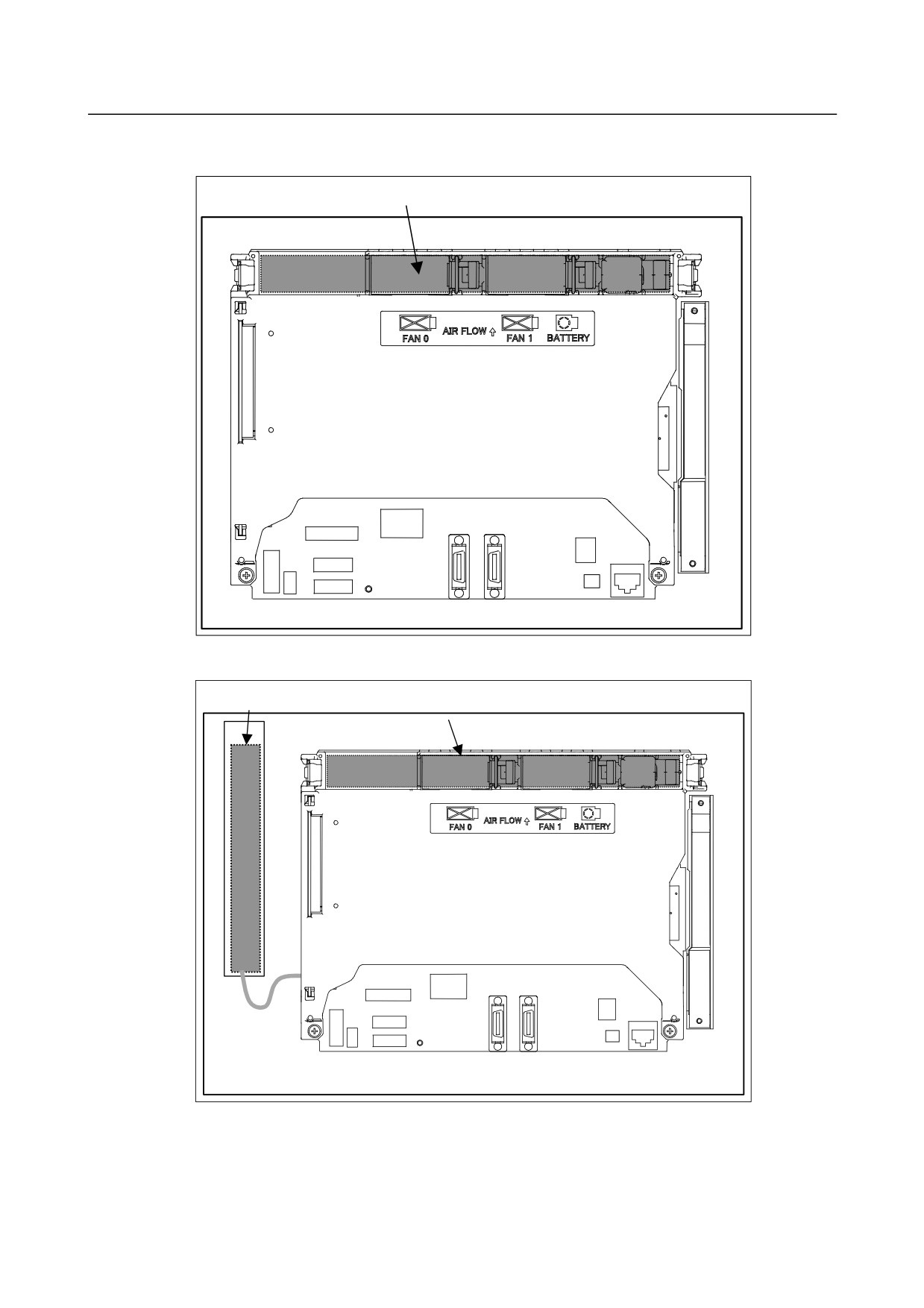
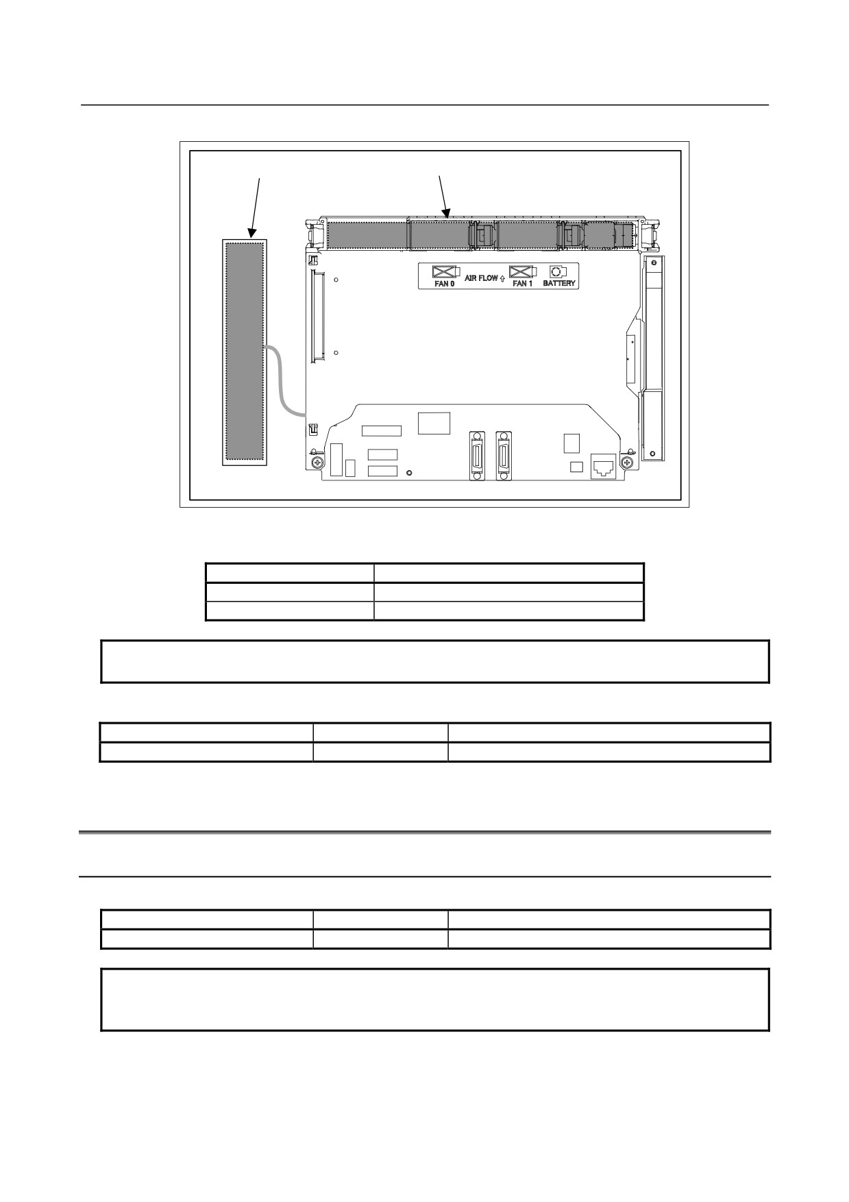
Locations of the inverter board and fan adapter board
(1) For display unit with 10.4” LCD
Inverter board
Rear view
(2) For display unit with 12.1” LCD
Inverter board
Fan adapter board
Rear view
- 225 -
2.CONTROL UNIT HARDWARE
B-64485EN/01
(3) For display unit with 15” LCD
Inverter board
Fan adapter board
Rear view
-
Connecting the display unit to the control unit
For the display unit, place the rotary switch to 0 (initial setting).
Connection mode
Rotary switch setting
Default
0
Reserve
1 to F
NOTE
Do not set the rotary switch to the Reserve position.
-
Backup unit specification
Name
Specification
Remark
Backup board
A20B-2100-0820
See Subsection 2.4.3, “Bacuup Unit”.
2.6
HARDWARE OF OPTIONAL BOARDS
2.6.1
Fast Ethernet Board
-
Specification
Name
Specification
Remark
Fast Ethernet board
A20B-8101-0770
NOTE
The Ethernet board may be used for the data server and FL-net functions as well
as the Ethernet functions depending on parameter setting.
- 226 -
B-64485EN/01
2.CONTROL UNIT HARDWARE
-
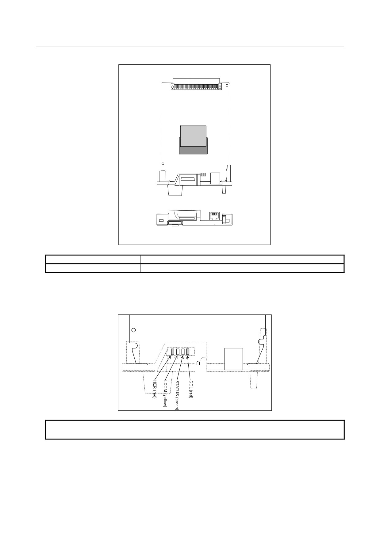
Connector mounting location
Compact
flash card
CD38R
Connector number
Application
CD38R
For Ethernet
-
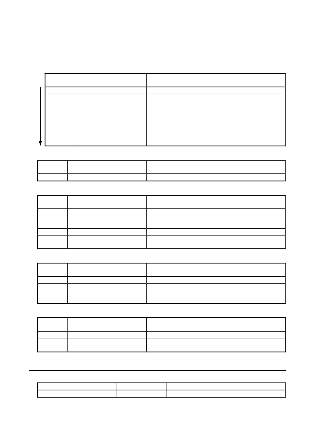
LED display
The board incorporates four LEDs.
The locations and meanings of the LEDs are indicated below.
CD38R
NOTE
The face plate is indicated with dotted line.
- 227 -
2.CONTROL UNIT HARDWARE
B-64485EN/01
In the following explanations, the LED lighting states are expressed as follows:
□: Off
■: On
☆: Blinking
LED display transition for STATUS (power on state)
LED
Status
Meaning
display
□
Power-off
■
Immediately after power-on
Initial state entered immediately after power-on.
If the board is stopped in this condition, the cause is one of the
following:
→ The CNC communication software may not be running
normally. Check whether the communication software is
installed properly.
→ The hardware may be faulty. Replace this board.
☆
Start completion
The board has started normally.
LED display transition for STATUS (during normal operation)
LED
Status
Meaning
display
☆
Normal status
The board is operating normally.
LED display for LCOM
LED
Status
Meaning
display
□
Not connected to hub
The board is not connected to the hub properly.
The LED stays off also when the power to the hub is off.
Check whether the board is connected to the hub properly.
■
Connected to hub
The board is connected to the hub.
☆
Transmission/reception in
Data is being transmitted or received.
progress
LED display for COL
LED
Status
Meaning
display
□
Normal status
The board is operating normally.
■
Collision occurs.
The LED is on or blinks at short intervals when the Ethernet
☆
(Data collision occurs.)
communication traffic (communication amount) is high or
ambient noise is high.
LED display for HER
LED
Status
Meaning
display
□
Normal status
The board is operating normally.
■
Error detected in the hardware
The cause may be a failure in this board or a malfunction due
☆
Error detected in the software
to noise.
2.6.2
Additional axis board
-
Specification
Name
Specification
Remark
Additional axis board
A20B-8101-0740
- 228 -
B-64485EN/01
2.CONTROL UNIT HARDWARE
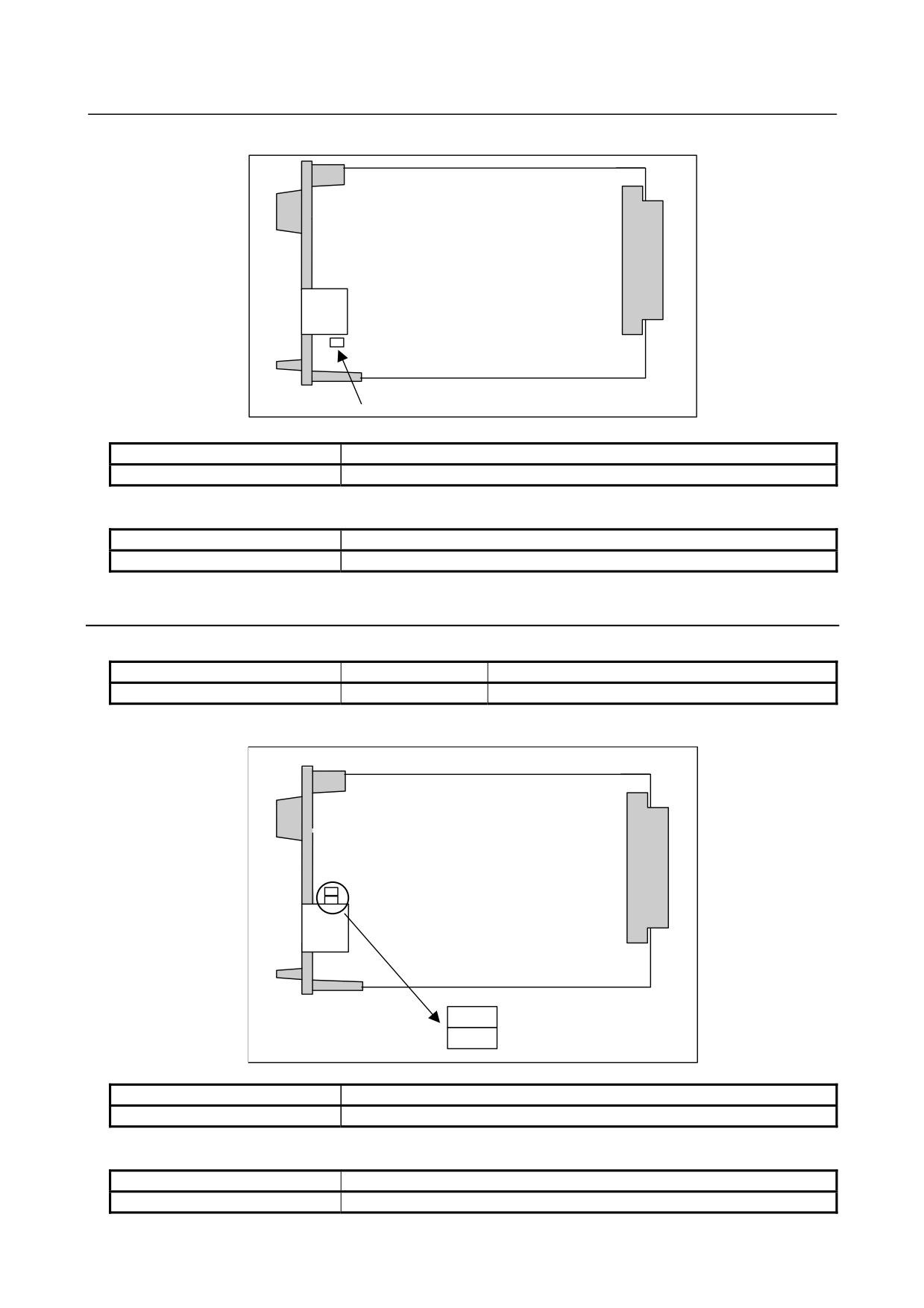
Connector and LED mounting location and LED display
COP10A
FSSB_OP (green)
Connector number
Application
COP10A
For FSSB interface
-
LED display
LED
Meaning
FBBS_OP (green)
ON: FSSB connected
2.6.3
HSSB interface board
-
Specification
Name
Specification
Remark
HSSB interface board
A20B-8101-0111
-
Connector and LED mounting location and LED display
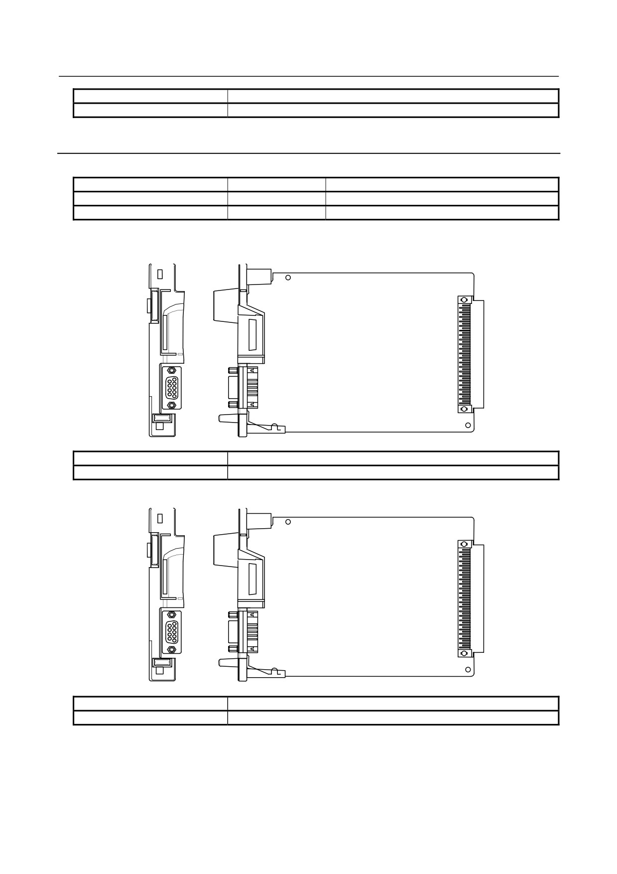
LEDR
(red)
BRDYA
(green)
Connector number
Application
COP21N
For HSSB interface
-
LED display
LED
Meaning
LEDR
Turned on when a common RAM parity error occurs in this board.
- 229 -
2.CONTROL UNIT HARDWARE
B-64485EN/01
LED
Meaning
BRDYA
Lights to indicate that a link has been established.
2.6.4
PROFIBUS-DP Board
-
Specification
Name
Specification
Remark
PROFIBUS-DP master board
A20B-8101-0050
PROFIBUS-DP slave board
A20B-8101-0100
Connector mounting location
-
PROFIBUS-DP master board
CN1
Connector number
Application
CN1
For PROFIBUS-DP master interface
-
PROFIBUS-DP slave board
CN2
Connector number
Application
CN2
For PROFIBUS-DP slave interface
- 230 -
B-64485EN/01
2.CONTROL UNIT HARDWARE
-
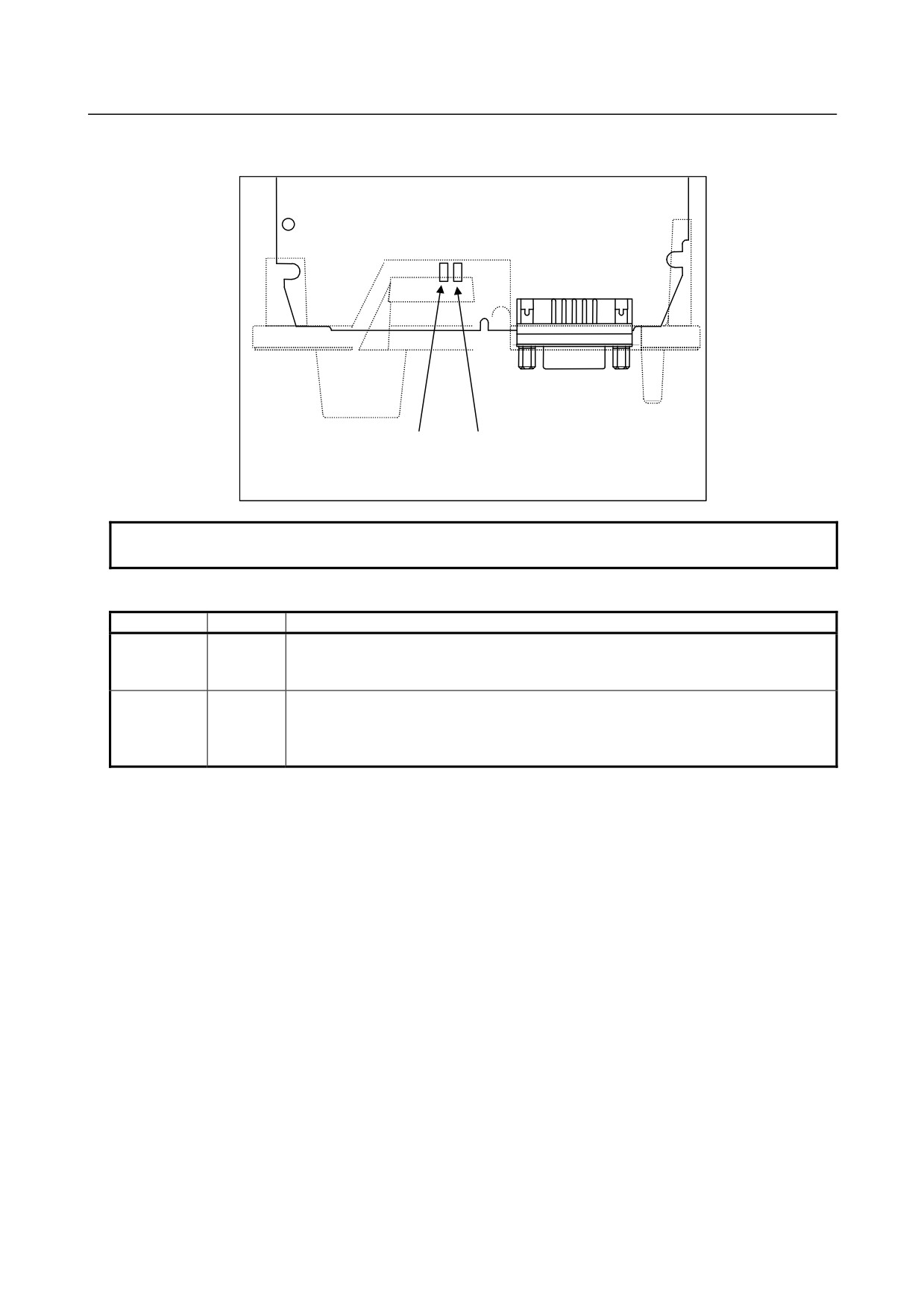
LED display and their meanings
-
PROFIBUS-DP master interface
CN1
㪣㪜㪛㪉
㪣㪜㪛㪈
NOTE
The face plate is indicated with dotted line.
-
LED display
Name
Color
Description
Indicates that the CPU on this board has started running.
LED1
Green
On: RESET has been released, allowing the CPU to start running.
The LED is turned off when the power is turned on.
Indicates whether communication is being normally carried out.
On: Communication is being normally carried out.
LED2
Green
Off: Communication is not being carried out.
The LED is turned off when the power is turned on.
㩷
- 231 -
2.CONTROL UNIT HARDWARE
B-64485EN/01
-
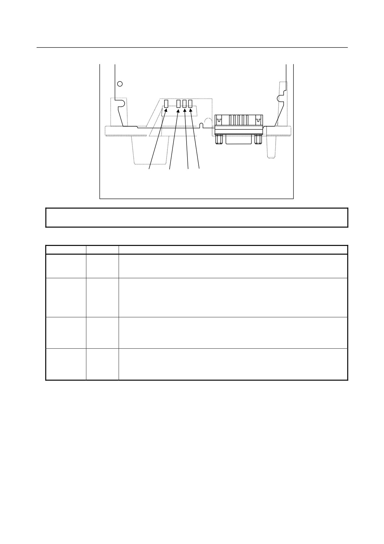
PROFIBUS-DP slave board
CN2
㪣㪜㪛㪙㩷 㪣㪜㪛㪊 㪣㪜㪛㪉 㪣㪜㪛㪈
NOTE
The face plate is indicated with dotted line.
-
LED display
Name
Color
Description
Indicates that the CPU on this board has started running.
LED1
Green
On: RESET has been released, allowing the CPU to start running.
The LED is turned off when the power is turned on.
Indicates that communication has started.
On: Communication has started.
LED2
Green
The LED is turned off when the power is turned on or if:
-
No parameter data and configuration data have been received.
-
Invalid parameter data and configuration data have been received.
Indicates whether communication is being normally carried out.
On: Communication is being normally carried out.
LED3
Green
Off: Communication is not being carried out.
The LED is turned off when the power is turned on.
Indicates that a RAM parity alarm condition has occurred on this board.
On: A RAM parity alarm condition has occurred.
LEDB
Red
The LED is turned off when the power is turned on. Once it has been turned on, it
stays on until the power is turned off.
- 232 -
B-64485EN/01
2.CONTROL UNIT HARDWARE
2.6.5
DeviceNet Board
Specification
Name
Specification
Remark
DeviceNet master board
A20B-8101-0220
DeviceNet slave board
A20B-8101-0330
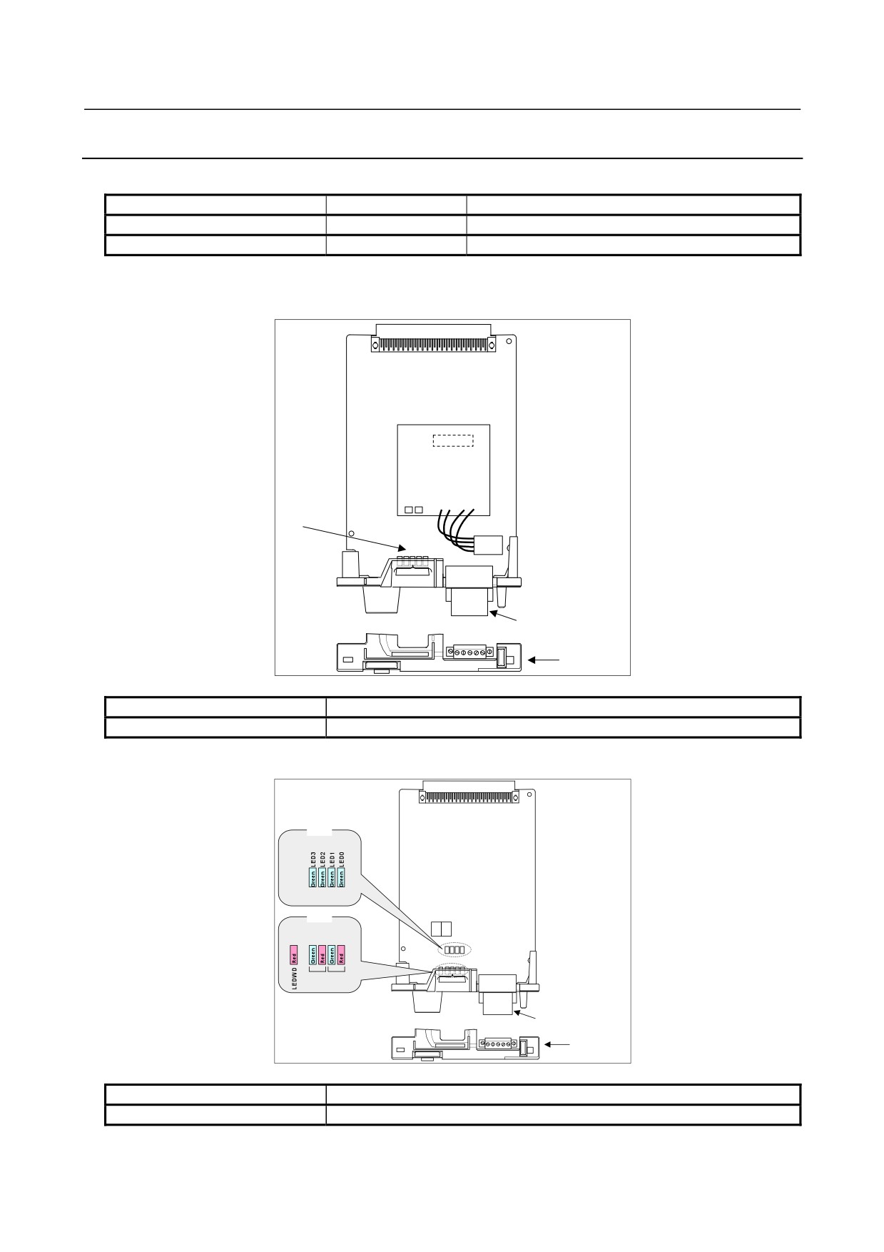
Connector and LED mounting location
-
DeviceNet master board
Daughter board
From left to
right
LEDWD
LED3
NS MS (LED)
LED2
LED1
LED0
TBL
Face plate
Connector number
Application
TBL
For DeviceNet interface
-
DeviceNet slave board
LED
LED
MS NS
TBL
Face plate
Connector number
Application
TBL
For DeviceNet interface
- 233 -
2.CONTROL UNIT HARDWARE
B-64485EN/01
LED display and their meanings
-
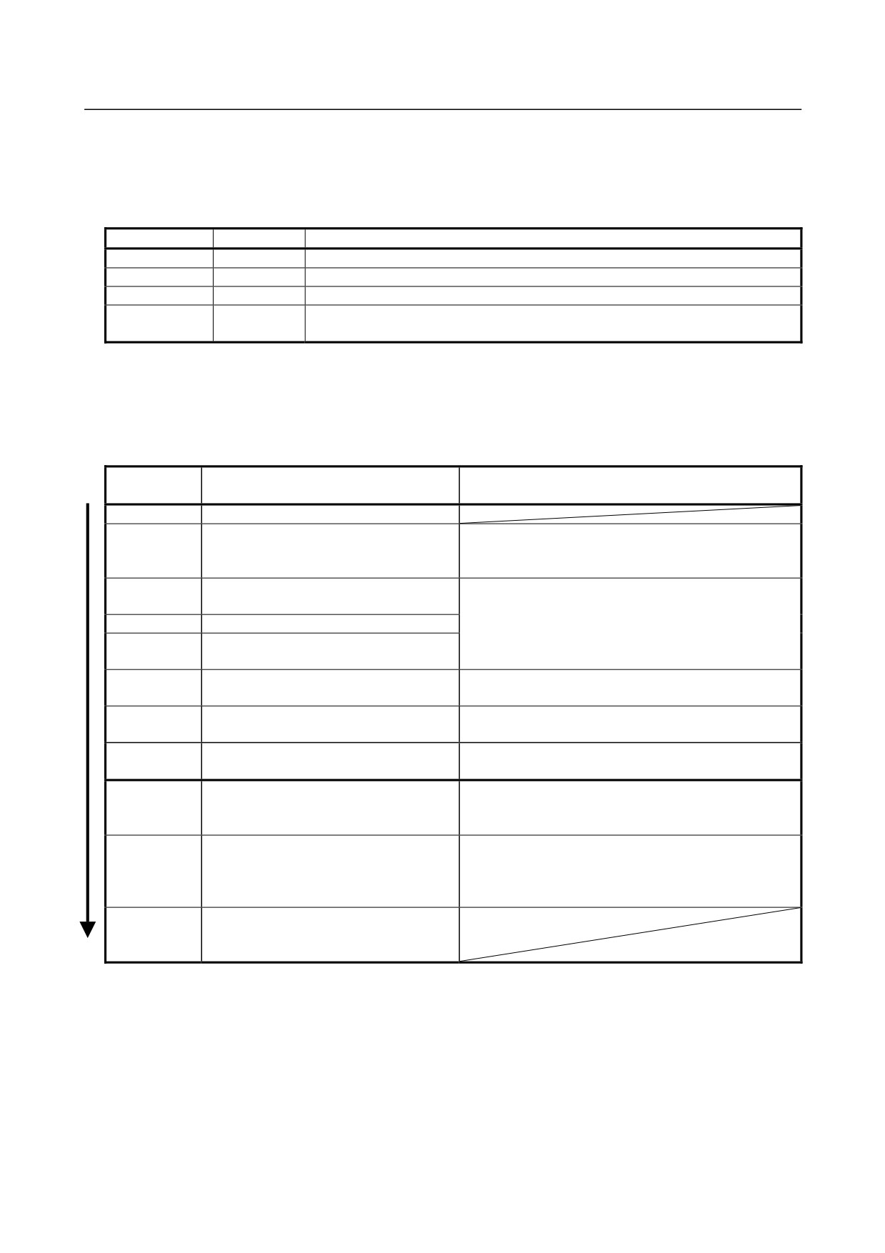
DeviceNet master board
This board provides four green LEDs and one red LED for status indication. In addition, the internal
daughter board has two LEDs that emit red and green light.
Name
Color
Meaning
LED0 to 3
Green
Indicates the activation state of the DeviceNet application software.
LEDWD
Red
Indicates an error on the daughter board.
MS
Red / green
Indicates the module status, which is the status of the local node.
Indicates the network status, which is the status of the entire network including the
NS
Red / green
local node.
In the following explanations, the LED lighting states are expressed as follows:
□: Off
■: On
☆: Blinking
◇: Don’t care
LED display transition for LED0, LED1, LED2, and LED3 (during power-on)
LED
Status after power-on
Action when stopped after power-on
3 2 1 0
□□□□
Power-off
■■■■
After power-on, the DeviceNet application
The DeviceNet application software is not running
software does not start.
normally. Check whether the software is installed
properly.
□□□□
Initializing the firmware on the daughter
Replace the DeviceNet master board.
board.
□□□■
Checking memory on the daughter board.
□□■□
Recognizing the firmware on the daughter
board.
□□■■
Reading DeviceNet parameters.
Confirm that DeviceNet master function (software option)
has been purchased.
□■□□
Verifying that DeviceNet parameter
Set DeviceNet parameter “NETWORK” to “ONLINE.”
“NETWORK” is set to “ONLINE.”
□■□■
Setting the bus parameter in DeviceNet
Replace the DeviceNet master board.
parameters.
□■■□
Setting the slave parameter in DeviceNet
Set the slave parameter in DeviceNet parameters
parameters.
correctly. If there is no problem with the setting, replace
the DeviceNet master board.
□■■■
Checking duplicate MAC IDs.
Check duplication with the MAC ID of a slave device.
Check if cables are connected correctly.
Check if power for communication is correctly supplied.
Check if slave devices are turned on.
■□□□
The DeviceNet application software has
been initialized and I/O communication
starts.
- 234 -
B-64485EN/01
2.CONTROL UNIT HARDWARE
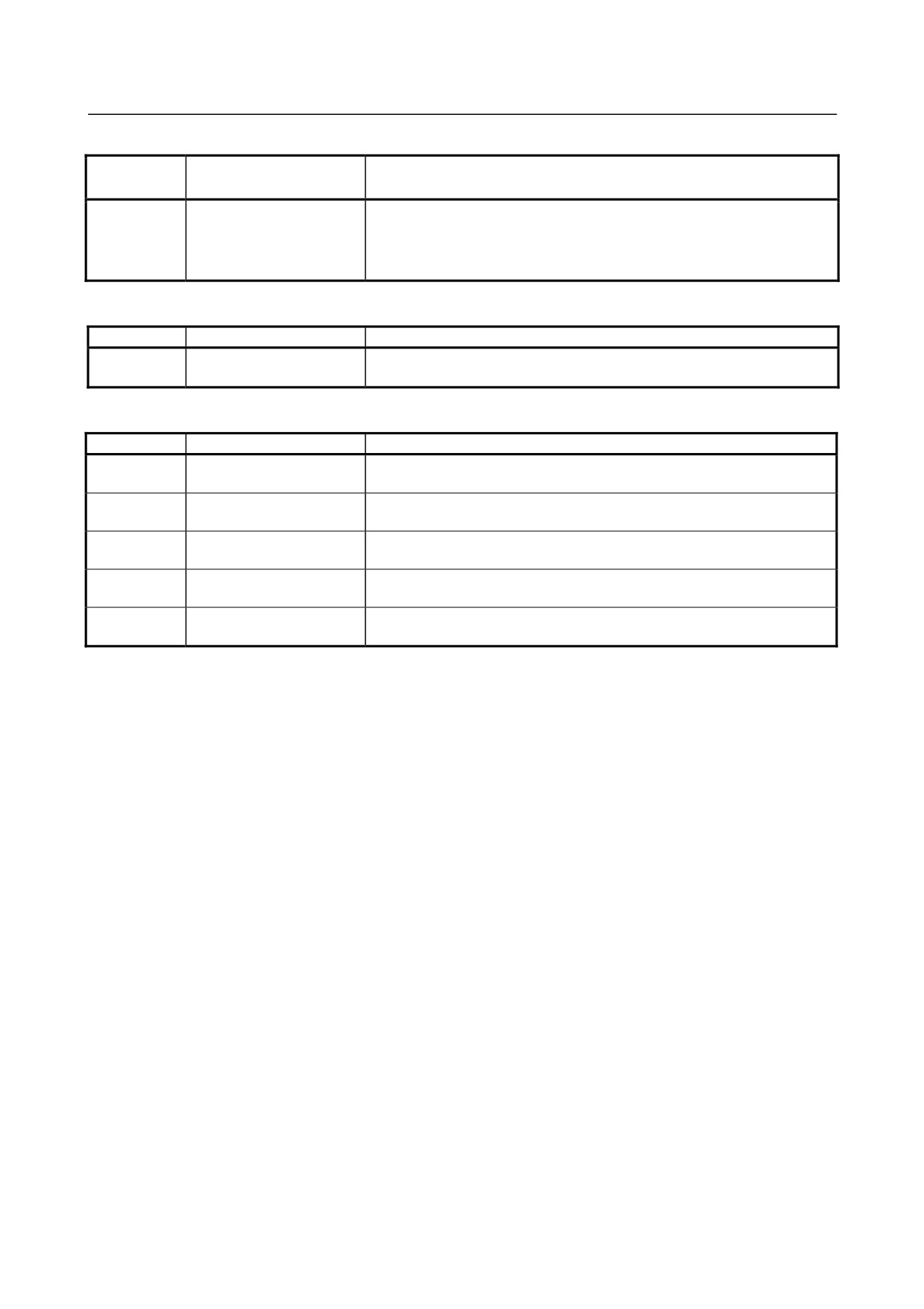
LED display for LED1, LED2, LED3, and LED4 (when abnormality occurs)
LED
Status
Meaning
3 2 1 0
□□□□
Daughter board failure
The daughter board failed.
↑↓
Replace the DeviceNet master board.
■■■■
(Repetition)
LED display for LEDWD
LED display
Status
Meaning
■
Daughter board failure
The daughter board failed.
Replace the DeviceNet master board.
LED display of MS and NS (during normal operation)
LED display
Status
Meaning
MS □
Immediately after power-on
The MPU on the daughter board is being reset.
NS □
MS ☆ green
Initializing
The firmware on the daughter board is making a initialization.
NS □
MS ■ green
Checking duplication of
The firmware on the daughter board is checking duplicated MAC IDs.
NS □
MAC IDs
MS ■ green
I/O communication stopped
The firmware on the daughter board is stopping I/O communication.
NS ☆ green
MS ■ green
I/O communication in
The firmware on the daughter board is successfully performing I/O
NS ■ green
advance
communication.
- 235 -
2.CONTROL UNIT HARDWARE
B-64485EN/01
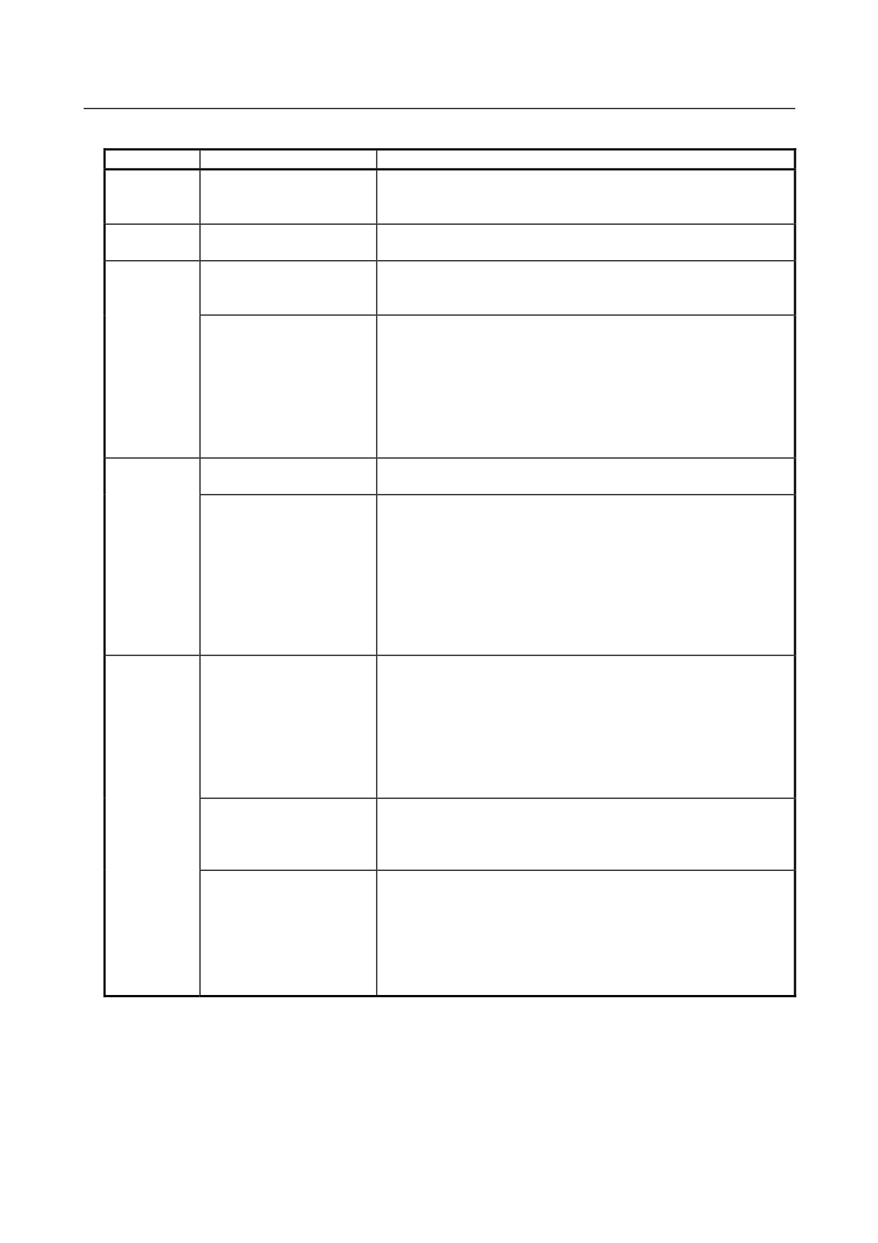
LED display of MS and NS (during occurrence of an error)
LED display
Status
Error and action
MS ☆ red
Daughter board failure
A MAC ID or communication rate setting error occurred or the
NS ◇
daughter board failed. When the setting is correct, replace the
DeviceNet master board.
MS ■ red
Daughter board failure
The daughter board failed.
NS □
Replace the DeviceNet master board.
MS ◇
Duplicate MAC IDs
MAC IDs are duplicate.
NS ■ red
Verify the following:
→ MAC IDs are not duplicate by check the MAC IDs of all nodes.
Busoff detection
Communication stopped because a communication error occurred
frequently.
Verify the following:
→ The communication rates of all nodes are set to the same value.
→ The cable length is appropriate.
→ The cable is not loose or broken.
→ A terminal is placed on only both ends of the main line.
→ There is not much noise.
MS ◇
Network power failure
Power for communication is not supplied. Verify the following:
NS □
→ Power for communication is properly supplied.
Transmission error
Transmission is not completed successfully.
Verify the following:
→ All slaves are turned on.
→ There is no other master on the network.
→ The communication rates of all nodes are set to the same value.
→ The cable length is appropriate.
→ The cable is not loose or broken.
→ A terminal is placed on only both ends of the main line.
→ There is not much noise.
MS ◇
Slave not present
No slaves are present.
NS ☆ red
Verify the following:
→ The slave is turned on.
→ The communication rates of all nodes are set to the same value.
→ The cable length is appropriate.
→ The cable is not loose or broken.
→ A terminal is placed on only both ends of the main line.
→ There is not much noise.
Slave I/O size mismatch
The slave I/O size setting does not match the setting of the actual
slave.
Verify the following:
→ The slave I/O size setting matches the setting of the actual slave.
I/O communication error
I/O communication timed out.
Verify the following:
→ The communication rates of all nodes are set to the same value.
→ The cable length is appropriate.
→ The cable is not loose or broken.
→ A terminal is placed on only both ends of the main line.
→ There is not much noise.
- 236 -
B-64485EN/01
2.CONTROL UNIT HARDWARE
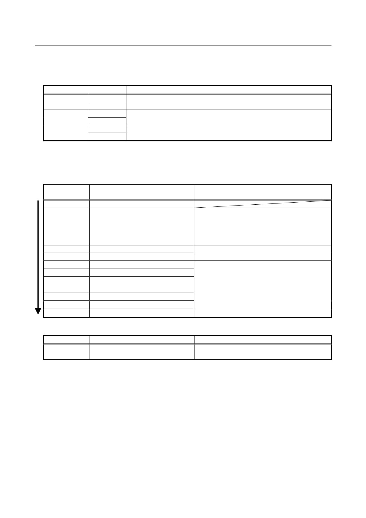
DeviceNet slave board
This board provides four green LEDs (LED0 to LED3) and one red LED (LEDWD) for status indication.
In addition, there are two LED sets (MS and NS) that consist of one red LED and one green LED.
Name
Color
Meaning
LED0 to 3
Green
Indicates the activation state of the DeviceNet application software.
LEDWD
Red
Indicates an error on the DeviceNet slave board.
Green
Indicates the module status, which is the status of the local node.
MS
Red
Green
Indicates the network status, which is the status of the entire network including the
NS
Red
local node.
In the following explanations, the LED lighting states are expressed as follows:
□: Off
■: On
☆: Blinking
◇: Don’t care
?:Undefined
LED display transition for LED0, LED1, LED2, and LED3
LED
Status and cause when stopped after
Action when stopped after power-on
3 2 1 0
power-on
□□□□
Power-off
■■■■
After power-on, the DeviceNet application
The DeviceNet application software is not running
software does not start. Or, the DeviceNet
normally. Check whether the software is installed
slave function (software option) is
properly.
disabled.
Or, confirm that the DeviceNet slave function (software
option) has been purchased.
□□□□
Initializing the firmware.
Replace the DeviceNet slave board.
□□□■
Firmware has been initialized.
□□■□
A line baud rate check is in progress.
Check the status of communication with the DeviceNet
□□■■
Checking duplication of MAC IDs
master.
□■□□
Waiting for I/O communication to be
A network power failure may also occur. Check
whether the power for communication is supplied
established.
properly.
□■□■
I/O communication is normal.
If the system does not recover from the error, replace
□■■□
I/O communication has timed out.
the DeviceNet slave board.
□■■■
I/O communication is idle.
LED display for LEDWD
LED display
Status
Meaning
■
Board failure
The DeviceNet slave board failed.
Replace the DeviceNet slave board.
- 237 -
2.CONTROL UNIT HARDWARE
B-64485EN/01
LED display of MS and NS (during normal operation)
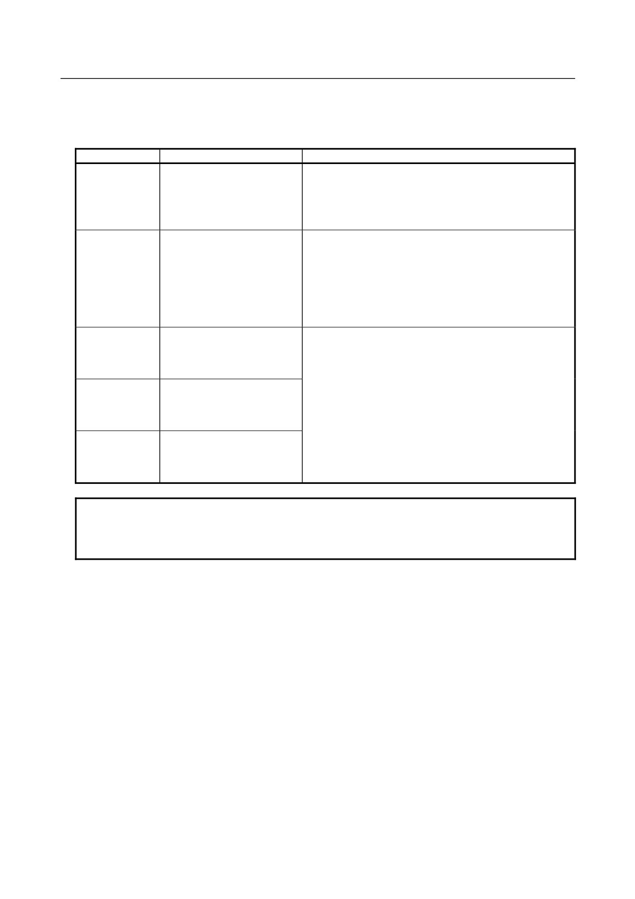
In the “during normal operation” status, when communication is normally established, a transition to the
“I/O communication normal” status is made.
LED display
Status
Meaning
MS □ green
Immediately after power-on
The onboard firmware is being initialized when the onboard
MS □ red
MPU is in the reset status or reset release status.
NS □ green
NS □ red
MS ■ green
Communication under
The onboard firmware performs processing in the order below.
MS □ red
preparation
(1) Waits for the DeviceNet application software to be
NS □ green
initialized.
NS □ red
(2) Checks the baud rate.
(3) Checks MAC ID duplication.
MS ■ green
Waiting for I/O communication to
Each status corresponds to DeviceNet MPU status transition.
MS □ red
be established.
NS ☆ green
NS □ red
MS ■ green
I/O communication is normal.
MS □ red
NS ■ green
NS □ red
MS ◇ green
I/O communication has timed
MS ◇ red
out.
NS ■ green
NS ☆ red
NOTE
When a transition to the "I/O communication normal" status is not made, confirm
that the power for communication is correctly supplied because a network power
failure may have occurred.
- 238 -
B-64485EN/01
2.CONTROL UNIT HARDWARE
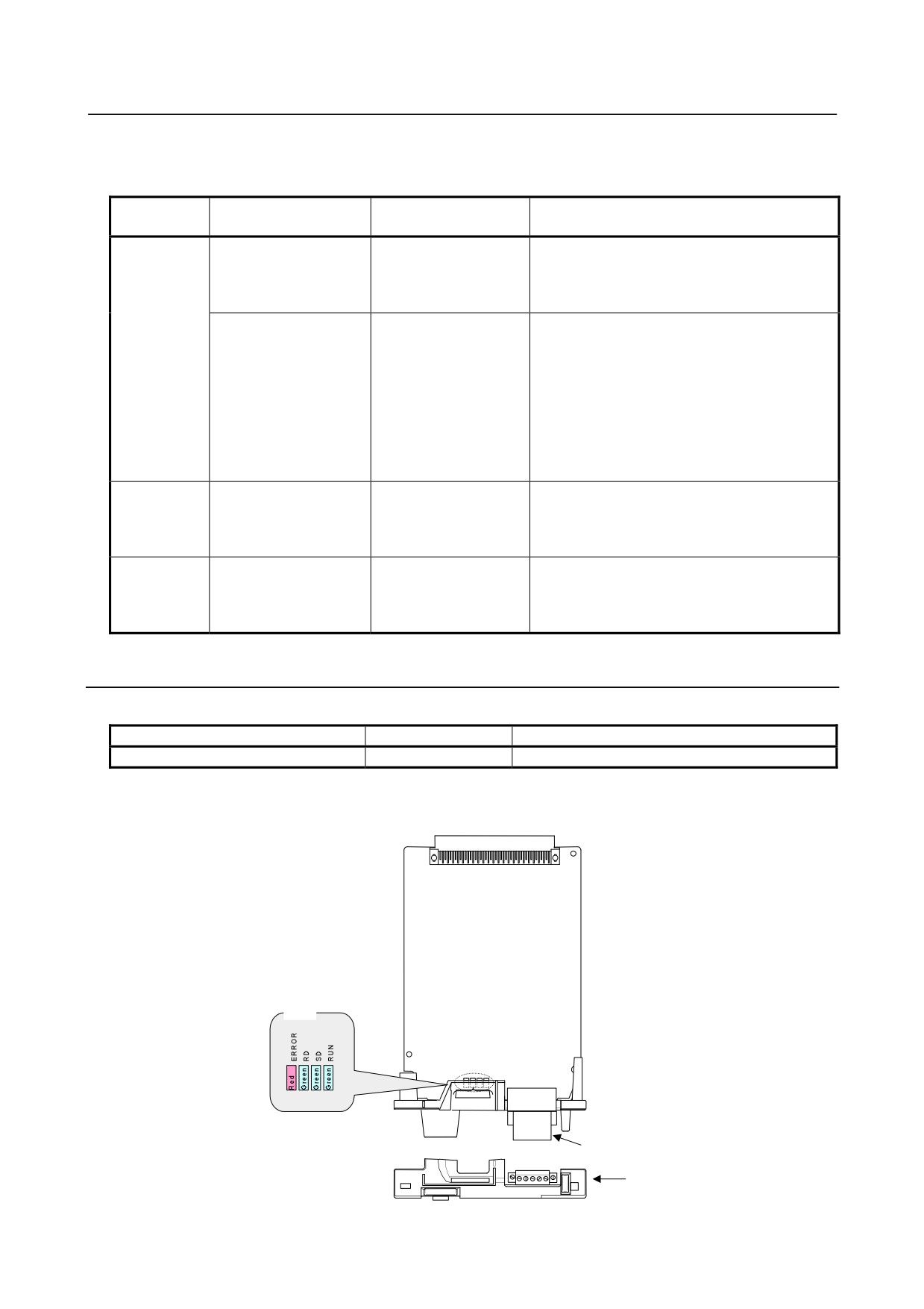
LED display of MS and NS (during occurrence of an unrecoverable failure)
In the "during occurrence of an unrecoverable failure" status, once an error occurred, recovery is not
performed unless this slave station is powered off and back on again.
LED
LED display
Status
Error and action
3 2 1 0
MS ◇ green
■□□□
Duplicate MAC IDs
Check the following and then turn the slave
MS ◇ red
↑↓
power off and back on again.
NS □ green
□□■□
→ MAC IDs are not duplicate by check the MAC
NS ■ red
(Repetition)
IDs of all nodes.
■□□□
Busoff detection
Check the following and then turn the slave
↑↓
power off and back on again.
□□■■
→ The communication rates of all nodes are set
(Repetition)
to the same value.
→ The cable length is appropriate.
→ The cable is not loose or broken.
→ A terminal is placed on only both ends of the
main line.
→ There is not much noise.
MS □ green
■□□□
Board failure
The DeviceNet slave board failed.
MS ■ red
↑↓
Replace the DeviceNet slave board.
NS ◇ green
□???
NS ◇ red
(Repetition)
MS ◇ green
□□□□
An unrecoverable failure
Contact FANUC.
MS ◇ red
↑↓
occurred on the CNC
NS ◇ green
■■■■
side.
NS ◇ red
(Repetition)
2.6.6
CC-Link Board
Specification
Name
Specification
Remark
CC-Link remote device station board
A20B-8101-0551
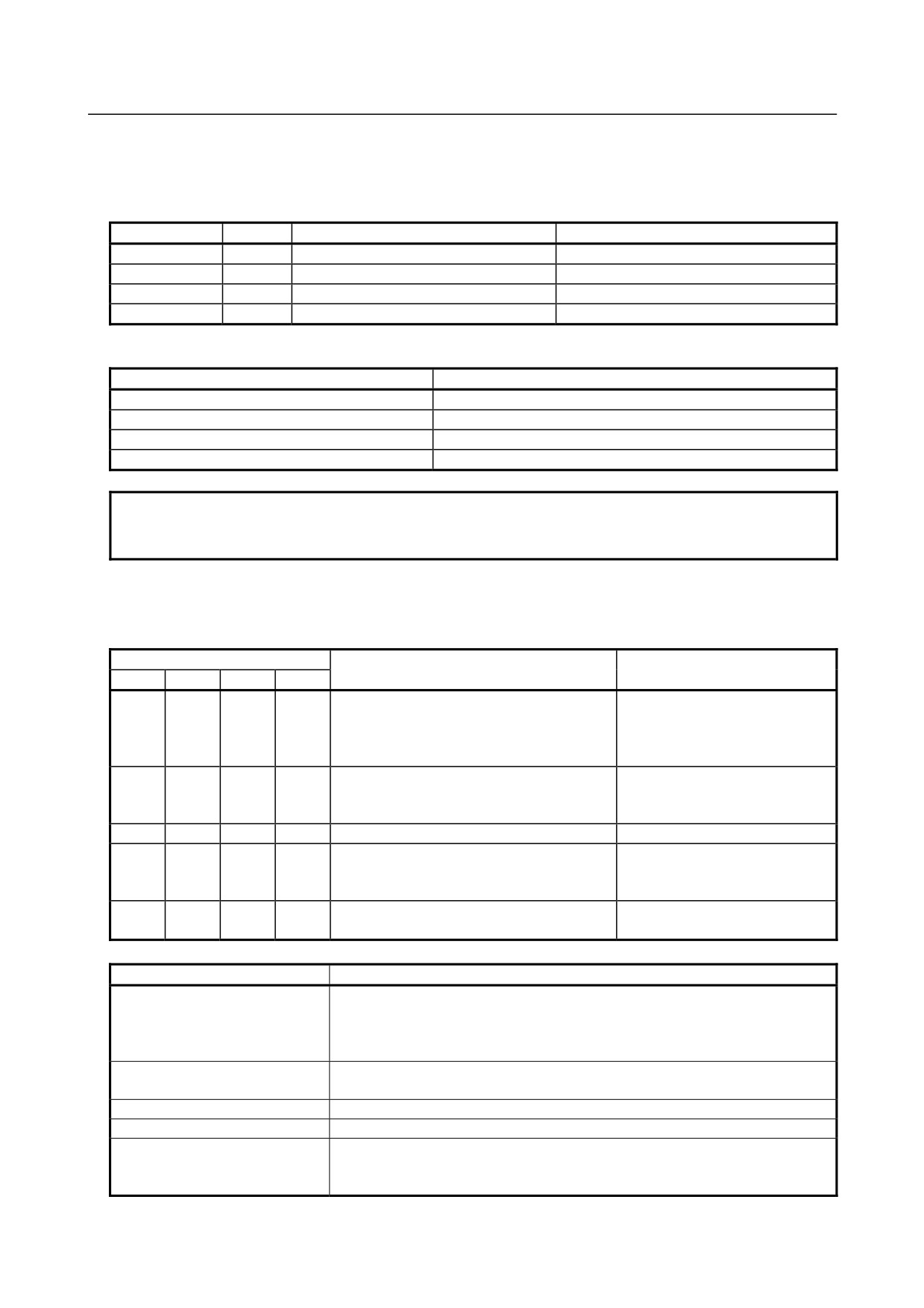
Connector and LED mounting location
CC-Link remote device station board
LED
Outside line
connector
Face plate
- 239 -
2.CONTROL UNIT HARDWARE
B-64485EN/01
LED display and their meanings
-
CCC-Link remote device station board
This board provides three green LEDs and one red LED for status indication.
Name
Color
On
Off
RUN
Green
Online
Offline
SD
Green
Sending data.
Not sending data.
RD
Green
Channel carrier detected.
Channel carrier error.
ERROR
Red
CRC error detected.
Communicating normally.
In the usual, normal communication state, the on/off states of the LEDs are as follows:
Name
On/off state
RUN
On
SD
Blinking
RD
On
ERROR
Off
NOTE
If the number of units on the network is small, SD blinks at high speed, and it
may appear on not insteading of blinking to the human eye.
LED indicators in the event of an error
In any of the following LED states, check the settings as listed in the table below.
□: Off
■: On
☆: Blinking
◇: Don’t care
LED
Meaning of the state
Check item
RUN
SD
RD
ERR
Cable connection
Terminating resistors
◇
◇
◇
☆
•
A CRC error occurred.
Measures against noise
Baud rate
•
Data destined to the local station
Settings of the master station
■
□
■
□
cannot be received from the master
station.
□
☆
■
□
•
The master station is not link-started.
Settings of the master station
Cable connection
□
□
■
□
•
Data cannot be received.
Measures against noise
Settings of the master station
•
The cable is disconnected.
Cable connection
□
□
□
□
•
The master station is not turned on.
Settings of the master station
Check item
What to check
•
The cable is not connected.
•
The cable and the connector are connected together correctly.
Cable connection
•
The cable is not bend forcibly.
•
The inter-slave station distance is correct.
•
Terminating resistors are connected to both ends of the cable.
Terminating resistors
•
The terminating resistors match the cable type.
Measures against noise
•
Each unit is grounded.
Baud rate
•
The same baud rate is set for the master and slave stations.
•
The master station is turned on.
Settings of the master station
•
The master station is operating normally.
•
The settings of the master station are made correctly.
- 240 -
B-64485EN/01
2.CONTROL UNIT HARDWARE
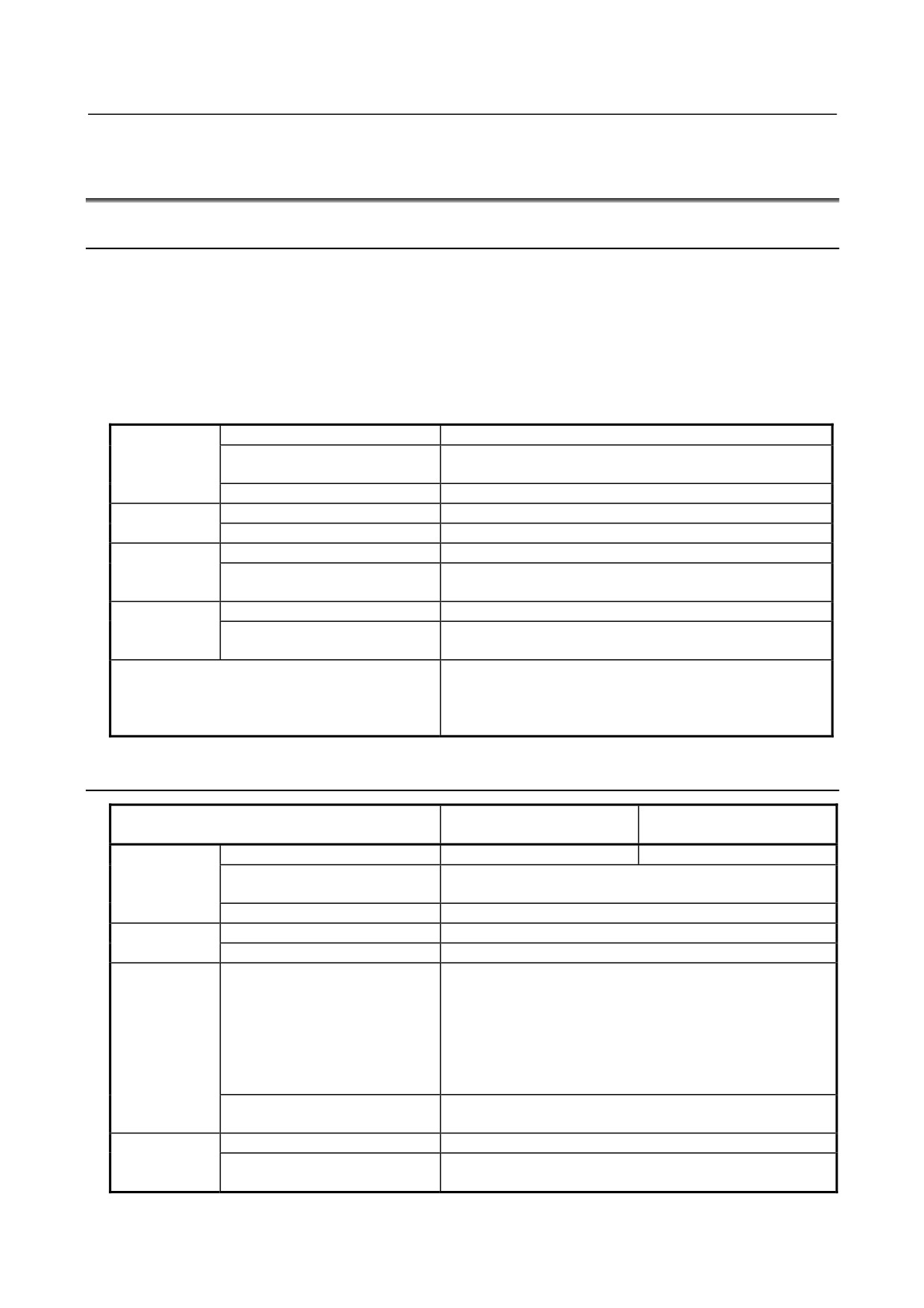
2.7
ENVIRONMENTAL REQUIREMENTS OUTSIDE THE
CABINET
2.7.1
Environmental Conditions outside the Cabinet
The control unit and the peripheral units have been designed on the assumption that they are housed in
closed cabinets. In this manual "cabinet" refers to the following:
• Cabinet manufactured by the machine tool builder for housing the control unit or peripheral units;
• Operation pendant, manufactured by the machine tool builder, for housing the display unit, MDI unit,
or operator's panel.
• Equivalent to the above.
The following table lists the environmental conditions required in installing these cabinets.
Operating
0°C to 45°C
Ambient
Nonoperating (including storage
temperature of
-20°C to 60°C
and transportation)
the cabinet
Temperature change
0.3°C/minute or less
Normal
75%RH or less, no condensation
Humidity
Short period (less than 1 month)
95%RH or less, no condensation
Operating
0.5G or less
Vibration
Nonoperating (including storage
1.0G or less
and transportation)
Operating
Up to 1000 m (see Note 1 in the Subsec. 2.7.2.)
Meters above
Nonoperating (including storage
sea level
Up to 12000 m
and transportation)
Normal machine shop environment
(The environment must be considered if the cabinets are in a
Environment
location where the density of dust, coolant, organic solvent,
and/or corrosive gas is relatively high.)
2.7.2
Installation Conditions of the Control Unit
LCD-mounted type control
Stand-alone type control
Condition
unit and display unit
unit
Operating
0°C to 58°C
0°C to 55°C
Ambient
Nonoperating (including storage
-20°C to 60°C
temperature
and transportation)
Temperature change
0.3°C/minute or less
Normal
75%RH or less, no condensation
Humidity
Short period (less than 1 month)
95%RH or less, no condensation
0.5G or less
FANUC’s evaluation test was conducted under the following
conditions complying with IEC 60068-2-6.
Operating
10 to 58Hz: 0.075mm (amplitude)
Vibration
58 to 500Hz: 1G
Direction of vibration: Each of the X, Y, and Z directions
Number of sweep cycles: 10
Nonoperating (including storage
1.0G or less
and transportation)
Operating
Up to 1000m (Note 1)
Meters above
Nonoperating (including storage
sea level
Up to 12000m
and transportation)
- 241 -
2.CONTROL UNIT HARDWARE
B-64485EN/01
LCD-mounted type control
Stand-alone type control
Condition
unit and display unit
unit
Coolant, lubricant, or cutting chips shall not be sprinkled
Environment
directly over the CNC or servo unit. No corrosive gas shall be
allowed.
NOTE
1 If the control unit is installed 1000 m or higher above sea level, the allowable
upper ambient temperature of the control unit in the cabinet is changed as
follows. Assume that the allowable upper ambient temperature of the control unit
in the cabinet installed 1000 m or higher above sea level decreases by 1.0°C for
every 100 m rise in altitude.
Example)
When a control unit whose required operating ambient temperature range is
0°C to 55°C is installed 1750 m above sea level:
55°C-(1750m-1000m)/100m × 1.0°C = 47.5°C
Therefore, the allowable ambient temperature range is from 0°C to 47.5°C.
2 When using a unit having additional installation conditions, be sure to meet also
these conditions.
2.8
CAUTIONS RELATED TO GROUNDING AND NOISE
The cabinet and pendant box generally have measures against electrical shocks and noise, such as
connecting grounding wires and separating cables on routing, in them. If you removed grounding wires
from the cabinet or pendant box, for example, in replacing a control or peripheral unit in the cabinet or
pendant box or if you temporarily changed the way other cables are laid or bound, basically restore their
original state of connection after maintenance work. Otherwise, it is likely that an electrical shock or
noise may result and the unit may malfunction.
This section describes the concept of cable separation, a noise suppresser as a measure against noise,
cable clamping and shield processing, and a lightning surge absorber.
2.8.1
Separating Cables
The cables used for the CNC machine tool are classified as listed in the following table. The cables in
each group must have been subjected to treatment stated in the Action column.
Table 2.8.1 Cable grouping
Group
Signal line
Action
A
Primary AC power line
Bind the cables in group A separately (Note 1) from
Secondary AC power line
groups B and C, or cover group A with an
AC/DC power lines (containing the power lines
electromagnetic shield (Note 2).
for the servo and spindle motors)
See Subsection 2.8.2 and connect spark killers or
AC/DC solenoid
diodes with the solenoid and relay.
AC/DC relay
B
DC solenoid (24 VDC)
Connect diodes with the DC solenoid and relay.
DC relay (24 VDC)
Bind the cables in group B separately from group
DI/DO cable between the I/O unit and power
A, or cover group B with an electromagnetic
magnetics cabinet
shield.
DI/DO cable between the I/O unit and machine
Separate group B as far from group C as
possible.
24 VDC input power cables connected to the
It is desirable to apply shield processing
control unit and its peripherals
described in Subsection 2.8.3.
- 242 -
B-64485EN/01
2.CONTROL UNIT HARDWARE
Group
Signal line
Action
C
I/O Link i or I/O Link cable
Bind the cables in group C separately from group
Cable for the position coder
A, or cover group C with an electromagnetic
Cable for the manual pulse generator
shield.
Separate group C as far from group B as
Cable for the MDI (Note 3)
possible.
RS-232C interface cable
Be sure to perform shield processing as
Cable for the battery
described in Subsection 2.8.3.
Cable for the Ethernet
Other cables for which shield processing is
specified
NOTE
1
Binding the cables in one group separately from another means that the groups
are placed 10 cm or more apart from one another.
2
Covering a group with an electromagnetic shield means that shielding is
provided between groups with grounded steel plates.
3
The shield is not required when the cable for the MDI is no more than 50 cm in
length.
CAUTION
Select a cable with a proper length. If the cable is too long, the noise immunity
may be reduced or noise may be caused on other cables. In addition, when the
excess length is coiled, the inductance is increased and a high voltage is
induced during turning on or off of signals. This may cause a failure or a
malfunction due to noise.
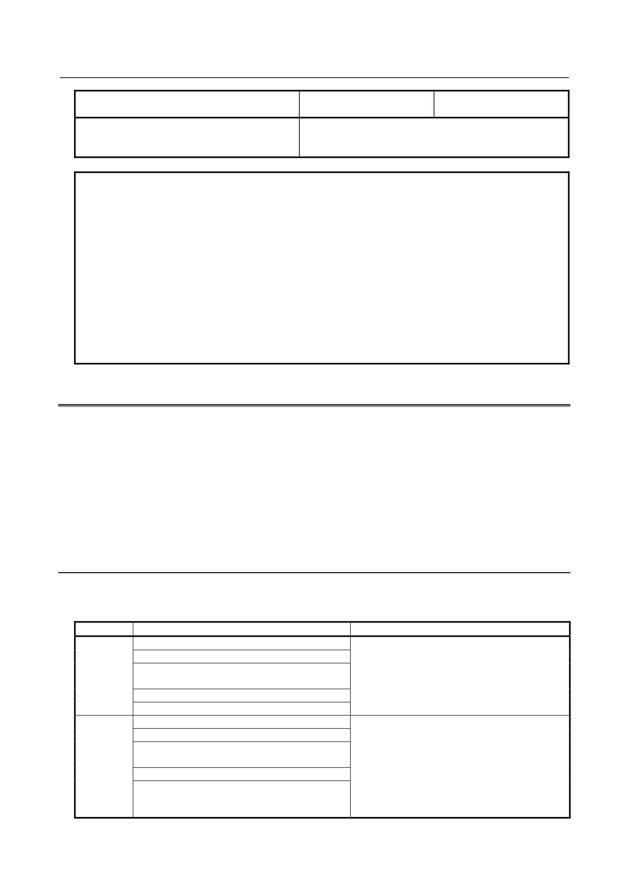
Cabinet
Pendant box
24VDC
Spindle
Servo
I/O
Control
Unit
amplifier
amplifier
unit
receiving
power
Unit
AC
supply
voltage
Duct
Shielding
To motor
plate
and the like
Cable of group A
Cable of group B, C
Section of duct
Group A
Group B, C
Shielding plate
Fig. 2.8.1 Cable layout example
- 243 -
2.CONTROL UNIT HARDWARE
B-64485EN/01
2.8.2
Noise Suppressor
A noise suppressor must be installed as a measure against noise that may occur in actuators such as
solenoids and relays used in the power magnetics cabinet.
Because an actuator, which converts electrical energy to mechanical action, is an inductive load, it
resonates with the parasitic capacitance in a circuit containing it, when it works on and off, thus
generating intermittent arcs accompanied by abrupt voltage rises and falls at its contacts, hence
electromagnetic waves interfering with electronics circuits. As a remediation measure, treat the inductive
load as described below.
1)
While referencing the processing for cable groups A and B described in Subsection
2.8.1,
“Separating Signal Lines”, apply a CR snubber circuit and a diode, respectively, to an inductive load
in an AC circuit and that in a DC circuit.
2)
When selecting a CR snubber or diode, observe the following cautions.
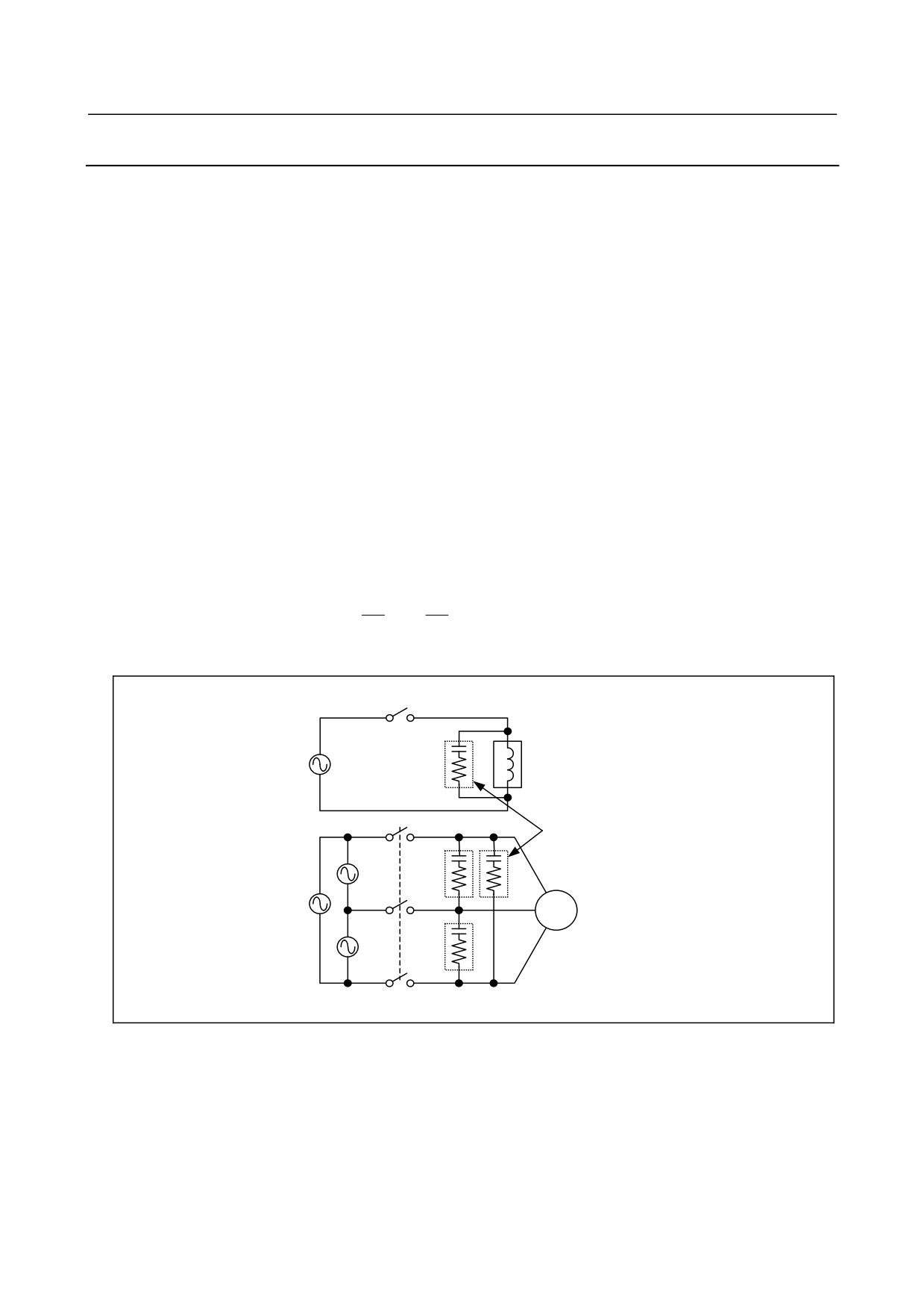
Cautions for selecting and using a CR snubber
• Use a CR snubber in an AC circuit.
A varistor, voltage clamping element, can limit the peak of an oscillating voltage waveform but
cannot relax an abrupt voltage transition . For this reason, we recommend using a CR snubber rather
than the varistor.
• Determine the rating of the resistor and capacitor in the CR snubber according to the steady-state
current I (A) and DC resistance RL (Ω) of the inductive load as follows:
1)
CR snubber resistance: R ≅ RL
(Ω)
2
2
I
I
2)
CR snubber capacitance:
≤
C
≤
(μF)
10
20
• Place the CR snubber close to the inductive load to minimize its wiring.
Inductive load (such as relay䋩
CR snubber
Motor
General-purpose induction motor
Fig. 2.8.2 (a) Example of applying a CR snubber
Cautions for selecting and using a diode
• A diode (freewheeling diode) can be used as a noise suppressor for a DC driver circuit.
• Determine the ratings of the diode according to the drive voltage and current for the inductive load
(such as a solenoid coil, relay, or motor) as follows:
1)
Voltage rating: Approximately twice the voltage applied to the inductive load
2)
Current rating: Approximately twice the steady-state current flowing through the inductive load
- 244 -
B-64485EN/01
2.CONTROL UNIT HARDWARE
• Place the diode close to the inductive load in order to minimize its wiring.
+
Inductive load (such as a relay䋩
Diode
Fig. 2.8.2 (b) Example of applying a diode
2.8.3
Cable Clamp and Shield Processing
Each cable leading into this control unit, servo amplifiers, or spindle amplifiers that requires shielding so
as to suppress external noise has been clamped (basically signal cables require shield clamps). So when
the cable replaced by a new one, confirm that the shield processing complies with following
requirements.
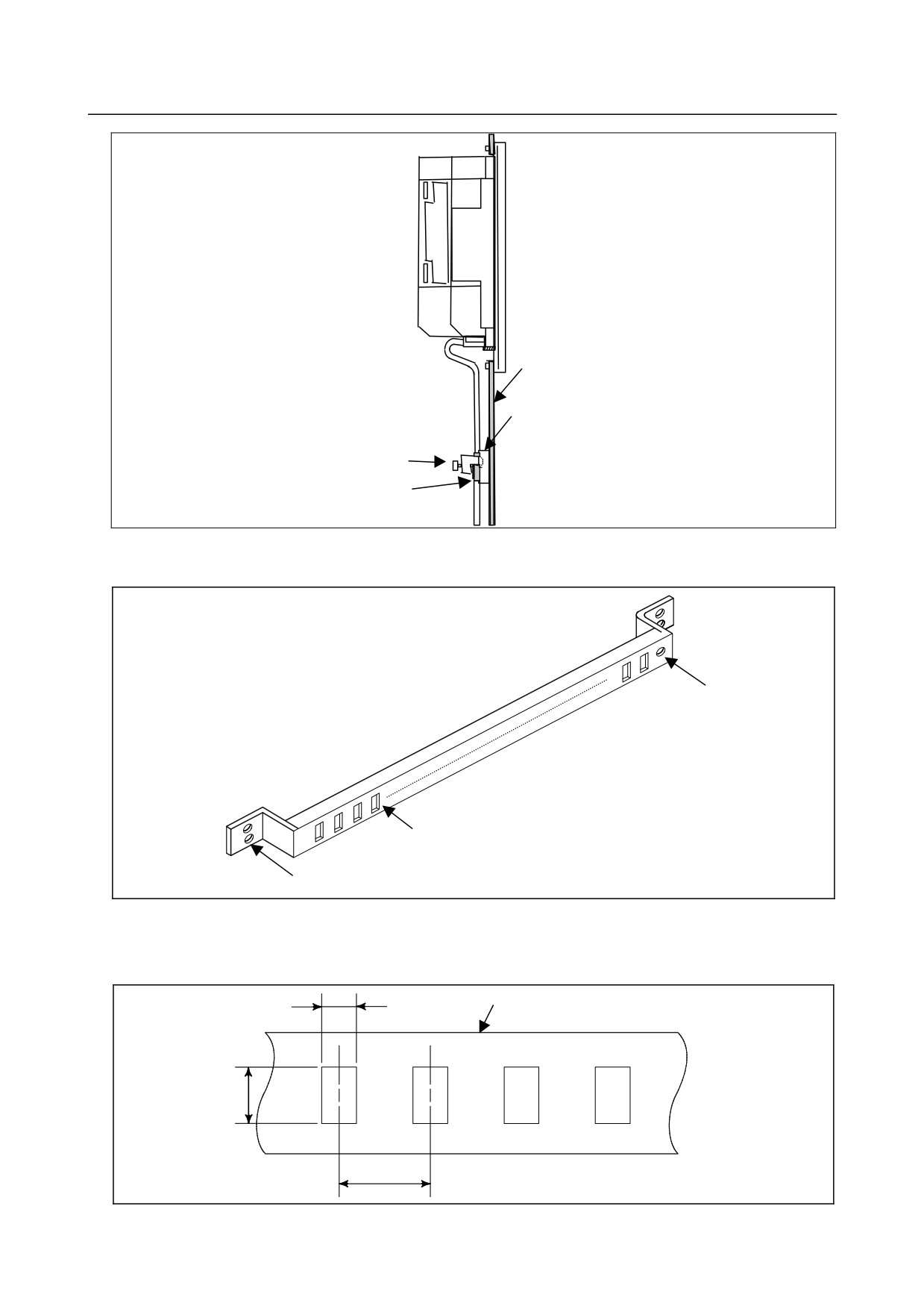
Partially peel the sheath off each of such cables and expose the shield, and press the exposed portion
against a ground bar with a clamp. Care should be taken so that the ground bar and shield have a surface
contact in a larger area.
The ground bar for the cable clamp must be installed as shown in Fig. 2.8.3 (a).
When the multipoint grounding scheme is used, care should be taken so that the ground bar for the shield
clamp and cabinet are connected at low impedance by, for example, preventing the cabinet side contact
surface from being coated.
When using an in-line connector or the like to split a cable, it is necessary to connect the shield of one
portion of the cable and that of the other portion and to keep the total impedance of the two cable portions
from becoming high. Even if the connector is placed at the inlet of the cabinet, it is also necessary to use
the shield for the intra-cabinet portion of the cable all the way to the other end of the cable.
Ground bar for shield clamp
Cable
Metal fittings
for clamp
Fig. 2.8.3 (a) Cable clamp (1)
NOTE
Bundle and clamp the shields of cables that lead into the control unit or amplifier
at a point, respectively, close to the unit or amplifier.
- 245 -
2.CONTROL UNIT HARDWARE
B-64485EN/01
Control unit
Cabinet
Ground bar for shield clamp
Metal fittings for clamp
Shield
Fig. 2.8.3 (b) Cable clamp (2)
Prepare a ground bar for cable clamping shown below.
Ground terminal
(grounded)
Hole for securing metal
fitting clamp
Mount screw hole
Fig. 2.8.3 (c) Ground bar for shield clamp (outline drawing)
The ground bar for cable clamping must be made of a steel plate at least 2 mm thick and plated with
nickel.
Ground bar for shield clamp
8
12
20
(Unit: mm)
Fig. 2.8.3 (d) Ground bar for shield clamp (hole arrangement and dimension drawing)
- 246 -
B-64485EN/01
2.CONTROL UNIT HARDWARE
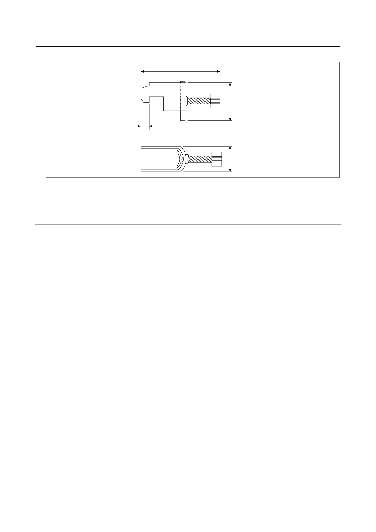
Max. 55
Reference)
28
6
17
(Unit: mm)
Fig. 2.8.3 (e) Clamping metal fixture (outline drawing)
Ordering specification for metal fittings for clamp
A02B-0303-K001 (8 pieces)
2.8.4
Lightning Surge Absorber
A lightning surge absorber installed between input power lines and between input power lines and the
ground might be effective to protect units from lightning voltage surges. However, installing a surge
absorber does not always ensure protection from lightning surges. How to install the lightning surge
absorber is explained below.
Installation procedure
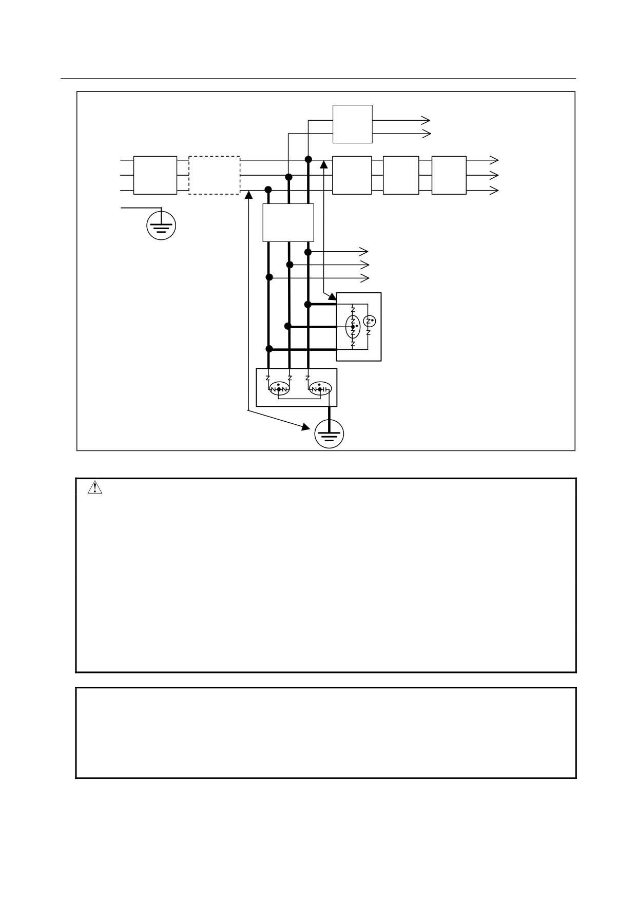
The surge-absorbing elements used for measures against surges due to lightening must be installed in the
input power unit as shown in the figure below. The figure below shows an example in which an insulating
transformer, shown by dotted lines, is not installed. If an insulating transformer is installed,
surge-absorbing element 2 (between line and ground) is not required.
- 247 -
2.CONTROL UNIT HARDWARE
B-64485EN/01
To control power input for control unit
Circuit
24 VDC power and control power
breaker
supply input of Power Supply for
(MCCB)
servo amplifier
R
To main circuit
AC
Circuit
Insulating
Circuit
Magnetic
AC
input
contactor
power input of
S
breaker
transformer
breaker
reactor
Power Supply for
(MCCB)
(MCCB)
T
servo amplifier
PE
Circuit
breaker
a
(5A,MCCB)
To other electric parts on the machine
b
Surge-absorbing element 1
(between lines)
Surge-absorbing element 2
(between line and ground)
Fig. 2.8.4 Example of installing lightning surge absorbers on 200 VAC lines
CAUTION
1 For a better surge absorbing effect, the wiring shown by heavy line must be as
short as possible.
Wire size : Cross-sectional area at least 2 mm2 large
Wire length: The sum of the length (a) of the wire for the connection of
surge-absorbing element 1 and that (b) of surge-absorbing element
2 must be 2 m or less.
2 If conducting dielectric strength tests by applying overvoltages (1000 VAC and
1500 VAC) to the power line, remove surge-absorbing element 2. Otherwise, the
overvoltages would activate the element.
3 The circuit breaker (5A) is a short circuit protection of lines if the surge-absorbing
elements result in short circuit breakdown due to the absorption of an excessive
amount of energy.
NOTE
The circuit breaker (5A) can be used also for other electric parts on the machine
because no current flows through surge-absorbing elements 1 and 2 in the
normal state. The “other electric parts on the machine” can be the control power
supply of Power Supply for servo unit and the power supply for the fan motor for
a spindle motor.
- 248 -
B-64485EN/01
3.REPLACING CONTROL UNIT MAINTENANCE PARTS
3 REPLACING CONTROL UNIT
MAINTENANCE PARTS
3.1
CAUTIONS FOR REPLACEMENT
WARNING
1
Only those personnel who have received approved safety and maintenance
training may perform this replacement work. When opening the cabinet and
replacing the board, be careful not to touch the high-voltage circuits (marked
with
and fitted with an insulating cover). If you touch any uncovered
high-voltage circuit, you will get an electric shock.
2
Before exchanging, be sure to shut off externally supplied power. Otherwise,
electrical shocks, breakdown, and blowout may occur.
If a control unit is turned off but other units are not, it is likely that power may be
supplied to servo units, resulting in the units being damaged and workers getting
an electrical shock when the units are exchanged.
3
In order to prevent damage that may be caused by static electricity, wear a
grounding wrist strap or take a similar protective measure before starting to
touch a printed-circuit board or unit or attach a cable.
Static electricity from human bodies can damage electrical circuits.
4
Voltage lingers in servo and spindle amplifiers for a while even after power has
been turned off, resulting in workers possibly getting an electrical shock when
the workers touch them. Before starting to exchange these amplifiers, wait for 20
minutes after power has been turned off.
5
When replacing a unit, ensure that the new unit has the same parameters and
settings as the old one. (For details, refer to the manual for the machine.)
Otherwise, unpredictable machine movement could damage the workpiece or
the machine itself or cause injury.
6
If you notice an apparent hardware fault, such as abnormal noise, abnormal
odor, smoke, ignition, or abnormal heat, in the hardware while power is being
supplied to it, shut it off at once. These faults can cause fire, breakdown,
blowout, and malfunction.
7
The radiating fins of control units, servo amplifiers, spindle amplifiers, and other
devices can remain very hot for a while after power has been turned off, making
you get burned if you touch them. Before starting to work on them, wait and
make sure they are cool.
8
When exchanging heavy stuff, you should do so together with two or more
people.
If the replacement is attempted by only one person, the old or new unit could slip
and fall, possibly causing injury.
9
Be careful not to damage cables. Otherwise, electrical shocks can occur.
10 When working, wear suitable clothes with safety taken into account. Otherwise,
injury and electrical shocks can occur.
11 Do not work with your hands wet. Otherwise, electrical shocks and damage to
electrical circuits can occur.
- 249 -
3.REPLACING CONTROL UNIT MAINTENANCE PARTS
B-64485EN/01
NOTE
The LCD (liquid-crystal display) has been fabricated using an extreme precision
technology. However, some of their pixels may fail to light or stay constantly
lighting because of their characteristics. Please be forewarned that these
phenomena are not faults.
3.1.1
Optional Information File
This control unit supports the “FANUC Remote Option System”. Optional parameters are held as an
optional information file (named “OPRM INF”) in FROM
Cautions for optional information file restoration
1)
When making a backup copy of SRAM data and user files, make a backup copy also of an optional
information file (named “OPRM INF”) in FROM. The optional information file is needed when the
optional information must be restored, for example, because of it having been damaged.
2)
Once the optional information file is restored, alarm PS5523 “OPTION AUTHENTICATION WAIT
STATE” is issued at power-on, indicating that the optional parameters must be authenticated by the
FANUC service department within the period of validity (within 30 days since the occurrence of the
alarm). Alarm PS5523 can be canceled by a reset within the period of validity. Contact the FANUC
service department for information about the authentication procedure.
3.1.2
Attaching and Detaching Units
LCD-mounted type control units, display units, MDI units, and main panel machine operator's panels, can
be categorized into two types in terms of the way they are mounted. One of the types is fixed using M4
nuts through the rear surface of the unit, and the other type is fixed using M3 screws through the front
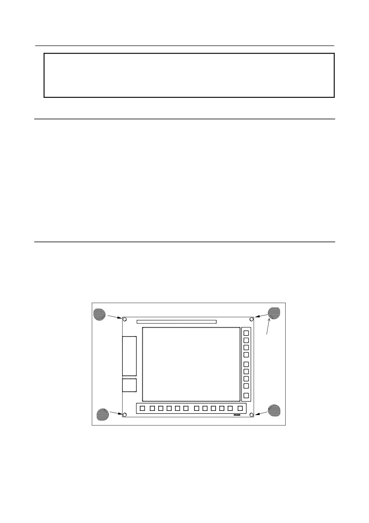
surface of the unit. The front surface-mount type units use screw caps for covering the screw holes in its
corners.
When attaching the M3-fixed type unit mentioned above to, or detaching it from, a cabinet, follow the
procedure below while paying attention to the screw caps.
Slot
Detaching
1.
Pull out the screw cap from the screw hole in each corner by inserting a precision screwdriver (flat
blade) into the slot in the screw cap head.
2.
Remove the screw which appeared each screw cap was detached to detach the unit.
- 250 -
B-64485EN/01
3.REPLACING CONTROL UNIT MAINTENANCE PARTS
Attaching
1.
Fasten the unit by inserting a screw into the screw hole in each corner. Tighten the screws with an
appropriate torque.
2.
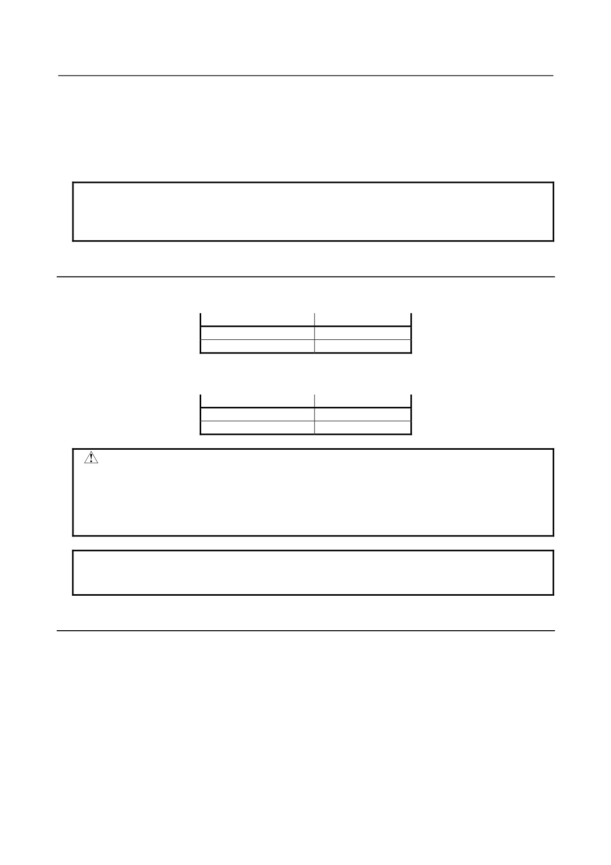
Cover each screw hole with a screw cap while making sure that all the screw caps are oriented in
such a way that their slots face in the respective directions shown in the figure. Push in each screw
cap until they become flush with the surface of the unit.
NOTE
The ordering information for the screw caps is as follows:
A02B-0319-K190: A set of 100 screw caps
A02B-0319-K191: A set of 5 screw caps
3.1.3
Tightening Torque for Fastening Units and Ground Terminals
The following table lists the tightening torque for screws and nuts used to fasten the units (except those
having molded mounting parts) explained herein and ground terminals in the units.
Screw and nut diameter
Tightening torque
M3
0.8 to 1.0 N⋅m
M4
1.6 to 2.0 N⋅m
The following table lists the tightening torque for screws and nuts used to fasten those units having
molded mounting parts, such as stand-alone control units and separate detector interface units.
Screw and nut diameter
Tightening torque
M4
1.1 to 1.5 N⋅m
M5
2.4 to 2.8 N⋅m
CAUTION
Be sure to observe the rules listed above when tightening screws. If screws are
tightened too weakly or too strongly, it is likely that the unit may drop, break, or
malfunction.
For units having a touch panel in particular, be sure to observe the above rules.
Failing to observe them can cause the touch panel to malfunction.
NOTE
For units having different installation conditions specified herein, observe them
first.
3.1.4
Packing
Each FANUC-supplied unit, such as a display or operator’s panel, has been designed on the assumption
that they will be mounted using packing and with the specified screw tightening torque. Failing to mount
them as specified can lead to unit damage and/or malfunction. Be sure to use packing and observe the
specified screw tightening torque. When replacing the packing, do so neatly so that no coolant will get in
the unit after replacement. Observe the following precaution when attaching the packing.
When making screw holes in packing, be careful not to cut to the edge of the packing. Any extra cut can
let coolant get in the cabinet through the screw hole, causing trouble.
- 251 -