FANUC Series 30i-MODEL B, 31i-MODEL B, 32i-MODEL B. MAINTENANCE MANUAL - page 10
3.REPLACING CONTROL UNIT MAINTENANCE PARTS
B-64485EN/01
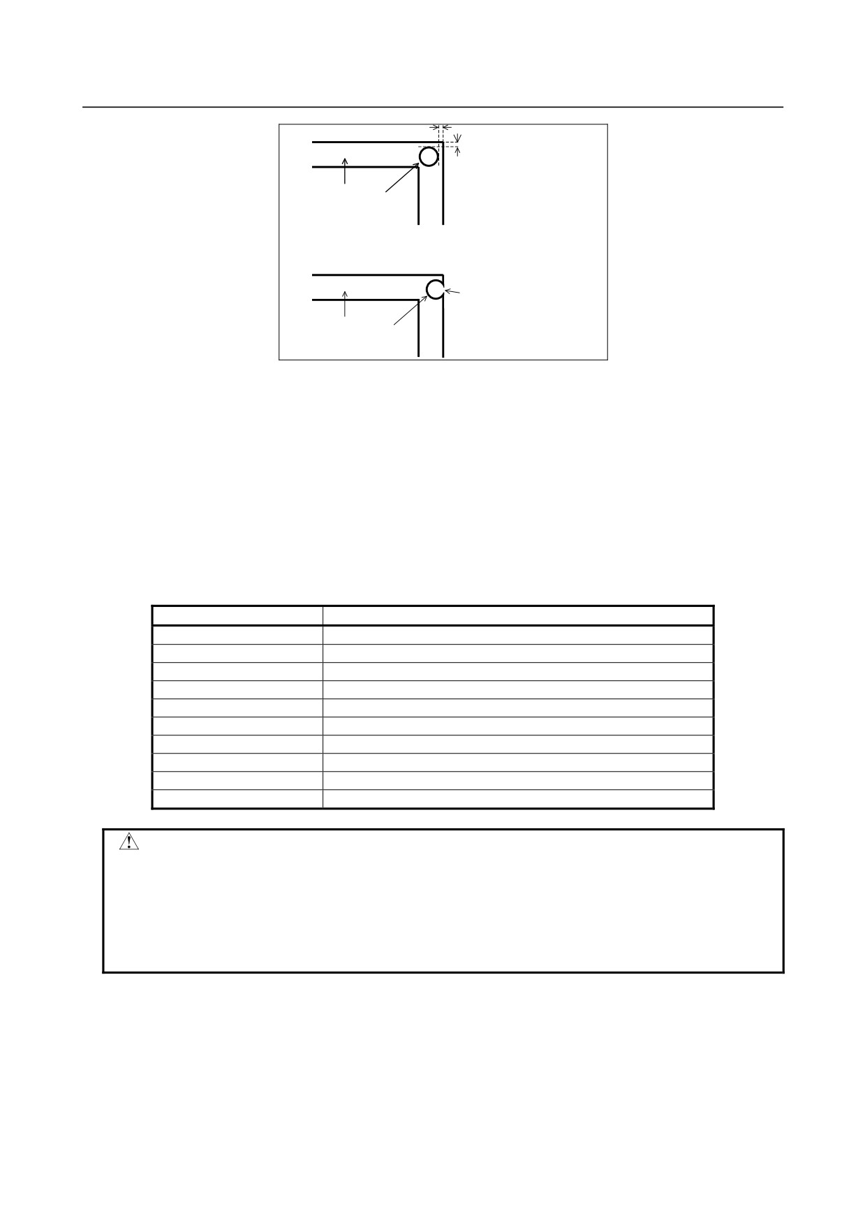
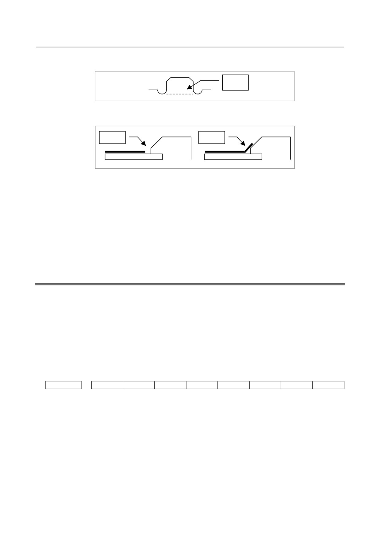
Packing
Screw hole
*) When making screw holes in packing, be careful not to cut to the edge of the packing.
Any extra cut can let coolant
get in the cabinet through the
screw hole.
Packing
Screw hole
Packing for LCD units, MDI units, and standard machine operator’s panels
Observe the following rough standards for the thickness and hardness of packing used with LCD units
(included LCD-mounted control units or display units), MDI units, and main panel of standard machine
operator’s panel.
Thickness
:
1.4mm(including double-stick tape)
Hardness
:
8(Asker C)
The following models of packing can be purchased from FANUC. These models are electrically
conductive. When they are used to mount a unit on a cabinet or pendant box, they leave no electrical gap
between the unit and cabinet or pendant box, being effective in electromagnetic wave shielding and EMC
measures.
Ordering information
Use
A02B-0323-K302
For 8.4” LCD unit, for standard MDI unit (ONG 8.4” LCD unit)
A02B-0323-K301
For 10.4” LCD unit, for standard MDI unit (ONG vertical type)
A02B-0323-K300
For 12.1” LCD unit
A02B-0323-K304
For 15” LCD unit
A02B-0323-K306
For display unit for automotive manufacture
A02B-0323-K310
For standard MDI unit (ONG vertical type)
A02B-0323-K313
For small MDI unit (ONG 8.4” LCD unit)
A02B-0323-K314
For standard MDI unit (QWERTY)
A02B-0323-K315
For standard MDI unit (QWERTY type B)
A02B-0323-K320
For main panel of standard machine operator’s panel
CAUTION
1 We have evaluated the above models of packing for many different coolants.
However, we do not necessarily guarantee that they are resistant to all coolants.
They are not resistant to, for example, coolants containing sulfur or chlorine at a
high activation level and water-soluble coolants at a high alkali level.
2 When attaching these models of packing, observe the cautions provided
together with them.
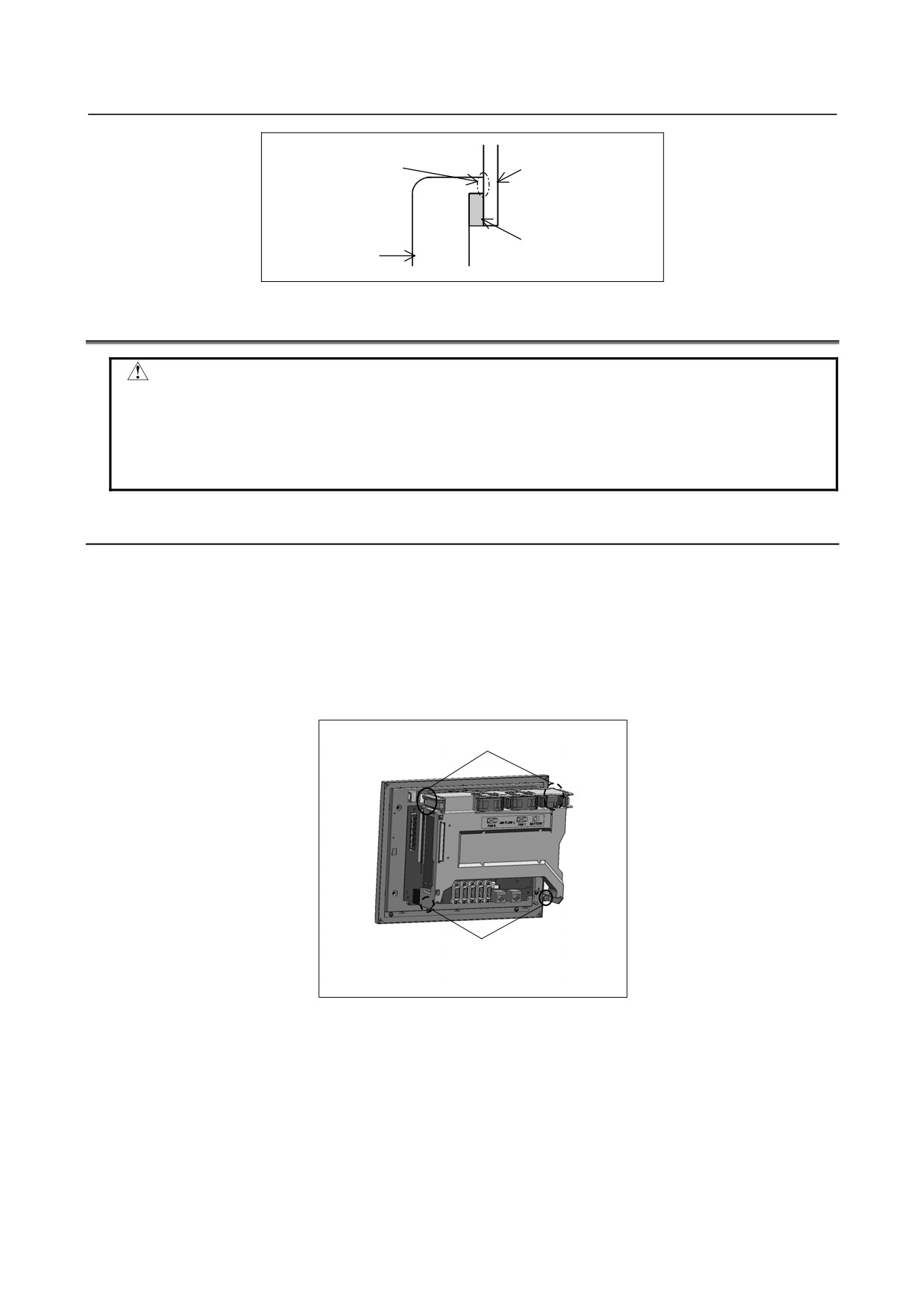
When using packing to install a LCD unit, MDI unit, or standard machine operator’s panel in a cabinet or
pendant box, be careful not to pinch the packing between the mounting surface of the cabinet or pendant box
and the brim of the unit being installed.
- 252 -
B-64485EN/01
3.REPLACING CONTROL UNIT MAINTENANCE PARTS
When attaching packing,
Cabinet, pendant box
be careful not to pinch it.
LCD unit, MDI unit,
standard machine operator’s
Packing
panel
3.2
REPLACING THE MAIN BOARD
CAUTION
Before starting to replace the main board, make a backup copy of the contents
(parameters, programs, etc.) of SRAM in the CNC. The SRAM contents may be
lost during replacement. See Chapter 5, “INPUT AND OUTPUT OF DATA”, and
Appendix C, “BOOT SYSTEM” for explanations about how to make backup
copies. Also see Subsection 3.1.1, “Optional Information File”.
3.2.1
LCD-mounted Type Control Unit
Replacement procedure
1)
Remove each cable from the control unit. Take out the control unit from the cabinet while
referencing Subsection 3.1.2, “Attaching and Detaching Units”.
2)
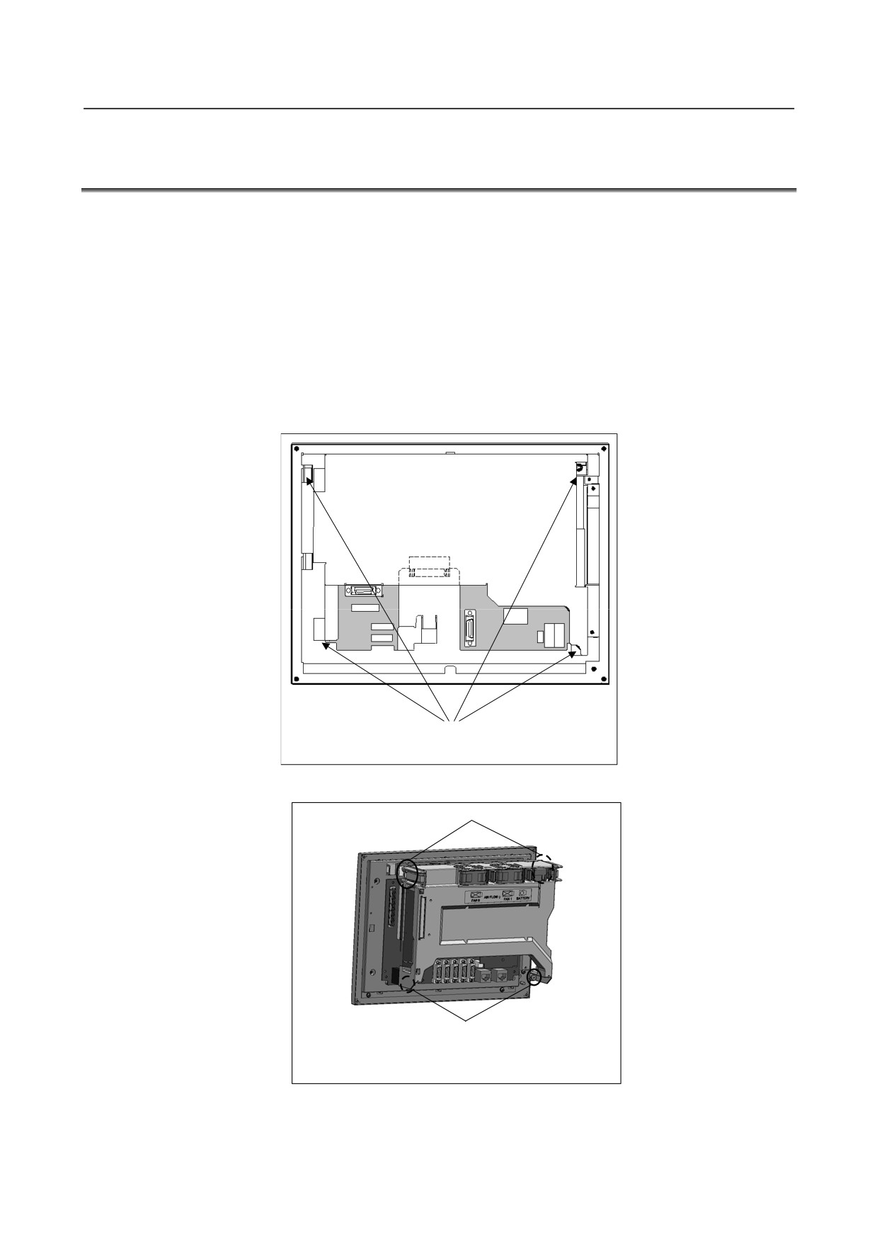
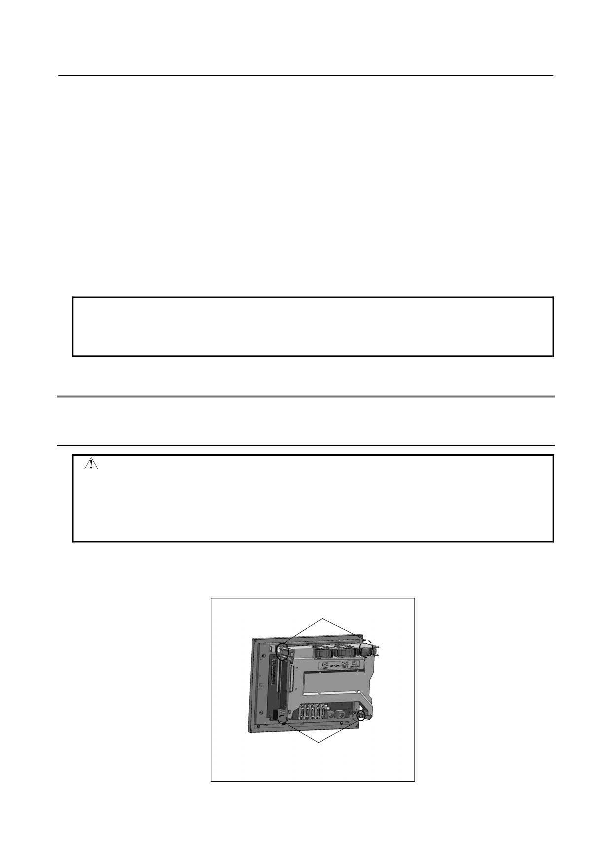
Detach the two screws in the lower section of the case unit from the main board. The structure is
such that the two screws will not come off the case unit.
3) Pull out the case unit while unlatching the claws from the metal bases on both sides in the upper
section of the case unit. The case unit comes out together with the back panel, fan motor, and lithium
battery.
Claws
Detach screws.
Note) The structure is such that the screws will not come off the case.
- 253 -
3.REPLACING CONTROL UNIT MAINTENANCE PARTS
B-64485EN/01
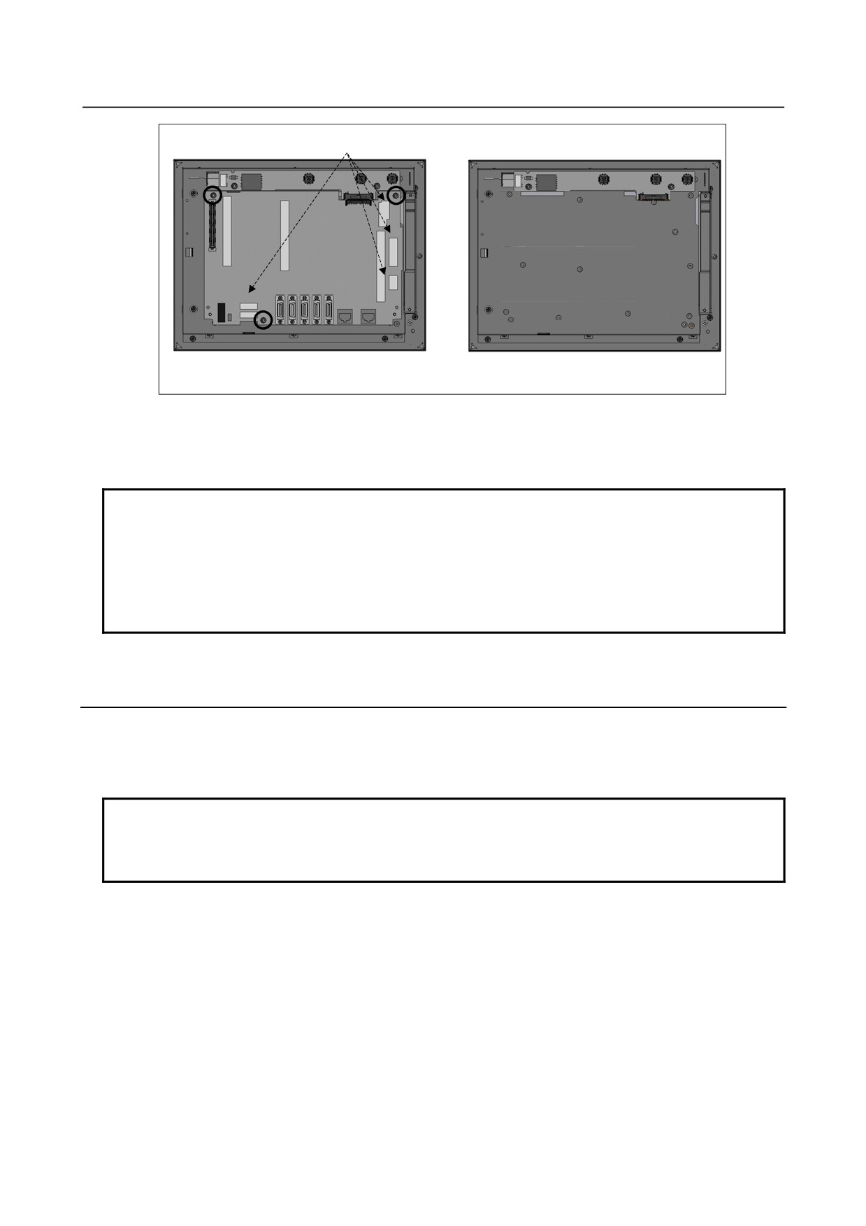
4)
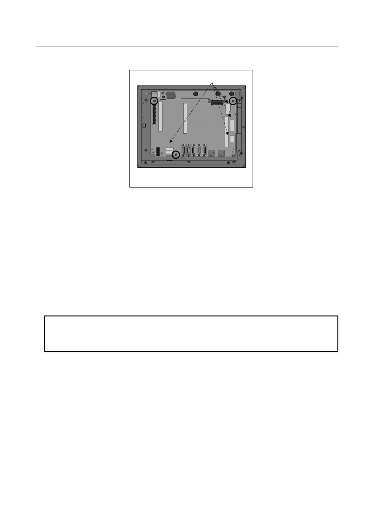
Remove the cable from each connector on the main board. Also remove the screws fastening the
main board.
Remove the cables (CK20A, CK21A, CA130, CA88A, and CA46A).
CA132
CA130
CA88A
CA46A
CK20A
CK21A
Remove the screws (3 places) fastening the main board.
Detaching the main board from the 10.4” LCD unit-mounted control unit
5)
Detach the main board by pulling it down because the main board and inverter board is connected
using the connector CA132 (for the inverter board).
6)
After moving the cards and modules from the detached main board to another (replacing) main
board, attach the replacing main board.
7)
Connect the main board to the inverter board and fasten it with screws. Re-attach each cable to the
main board while exercising care not to attach them incorrectly.
8) Place the case in such way that its screws and latches align with their positions, and push it in slowly.
When pushing it in, make sure that the back panel and main board engage with their respective
connectors securely and pay attention not to apply an excessive force. After making sure that the
case unit is latched securely, tighten the case unit screws. Also make sure that the fan motor and
battery are connected securely.
9)
While referencing Subsection 3.1.2, “Attaching and Detaching Units”, attach the control unit to the
cabinet. Re-attach the cables to the control unit. Be careful not to attach them incorrectly.
NOTE
Once the main board on a control unit with a touch panel is replaced, the touch
panel needs to be calibrated. See Section 3.14 for explanations about how to
adjust the touch panel.
- 254 -
B-64485EN/01
3.REPLACING CONTROL UNIT MAINTENANCE PARTS
3.2.2
Stand-alone Type Control Unit
Replacement procedure
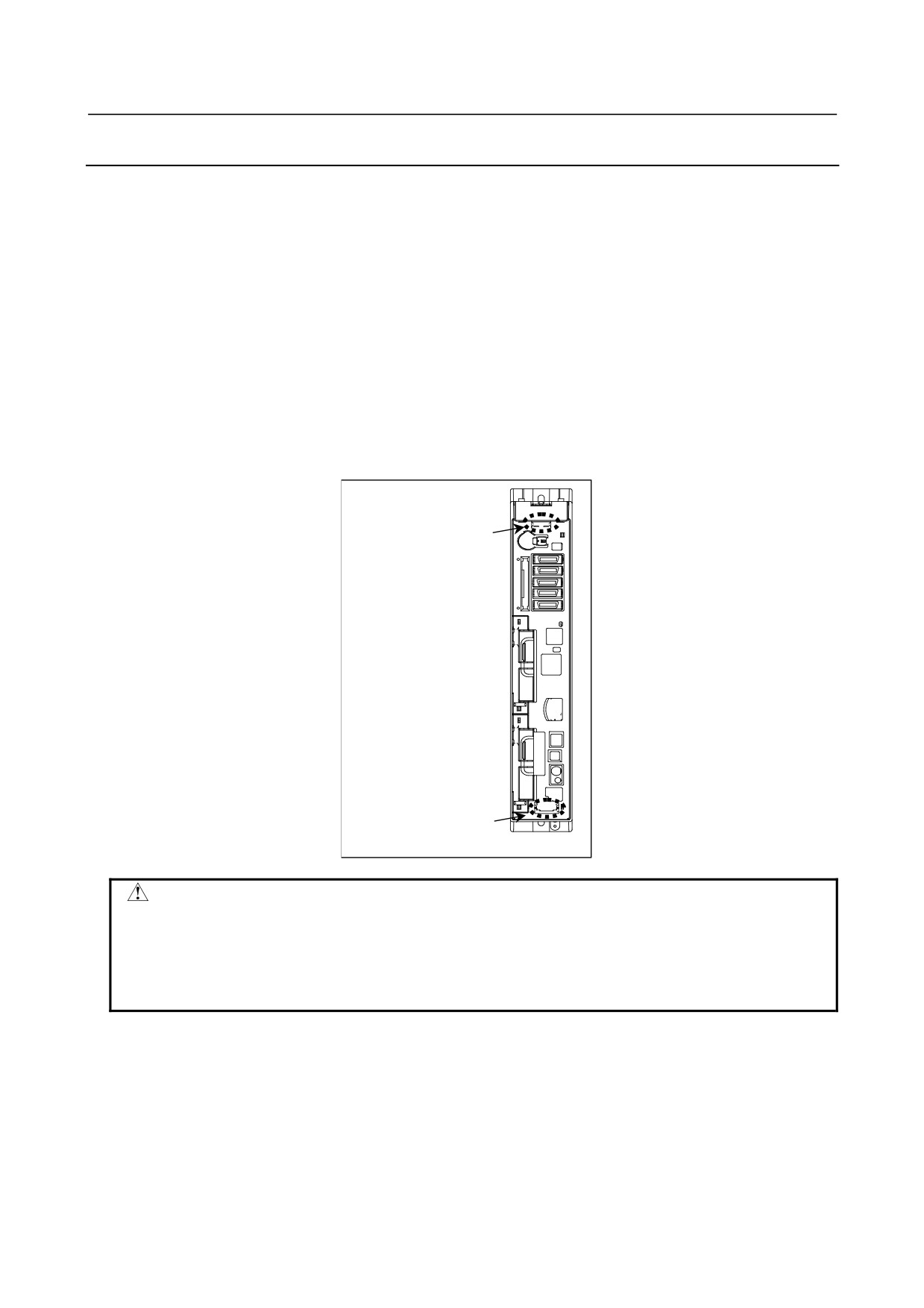
1)
Remove each cable from the control unit. (The lithium battery need not be removed because it is on
the face plate of the main board.)
2)
Remove the fan unit.(Caution)
3)
Hold handles A and B.
4)
Pull out the printed circuit board while pushing down the hook of handle A and pushing up the hook
of handle B.
5)
After moving the cards and modules from the detached main board to another (replacing) main
board, attach the replacing main board.
6)
While holding handles A and B, push the main board into the control unit slowly and engage it with
the back panel connector. Make sure that the hooks of handles A and B have latched on the case.
7)
While referencing Subsection 3.11.2, attach the fan unit. Note that, unless the main board is engaged
with the back panel securely, the fan unit cannot be mounted.
8)
Re-attach the cables correctly.
A
The hook is on the upper side.
B
The hook is on the lower side.
CAUTION
The main board is so structured that it is fastened to the control unit with the fan
unit. For this reason, the main board cannot be detached if the fan unit is
mounted on the control unit. Before starting to detach or attach the main board,
be sure to remove the fan unit.
See Subsection 3.11.2 for explanations about how to remove the fan unit.
- 255 -
3.REPLACING CONTROL UNIT MAINTENANCE PARTS
B-64485EN/01
3.3
REPLACING THE DISPLAY CONTROL BOARD FOR THE
DISPLAY UNIT
Replacement procedure
1)
Detach each cable from the display unit. While referencing Subsection 3.1.2, “Attaching and
Detaching Units”, take out the display unit from the cabinet.
2)
[Display unit (with 10.4” LCD unit A)]
Remove the screws from the cover and detach the cover. If the display unit is a type having a touch
panel, remove the cable from the touch panel control board before detaching the cover.
[Other types of display units]
Remove the two screws from the lower section of the case unit. While pushing down the claws in the
upper section, take out the case unit. The structure is such that the screws will not come off the case
unit. Note that the fan motor need not be removed. While unlatching the claws from the metal bases
on both sides in the upper section of the case unit, pull out the case unit.
Screws (4 places)
Display unit (with 10.4” LCD unit A)
Claws
Screws.
Note) The structure is such that the screws will not come off the case.
Other display units
3)
Remove the cable from each connector on the display control board. Also remove the screws
fastening the display control board.
- 256 -
B-64485EN/01
3.REPLACING CONTROL UNIT MAINTENANCE PARTS
4)
Detach the display control board by pulling it down because the display control board and inverter
board are connected using the connector CA132 (for the inverter board).
5)
Move cards and modules (if any) from the detached display control board to another (replacing)
display control board, and attach the replacing display control board.
6)
Connect the display control board to the inverter board and fasten it with screws. Re-attach each
cable to the display control board while exercising care not to attach them incorrectly.
7)
[For display unit (with 10.4" LCD unit A)]
Mount the cover using screws. If the display unit is a type having a touch panel, re-attach the
cable to the touch panel controller board.
[For other display units]
Place the case unit in such way that its screws and latches align with their respective positions
and push it in slowly. After making sure that the case unit is latched securely, tighten the case
unit screws. Also make sure that the fan motor is connected securely.
8)
While referencing Subsection 3.1.2, “Attaching and Detaching Units”, attach the display unit to the
cabinet. Re-attach the cables to the display unit. Be careful not to attach them incorrectly.
NOTE
Once the display control board on a display unit with a touch panel is replaced,
the touch panel needs to be calibrated. See Section 3.14 for explanations about
how to adjust the touch panel.
3.4
REPLACING LCD UNITS
3.4.1
LCD-mounted Type Control Unit (8.4” LCD Unit and 10.4”
LCD Unit)
CAUTION
Before starting to replace the main board, make a backup copy of the contents
(parameters, programs, etc.) of SRAM in the CNC. The SRAM contents may be
lost during replacement. See Chapter 5, “INPUT AND OUTPUT OF DATA”, and
Appendix C, “BOOT SYSTEM” for explanations about how to make backup
copies. Also see Subsection 3.1.1, “Optional Information File”.
Replacement procedure
1)
Remove the screws from the lower section of the case unit and pull it out while unlatching claws
from the upper section.
Unlatch the claw from each metal base.
Remove screws (2 places).
Note) The structure is such that the screws will not come off the case.
2)
Detach the cable from each connector on the main board. Also remove the fastening screws.
- 257 -
3.REPLACING CONTROL UNIT MAINTENANCE PARTS
B-64485EN/01
Remove the cables (CK20A, CK21A, CA130, CA88A, and CA46A).
CA132
CA132 CA130
CA88A
CA46A
CK20A
CK21A
Remove the screws (3 places) fastening the main board.
LCD unit rear view
In case of 10.4” LCD unit A
3)
Move the main board to the replacing LCD unit.
4)
Re-attach the cables, screws, and case unit.
NOTE
1 See also the descriptions of the main board replacement procedure in
Subsection 3.2.1, “LCD-mounted Type Control Unit”.
2 Once you replace the LCD unit in a control unit with a touch panel, move the
touch panel control printed circuit board from the replaced LCD unit to the
replacing LCD unit. Note that the touch panel needs to be calibrated. See
Section 3.14 for explanations about how to adjust the touch panel.
3.4.2
Display Unit for Stand-alone Type Control Unit (10.4” LCD
Unit)
Replacement procedure
See the descriptions of the display control board replacement procedure for the display unit in
Section 3.3.
NOTE
Once the LCD unit for a display unit with a touch panel is replaced, the touch
panel needs to be calibrated. See Section 3.14 for explanations about how to
adjust the touch panel.
- 258 -
B-64485EN/01
3.REPLACING CONTROL UNIT MAINTENANCE PARTS
3.5
MOUNTING AND DEMOUNTING CARD PCBS
CAUTION
Before starting to replace the main board, make a backup copy of the contents
(parameters, programs, etc.) of SRAM in the CNC. The SRAM contents may be
lost during replacement. See Chapter 5, “INPUT AND OUTPUT OF DATA”, and
Appendix C, “BOOT SYSTEM” for explanations about how to make backup
copies. Also see Subsection 3.1.1, “Optional Information File”.
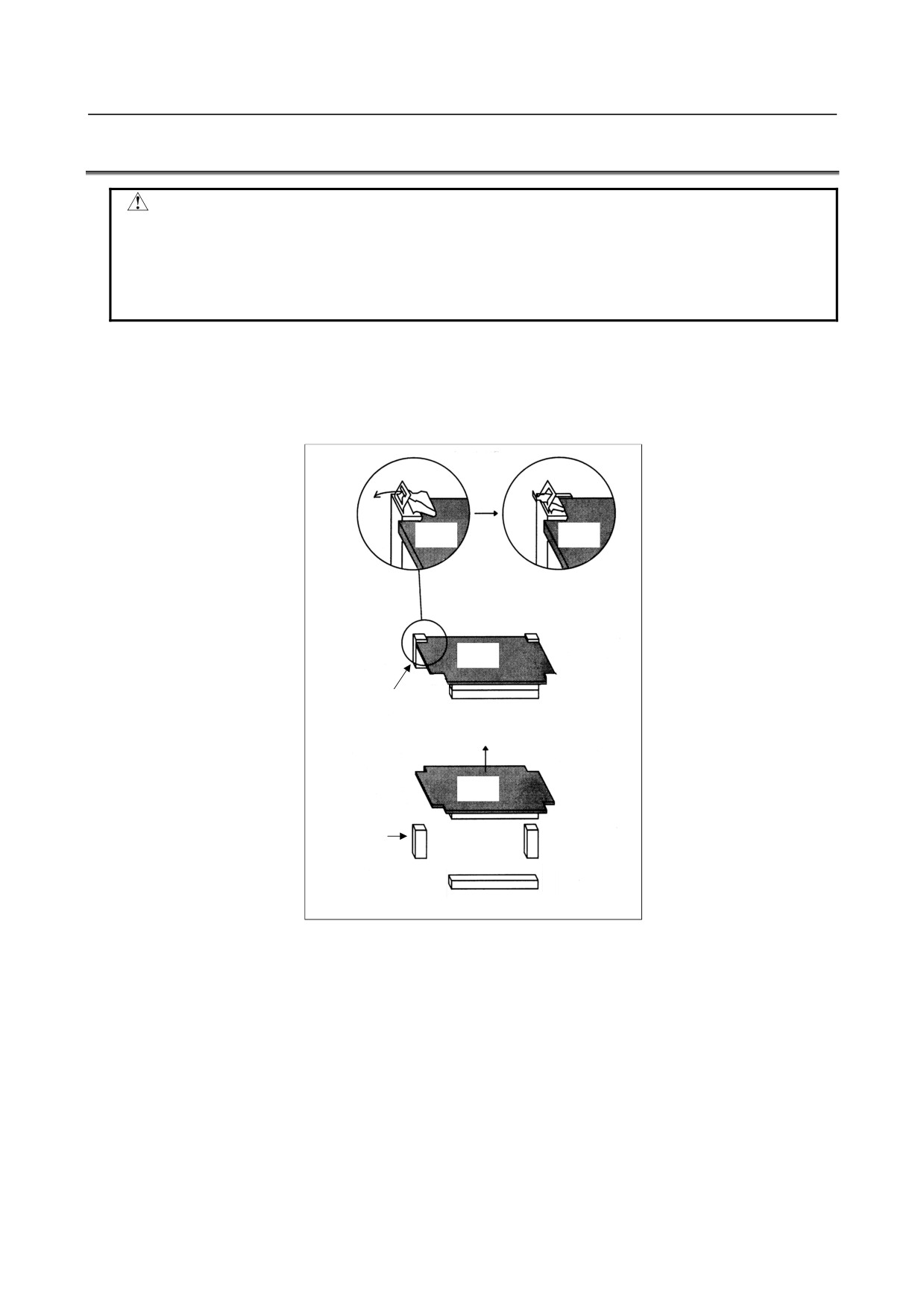
Method of extraction
1.
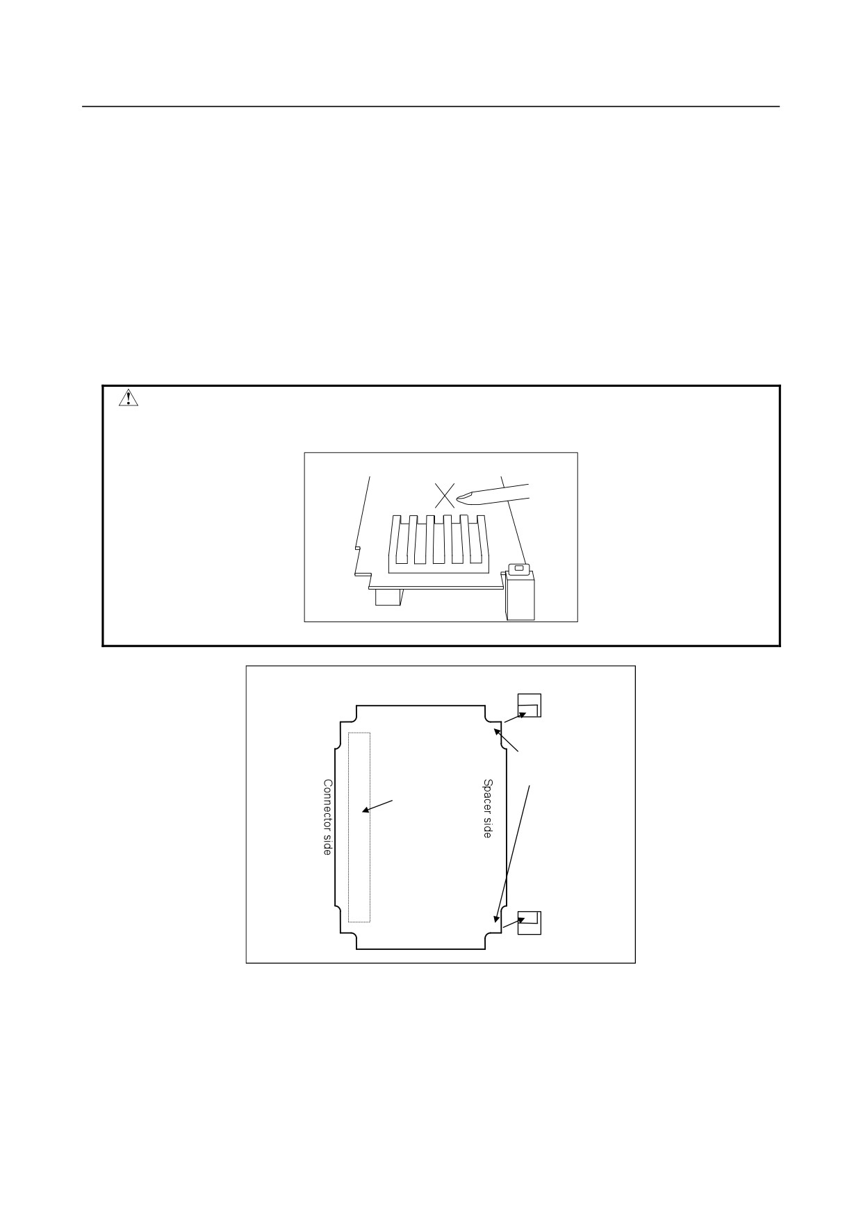
Unlatch the card PCB (servo card, CPU card, DeviceNet card, or GUI card) by pulling the claws on
the two spacers outward. (Fig. a)
2.
Pull the card PCB upward. (Fig. b)
Card PCB
Card PCB
Card PCB
Fig. a
Spacer
Connector
Card PCB
Spacer
Fig. b
Connector
- 259 -
3.REPLACING CONTROL UNIT MAINTENANCE PARTS
B-64485EN/01
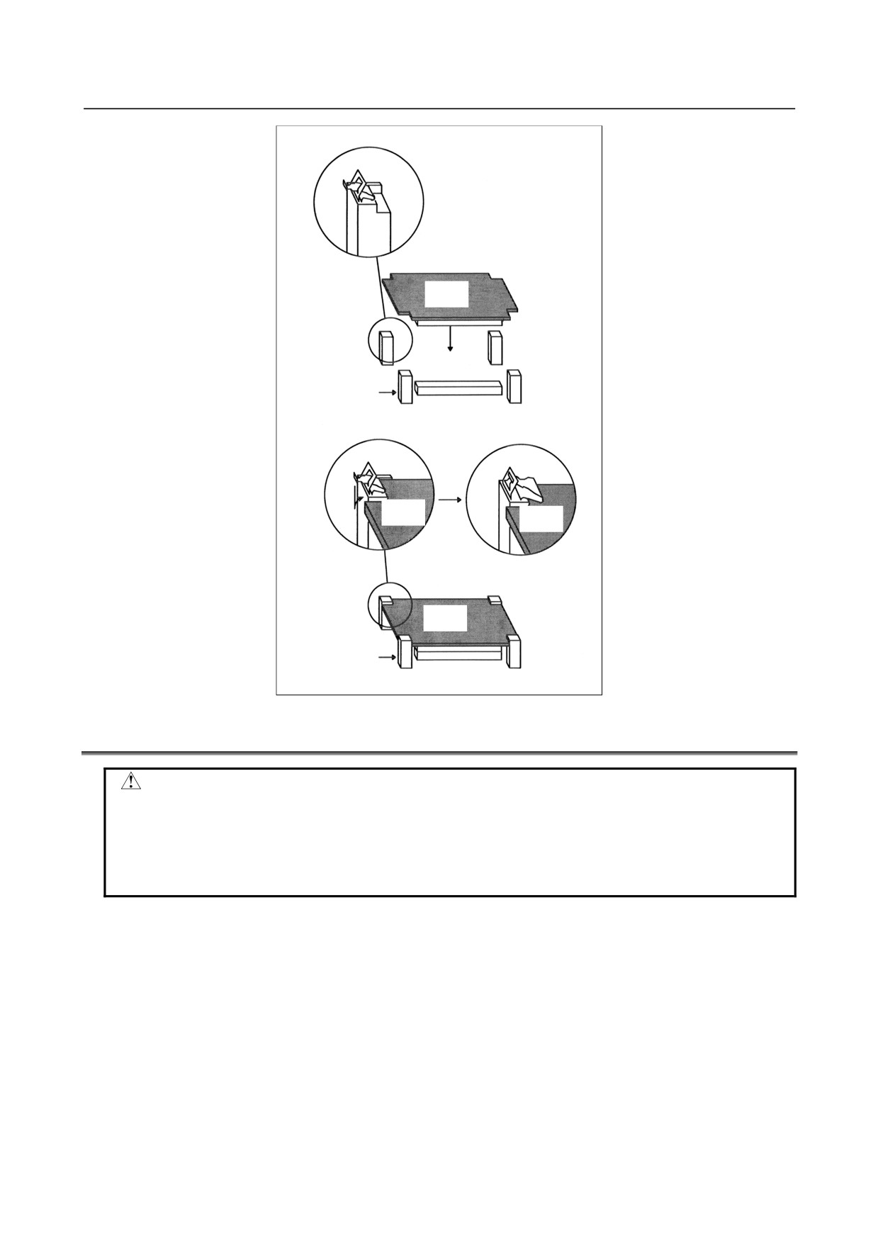
Method of insertion
1.
Check that the metal fittings of the spacers are raised. (Fig. d)
2.
To align the card PCB insertion position, touch the spacer fixing end faces of the card PCB with the
spacers as shown in the figure below. (At this time, the board can be touched with the spacers for
easier position alignment by slightly holding up the connector side and lowering the spacer side
only.)
3.
While aligning the card PCB with the spacers, lower the connector side slowly then cause the
connectors to touch each other. (Fig. d)
4.
Push the connector side of the card PCB slowly. At this time, push the card board against the board
on the rear side of the connector. The force required for connector insertion is about 10 kgf. If the
connector cannot be mated by a force of about 10 kgf or more, the card board may be aligned
incorrectly, and the connector can break. In this case, realign the card board.
5.
Push in the spacer metal fittings. (Fig. e)
CAUTION
When attaching the connector, do not press the radiating fin of the card PCB
with your finger, or you may get hurt or the PCB may get damaged.
Do not press the radiating fin of the card PCB with your finger.
Spacer
Spacer fixing
end face
Connector
on the back
Spacer
Fig. c
- 260 -
B-64485EN/01
3.REPLACING CONTROL UNIT MAINTENANCE PARTS
Card PCB
Fig. d
Spacer
Connector
Card PCB
Card PCB
Card PCB
Fig. e
Spacer
Connector
3.6
MOUNTING AND DEMOUNTING FROM/SRAM MODULE
CAUTION
Before starting replacement work, make a backup copy of the contents of the
FROM/SRAM module. See Chapter 5, “INPUT AND OUTPUT OF DATA”, and
Appendix C, “BOOT SYSTEM” for explanations about how to make backup
copies and how to restore the contents of memory. Also see Subsection 3.1.1,
“Optional Information File”.
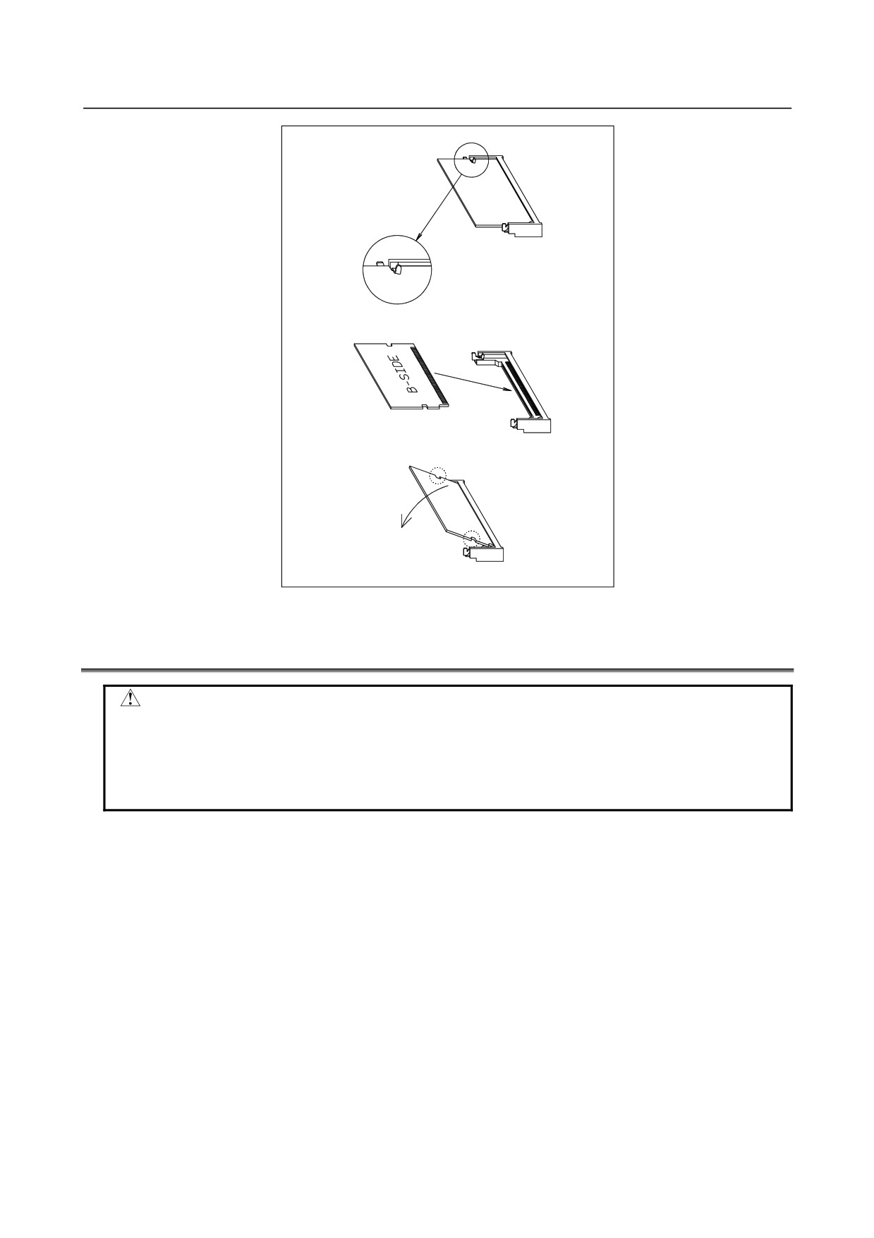
Demounting an FROM/SRAM module
1)
Open the claw of the socket outward. (Fig. a)
2)
Extract the module slantly upward. (Fig. b)
Mounting an FROM/SRAM module
1)
Insert the module slantly into the module socket, with side B facing upward. (Fig. b)
2)
Push the module downward until it is locked. (Fig. c) At this time, push it down with pushing two
points of (*) in the figure.
- 261 -
3.REPLACING CONTROL UNIT MAINTENANCE PARTS
B-64485EN/01
Fig. a
Fig. b
Fig. c
☆
☆
3.7
ATTACHING A COMPACT FLASH CARD ONTO, AND
DETACHING IT FROM, A PRINTED CIRCUIT BOARD
CAUTION
Before starting to replace the compact flash card, make a backup copy of the
contents (parameters, programs, etc.) of SRAM in the CNC. The SRAM contents
may be lost during replacement. See Chapter 5, “INPUT AND OUTPUT OF
DATA”, and Appendix C, “BOOT SYSTEM” for explanations about how to make
backup copies. Also see Subsection 3.1.1, “Optional Information File”.
Some types of printed circuit boards incorporate a compact flash card. When replacing these printed
circuit boards, stick to the following procedures.
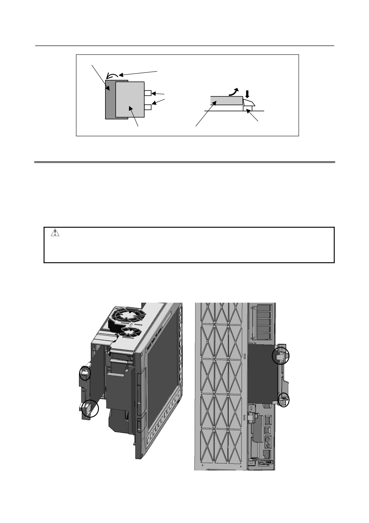
Dismounting procedure
Pull out the card by turning the latch toward the far side while pressing down the printed circuit board
retainer gently.
Mounting procedure
Push in the card until it locks.
- 262 -
B-64485EN/01
3.REPLACING CONTROL UNIT MAINTENANCE PARTS
Compact flash card socket
Latch
(2) Pull out the card
by lifting it up.
Retainer
(1) Press down the
retainer gently.
Board
Retainer
Compact flash card
3.8
INSERTING AND EXTRACTING OPTIONAL BOARDS
Method of extraction
1.
Detach the cable connected to the optional board and the cable that interferes when the optional
board is extracted.
2.
Pinch handles A and B.
3.
Pinch handle A, and extract the optional board while disengaging the latch.
Method of insertion
CAUTION
Insert the option board all the way through the rack. Turing on the power without
having it engaged with the back panel connector on the far-side wall of the rack
may lead to a failure or system alarm.
1.
By holding handles A and B, insert the board into the rack until it reaches the far-side wall of the
rack to make the back panel engaged with the connector. Make sure that the claw of handle A is
latched securely and the option board surface is flushed with the ambient surface.
2.
Plug the detached cables again correctly.
A
B
B
A
LCD-mounted type
Stand-alone type
- 263 -
3.REPLACING CONTROL UNIT MAINTENANCE PARTS
B-64485EN/01
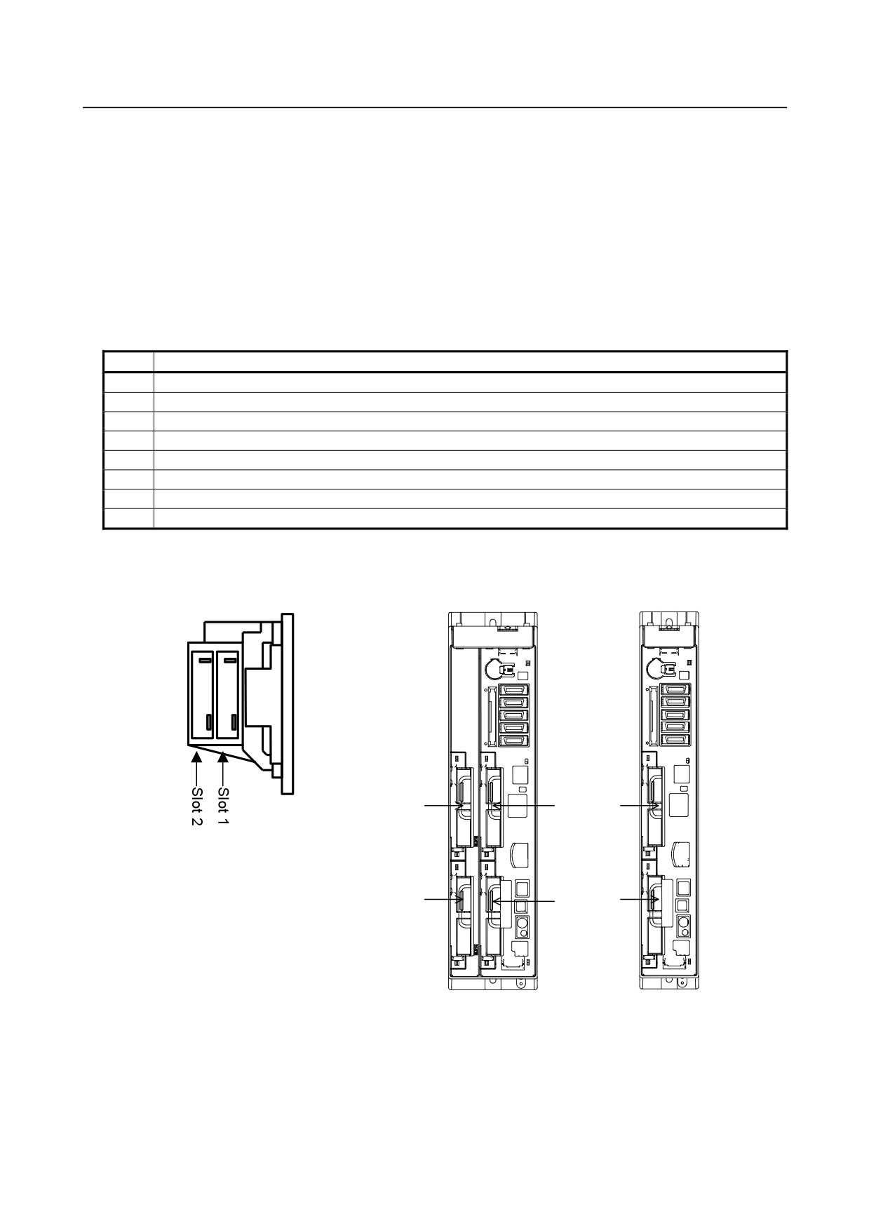
Option board location
Which slot is to be used for which option board is predetermined. When adding or maintaining option
boards, install them while observing the following rules.
1.
Option boards for 2-slot type LCD-mounted or stand-alone control units
Check the option boards you are going to install with Table 3.8.1. Insert a board with a smaller
number and that with a larger number, respectively, into slots 1 and 2.
2.
Option boards for 4-slot type stand-alone control units
Check the option boards you are going to install with Table 3.8.1. Insert a board with the smaller
number, one with the next smaller number, and so, respectively, into slots 1, 3, 4, and 2 in the stated
order.
Table 3.8.1 Optional boards
No.
Name
1
PROFIBUS-DP master board
2
Fast Ethernet board
3
DeviceNet master board
4
DeviceNet slave board
5
PROFIBUS-DP slave board
6
HSSB board
7
CC-Link remote device station board
8
Additional axis board
LCD-mounted type
Stand-alone type
4 slots
2 slots
Slot 1
Slot 3
Slot 2
Slot 4
- 264 -
B-64485EN/01
3.REPLACING CONTROL UNIT MAINTENANCE PARTS
3.9
REPLACING FUSES
WARNING
Before replacement of a blown fuse, the cause of the blown fuse must be
corrected. So, fuse replacement work must be done only by a person who is
trained in the related maintenance and safety requirements. When opening the
cabinet and replacing a fuse inside, be careful not to touch the high-voltage
circuits (marked with
and fitted with an insulating cover). Touching the
uncovered high-voltage circuits presents an extremely dangerous electric shock
hazard.
- 265 -
3.REPLACING CONTROL UNIT MAINTENANCE PARTS
B-64485EN/01
3.9.1
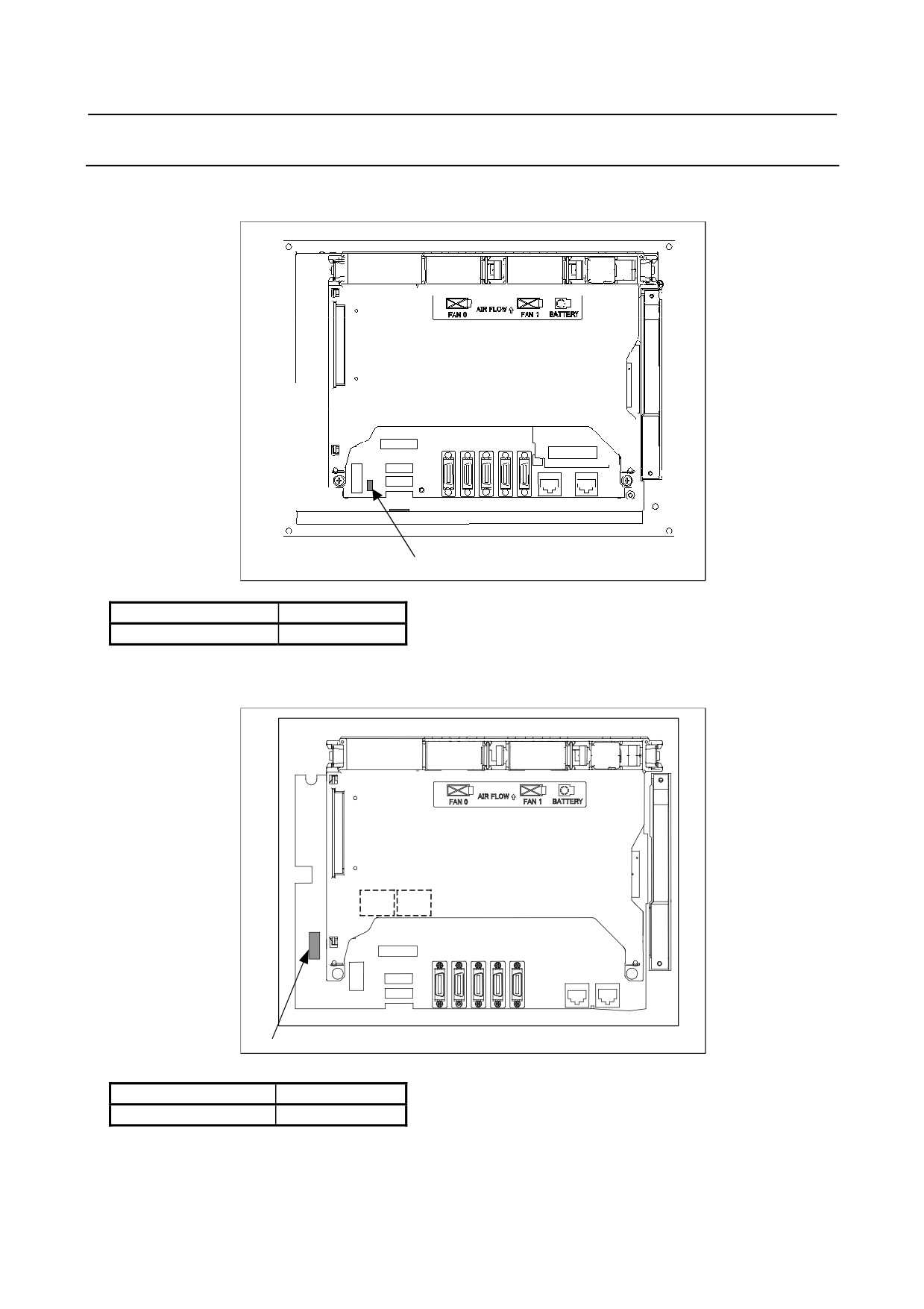
LCD-mounted Type Control Unit
・ 8.4” LCD unit and 10.4” LCD unit A
Fuse mounting location
Rear view
Fuse mounting location
Fuse specification
Specification
Rating
A02B-0236-K100
5A
・ 10.4” LCD unit and 15” LCD unit
Fuse mounting location
Rear view
Fuse mounting location
Fuse specification
Specification
Rating
A02B-0236-K101
7.5A
- 266 -
B-64485EN/01
3.REPLACING CONTROL UNIT MAINTENANCE PARTS
3.9.2
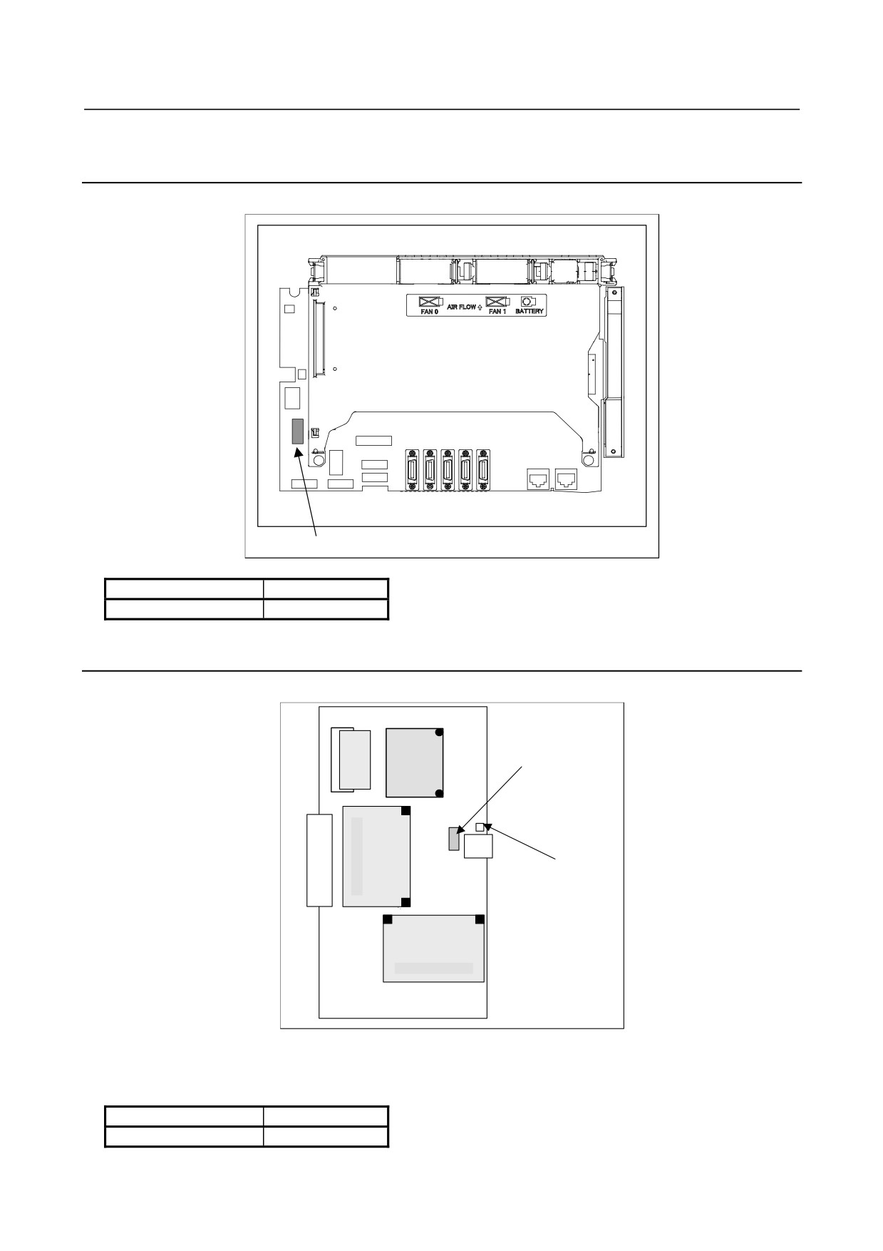
LCD-mounted Type Control Unit (Personal Computer
Function with Windows® CE)
Fuse mounting location
Rear view
Fuse
Fuse specification
Specification
Rating
A02B-0236-K101
7.5A
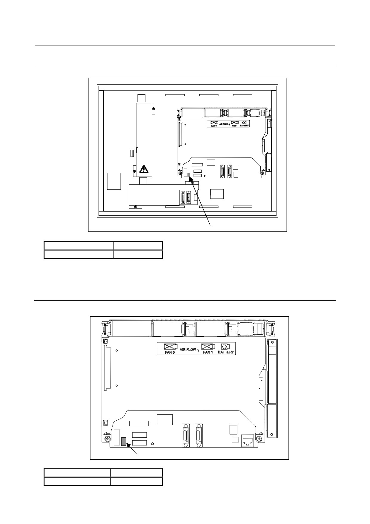
3.9.3
Stand-alone Type Control Unit
Fuse mounting location
Fuse
Fuse burn-out detection LED
Main board
The fuse is on the main board. Before replacing the fuse, pull out the main board. See Subsection 3.2.2
for explanations about how to pull it out.
Fuse specification
Specification
Rating
A02B-0265-K100
7.5A
- 267 -
3.REPLACING CONTROL UNIT MAINTENANCE PARTS
B-64485EN/01
3.9.4
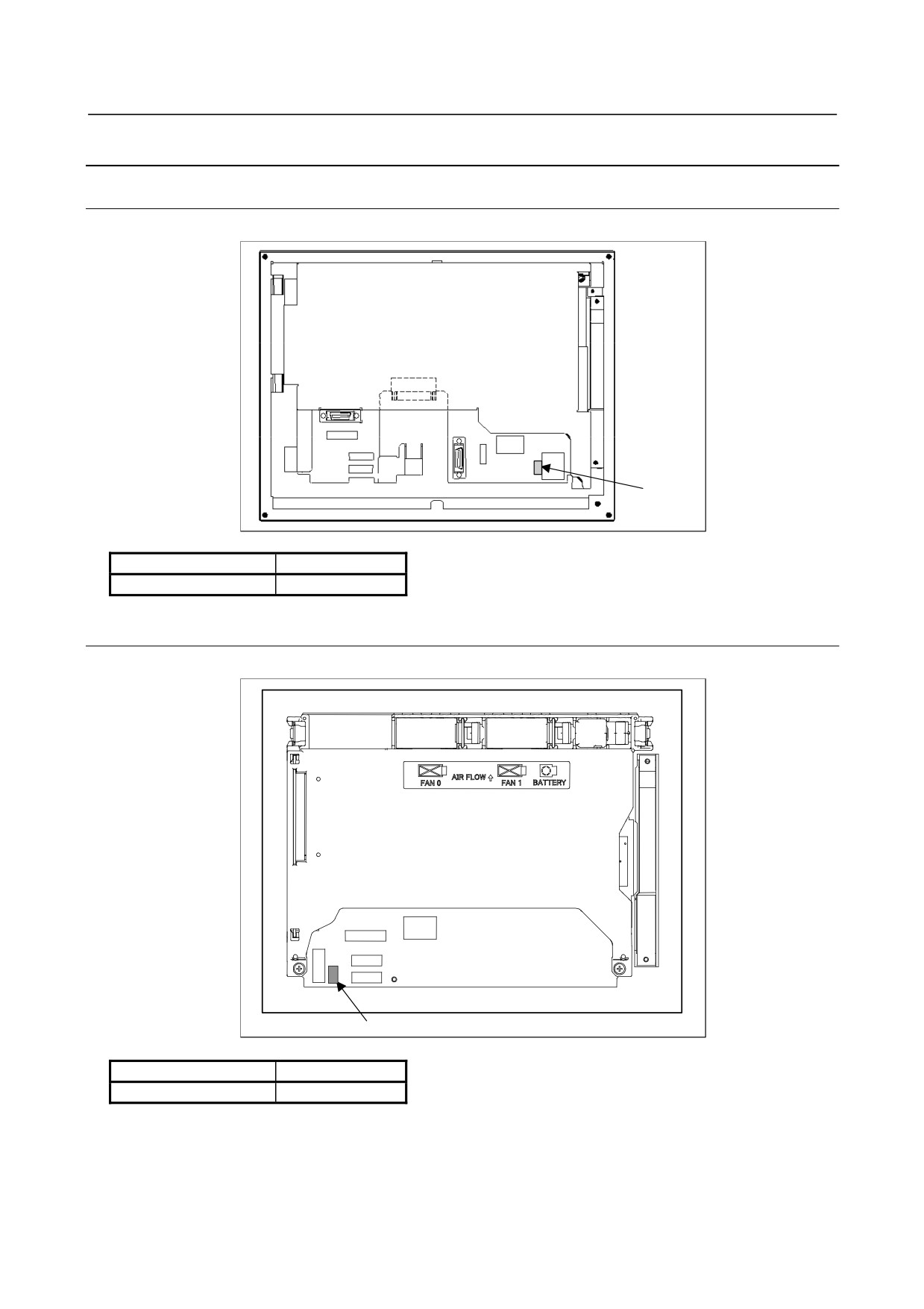
Display Unit for Stand-alone Type Control Unit
3.9.4.1 Display unit (10.4” LCD unit A)
Fuse mounting location
Fuse
Fuse specification
Specification
Rating
A02B-0303-K101
3.2A
3.9.4.2 Display unit (10.4” LCD unit B and 15” LCD unit)
Fuse mounting location
Rear view
COP21M
CA55
CPD18
Fuse
Fuse specification
Specification
Rating
A02B-0236-K100
5A
- 268 -
B-64485EN/01
3.REPLACING CONTROL UNIT MAINTENANCE PARTS
3.9.4.3 Display unit for Automotive manufacture
Fuse mounting location
Rear view
Fuse
Fuse specification
Specification
Rating
A02B-0236-K100
5A
3.9.5
Replacing the Fuse on the Display Unit for the Stand-Alone
Type Control Unit (with PC Functions Supporting Windows®
CE)
Fuse mounting location
Rear view
Fuse
Fuse specification
Specification
Rating
A02B-0236-K100
5A
- 269 -
3.REPLACING CONTROL UNIT MAINTENANCE PARTS
B-64485EN/01
3.10 REPLACING THE MEMORY BACKUP BATTERY IN THE
CONTROL UNIT
Such as Offset data and system parameters are stored in SRAM in the control unit. The power for the
SRAM is backed up with a memory backup battery housed in the control unit. Therefore, the above data
is not lost even if the main power is turned off.
When the battery voltage falls, alarm message "BAT" blinks on the LCD screen and the battery alarm
signal is output to the PMC. Once the alarm message starts blinking or the alarm signal is output, replace
the battery as soon as possible. In general, the battery can be replaced within one week of the alarm first
being issued. This, however, depends on the system configuration.
If the battery voltage subsequently drops further, backup of memory can no longer be provided. Turning
on the power to the control unit in this state causes system alarm to be issued because the contents of
memory are lost. Replace the battery, clear the entire memory, then reenter the data.
For this reason, FANUC recommends that the battery be replaced once per year regardless of whether a
battery alarm is issued.
Two types of batteries are usable:
• Lithium battery incorporated in the control unit
• Commercial alkaline dry cells (R20) inserted in a battery case externally attached to the control unit
NOTE
The control unit is factory-equipped with a lithium battery by default. This battery
can provide backup for the memory contents for about a year.
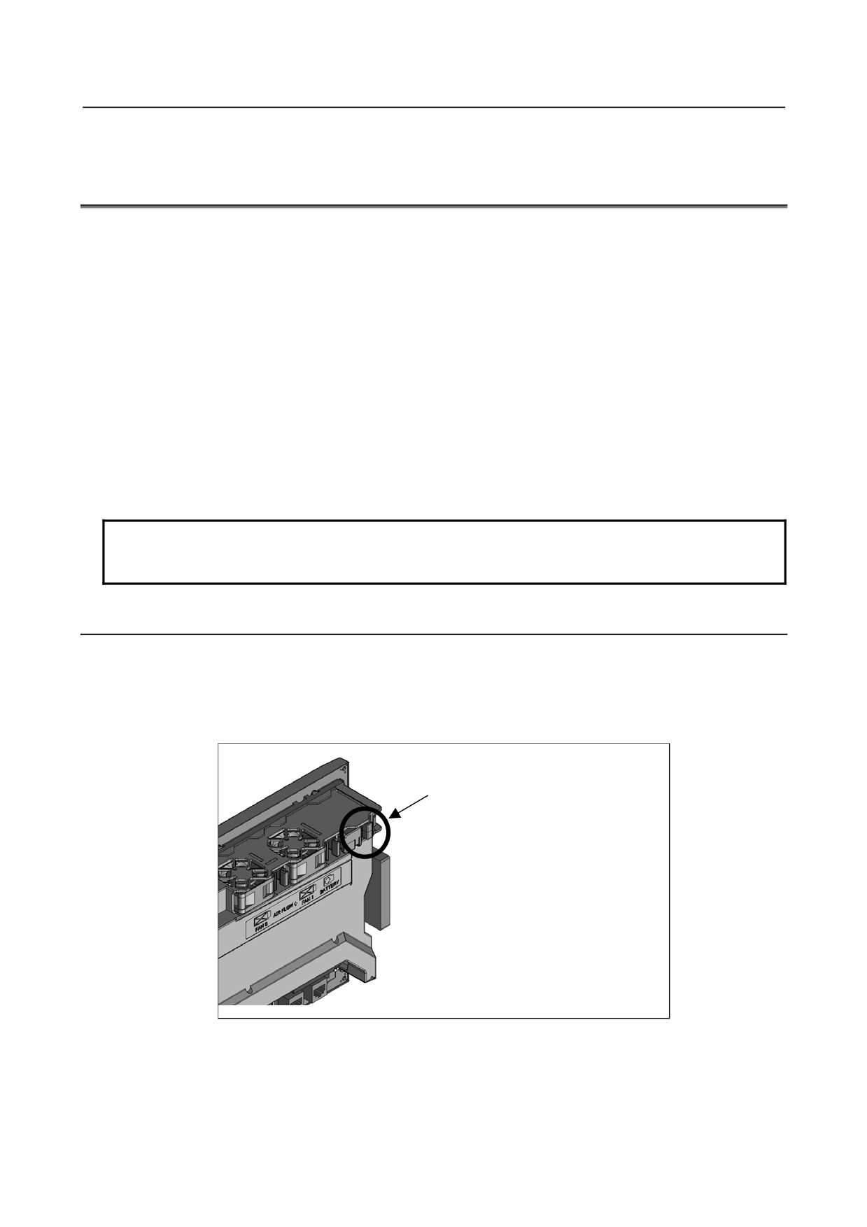
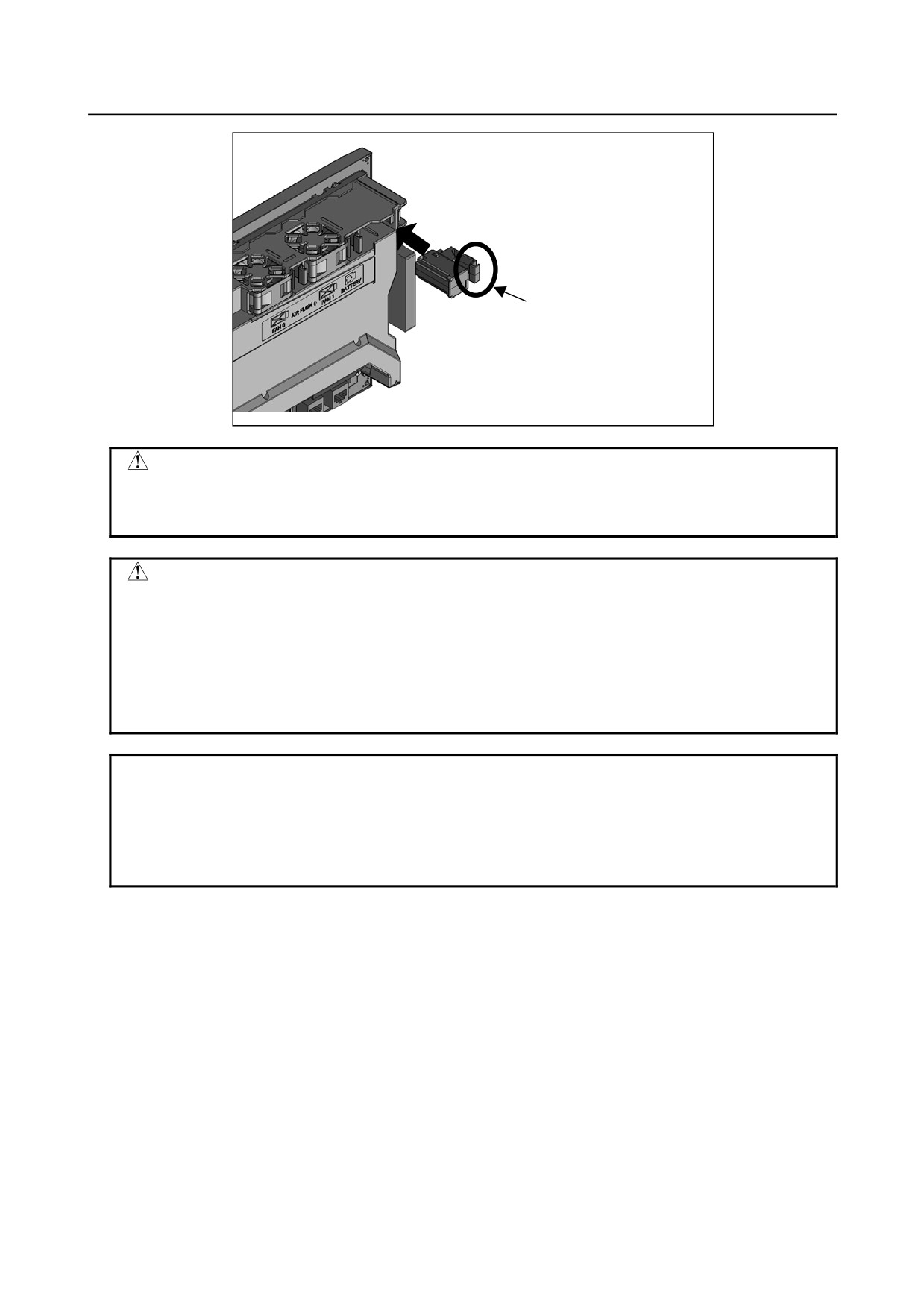
3.10.1 Replacing a Lithium Battery
For LCD-mounted type control unit
Prepare a new lithium battery (ordering code: A02B-0323-K102).
<1> Turn the power to the machine (control unit) on. After about 30 seconds, turn the power off.
<2> Pull out the lithium battery on the back of the control unit. (Hold the latch of the lithium battery, and
pull the lithium battery toward you while releasing the claw from the case.)
While holding this section, pull out the battery.
<3> Mount a new lithium battery you get ready beforehand. (Push the battery until the catch is latched
with the case.) Confirm that the catch has been latched securely.
- 270 -
B-64485EN/01
3.REPLACING CONTROL UNIT MAINTENANCE PARTS
Push the battery until the
catch is latched with the
case.
WARNING
Using other than the recommended lithium battery may result in the battery
exploding. Replace the battery only with the specified lithium battery
(A02B-0323-K102).
CAUTION
Steps <1> to <3> should be completed within 30 minutes.
Do not leave the control unit without a battery for any longer than the specified
period. Otherwise, the contents of SRAM may be lost.
Before starting replacement work, save the contents of the SRAM in a batch.
Even if they are lost, they can be restored easily.
For the methods of saving all contents and restoring them, refer to the Chapter
5, “INPUT AND OUTPUT OF DATA”, and Appendix C, “BOOT SYSTEM”.
NOTE
After replacement, dispose the used battery as “industrial waste” correctly
according to the laws of the country where the machine is installed and the
ordinances of the local government having jurisdiction over the site of the
machine. When disposing the battery, insulate it, for example, by taping its
electrodes in order to prevent a short circuit.
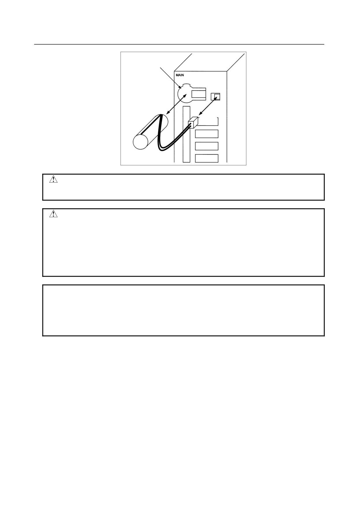
For stand-alone type control unit
Prepare a new lithium battery (ordering code: A02B-0200-K102).
<1> Turn the power to the machine (control unit) on. After about 30 seconds, turn the power off.
<2> Remove the lithium battery on the upper section of the control unit.
First, unplug the connector by yanking the battery cable, then take the battery out of its case.
The battery case is located in the upper section of the face plate of the main board.
<3> Insert a new lithium battery and reconnect the connector.
- 271 -
3.REPLACING CONTROL UNIT MAINTENANCE PARTS
B-64485EN/01
Battery case
Lithium battery
A02B-0200-K102
Connector
WARNING
Using other than the recommended battery may result in the battery exploding.
Replace the battery only with the specified battery (A02B-0200-K102).
CAUTION
Steps <1> to <3> should be completed within 30 minutes.
Do not leave the control unit without a battery for any longer than the specified
period. Otherwise, the contents of SRAM may be lost.
Before starting replacement work, save the contents of the SRAM in a batch.
Even if they are lost, they can be restored easily.
For the methods of saving all contents and restoring them, refer to the Chapter
5, “INPUT AND OUTPUT OF DATA”, and Appendix C, “BOOT SYSTEM”.
NOTE
After replacement, dispose the used battery as “industrial waste” correctly
according to the laws of the country where the machine is installed and the
ordinances of the local government having jurisdiction over the site of the
machine. When disposing the battery, insulate it, for example, by taping its
electrodes in order to prevent a short circuit.
- 272 -
B-64485EN/01
3.REPLACING CONTROL UNIT MAINTENANCE PARTS
3.10.2 Replacing a Commercial D-size Alkaline Dry Cells
Commercial alkaline dry cells (R20) can be used in place of the lithium battery incorporated in the control
unit by inserting them in a battery case externally attached to the control unit.
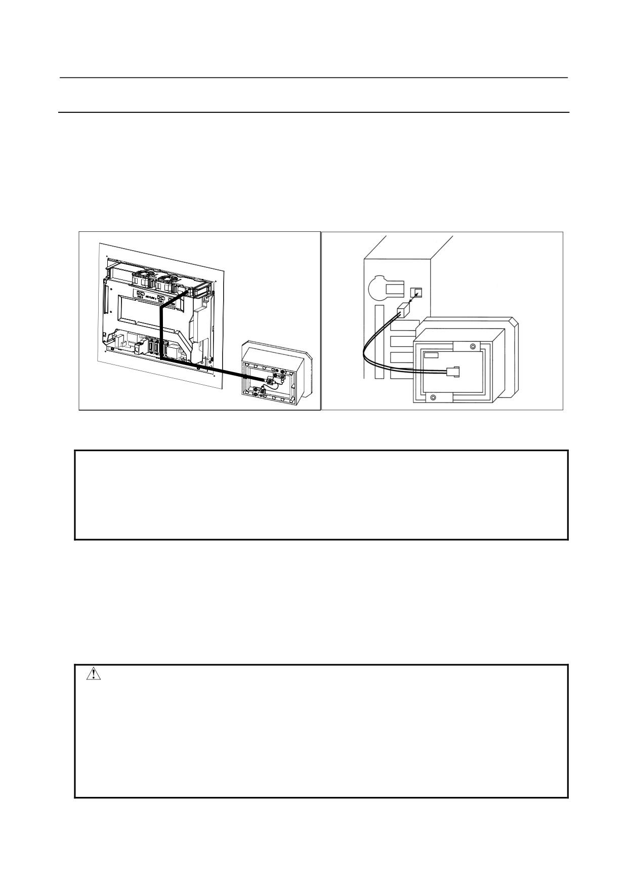
How to connect the battery case to the control unit
For the LCD-mounted type control unit, attach a battery cable (A02B-0323-K103) to the battery case
(A02B-0236-C282). For the stand-alone control unit, use the battery case (A02B-0236-C281), which is
factory-attached with a battery cable.
(For LCD-mounted type)
(For stand-alone type)
Example of connecting the battery case to the control unit
NOTE
1 The connector of the battery cable has a simplified lock for engagement. So, fix
the battery cable at a point within a length of 500 mm from the connector
location with no tension on it in order to prevent the connector from falling due to
its own weight or any extraneous force.
2 Keep the battery cable away from any source of noise, such as power wires.
Replacing a commercial D-size alkaline dry cells
<1> Have commercial D-size alkaline dry cells handy.
<2> Turn the power to the machine (control unit) on for about 30 seconds.
<3> Turn off the power to the control unit.
<4> Remove the cover from the battery case.
<5> Replace the old dry cells with new ones. Mount the dry cells in a correct orientation.
<6> Reinstall the cover onto the battery case.
CAUTION
Steps <1> to <6> should be completed within 30 minutes.
Do not leave the control unit without a battery for any longer than the specified
period. Otherwise, the contents of SRAM may be lost.
If steps <1> to <6> may not be completed within 30 minutes, save all contents of
the SRAM to the memory card or USB memory beforehand. Thus, if the contents
of the SRAM are lost, the contents can be restored easily.
For the methods of saving all contents and restoring them, refer to the Chapter
5, “INPUT AND OUTPUT OF DATA”, and Appendix C, “BOOT SYSTEM”.
- 273 -
3.REPLACING CONTROL UNIT MAINTENANCE PARTS
B-64485EN/01
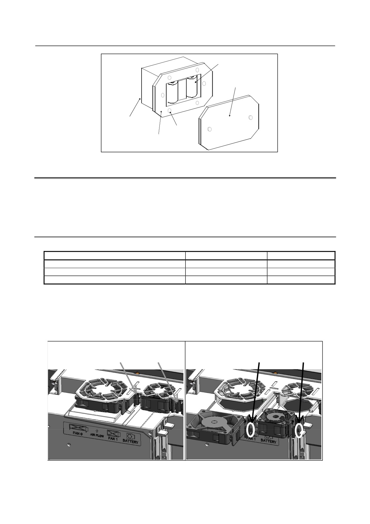
2 dry cells
Cover
Connection terminal
on the back
4 mounting
holes
Case
3.11 REPLACING A FAN
When a reduction in the speed of the fan motor is detected, the FAN warning message blinks on the LCD
screen.
When a failure such as stop of the fan motor is detected, an overheat alarm or system alarm is issued and
the system stops operating. Therefore, as soon as the FAN warning appears, replace the fan motor.
3.11.1 LCD-mounted Type Control Unit
-
Fan motor specification
Specification
Remark
Unit with no option slot
A02B-0323-K120
Unit with a slot for option 1
A02B-0323-K124
Unit with a slot for option 2
A02B-0323-K125
-
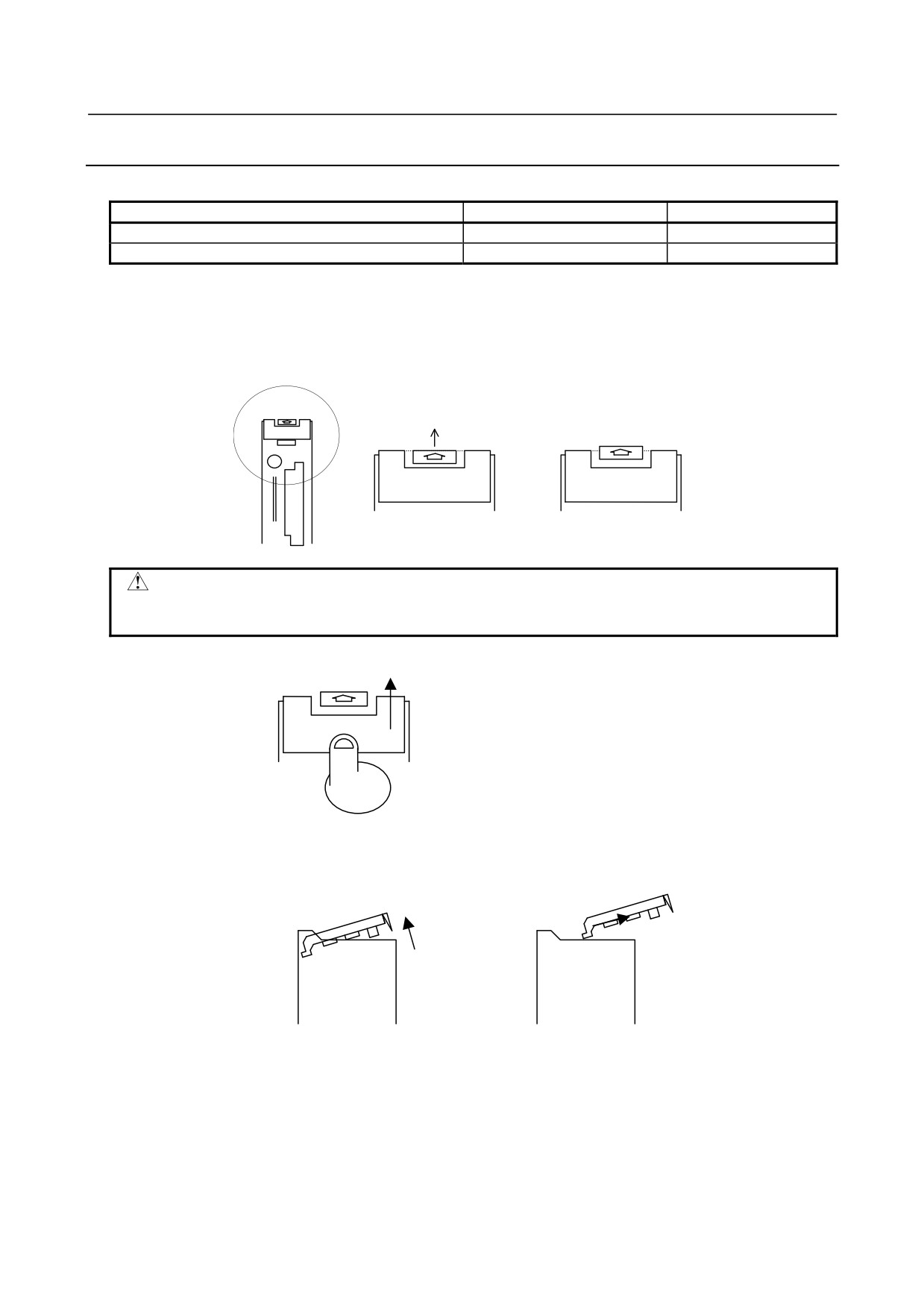
Replacing a fan motor
1.
When replacing the fan motor, be sure to turn off the power to the machine (CNC).
2.
Remove the fan motor from the case by holding its latch and pulling it out while releasing the claws
from the case.
3.
Mount the fan motor to the case. After that, make sure that the fan motor claws have latched the case
securely.
To remove the fan motor, hold the latches
When mounting the fan motor, push it in
of the fan motor and pull it out.
until its claws latch the case.
- 274 -
B-64485EN/01
3.REPLACING CONTROL UNIT MAINTENANCE PARTS
3.11.2 Stand-alone Type Control Unit
-
Fan unit specification
Specification
Remark
2-slot rack fan unit
A02B-0303-C103
4-slot rack fan unit
A02B-0303-C102
-
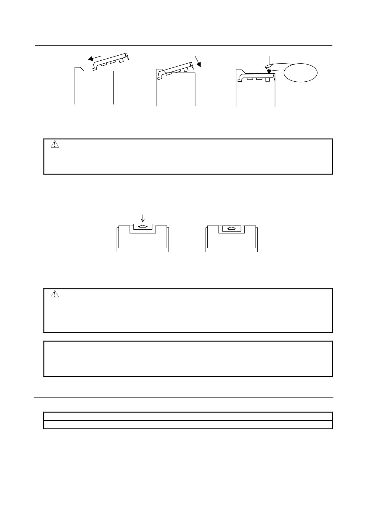
Replacing a fan unit
Detaching a fan unit
1.
When replacing the fan motor, be sure to turn off the power to the machine (control unit).
2.
Push up the latch at the top of the unit until the latch is disengaged.
Push up the latch.
Latched
Unlatched
CAUTION
Just disengage the latch. Do not push up the latch after the latch is disengaged.
If you continue pushing up the latch forcibly, the latch can break.
3.
Place a finger at the bottom of the front of the fan unit then push up the fan unit.
Push up the fan unit.
4.
Push up the fan unit until the fan unit is slanted by about 30 degrees.
5.
Pull out the fan unit toward you in the slanted direction.
4. Push up the fan unit until it is
5. Pull out the fan unit toward you
slanted by about 30 degrees.
in the slanted direction.
Attaching a fan unit
1.
Insert a fan unit deeply into the main unit at a slanted angle of about 30 degrees until the fan unit
touches the wall of the main unit.
2.
Lower the fan unit slowly on the main unit.
3.
Push down the fan unit on the near side to couple the fan unit with the top of the main unit.
- 275 -
3.REPLACING CONTROL UNIT MAINTENANCE PARTS
B-64485EN/01
1. Insert the fan unit at about 30
2. Lower the fan unit slowly.
3. Push down the fan unit to
degrees until it touches the
connect it to the main unit.
far-side wall of the main unit.
CAUTION
The fan unit and main board are coupled directly with each other by a connector.
When mounting the fan unit, failing to follow the connection procedure correctly
may damage the coupling section of the connector.
4.
Push down the latch at the top of the fan unit for latching.
4. Push down the latch.
Unlatched
Latched
5.
Turn on the power, then check that no fan alarm is issued and that both fans are rotating.
CAUTION
If the power is turned on without connecting the fan unit correctly, it is likely that
the fan may not be able to rotate or a fan alarm may be issued even when it
rotates. After replacement, make sure that the fan rotates normally and no fan
alarm is issued.
NOTE
When a large amount of force is required to couple the fan unit with the main
unit, check if pins of the connector of the base printed circuit board are bent and
if the base printed circuit board is inserted correctly.
3.11.3 Display Unit for Automotive
-
Fan motor specification
Specification
Remark
A02B-0323-K120
-
Replacing a fan motor
See Subsection 3.11.1 for explanations about how to replace the fan motor.
- 276 -

B-64485EN/01
3.REPLACING CONTROL UNIT MAINTENANCE PARTS
3.11.4 Display Unit for Stand-alone Type Control Unit (Personal
Computer Function with Windows® CE)
-
Fan motor specification
Specification
Remark
A02B-0323-K120
-
Replacing a fan motor
See Subsection 3.11.1 for explanations about how to replace the fan motor.
- 277 -
3.REPLACING CONTROL UNIT MAINTENANCE PARTS
B-64485EN/01
3.12 REPLACING THE PROTECTION COVER
-
Protection cover specification
Screen size
Specification
Remark
8.4”
A02B-0323-K112
10.4”
A02B-0323-K113
12.1”
A02B-0323-K114
15”
A02B-0323-K115
-
How to attach the protection cover
If the screen surface already has a protection cover or touch panel protection sheet attached on it, detach the
cover or sheet from it. Remove any adhesive left on it completely, using adhesive tape. Using solvent in
attempt to remove any remaining adhesive may result in the screen surface being soiled contrary to your
expectation.
Before attaching the protection cover, wipe off any soil and smear completely from the ornamental frame,
LCD surface, and soft key surface, using ethanol or diluted neutral detergent (such as kitchen detergent). If
you used neutral detergent, remove any remaining detergent, using a cloth wetted with water. Any remaining
oily substance or detergent causes the protection cover to come off easily. After making sure that the
ornamental frame is dry, follow the procedure below to attach the protection cover.
-
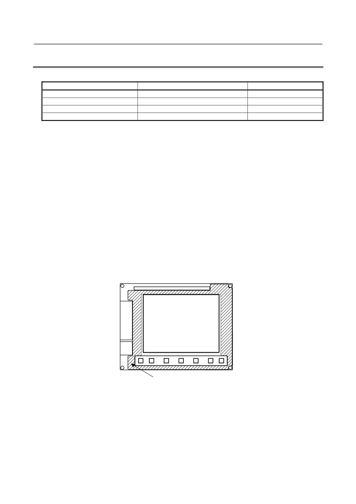
For 8.4” LCD unit
1.
Position the protection cover in such a way that the both-side adhesive tape does not overlap with
the soft key section, LCD section, PCMCIA interface or USB port lids.
2.
Upon completion of positioning, press the protection cover by stroking the both-side adhesive tape
section. Moving your finger along the attached surface with a short reciprocating motion can
enhance adhesion.
3.
The protection cover surface is covered with a thin film to protect it from flaws and contamination.
Peel off the thin film from the protection cover.
Both-side adhesive tape (hatched)
-
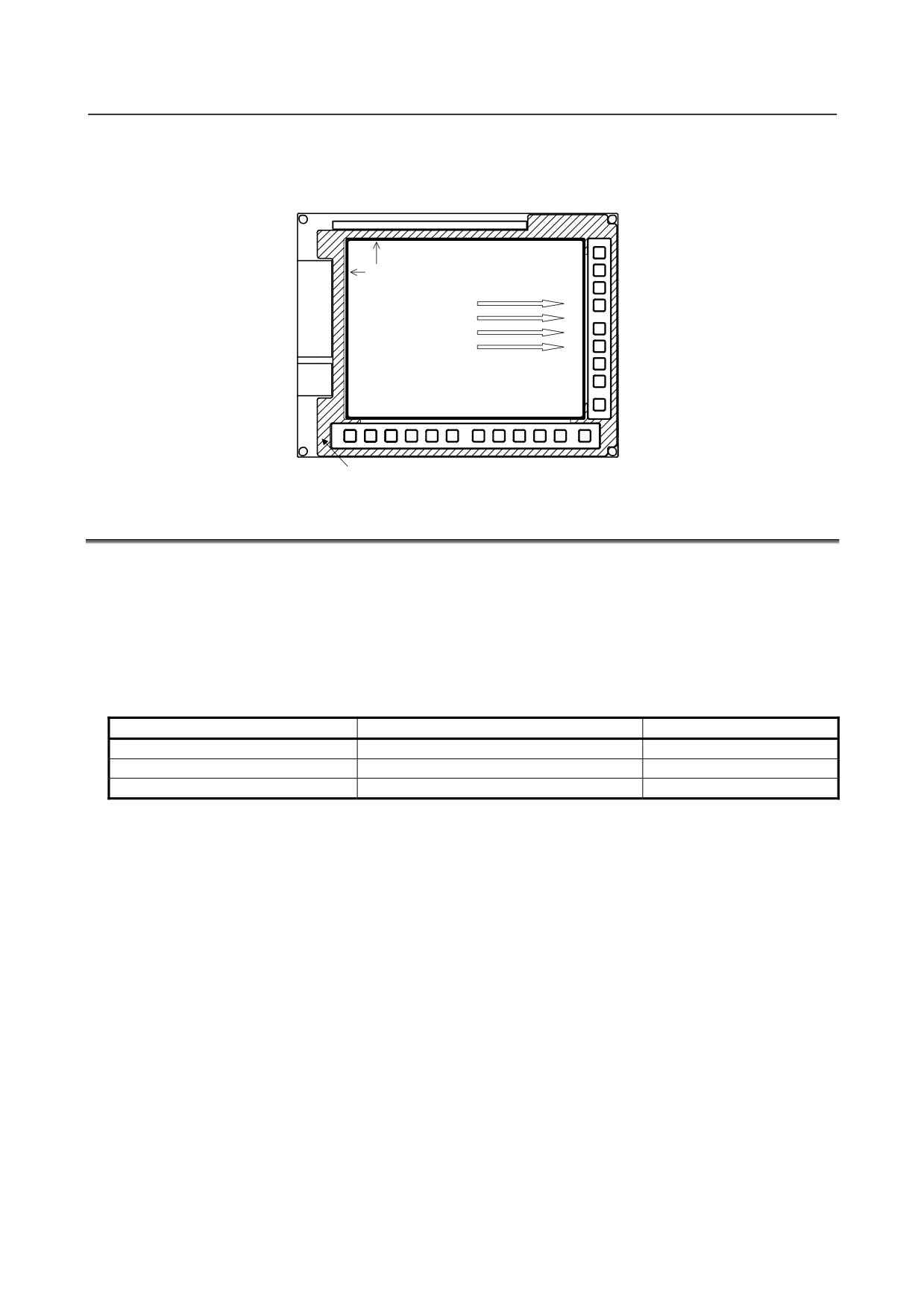
For 10.4”, 12.1”, and 15” LCD units
1.
The protection cover for the LCD units has a concave section so that it is conformable to the figure
of the display section. Position the protection cover in such a way that the concave section meets the
ornamental frame at the position indicated with the arrow while exercising care not to cause the
both-side adhesive tape to overlap with the soft key section.
2.
Pressing the protection cover after positioning in such a way that any air left between the LCD
section and protection cover is expelled toward the right will make it possible to attach the
protection cover tidily. Once the protection cover is finally positioned, press it firmly while stroking
the both-side adhesive tape section. Moving your finger along the attached surface with a short
reciprocating motion can enhance adhesion.
- 278 -
B-64485EN/01
3.REPLACING CONTROL UNIT MAINTENANCE PARTS
3.
For units with a touch panel, make sure that the touch panel is not held pressed after power-on. Also
make sure that the touch panel works normally.
1.Alignment position
2.Expel air toward the right.
Both-side adhesive tape (hatched)
3.13 REPLACING THE TOUCH PANEL PROTECTION SHEET
For the unit with a touch panel, the surface of the touch panel is covered with the protection sheet to
protect it. When there are flaws and contamination on this protection sheet that make the screen hard to
read, replace the protection sheet. Prepare the following items.
1)
Protection sheet
2)
Ethanol or neutral detergent (such as kitchen detergent)
3)
Soft cloth (if neutral detergent is used)
Touch panel protection sheet specification
Screen size
Specification
Remark
10.4”
A02B-0236-K110
12.1”
A02B-0236-K118
15”
A08B-0082-K020
-
Replacement procedure
1)
Before replacement
<1> Turn off the power to the machine.
<2> Peel off the old protection sheet from the surface of the touch panel.
<3> Remove any remaining adhesive completely, using adhesive tape.
Using solvent in attempt to remove any remaining adhesive may result in the screen surface
being soiled contrary to your expectation.
<4> Remove any oily substance from the touch panel surface, using ethanol or diluted neutral
detergent.
<5> If you used neutral detergent, remove any remaining detergent, using a soft cloth wetted with
water.
→ If the touch panel surface becomes cloudy, oil is still left on the surface. Remove oil
completely.
→ If oil or detergent is left on the surface of the touch panel, the protection sheet cannot
adhere to the panel completely and will sometimes peel off easily.
<6> With a dry soft cloth, wipe off moisture completely.
- 279 -
3.REPLACING CONTROL UNIT MAINTENANCE PARTS
B-64485EN/01
2)
Applying the protection sheet
<1> Fold the tab over the front side (the side opposite to the backing sheet).
Fold
<2> Peel off the backing sheet.
<3> Position the sheet, then attach the upper and lower sides of the sheet first. Check that the sides
of the protection sheet do not touch the escutcheon.
OK
NG
<4> Attach the right and left sides of the protection sheet while pushing out air between the touch
panel and protection sheet.
→ With part of the protection sheet kept stuck to the touch panel, do not attempt to correct
the position of the protection sheet by pulling the sheet.
<5> Press the adhesive parts of the four sides, and attach the entire sheet completely.
→ Check that the four corners and four sides of the protection sheet do not float.
(3) Checks after replacement
<1> Check that there is no wrinkle on the surface of the protection sheet.
<2> After power-on, check that there is no touch panel portion kept pressed.
<3> Press the touch panel, and check that correct operation takes place.
3.14 TOUCH PANEL CALIBRATION
-
Conditions that require calibration
Touch panel calibration is needed under the following conditions:
1.
The LCD mounted type control unit with a touch panel or the display unit with a touch panel was
replaced.
2.
The main board on the LCD mounted type control unit with a touch panel or the display control
board on the display unit with a touch panel was replaced.
3.
The touch panel control board was replaced.
4.
Memory all clear was performed.
-
Related Parameters
#7
#6
#5
#4
#3
#2
#1
#0
3113
DCL
[Input type] Parameter input
[Data type] Bit
#5 DCL The touch panel compensation screen is:
0: Disabled.
1: Enabled.
Set this parameter to 0 usually. Touch panel compensation becomes necessary only when
the panel is replaced or memory all clear operation is performed. Set this parameter to 1
only when performing touch panel compensation. Upon completion of compensation, set
this parameter to 0.
- 280 -
B-64485EN/01
3.REPLACING CONTROL UNIT MAINTENANCE PARTS
#7
#6
#5
#4
#3
#2
#1
#0
3119
TPA
DDS
[Input type] Parameter input
[Data type] Bit
NOTE
When this parameter is set, the power must be turned off before
operation is continued.
#2 DDS The touch panel is:
0: Enabled.
1: Disabled.
Set this parameter to 1 when disabling the touch panel temporarily, for example, at
start-up time.
-
Touch panel calibration method
NOTE
How to calibrate the touch panel used with the display unit for the LCD-mounted
control unit (with personal computer function with Windows® CE) and the
stand-alone control unit (with personal computer function with Windows® CE) or
the display unit for automobile manufacturers is explained later.
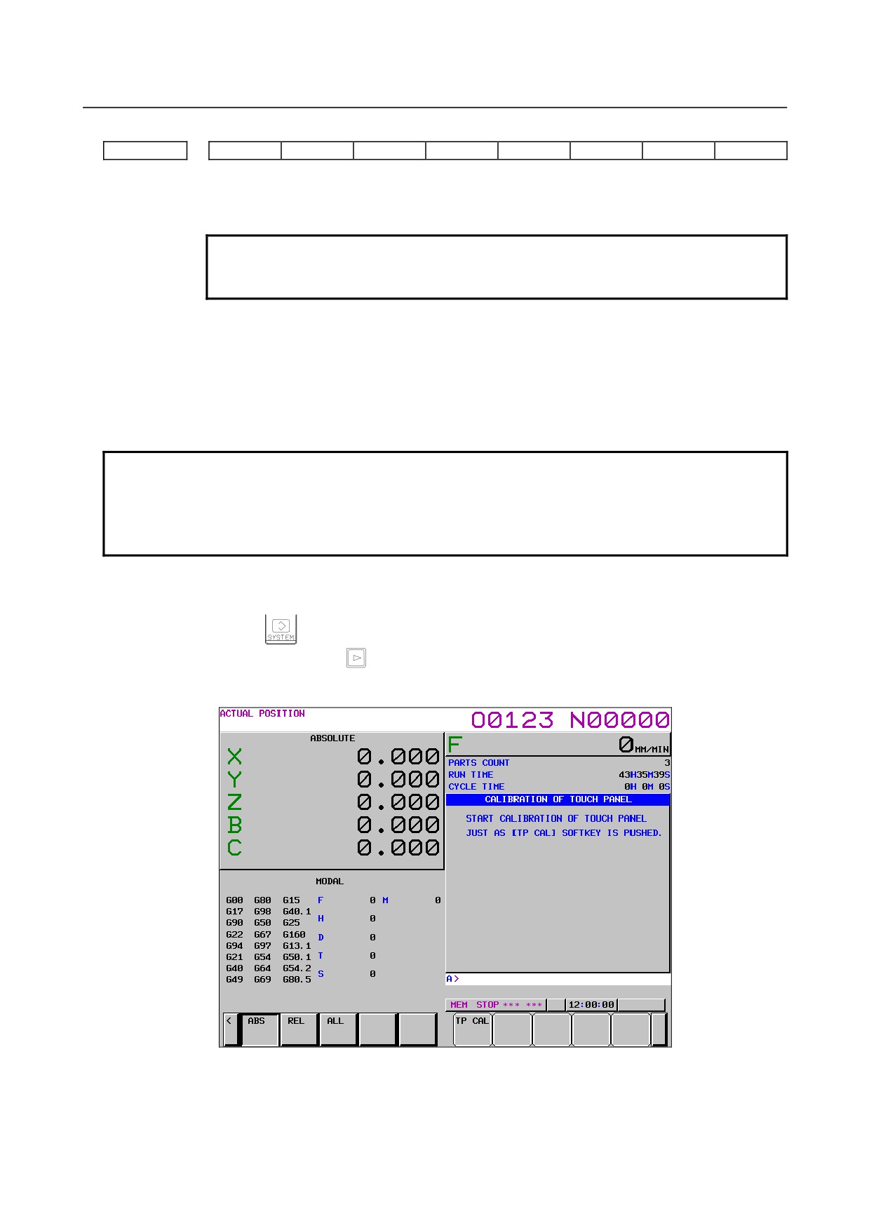
Calibration procedure
<1> Enable the touch panel calibration screen.(Set bit 5 (DCL) of parameter No. 3113 to 1.)
<2> Press function key
<3> Press the continuous menu key
several times. The [TOUCH PANEL] soft key is displayed.
<4> Press the [TOUCH PANEL] soft key then the [(OPRT)] soft key. The [TP CAL] soft key is
displayed.
- 281 -