FANUC Series 30i-MODEL B, 31i-MODEL B, 32i-MODEL B. MAINTENANCE MANUAL - page 7
2.CONTROL UNIT HARDWARE
B-64485EN/01
2.2.2
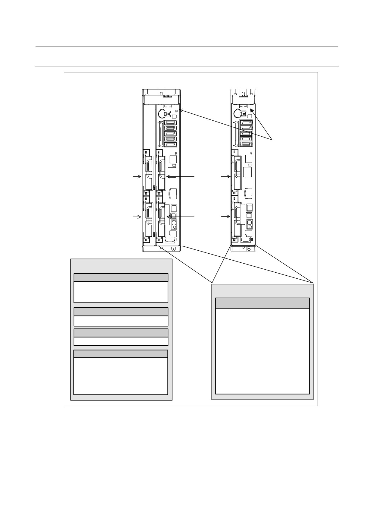
Stand-alone Type Control Unit Overview
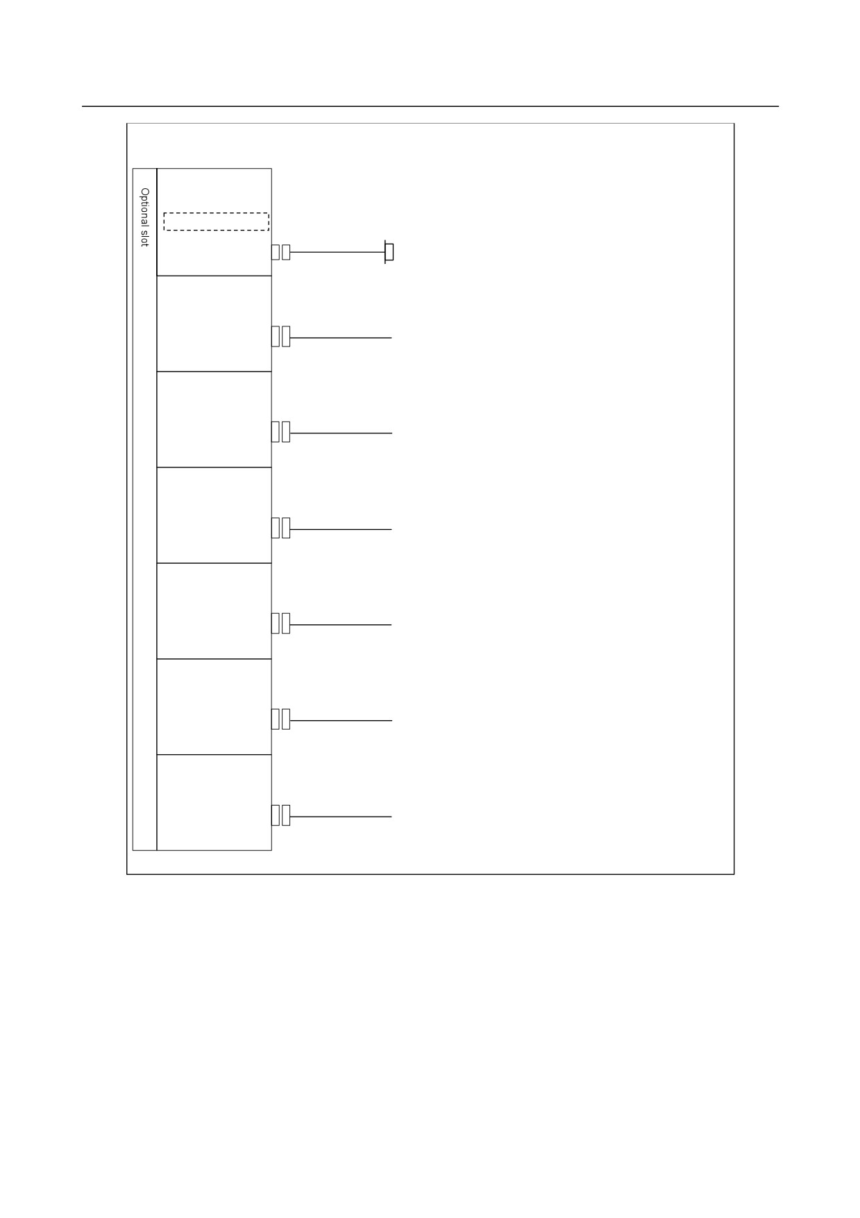
4-slot rack
2-slot rack
Main board
Slot 3
Slot 1
Slot 4
Slot 2
Options (Slot 1 to 4)
Fast Ethernet board
Fast Ethernet function
Data server function
Basic system
FL-net function
Main board
Additional axis board
- CPU for controlling CNC
Additional axis control function
- Power supply
- Axis control function
HSSB interface board
- Display unit I/F
High-speed serial bus interface
- I/O Link i, I/O Link control
function
Various types of network boards
- PMC control function
PROFIBUS-DP master board
- High-speed skip (HDI)
PROFIBUS-DP slave board
DeviceNet master board
- RS-232C I/F
DeviceNet slave board
- Memory card I/F
CC-Link remote device station board
- Ethernet function
- 162 -
B-64485EN/01
2.CONTROL UNIT HARDWARE
2.3
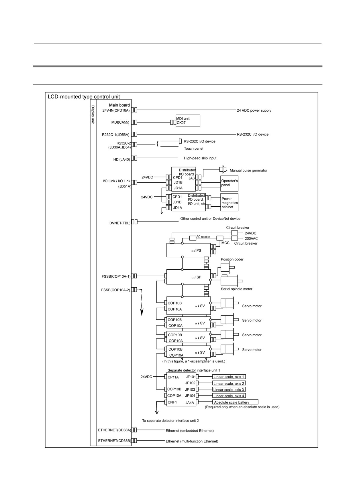
TOTAL CONNECTION DIAGRAMS
2.3.1
Control Unit Connection Diagram
- 163 -
2.CONTROL UNIT HARDWARE
B-64485EN/01
NOTE
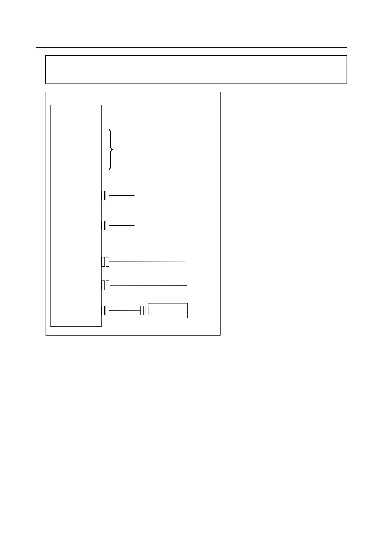
See the following descriptions for connections unique to control units
incorporating personal computer function with Windows Windows® CE.
LCD-mounted type control unit (personal computer function with Windows® CE)
LCD-mounted type
control unit
24V-IN(CPD16A)
I/O LINK(JD51A)
See the descriptions on the previous
HDI(JA40)
page for the functions of the
MDI(CA55)
connectors listed on the left and how
to attach them.
FSSB(COP10A-1)
FSSB(COP10A-2)
R232-1(JD56A)
RS-232C I/O device
RS-232C I/O device
R232-2/USB(JD54)
Personal computer
{
USB keyboard
Ethernet (embedded Ethernet)
ETHERNET (CD38S)
Ethernet (multi-function Ethernet)
ETHERNET (CD38B)
BUZZER for T.P.
Buzzer
(CA76)
- 164 -
B-64485EN/01
2.CONTROL UNIT HARDWARE
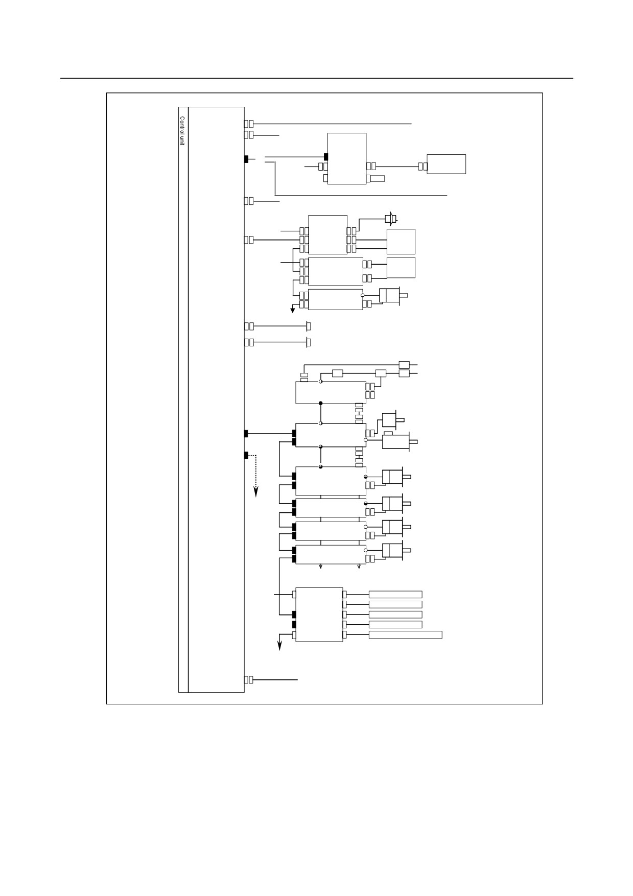
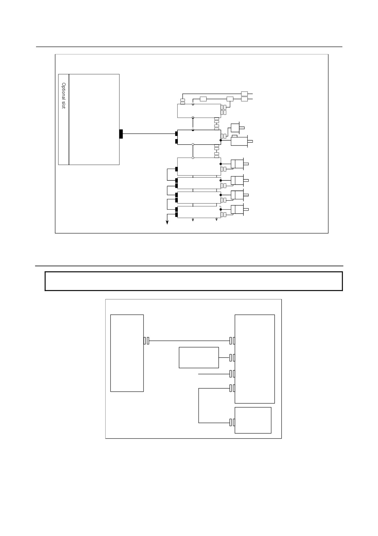
Stand-alone type control unit
Main board
24V-IN(CPD19A)
24 VDC power supply
24V-OUT(CPD19B)
To I/O device
Display unit
COP21A,B,M
DISPLAY(COP21A)
{
MDI unit
24VDC
CP1A
CA55
CK27
CP1B
Memory card
(Touch panel)
PANEL i or personal computer
HDI(JA40)
High-peed skip input
Distributed
Manual pulse generator
I/O board
VDC24
CPD1 JA3
Operator's
I/O Link i I/O Link
JD1B
panel
(JD51A)
JD1A
VDC24
CPD1
Distributed
Power
I/O board,
magnetics
JD1B
I/O unit, etc.
cabinet
JD1A
JD1B
βamplifier
with I/O Link
Servo motor
JD1A
R232C-1(JD56A)
RS-232C I/O device
R232C-2(JD36A)
RS-232C I/O device
Circuit breaker
24VDC
AC reactor
200VAC
MCC Circuit breaker
αi PS
Position coder
FSSB(COP10A-1)
αi SP
Serial spindle motor
FSSB(COP10A-2)
COP10B
αi SV
Servo motor
COP10A
COP10B
Servo motor
αi SV
COP10A
COP10B
Servo motor
αi SV
COP10A
COP10B
Servo motor
αi SV
COP10A
(In this figure, a 1-axis amplifier is used.)
Separate detector interface unit 1
DC24V
CP11A
JF101
Linear scale, axis 1
JF102
Linear scale, axis 2
COP10B
JF103
Linear scale, axis 3
COP10A JF104
Linear scale, axis 4
CNF1
JA4A
Battery for absolute scale
(Required only when an absolute scale is used)
To separate detector interface unit 2
ETHERNET(CD38A)
Ethernet (embedded Ethernet)
- 165 -
2.CONTROL UNIT HARDWARE
B-64485EN/01
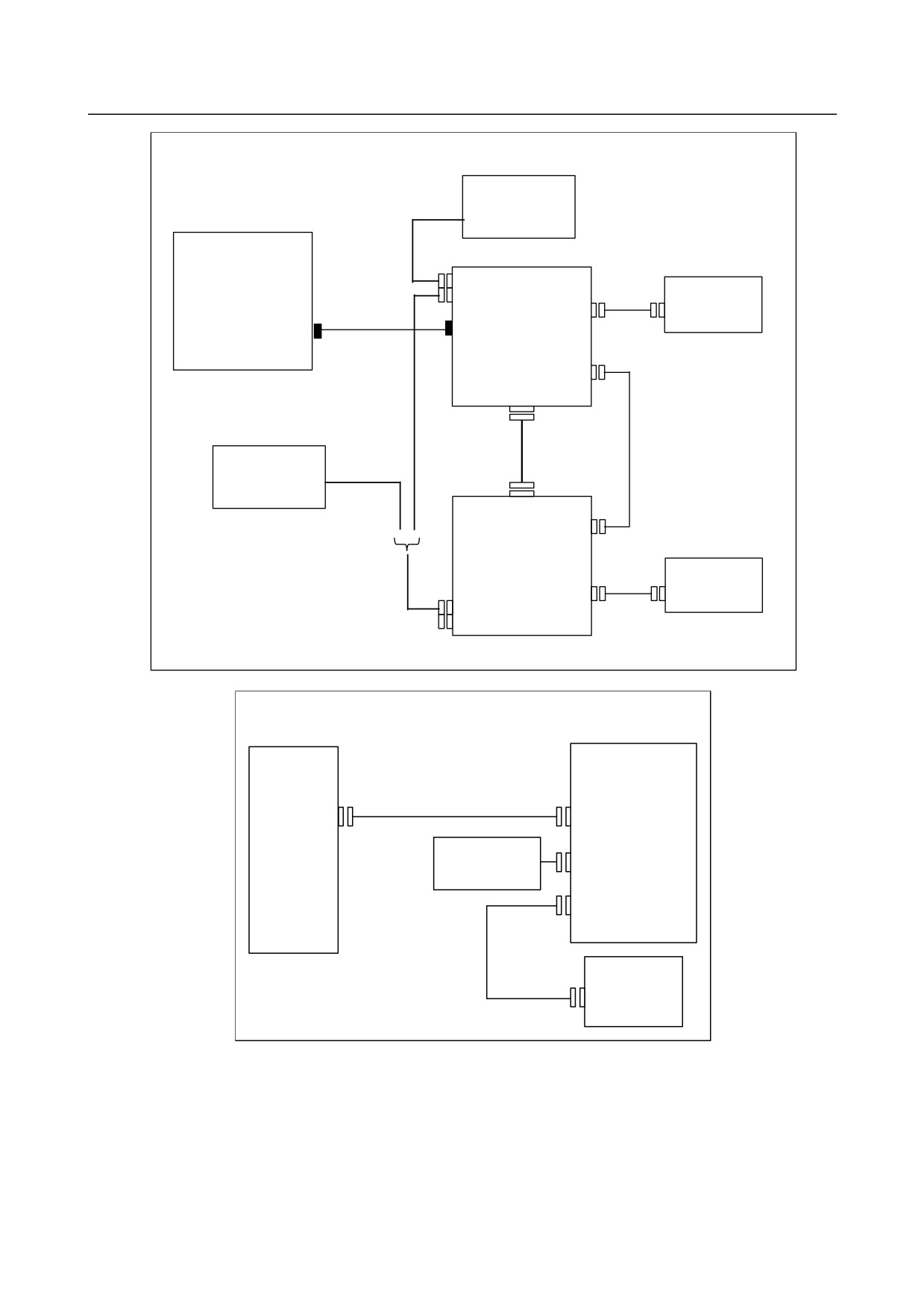
When optional boards are provided
Fast Ethernet board
Compact flash card
Use a compact flash card purchased from FANUC
ETHERNET(CD38R)
Ethernet or FL-net ,and so on
HSSB interface board
HSSB(COP21A)
PANEL i
or Personal Computer
PROFIBUS-DP
master board
PROFI(CN1)
Other control unit
or PROFIBUS device
PROFIBUS-DP
slave board
PROFI(CN2)
Other control unit
or PROFIBUS device
DeviceNet
master board
DVNET(TNB)
Other control unit
or DeviceNet device
DeviceNet
slave board
DVNET(TNB)
Other control unit
or DeviceNet device
CC-Link remote
device station board
CCLNK(CT1)
CC-Link device
- 166 -
B-64485EN/01
2.CONTROL UNIT HARDWARE
When one or more option boards are present
Additional axis
board
Circuit breaker
24VDC
AC reactor
200VAC
MCC Circuit breaker
αi PS
Position coder
αi SP
FSSB(COP10A-3)
Serial spindle motor
COP10B
αi SV
Servo motor
COP10A
Servo motor
COP10B
αi SV
COP10A
Servo motor
COP10B
αi SV
COP10A
Servo motor
COP10B
αi SV
COP10A
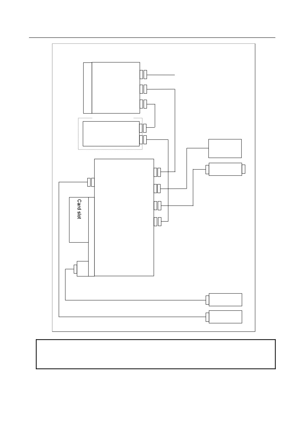
2.3.2
Connection Diagram of a Display Unit for the Stand-Alone
Type Control Unit
NOTE
See the connection diagram that matches the display unit you are using.
Display unit (10.4” LCD unit A)
Stand-alone
Display unit
type control
unit
Optical fiber cable
COP21B
COP21A
External power
supply
CP1A
24VDC±10%
CP1B
CA55
MDI cable
MDI unit
CK27
- 167 -
2.CONTROL UNIT HARDWARE
B-64485EN/01
With Two Display Units
External
power supply
24VDC±10%
Stand-alone
type
1st display unit
control unit
CP1A
MDI unit
CP1B
CA55
CK27
MDI
COP21B
cable
COP21A
Optical fiber cable
JA73
24-V power
cable
CA103
Video cable
between units
External
MDI cable
power supply
between units
24VDC±10%
CA103
JA73
MDI unit
CA55
CK27
CP1A
MDI
cable
CP1B
2nd display unit
Display unit (10.4” LCD unit B and 15” LCD unit)
Stand-alone
Display unit
type control
unit
Optical fiber cable
COP21A
COP21M
External power
supply
CPD18
24VDC±10%
CA55
MDI cable
MDI unit
CK27
- 168 -
B-64485EN/01
2.CONTROL UNIT HARDWARE
With the Display Unit for Automotive
Control unit
24V-IN(CPD19A)
DISPLAY(COP21A)
I/O Link (JD51A)
I/O Link device
I/O Link (JD1B)
I/O Link (JD1A)
External
power supply
24VDC±10%
Display unit for automotive
I/O Link device
HSSB (COP21M)
+24V (CPD18)
(Note 1)
I/OLink(JD1A)
(Note 1)
I/OLink(JD1B)
USB mouse
USB keyboard
USB mouse
USB keyboard
NOTE
1 The I/O Link interface is optional.
2 On the display unit for automobile manufacturers, the MDI unit is built onto the
front panel.
- 169 -
2.CONTROL UNIT HARDWARE
B-64485EN/01
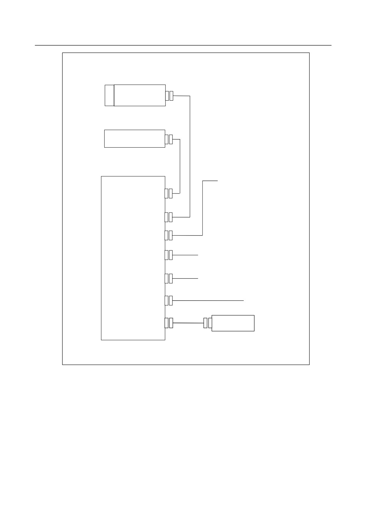
Stand-alone type control unit (personal computer function with Windows® CE)
Control unit
Main board
HSSB(COP21A)
MDI unit
(CK27)
Display unit
Power supply (+24VDC)
MDI(CA55)
HSSB(COP21M)
24V-IN(CPD18)
RS-232C I/O device
Personal computer
R232-2/USB(JD54)
USB keyboard
{
USB printer
R232-1(JD36)
RS-232C I/O device
Ethernet (embedded Ethernet)
ETHERNET(CD38S)
BUZZER for T.P.
Buzzer
(CA76)
- 170 -
B-64485EN/01
2.CONTROL UNIT HARDWARE
2.4
HARDWARE OF LCD-MOUNTED TYPE CONTROL UNIT
2.4.1
LCD-mounted Type Control Unit (8.4” LCD Unit and 10.4”
LCD Unit A)
-
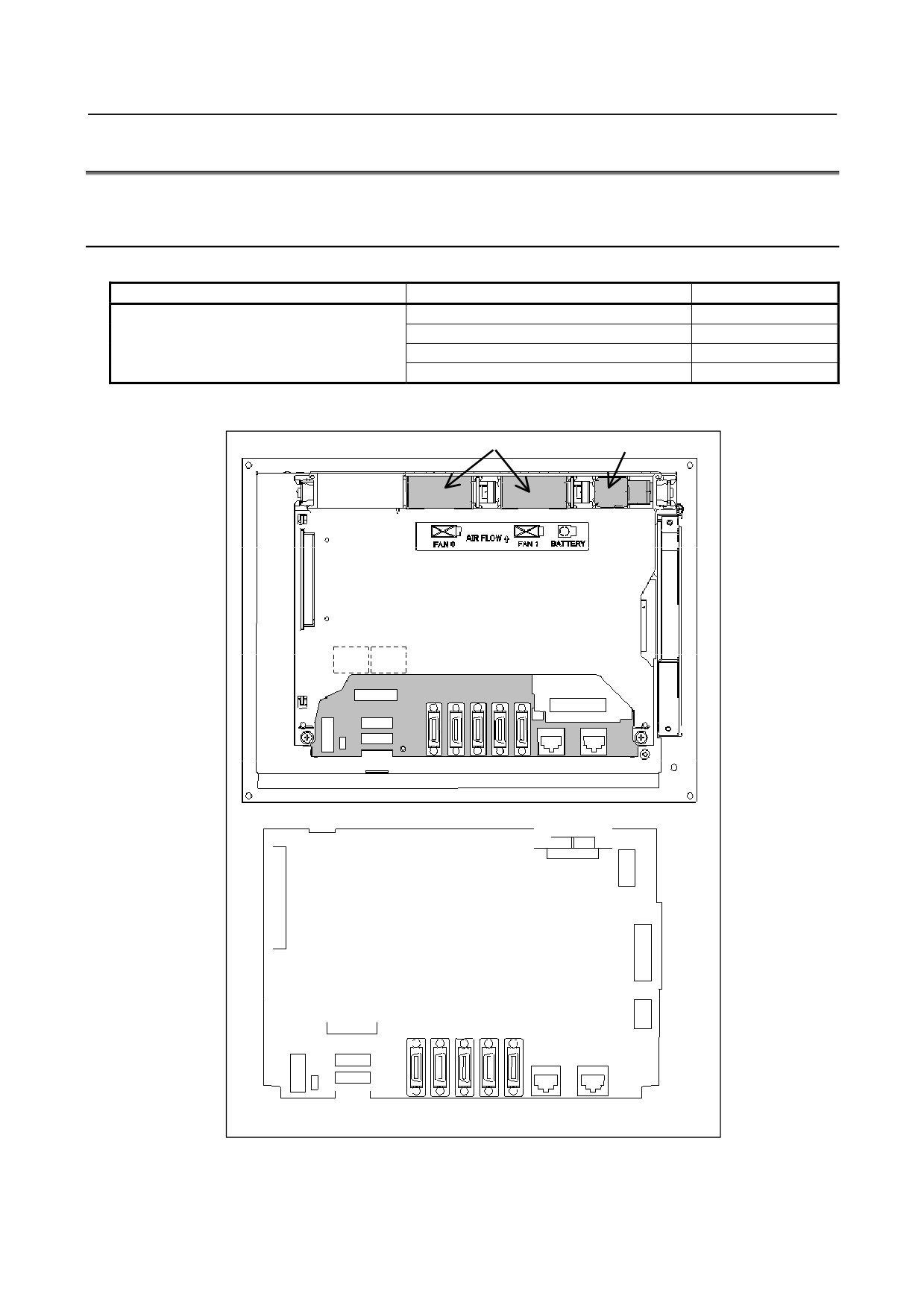
Main board specification
Name
Specification
Remark
Main board
A20B-8200-0720
A20B-8200-0721
A20B-8200-0723
A20B-8200-0724
-
Connector mounting location
Fan motor
Battery
Rear view
COP10A-1 COP10A-2
(COP10A is a connector installed on the servo card.)
TBL
CA55
JD56A
JA40
CDP16A
CK20A
CK21A
Fuse
JD36A JD51A CD38A
CD38B
CA132
JGM
CA135
Main board
CA88A
CD46A
CA55
JD56A
JA40
CPD16A
CK20A
CK21A
Fuse
JD36A JD51A
CD38A
CD38B
- 171 -
2.CONTROL UNIT HARDWARE
B-64485EN/01
Connector number
Application
COP10A-1, COP10A-2
For FSSB interface
CA55
For MDI
JD56A
For I/O device interface (RS-232C)
JD36A
For I/O device interface (RS-232C)
JA40
For high-speed skip
JD51A
For I/O Link i and I/O Link
CPD16A
For power supply
JGM
For back panel
CA135
For video signal interface
CA88A
For memory card interface
CD46A
For USB port
CK20A
For horizontal soft key
CK21A
For vertical soft key
CA132
For inverter board
CD38A
For Ethernet (Embedded Ethernet)
CD38B
For Ethernet (Multi-function Ethernet)
TBL
For DeviceNet interface
-
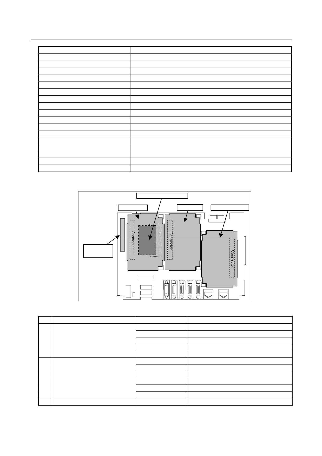
Locations of printed circuit boards
(4) FROM/SRAM module
(1) Servo card
(2) CPU card
(3) DeviceNet card
(5) Back panel
(with a power
l
)
No.
Name
Specification
Remark
(1)
Servo card
A20B-3300-0660
A20B-3300-0661
A20B-3300-0662
A20B-3300-0663
A20B-3300-0664
(2)
CPU card
A20B-3300-0650
A20B-3300-0651
A20B-3300-0652
A20B-3300-0653
A20B-3300-0654
A20B-3300-0655
(3)
DeviceNet card
A20B-3200-0020
- 172 -
B-64485EN/01
2.CONTROL UNIT HARDWARE
No.
Name
Specification
Remark
(4)
FROM/SRAM module
A20B-3900-0250
The FROM stores various control software
A20B-3900-0251
programs, user software programs, and so
A20B-3900-0252
forth. The SRAM is a battery-backed memory
module.
(5)
Back panel (with power supply)
A20B-8200-0650
A20B-8200-0670
A20B-8200-0680
-
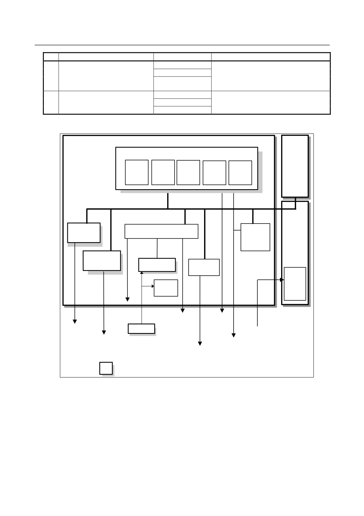
Block diagram
Optional
Main board
board
CPU card
CPU
DRAM
BOOT
Ethernet
I/O Link
software
control
control
Servo card
Peripheral control
I/O Link i,
I/O Link
control
Back panel
DeviceNet card
FROM/SRAM
Communication
module
function
Power
supply
Calendar
function
LCD
unit
MDI
Ethernet
RS-232C
(embedded
Memory card
Ethernet)
Battery
USB
FSSB
24VDC
High-speed skip
DeviceNet
I/O Link i
Ethernet (multi-function
I/O Link
Ethernet)
: Detachable card or module
- 173 -
2.CONTROL UNIT HARDWARE
B-64485EN/01
-
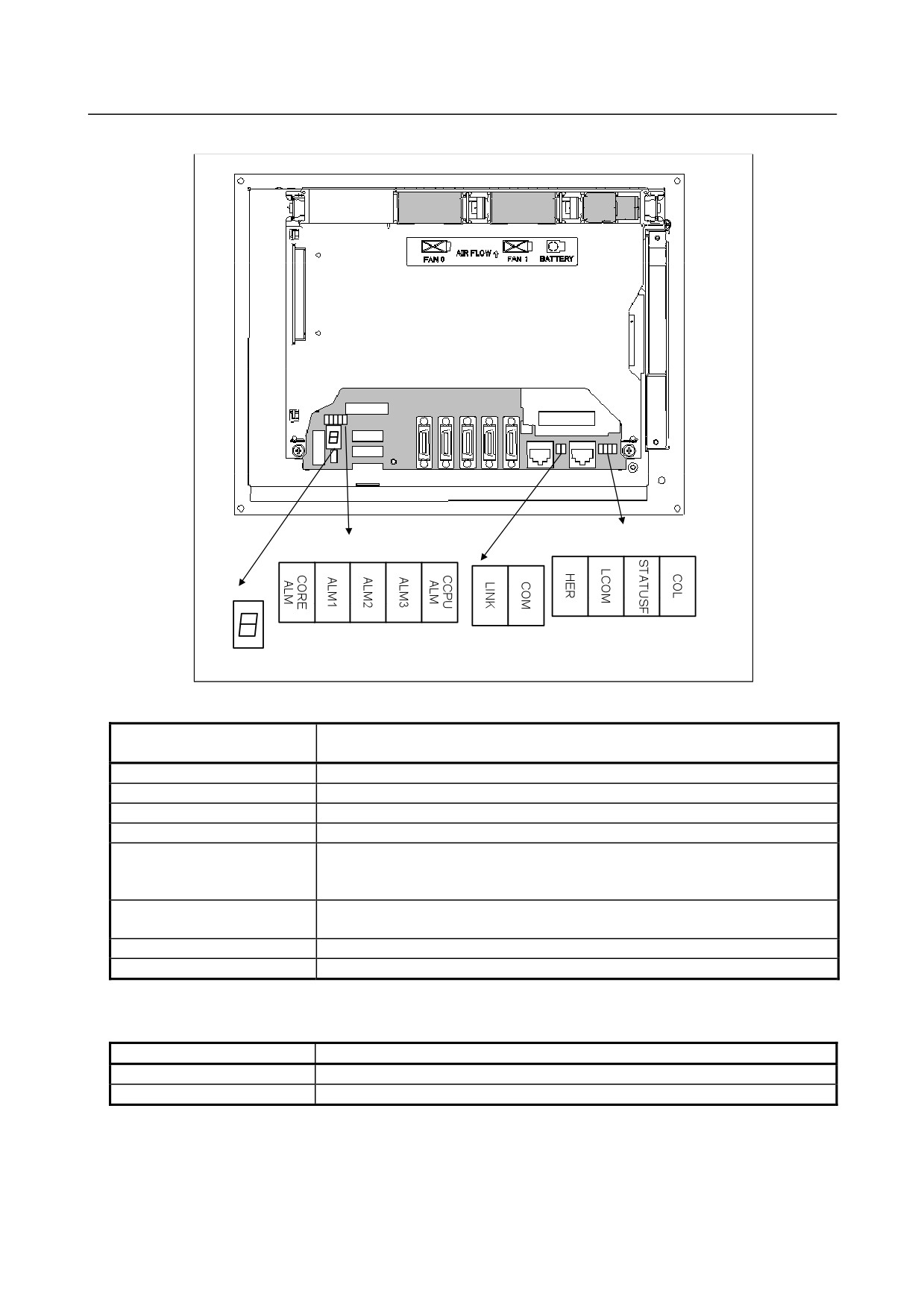
LED display
Rear view
(3) Ethernet (multi-function Ethernet)
(1) Alarm LED
Status LED
(green) (yellow)
(2) Ethernet (embedded Ethernet)
(4) 7-segment LED
Status LED
(1) Alarm LED (red) indication
CORE ALM CCPU
Meaning
ALM
1
2
3 ALM
◇
□
■ □
◇
Low battery voltage. The battery may be is running out.
◇
■
■ □
◇
Software detected an error and stopped the system.
◇
□
□ ■
◇
Hardware detected a failure in the system.
◇
■
□ ■
◇
An alarm was issued with the servo card on the main board.
◇
□
■ ■
◇
An error was detected in the data of the SRAM on the FROM/SRAM module.
The FROM/SRAM module may be faulty, the battery voltage may have dropped, or
the main board may be faulty.
◇
■ ■ ■
◇
Abnormal power supply operation. The cause may be noise or the back panel (with
power supply) failure.
◇
◇ ◇ ◇
■
The CPU card may be faulty.
■
◇ ◇ ◇
◇
Lights if there is an abnormal condition in the power supply on the main board.
■: On
□: Off
◇: Don’t care
(2) Ethernet (Embedded Ethernet) statusLED
LED
Meaning
LINK (green)
Turned on when a connection is made with the hub correctly.
COM (yellow)
Turned on when data is transferred.
- 174 -
B-64485EN/01
2.CONTROL UNIT HARDWARE
(3) Ethernet (Multi-function Ethernet) statusLED
In the following explanations, the LED lighting states are expressed as follows:
□: Off
■: On
☆: Blinking
-
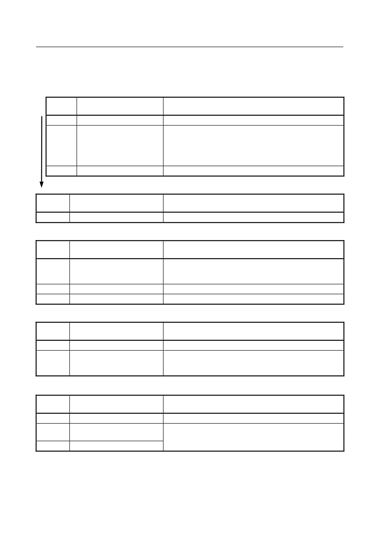
LED display transition for STATUSF (power on state)
LED
Status
Meaning
display
□
Power-off
■
Immediately after power-on
Initial state entered immediately after power-on.
If LED is stopped in this condition, the cause is one of the following:
→ The CNC communication software may not be running normally.
Check whether the communication software is installed properly.
→ The main board may be faulty. Replace the main board.
☆
Start completion
The Multi-function Ethernet has started normally.
-
LED display for STATUSF (during normal operation)
LED
Status
Meaning
display
☆
Normal status
The Multi-function Ethernet is operating normally.
-
LED display for LCOM
LED
Status
Meaning
display
□
Not connected to hub
The board is not connected to the hub properly.
The LED stays off also when the power to the hub is off.
Check whether the board is connected to the hub properly.
■
Connected to hub
The board is connected to the hub.
☆
Transmission/reception in progress
Data is being transmitted or received.
-
LED display for COL
LED
Status
Meaning
display
□
Normal status
The Multi-function Ethernet is operating normally.
■
Collision occurs.
The LED is on or blinks at short intervals when the Ethernet
☆
(Data collision occurs.)
communication traffic (communication amount) is high or ambient
noise is high.
-
LED display for HER
LED
Status
Meaning
display
□
Normal status
The Multi-function Ethernet is operating normally.
■
Error detected in the Ethernet
The cause may be the faulty main board or a malfunction due to
circuit on the main board
noise.
☆
Error detected in the software
(4)
7-segment LED
See Appendix E, “LED Display”.
- 175 -
2.CONTROL UNIT HARDWARE
B-64485EN/01
-
Inverter board specification
Name
Specification
Remark
Inverter board
For 8.4-inch LCD
A20B-8200-0663
For 10.4-inch LCD
A20B-8200-0662
-
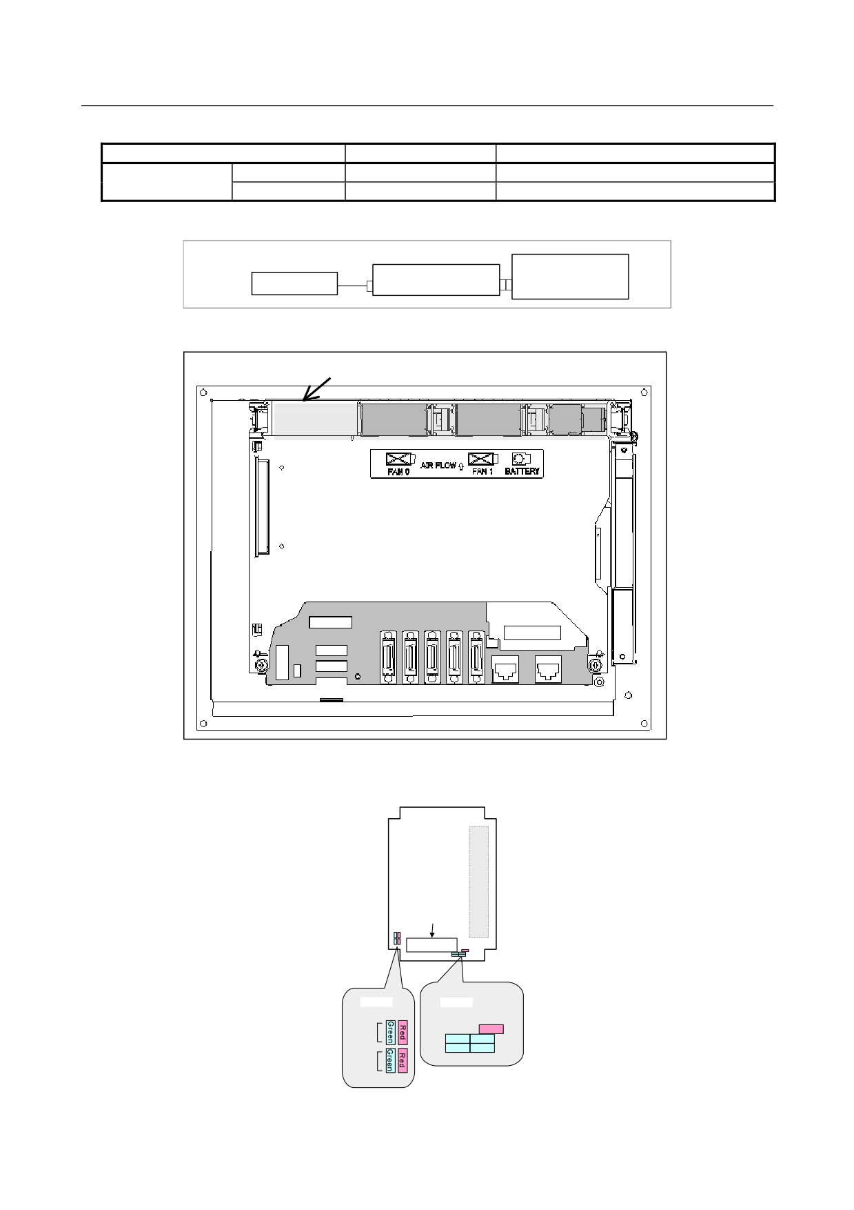
Configuration of the inverter
Main board
Inverter board
LCD unit
CPA11
CA132
CA132
-
Location of the inverter board
Inverter board
Rear view
DeviceNet card
Connector and LED mounting location
Outside line
connector
TBL
LED
LED
LEDWD
Red
MS
LED0Green
Green
LED2
LED1Green
Green
LED3
NS
- 176 -
B-64485EN/01
2.CONTROL UNIT HARDWARE
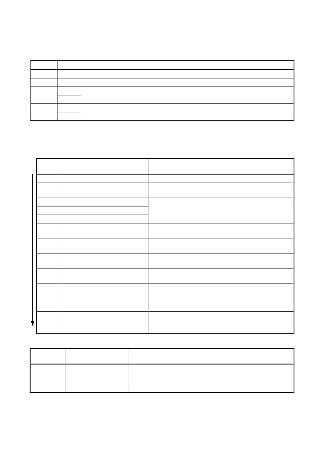
This card provides four green LEDs (LED0 to LED3) and one red LED (LEDWD) for status indication.
In addition, it provides two types of LED units (MS and NS) that have one red LED and one green LED.
Name
Color
Meaning
LED0 to 3
Green
Indicates the activation state of the DeviceNet application software.
LEDWD
Red
Indicates an error on the DeviceNet card.
Green
MS
Indicates the module status, which is the status of the local node.
Red
Green
NS
Indicates the network status, which is the status of the entire network including the local node.
Red
In the following explanations, the LED lighting states are expressed as follows:
□: Off
■: On
☆: Blinking
◇: Don’t care
LED display transition for LED0, LED1, LED2, and LED3 (during power-on)
LED
Status after power-on
Action when stopped after power-on
3 2 1 0
□□□□
Power-off
■■■■
After power-on, the DeviceNet
The DeviceNet application software is not running normally. Check
application software does not start.
whether the software is installed properly.
□□□□
Initializing the firmware.
Replace the DeviceNet card.
□□□■
Checking memory.
□□■□
Recognizing the firmware.
□□■■
Reading DeviceNet parameters.
Confirm that DeviceNet master function (software option) has
been purchased.
□■□□
Verifying that DeviceNet parameter
Set DeviceNet parameter “NETWORK” to “ONLINE.”
“NETWORK” is set to “ONLINE.”
□■□■
Setting the bus parameter in DeviceNet
Replace the DeviceNet card.
parameters.
□■■□
Setting the slave parameter in
Set the slave parameter in DeviceNet parameters correctly. If
DeviceNet parameters.
there is no problem with the setting, replace the DeviceNet card.
□■■■
Checking duplicate MAC IDs.
Check duplication with the MAC ID of a slave device.
Check if cables are connected correctly.
Check if power for communication is correctly supplied.
Check if slave devices are turned on.
■□□□
The DeviceNet application software has
been initialized and I/O communication
starts.
LED display for LED1, LED2, LED3, and LED4 (when abnormality occurs)
LED
Status
Meaning
3 2 1 0
□□□□
Card failure
The DeviceNet card failed.
↑↓
Replace the DeviceNet card.
■■■■
(Repetition)
- 177 -
2.CONTROL UNIT HARDWARE
B-64485EN/01
LED display for LEDWD
LED display
Status
Meaning
■
Card failure
The DeviceNet card failed.
Replace the DeviceNet card.
LED display of MS and NS (during normal operation)
LED display
Status
Meaning
MS □
Immediately after power-on
The MPU is being reset.
NS □
MS ☆ green
Initializing
The firmware is making a initialization.
NS □
MS ■ green
Checking duplication of
The firmware is checking duplicated MAC IDs.
NS □
MAC IDs
MS ■ green
I/O communication stopped
The firmware is stopping I/O communication.
NS ☆ green
MS ■ green
I/O communication in
The firmware is successfully performing I/O communication.
NS ■ green
advance
LED display of MS and NS (during occurrence of an error)
LED
Status
Error and action
display
MS ☆ red
Card failure
A MAC ID or communication rate setting error occurred or the DeviceNet
NS ◇
card failed.
When the setting is correct, replace the card.
MS ■ red
Card failure
The DeviceNet card failed.
NS □
Replace the card.
MS ◇
Duplicate MAC IDs
MAC IDs are duplicate.
NS ■ red
Verify the following:
→ MAC IDs are not duplicate by check the MAC IDs of all nodes.
Busoff detection
Communication stopped because a communication error occurred
frequently.
Verify the following:
→ The communication rates of all nodes are set to the same value.
→ The cable length is appropriate.
→ The cable is not loose or broken.
→ A terminal is placed on only both ends of the main line.
→ There is not much noise.
MS ◇
Network power failure
Power for communication is not supplied.
NS □
Verify the following:
→ Power for communication is properly supplied.
Transmission error
Transmission is not completed successfully.
Verify the following:
→ All slaves are turned on.
→ There is no other master on the network.
→ The communication rates of all nodes are set to the same value.
→ The cable length is appropriate.
→ The cable is not loose or broken.
→ A terminal is placed on only both ends of the main line.
→ There is not much noise.
- 178 -
B-64485EN/01
2.CONTROL UNIT HARDWARE
LED
Status
Error and action
display
MS ◇
Slave not present
No slaves are present.
NS ☆ red
Verify the following:
→ The slave is turned on.
→ The communication rates of all nodes are set to the same value.
→ The cable length is appropriate.
→ The cable is not loose or broken.
→ A terminal is placed on only both ends of the main line.
→ There is not much noise.
Slave I/O size mismatch
The slave I/O size setting does not match the setting of the actual slave.
Verify the following:
→ The slave I/O size setting matches the setting of the actual slave.
I/O communication error
I/O communication timed out.
Verify the following:
→ The communication rates of all nodes are set to the same value.
→ The cable length is appropriate.
→ The cable is not loose or broken.
→ A terminal is placed on only both ends of the main line.
→ There is not much noise.
- 179 -
2.CONTROL UNIT HARDWARE
B-64485EN/01
2.4.2
LCD-mounted Type Control Unit (10.4” LCD Unit B and 15”
LCD Unit)
Main board specification
Name
Specification
Remark
Main board
For 10.4” LCD
A20B-8200-0708
A20B-8200-0709
A20B-8200-0718
A20B-8200-0719
For 15” LCD
A20B-8200-0702
A20B-8200-0706
A20B-8200-0712
A20B-8200-0716
-
Connector mounting location
Fan motor
Battery
(COP10A is a connector installed on the servo card.)
COP10A-1
CA139
Rear view
COP10A-2
JD56A
JD54
JA40
JD51A
CA134
CA55
CK20A
Fuse
CPD16A
CD38S CD38B
CK21A
CA132
CA135
JGM
CA133
CA139
Main board
CA88A
CA134
JD56A JA40
CD46L
Fuse
CA55
CPD16A
CK20A
CK21A
JD54
JD51A
CD38S
CD38B
Connector number
Application
COP10A-1, COP10A-2
For FSSB interface
CA55
For MDI
- 180 -
B-64485EN/01
2.CONTROL UNIT HARDWARE
Connector number
Application
JD56A
For I/O device interface (RS-232C)
JD54
For I/O device interface (RS-232C)
JA40
For high-speed skip
JD51A
For I/O Link i and I/O Link
CPD16A
For power supply
JGM
For back panel
CA133
For video signal interface (for 10.4”LCD)
CA135
For video signal interface (for 15”LCD)
CA88A
For memory card interface
CD46L
For USB port
CK20A
For horizontal soft key
CK21A
For vertical soft key
CA132
For inverter board (for 10.4”LCD)
For fan adapter board (for 15”LCD)
CD38S
Ethernet (Embedded Ethernet)
CD38B
Ethernet (Multi-function Ethernet)
CA139
㪝㫆㫉㩷㫋㫆㫌㪺㪿㩷㫇㪸㫅㪼㫃㩷㫀㫅㫋㪼㫉㪽㪸㪺㪼㩷
CA134
㪝㫆㫉㩷㫀㫅㫍㪼㫉㫋㪼㫉㩷㪹㫆㪸㫉㪻 (for 15”LCD)㩷
-
Card and back panel mounting location
Connector
Connector
(1) Servo card
(2) CPU card
(3) Back panel
(with power
(4) GU card
supply)
Connector
No.
Name
Specification
Remark
(1)
Servo card
See Subsection 2.4.1, “LCD-mounted
(2)
CPU card
Type Control Unit (8.4” LCD Unit and
10.4” LCD Unit A)”.
(3)
Back panel (with power
supply)
(4)
GUI card
A20B-3300-0670
- 181 -
2.CONTROL UNIT HARDWARE
B-64485EN/01
-
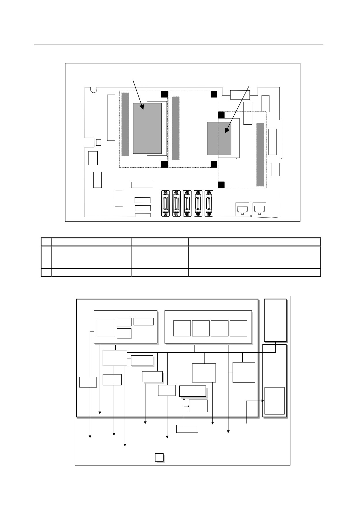
FROM/SRAM module and compact flash card mounting location
FROM/SRAM
Compact flash card
module
Connector
Connector
Connector
A compact flash card is mounted on the main board.
No.
Name
Specification
Remark
(1)
FROM/SRAM module
A20B-3900-0260
The FROM stores various control software programs,
user software programs, and so forth.
The SRAM is a battery-backed memory module.
(2)
Compact flash card
A02B-0323-C990#A
Including software
-
Block diagram
Optional
Main board
board
GUI card
CPU card
DRAM
Display control
CPU
CPU
DRAM
BOOT
I/O Link
software
control
BOOT
software
Peripheral
control 2
Compact
Flash card
Peripheral
I/O Link i,
control 1
I/O Link
Back panel
control
Servo card
USB
Ethernet
control
control
Communication
FROM/SRAM
function
Power
module
supply
Calendar
function
LCD unit
RS-232C
FSSB
Battery
MDI
24VDC
High-speed skip
I/O Link i
USB
I/O Link
Ethernet
Ethernet (Multi-function
(Embedded
Ethernet)
Ethernet)
Memory card
: Detachable card or module
- 182 -
B-64485EN/01
2.CONTROL UNIT HARDWARE
-
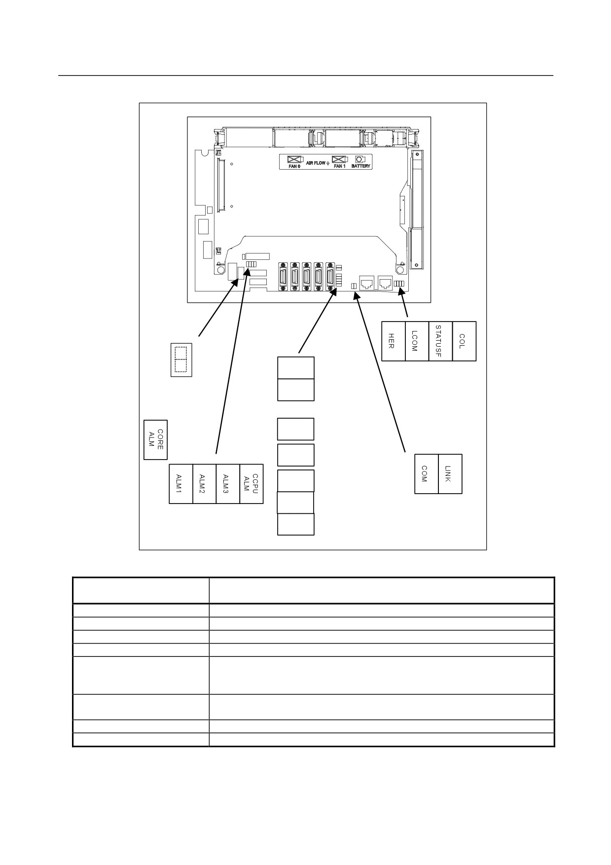
LED display
Rear view
DNV9
(red) (yellow) (green) (red)
(3)
(7) Ethernet
DNV8
(8) 7-segment LED
GUI status 2
(Multi-function
LED(green)
Ethernet) status LED
DNV5
(5) LEDP(green)
DNV4
(4) GUI alarm
LED(red)
DNV3
(2) GUI status 1
LED(green)
DNV2
(yellow) (green)
(1) Alarm LED(red)
(6) Ethernet (Embedded
DNV1
Ethernet) status LED
(1) Alarm LED (red LED)
CORE ALM CCPU
Meaning
ALM
1
2
3 ALM
◇
□
■ □
◇
Low battery voltage. The battery may be is running out.
◇
■
■ □
◇
Software detected an error and stopped the system.
◇
□
□ ■
◇
Hardware detected a failure in the system.
◇
■
□ ■
◇
An alarm was issued with the servo card on the main board.
◇
□
■ ■
◇
An error was detected in the data of the SRAM on the FROM/SRAM module.
The FROM/SRAM module may be faulty, the battery voltage may have dropped, or
the main board may be faulty.
◇
■ ■ ■
◇
Abnormal power supply operation. The cause may be noise or the back panel (with
power supply) failure.
◇
◇ ◇ ◇
■
The CPU card may be faulty.
■
◇ ◇ ◇
◇
Lights if there is an abnormal condition in the power supply on the main board.
■: On
□: Off
◇: Don’t care
- 183 -
2.CONTROL UNIT HARDWARE
B-64485EN/01
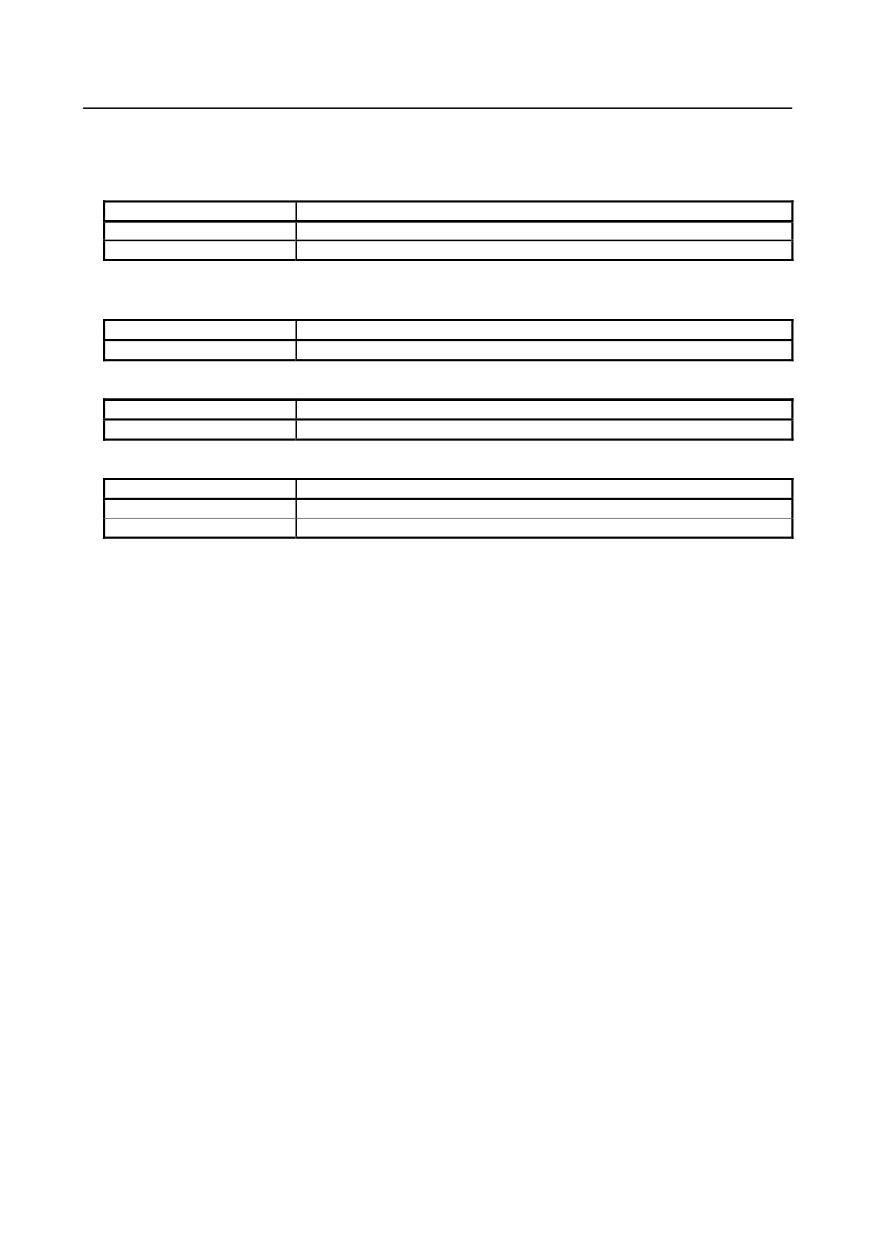
(2) GUI status 1 LED (green LED)
Reserved.
(3) GUI status 2 LED (green LED)
LED
Meaning
DNV8 (LED2)
Indicates the operation status of the screen display function.
DNV9 (LED1)
Indicates the operation status of the screen display function.
■: On
□: Off
(4) GUI alarm LED (red LED)
LED
Meaning
DNV4 (RAME)
Common RAM error. The main board may be faulty.
(5) LEDP (green LED)
LED
Meaning
DNV5 (LEDP)
Turned on when power is supplied to the GUI card.
(6) Ethernet (Embedded Ethernet) status LED
LED
Meaning
LINK (green)
Turned on when a connection is made with the hub correctly.
COM (yellow)
Turned on when data is transferred.
- 184 -
B-64485EN/01
2.CONTROL UNIT HARDWARE
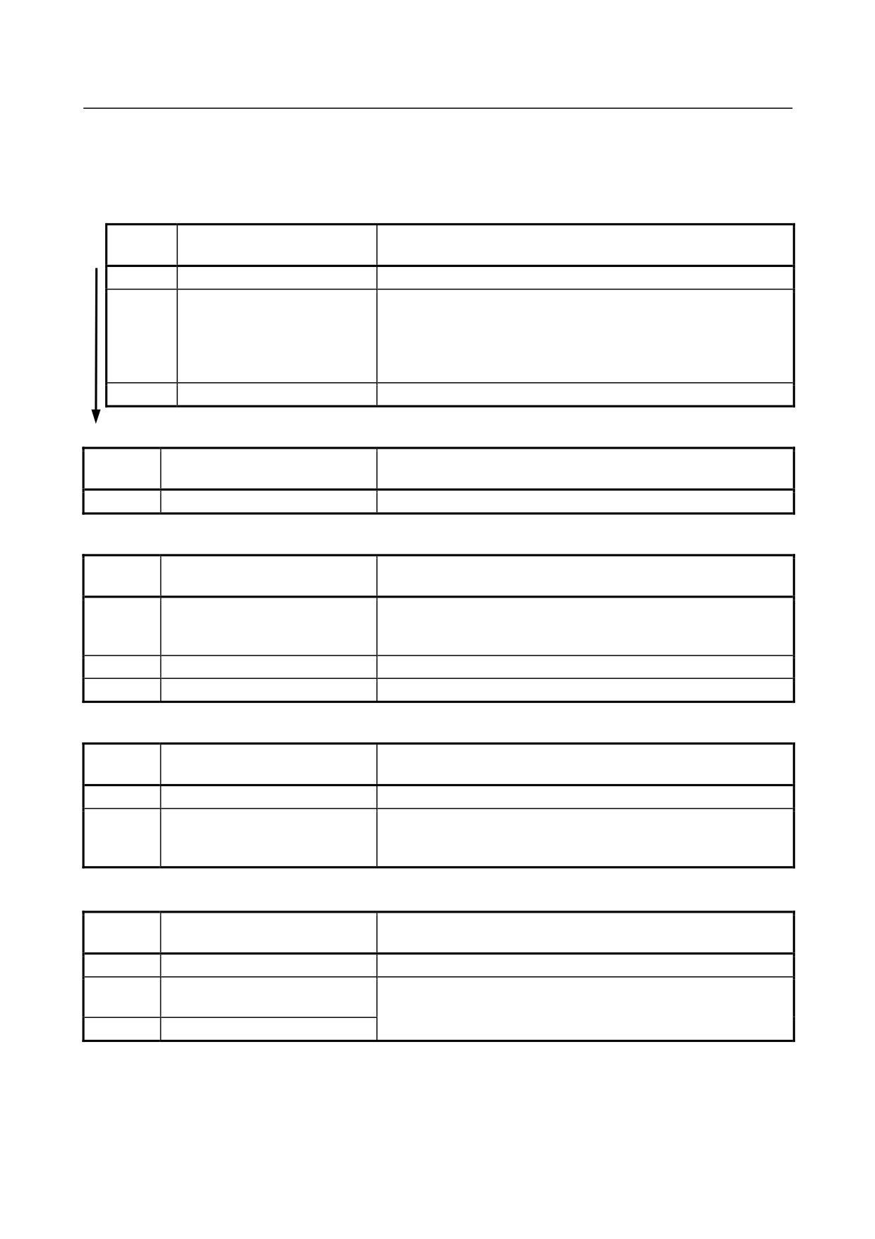
(7) Ethernet (Multi-function Ethernet) status LED
In the following explanations, the LED lighting states are expressed as follows:
□: Off
■: On
☆: Blinking
-
LED display transition for STATUSF (power on state)
LED
Status
Meaning
display
□
Power-off
■
Immediately after power-on
Initial state entered immediately after power-on.
If LED is stopped in this condition, the cause is one of the following:
→ The CNC communication software may not be running normally.
Check whether the communication software is installed properly.
→ The main board may be faulty. Replace the main board.
☆
Start completion
The Multi-function Ethernet has started normally.
-
LED display for STATUSF (during normal operation)
LED
Status
Meaning
display
☆
Normal status
The Multi-function Ethernet is operating normally.
-
LED display for LCOM
LED
Status
Meaning
display
□
Not connected to hub
The board is not connected to the hub properly.
The LED stays off also when the power to the hub is off.
Check whether the board is connected to the hub properly.
■
Connected to hub
The board is connected to the hub.
☆
Transmission/reception in progress
Data is being transmitted or received.
-
LED display for COL
LED
Status
Meaning
display
□
Normal status
The Multi-function Ethernet is operating normally.
■
Collision occurs.
The LED is on or blinks at short intervals when the Ethernet
☆
(Data collision occurs.)
communication traffic (communication amount) is high or ambient
noise is high.
-
LED display for HER
LED
Status
Meaning
display
□
Normal status
The Multi-function Ethernet is operating normally.
■
Error detected in the Ethernet
The cause may be the faulty main board or a malfunction due to
circuit on the main board
noise.
☆
Error detected in the software
(8)
7-segment LED
See Appendix E, “LED Display”.
- 185 -
2.CONTROL UNIT HARDWARE
B-64485EN/01
-
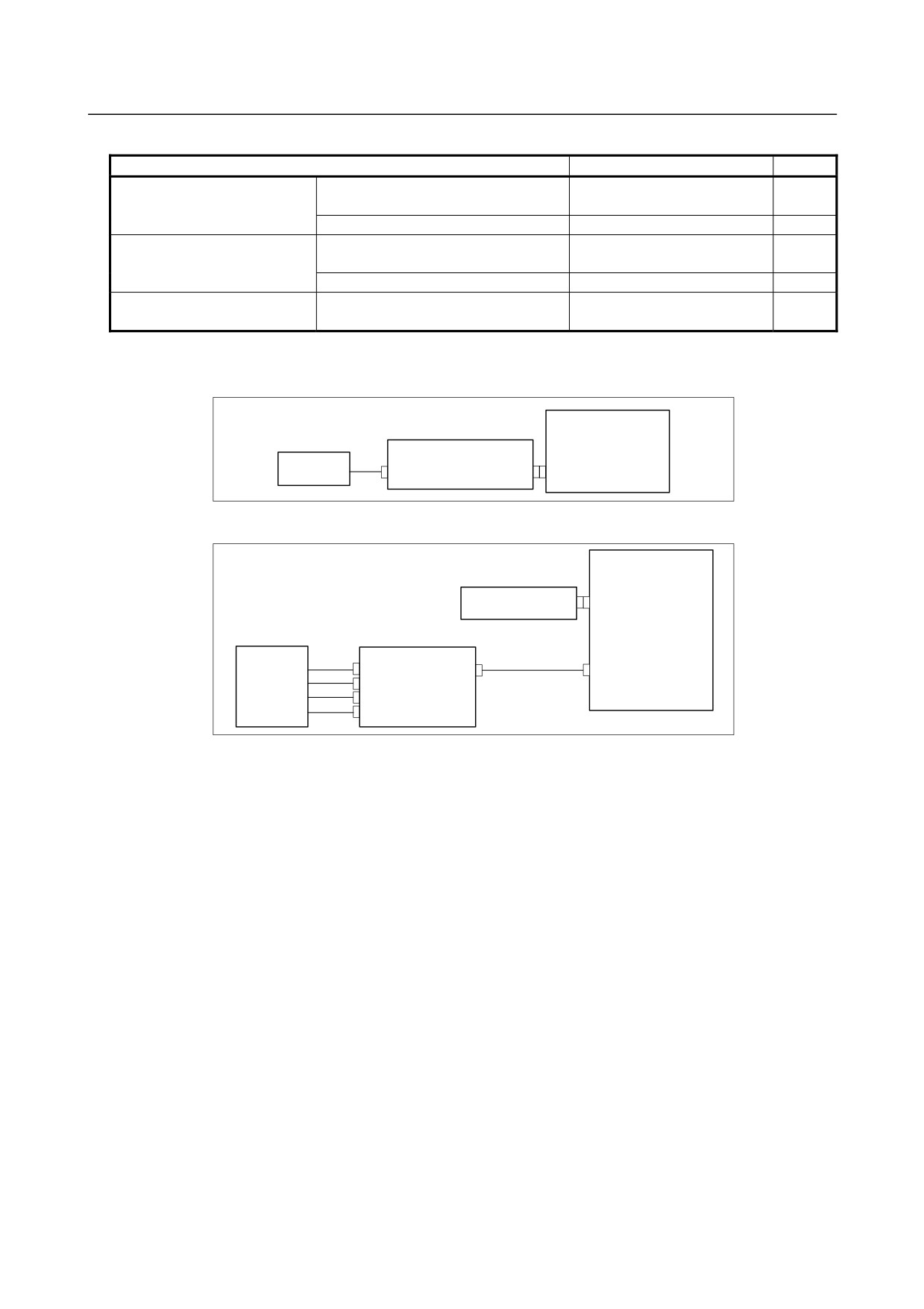
Inverter board and fan adapter board
Name
Specification
Remark
Inverter board
For 10.4” LCD (working also as fan
A20B-8200-0662
adapter board)
For 15” LCD
A14L-0168-0001
Fan adapter board
For 10.4” LCD (working also as fan
Works also as the inverter
adapter board)
board mentioned above.
For 15” LCD
A20B-8200-0669
Main board-to-inverter board
For 15” LCD
A660-4042-T076#L75R00
connection cable
Configuration of the inverter
(1) For control unit with 10.4” LCD
Main board
Inverter board
10.4”LCD unit
(Also functions as a fan adapter board.)
CA132
CP1
CN1
(2) For control unit with 15” LCD
Main board
Fan adapter boartd
CA132
CN1
15”LCD unit
Inverter board
CA134
CN02
CN01
Inverter connection cable
CN03
CN04
CN05
- 186 -
B-64485EN/01
2.CONTROL UNIT HARDWARE
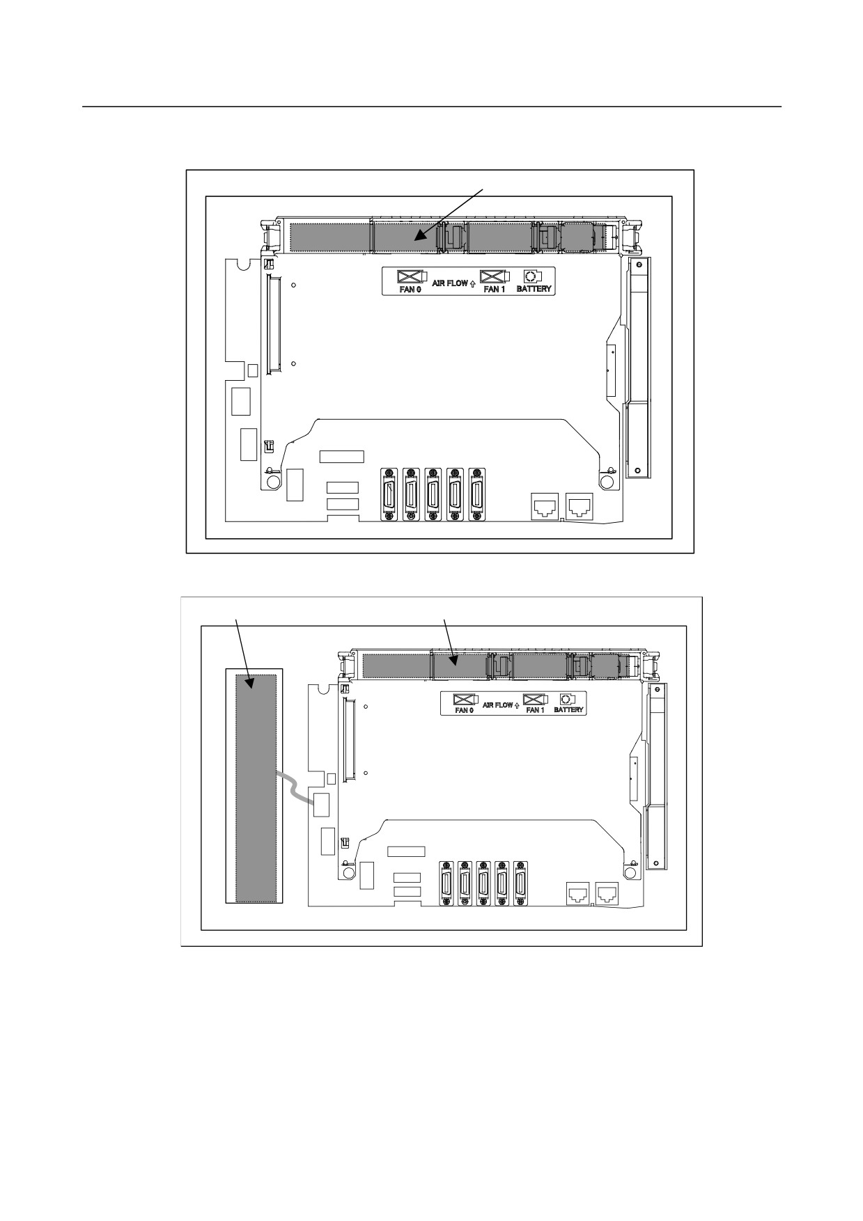
Locations of the inverter board and fan adapter board
(1) For control unit with 10.4” LCD
Inverter board
Rear view
(2) For control unit with 15” LCD
Fan adapter board
Inverter board
Rear view
- 187 -
2.CONTROL UNIT HARDWARE
B-64485EN/01
2.4.3
LCD-mounted Type Control Unit (with Personal Computer
Function with Windows®CE) Hardware
-
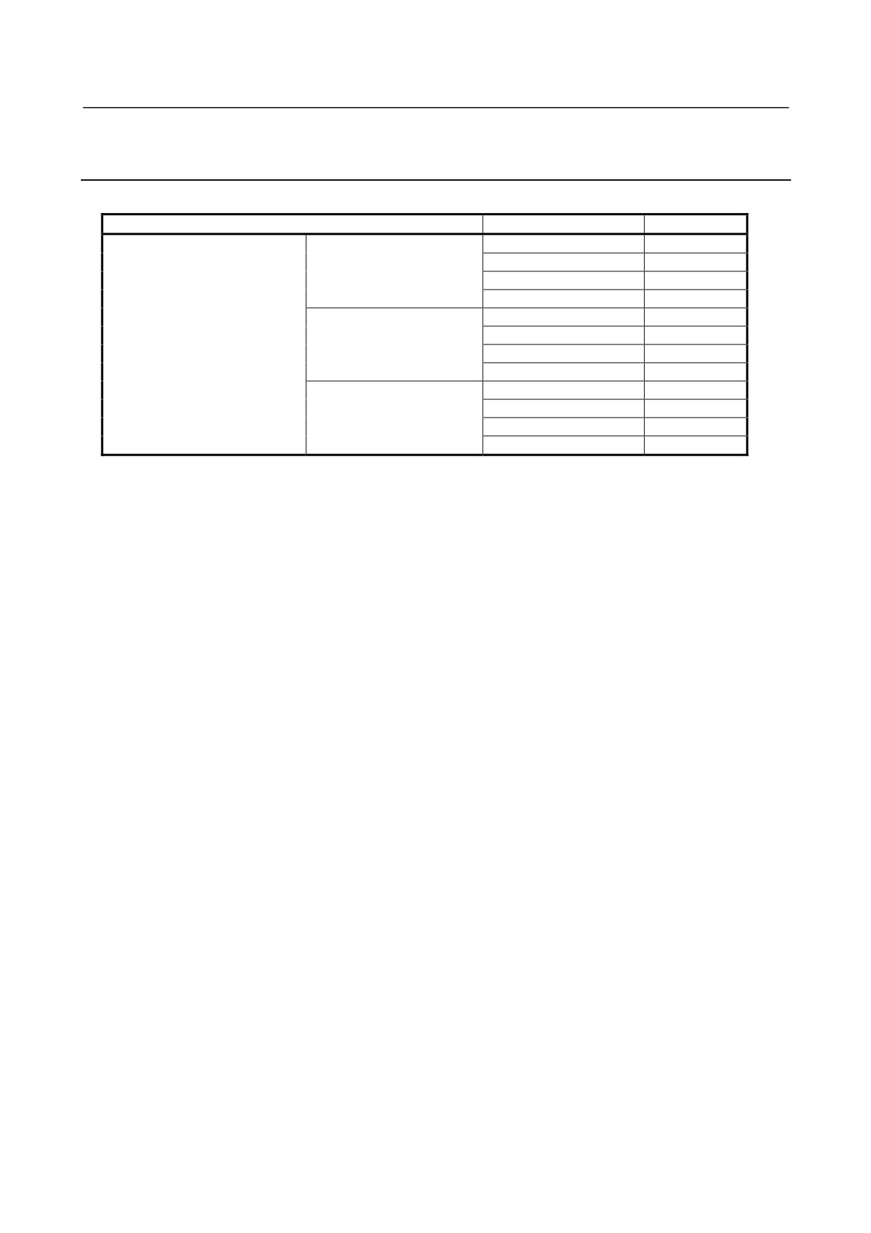
Main board specification
Name
Specification
Remark
Main board
For 10.4” LCD
A20B-8200-0700
A20B-8200-0704
A20B-8200-0710
A20B-8200-0714
For 12.1” LCD
A20B-8200-0703
A20B-8200-0707
A20B-8200-0713
A20B-8200-0717
For 15" LCD
A20B-8200-0701
A20B-8200-0705
A20B-8200-0711
A20B-8200-0715
- 188 -
B-64485EN/01
2.CONTROL UNIT HARDWARE
-
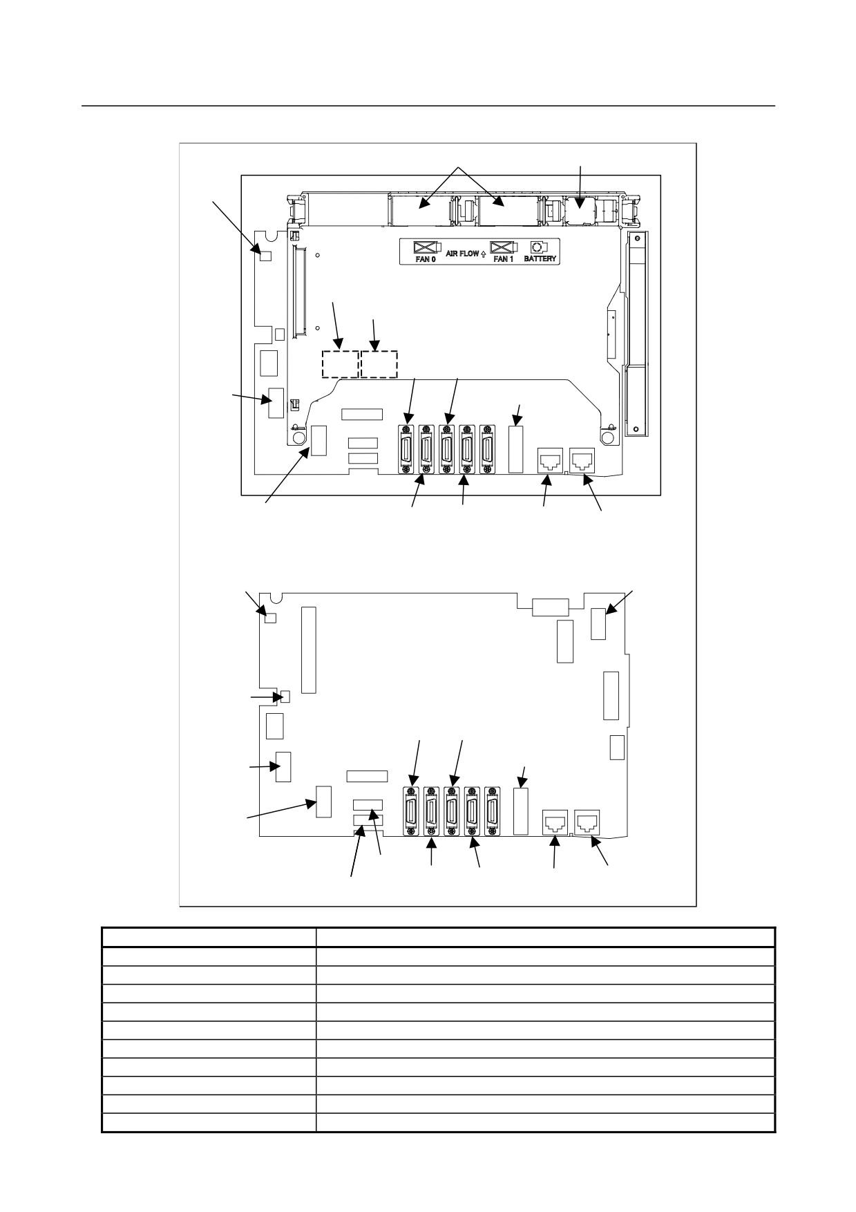
Connector mounting location
Fan motor
Battery
CA76
(COP10A is a connector installed on the servo card.)
COP10A-1
COP10A-2
Rear
JD56A JA40
Fuse
CA136
CA55
CPD16A
JD54 JD51A
CD38S
CD38B
CA76
CA135
CA132
JGM
CA133
CA139
Main board
CA88A
CA134
JD56A JA40
CD46L
CA136
CA55
Fuse
CPD16A
CK20A
JD54 JD51A
CD38S
CD38B
CK21A
Connector number
Application
COP10A-1, COP10A-2
For FSSB interface
CA55
For MDI
JD56A
For I/O device interface (RS-232C)
JD54
For I/O device interface (RS-232C) or USB device
JA40
For high-speed skip
JD51A
For I/O Link i and I/O Link
CPD16A
For power supply
JGM
For back panel
CA133
For video signal interface (for 10.4”/12.1”LCD)
CA135
For video signal interface (for 15”LCD)
- 189 -
2.CONTROL UNIT HARDWARE
B-64485EN/01
Connector number
Application
CA88A
For memory card interface
CD46L
For USB port
CK20A
For horizontal soft key
CK21A
For vertical soft key
CA132
For inverter board (for 10.4”LCD)
For fan adapter board (for 12.1”/15” LCD)
CD38S
For Ethernet (Windows CE control or Embedded Ethernet)
CD38B
Ethernet (Multi-function Ethernet)
CA139
For touch panel interface
CA134
For inverter board (for 12.1”/15” LCD)
CA76
For buzzer interface
CA136
For backup unit
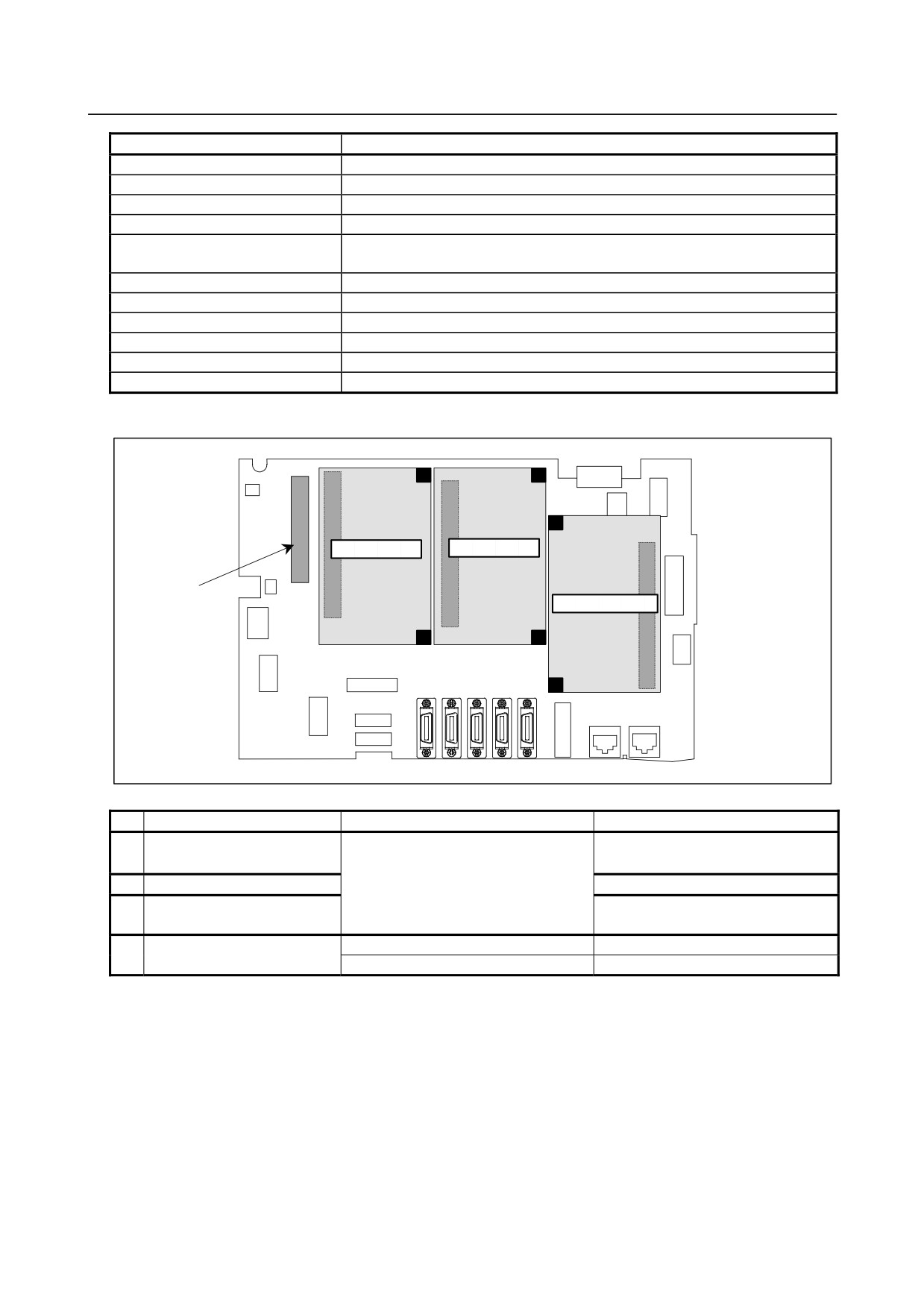
• Card and back panel mounting location
Connector
Connector
(1) Servo card
(2) CPU card
(3) Back panel (with
(4) GUI card
power supply)
Connector
№
Name
Specification
Remark
(1)
Servo card
See Subsection 2.4.1, “LCD-mounted
Type Control Unit (8.4” LCD Unit and
10.4” LCD Unit A)”.
(2)
CPU card
(3)
Back panel (with power
supply)
(4)
GUI card
A20B-3300-0670
A20B-3300-0671
- 190 -
B-64485EN/01
2.CONTROL UNIT HARDWARE
-
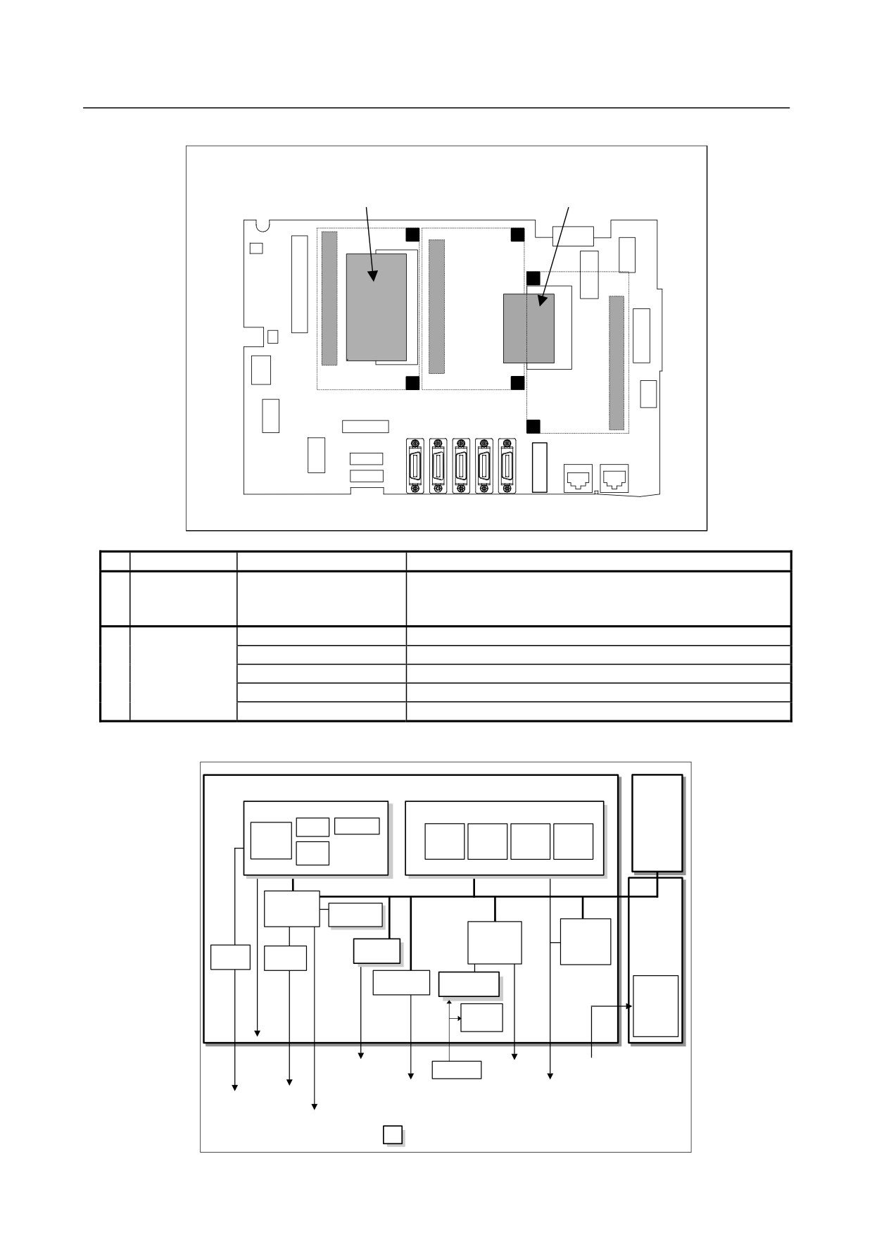
FROM/SRAM module and compact flash card mounting location
(1) FROM/SRAM module
(2) Compact flash card
Connector
Connector
Connector
No.
Name
Specification
Remark
(1)
FROM/SRAM
A20B-3900-0260
The FROM stores various control software programs, user
module
software programs, and so forth.
The SRAM is a battery-backed memory module.
(2)
Compact flash
A87L-0001-0173#128MBD
Total capacity: 128MB
card
A87L-0001-0173#256MBD
Total capacity: 256MB
A87L-0001-0173#512MBD
Total capacity: 512MB
A87L-0001-0173#001GBD
Total capacity: 1GB
A87L-0001-0173#002GBD
Total capacity: 2GB
-
Block diagram
Optional
Main board
board
GUI card
CPU card
DRAM
Display control
CPU
CPU
DRAM
BOOT
I/O Link
software
control
BOOT
software
Peripheral
control 2
Compact
Flash card
Peripheral
I/O Link i,
control 1
I/O Link
Back panel
Servo card
control
Ethernet
USB
control
control
Communication
FROM/SRAM
function
module
Power
supply
Calendar
function
Display unit
RS-232C
FSSB
Battery
MDI
24VDC
HDI
Ethernet (Multi-function
I/O Link i
USB
Ethernet)
I/O Link
Ethernet
(Embedded
Ethernet)
Memory card
: Detachable card or module
- 191 -