FANUC Series 30i-MODEL B, 31i-MODEL B, 32i-MODEL B. MAINTENANCE MANUAL - page 2

1.DISPLAY AND OPERATION
B-64485EN/01
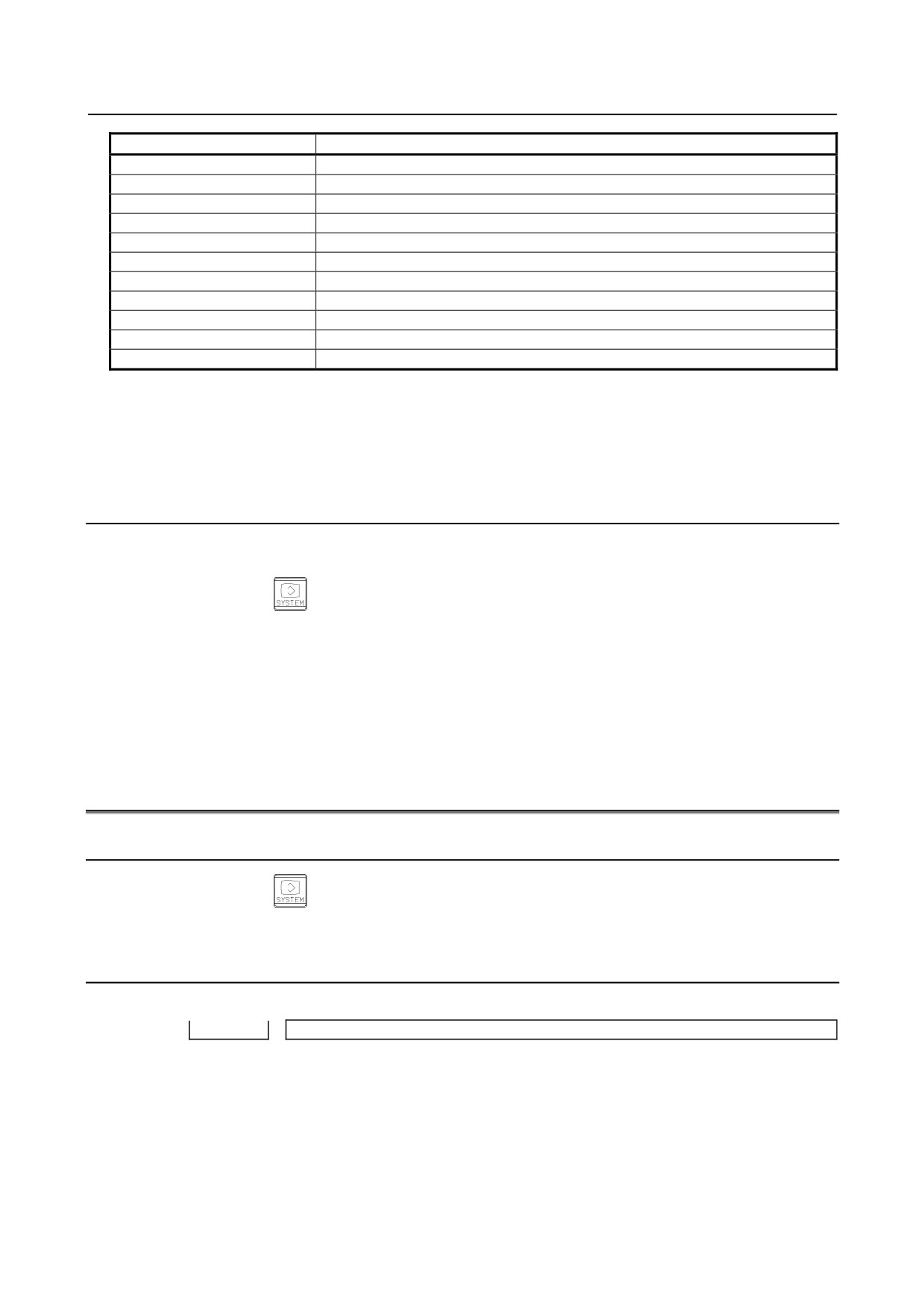
System
Software type
BOOT
Boot system
PMC(SYSTEM)
PMC function
PMC(LADDER1)
PMC ladder for path 1
PMC(LADDER2)
PMC ladder for path 2
PMC(LADDER3)
PMC ladder for path 3
PMC(LAD DCS)
Dual check safety PMC ladder
CLB(SYSTEM)
System software for C language board
CLB(USER)
User software for C language board
SERVO
Digital servo software (up to ten programs displayed)
SPINDLE-1
Spindle 1
SPINDLE-2
Spindle 2
SPINDLE-3
Spindle 3
SPINDLE-4
Spindle 4
SPINDLE-5
Spindle 5
SPINDLE-6
Spindle 6
SPINDLE-7
Spindle 7
SPINDLE-8
Spindle 8
SPINDLE-9
Spindle 9
SPINDLE-10
Spindle 10
SPINDLE-11
Spindle 11
SPINDLE-12
Spindle 12
SPINDLE-13
Spindle 13
SPINDLE-14
Spindle 14
SPINDLE-15
Spindle 15
SPINDLE-16
Spindle 16
GRAPHIC
Graphic function
GRAPHIC1
Graphic function
GRAPHIC2
Graphic function
MACRO EXE1
Macro executor 1
MACRO EXE2
Macro executor 2
MACRO EXE3
Macro executor 3
MACRO EXE4
Macro executor 4
MACRO EXE5
Macro executor 5
MACRO EXE6
Macro executor 6
MACRO EXE7
Macro executor 7
MACRO EXE8
Macro executor 8
MACRO EXE9
Macro executor 9
MACRO EXE10
Macro executor 10
MACRO EXE11
Macro executor 11
MACRO EXE12
Macro executor 12
MACRO EXE13
Macro executor 13
MACRO EXE14
Macro executor 14
MACRO EXE15
Macro executor 15
MACRO EXE16
Macro executor 16
MACRO EXE17
Macro executor 17
MACRO EXE18
Macro executor 18
MACRO EXE19
Macro executor 19
MACRO EXE20
Macro executor 20
CEXELIB
Library for C Language Executor
CEXEAPL
Application for C Language Executor
MGI(LIB)
Library for MANUAL GUIDE i
MGI(SYSTEM)
System software for MANUAL GUIDE i
MGI(MACRO M)
Macro software for MANUAL GUIDE i (M series)
MGI(MACRO T)
Macro software for MANUAL GUIDE i (T series)
- 12 -
B-64485EN/01
1.DISPLAY AND OPERATION
System
Software type
EMBED ETHER
Control software for embedded Ethernet function
PROFI SOFT
Software for PROFIBUS function
PROFI MASTER
Control software for PROFIBUS master function
PROFI SLAVE
Control software for PROFIBUS slave function
DEVNT SOFT
Software for DeviceNet function
DEVNT MASTER
Control software for DeviceNet master function
DEVNT SLAVE
Control software for DeviceNet slave function
ETHERNET
Control software for fast Data Server
CMB(SYSTEM)
Customers' board system software
CMB(USER)
Customers' board user software
USB SOFT
Control software for USB function
• Display of macro executor
The series and edition are displayed for each number specified at the time of P-CODE macro
creation.
Up to 20 types of macro executor are displayed.
1.2.4
Outputting System Configuration Data
Data displayed on the system configuration screen can be output to an input/output device.
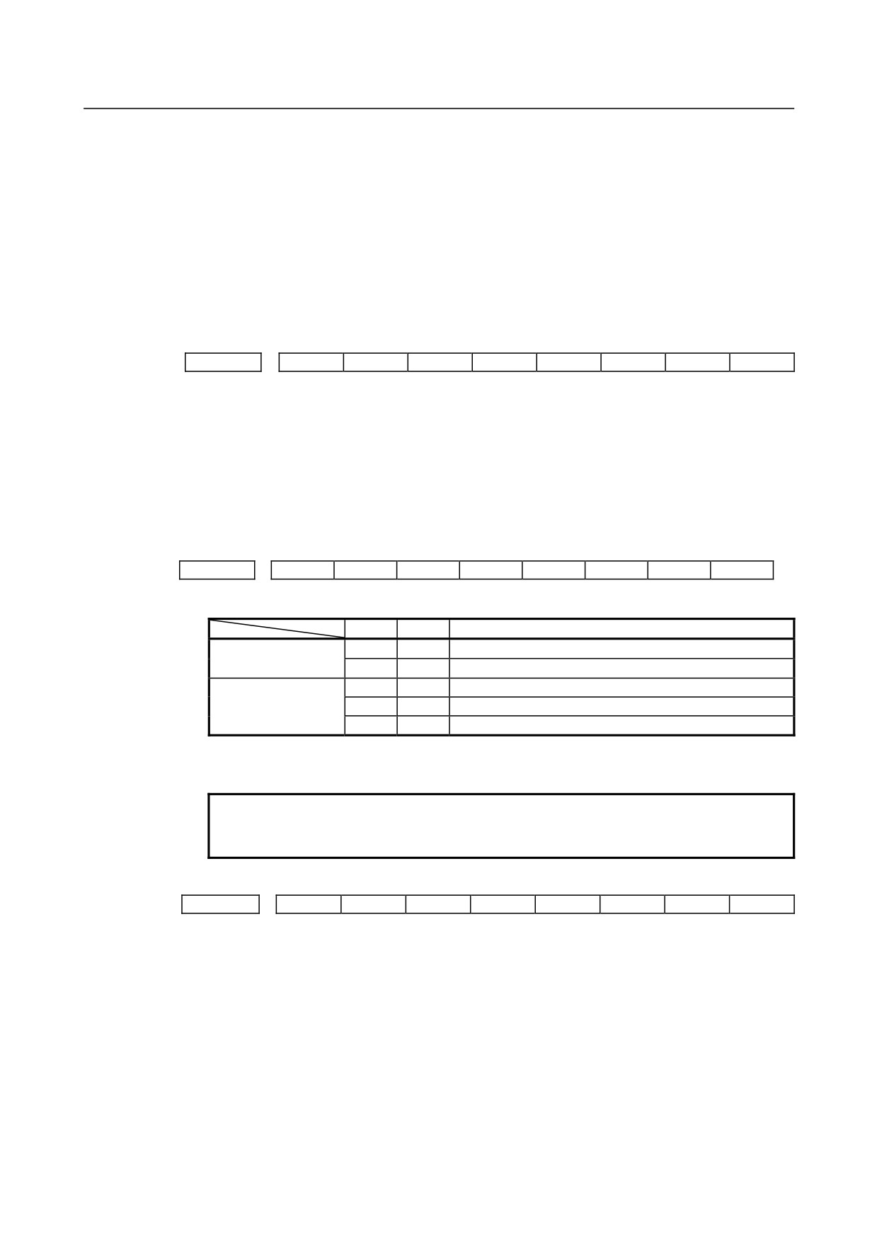
(1) Press function key
(2) Press the EDIT switch on the machine operator's panel.
(3) Press soft key [SYSTEM] to display the system configuration screen.
(4) Press soft key [(OPRT)] and select soft key [PUNCH].
(5) Press soft key [EXCE].
(6) Data is output to the output device selected by parameter No. 20.
Data is output to a file named SYS_CONF.TXT.
1.3
DIAGNOSIS FUNCTION
1.3.1
Displaying Diagnosis Screen
(1) Press function key
(2) Press soft key [DGNOS], then a diagnosis screen is displayed.
1.3.2
Contents Displayed
Causes when the machine does not travel in spite of giving a command
Diagnosis
0
CNC internal state 1
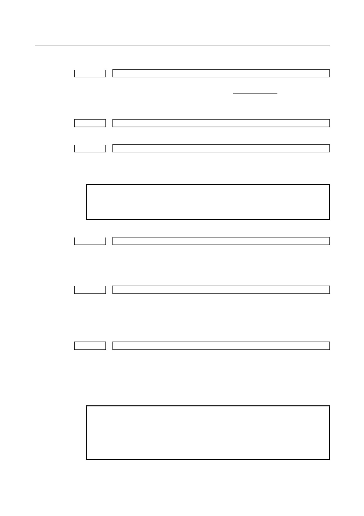
[Data type] Bit
NAME
Internal state when "1" is displayed
INPOSITION CHECK
In-position check is being done.
FEEDRATE OVERRIDE 0%
Feedrate override is 0%.
JOG FEED OVERRIDE 0%
Jog feedrate override is 0%.
INTER/START LOCK ON
Interlock/start lock is on.
SPEED ARRIVAL ON
The system is waiting for the speed arrival signal to turn
on.
- 13 -

1.DISPLAY AND OPERATION
B-64485EN/01
WAIT REVOLUTION
The system is waiting for the spindle one-rotation signal
in threading.
STOP POSITION OCDER The system is waiting for the rotation of the position
coder in spindle feed per revolution.
FEED STOP
A feed stop was made.
Diagnosis
2
Dwell execution state
When a dwell is being executed, "1" is displayed.
Diagnosis
8
CNC internal state 2
[Data type] Bit
NAME
Internal state when "1" is displayed
FOREGROUND READING
Data is being input in the foreground.
BACKGROUND READING
Data is being input in the background.
Reader/puncher interface output state
Diagnosis
10
Reader/puncher interface output state
When data is being output through the reader/puncher interface, "1" is indicated.
State of TH alarm
Diagnosis
30
TH alarm character count (foreground edit)
[Data type] 2-word axis
The position where the TH alarm occurred in foreground input is indicated by the number
of characters from the beginning of the block.
Diagnosis
31
TH alarm character code (foreground edit)
[Data type] 2-word axis
The character code of the character at which the TH alarm occurred in foreground input is
indicated.
Diagnosis
32
TH alarm character count (background edit)
[Data type] 2-word axis
The position where the TH alarm occurred in background input is indicated by the
number of characters from the beginning of the block.
Diagnosis
33
TH alarm character code (background edit)
[Data type] 2-word axis
The character code of the character at which the TH alarm occurred in background input
is indicated.
Display language of the CNC screen
Diagnosis
43
Number of the current display language of the CNC screen
[Data type] Byte
The number of the current display language of the CNC screen is indicated.
The correspondence between languages and numbers is show below.
0
:
English
1
:
Japanese
2
:
German
3
:
French
4
:
Chinese (traditional characters)
5
:
Italian
6
:
Korean
7
:
Spanish
8
:
Dutch
- 14 -
B-64485EN/01
1.DISPLAY AND OPERATION
9
:
Danish
10
:
Portuguese
11
:
Polish
12
:
Hungarian
13
:
Swedish
14
:
Czech
15
:
Chinese (simplified characters)
16
:
Russian
17
:
Turkish
Details of serial Pulsecoder
#7
#6
#5
#4
#3
#2
#1
#0
Diagnosis
200
OVL
LV
OVC
HCA
HVA
DCA
FBA
OFA
#0 OFA Overflow alarm
#1 FBA Disconnection alarm
#2 DCA Discharge alarm
#3 HVA Overvoltage alarm
#4 HCA Abnormal current alarm
#5 OVC Over current alarm
#6
LV Insufficient voltage alarm
#7 OVL Overload alarm
#7
#6
#5
#4
#3
#2
#1
#0
Diagnosis
201
ALD
PCR
EXP
#4 EXP
#7 ALD
ALD
EXP
Description
Overload alarm
0
-
Motor overheat
1
-
Amplifier overheat
Disconnection alarm
1
0
Built-in Pulsecoder (hard)
1
1
Disconnection of separated type Pulsecoder (hard)
0
0
Disconnection of Pulsecoder (software)
#6 PCR The one-rotation signal of the position detector was caught before a manual reference
position return is performed. Since the manual reference position return grid was
established, a manual reference position return is enabled.
NOTE
This bit is valid only when the operation of the manual reference
position return mode is started.
#7
#6
#5
#4
#3
#2
#1
#0
Diagnosis
202
CSA
BLA
PHA
RCA
BZA
CKA
SPH
#0 SPH Serial Pulsecoder or feedback cable is faulty.
Counting of feedback cable is erroneous.
#1 CKA Serial Pulsecoder is faulty.
Internal block stopped.
#2 BZA Battery voltage became 0.
Replace the battery and set the reference position.
#3 RCA Serial Pulsecoder is faulty.
The speed was incorrectly counted.
#4 PHA Serial Pulsecoder or feedback cable is erroneous.
Counting of feedback cable is erroneous.
#5 BLA Battery voltage is low (warning)
#6 CSA Hardware of serial Pulsecoder is abnormal
- 15 -
1.DISPLAY AND OPERATION
B-64485EN/01
#7
#6
#5
#4
#3
#2
#1
#0
Diagnosis
203
DTE
CRC
STB
PRM
#4 PRM A parameter failure was detected on the digital servo side. See the cause and
measure described in diagnosis No. 352.
#5 STB Communication failure of serial Pulsecoder.
Transferred data is erroneous.
#6 CRC Communication failure of serial Pulsecoder.
Transferred data is erroneous.
#7 DTE Communication failure of serial Pulsecoder.
There is no response for communication.
#7
#6
#5
#4
#3
#2
#1
#0
Diagnosis
204
OFS
MCC
LDA
PMS
#3 PMS Feedback is not correct due to faulty serial Pulsecoder C or feedback cable.
#4 LDA Serial Pulsecoder LED is abnormal
#5 MCC Contacts of MCC of servo amplifier is melted.
#6 OFS Abnormal current value result of A/D conversion of digital servo
Details of separate serial Pulsecoder alarms
#7
#6
#5
#4
#3
#2
#1
#0
Diagnosis
205
OHA
LDA
BLA
PHA
CMA
BZA
PMA
SPH
#0 SPH A soft phase data error occurred in the separate Pulsecoder.
#1 PMA A pulse error occurred in the separate Pulsecoder.
#2 BZA The battery voltage for the separate Pulsecoder is zero.
#3 CMA A count error occurred in the separate Pulsecoder.
#4 PHA A phase data error occurred in the separate linear scale.
#5 BLA A low battery voltage occurred in the separate Pulsecoder.
#6 LDA An LED error occurred in the separate Pulsecoder.
#7 OHA Overheat occurred in the separate Pulsecoder.
#7
#6
#5
#4
#3
#2
#1
#0
Diagnosis
206
DTE
CRC
STB
#5 STB A stop bit error occurred in the separate Pulsecoder.
#6 CRC A CRC error occurred in the separate Pulsecoder.
#7 DTE A data error occurred in the separate Pulsecoder.
Details of invalid servo parameter alarms (on the CNC side)
When servo alarm No. 417 is issued, and diagnosis No. 203#4 = 0, its cause is indicated.
When diagnosis No. 203#4 = 1, see diagnosis No. 352.
#7
#6
#5
#4
#3
#2
#1
#0
Diagnosis
280
DIR
PLS
PLC
MOT
#0 MOT The motor type specified in parameter No. 2020 falls outside the predetermined range.
#2 PLC The number of velocity feedback pulses per motor revolution, specified in parameter No.
2023, is zero or less. The value is invalid.
#3 PLS The number of position feedback pulses per motor revolution, specified in parameter No.
2024, is zero or less. The value is invalid.
#4 DIR The wrong direction of rotation for the motor is specified in parameter No. 2022 (the
value is other than 111 or -111).
#7
#6
#5
#4
#3
#2
#1
#0
Diagnosis
281
TDM
#0 TDM Four-winding motor drive (bit 7 of parameter No. 2211) or two-winding motor drive (bit
6 of parameter No. 2211) is enabled when no option for tandem control is present.
- 16 -
B-64485EN/01
1.DISPLAY AND OPERATION
Position error amount
Diagnosis
300
Position error of an axis in detection unit
Feed rate [mm/min] × 100
1
Position error =
60 × servo loop gain [1/sec]× Detection unit
Machine position
Diagnosis
301
Distance from reference position of an axis in detection unit
Distance from the end of the deceleration dog to the first grid point
Diagnosis
302
Distance from the end of the deceleration dog to the first grid point
[Data type] Real axis
[Unit of data] Machine unit
[Valid data range] 0 to ±99999999
NOTE
For the reference position setting without a dog, the distance from
the beginning of the reference position setting without a dog to the
first grid point is assumed.
Reference counter
Diagnosis
304
Reference counter amount in each axis
[Data type] 2-word axis
[Unit of data] Detection unit
[Valid data range] -99999999 to 99999999
Motor temperature information
Diagnosis
308
Servo motor temperature (°C)
[Data type] Byte axis
[Unit of data] °C
[Valid data range] 0 to 255
The temperature of the coil of the servo motor is indicated. When the temperature reaches
140°C, a motor overheat alarm is issued.
Diagnosis
309
Pulsecoder temperature (°C)
[Data type] Byte axis
[Unit of data] °C
[Valid data range] 0 to 255
The temperature of the printed circuit board in the Pulsecoder is indicated. When the
temperature reaches 100°C (approximately 85°C for the temperature of atmosphere in the
Pulsecoder), a motor overheat alarm is issued.
NOTE
1 Temperature information has the following error:
•
50°C to 160°C ±5°C
•
160°C to 180°C ±10°C
2 The temperature at which an overheat alarm is issued has an error
of up to 5°C.
- 17 -
1.DISPLAY AND OPERATION
B-64485EN/01
Cause that sets bit 4 (APZ) of parameter No. 1815 to 0
You can find the cause that sets bit 4 (APZ) of parameter No. 1815 to 0 by checking diagnosis Nos. 310
and 311.
Once diagnosis No. 310 or 311 is set to 1, this setting is kept unchanged until the zero point of the
absolute position detector of the corresponding axis is set again. Possible causes that set APZ to 0 are as
follows:
#7
#6
#5
#4
#3
#2
#1
#0
Diagnosis
310
DTH
ALP
BZ2
BZ1
PR2
PR1
#0 PR1 One of the following parameters was changed:
No.1815#0, No.1815#1, No.1815#6, No.1817#3, No.1820, No.1821, No.1822, No.1823,
No.1850, No.1868, No.1869, No.1874, No.1875, No.1876, No.1883, No.1884, No.2022,
No.2084, No.2085, No.2179
#1 PR2 Bit 1 (ATS) of parameter No. 8303 was changed. Alternatively, when bit 7 (SMA) of
parameter No. 8302 was set to 1, APZ of the axis to be synchronized together was set to
0.
#2 BZ1 A battery voltage of 0 V was detected. (Inductosyn)
#3 BZ2 A battery voltage of 0 V was detected. (Separate position detector)
#5 ALP The zero point was set by MDI when the α pulse coder had not rotate one or more turns.
Alternatively, the CNC could not obtain a correct value from the absolute pulse coder.
#6 DTH An axis detach operation was performed by the controlled-axis detach signal DTCH
<G124> or by setting bit 7 (RMV) of parameter No. 0012.
#7
#6
#5
#4
#3
#2
#1
#0
Diagnosis
311
DUA
XBZ
GSG
AL4
AL3
AL2
AL1
#0 AL1 An SV alarm (SV301 to SV305) was issued.
#1 AL2 When bit 1 (CRF) of parameter No. 1819 was set to 1, alarm SV0445, “SOFT
DISCONNECT ALARM”, SV0447,
“HARD DISCONNECT(EXT)”, or SV0646,
“ABNORMAL ANALOG SIGNAL(EXT)”, was detected.
#2 AL3 A battery voltage of 0 V was detected. (Built-in serial Pulsecoder)
#3 AL4 Alarm SV0367, “COUNT MISS(INT)”, was detected.
#4 GSG The status of broken-wire alarm ignore signal NDCAL (G202) changed from 1 to 0.
#5 XBZ A battery voltage of 0 V or alarm SV0382, “COUNT MISS(EXT)”, was detected.
(Separate serial position detector)
#6 DUA When bit 1 (CRF) of parameter No. 1819 was set to 1, alarm SV0421, “EXCESS
ERROR(SEMI-FULL)”, was detected.
Details of invalid servo parameter setting alarms (on the servo side)
Diagnosis
352
Detail number for invalid servo parameter setting alarm
Indicates information that can be used to identify the location (parameter) and cause of an
invalid servo parameter setting alarm (servo alarm No. 417).
This diagnosis information is valid when the following conditions are satisfied.
• Servo alarm No. 417 has occurred.
• Bit 4 of diagnosis No. 203 (PRM) = 1
See the following table for the displayed detail numbers and the corresponding causes.
For further detail information that could be used to take measures, refer to FANUC AC
Servo Motor αis/αi/βis series Parameter Manual (B-65270EN).
• Detailed descriptions about invalid servo parameter setting alarms
Detail
Parameter No.
Cause
Action
number
Parameter settings related to learning
Change the parameter settings so that
83
2019
control are illegal
they fall in the applicable range.
→ See Supplementary.
- 18 -

B-64485EN/01
1.DISPLAY AND OPERATION
Detail
Parameter No.
Cause
Action
number
When initialization bit 0 is set to 1, the
Correct the number of velocity pulses so
0233
2023
number of velocity pulses exceeds 13100.
that it is within 13100.
Set 512 or a greater number as the
When a DD motor is used, a value smaller
number of velocity pulses, or disable the
0234
2023
than 512 is set as the number of velocity
DD motor.
pulses.
Bit 0 of parameter No. 2300=0
Correct the number of position pulses so
When initialization bit 0 is set to 1, the
that it is within 13100.
0243
2024
number of position pulses exceeds
Use the position feedback pulse
13100.
conversion coefficient (parameter No.
2185).
0434
The internal value of the velocity loop
Decrease the value of the velocity loop
2043
0435
integral gain overflowed.
integral gain parameter.
Use the function for changing the internal
0443
format of the velocity loop proportional
The internal value of the velocity loop
0444
2044
gain (bit 6 of parameter No. 2200).
proportional gain overflowed.
0445
Alternatively, decrease the parameter
setting.
0474
The internal value of the observer
Correct the setting to
2047
0475
parameter (POA1) overflowed.
(−1) × (desired value)/10.
Decrease the setting to the extent that the
0534
The internal value of a parameter related
2053
illegal servo parameter setting alarm is
0535
to dead zone compensation overflowed.
not caused.
Decrease the setting to the extent that the
0544
The internal value of a parameter related
2054
illegal servo parameter setting alarm is
0545
to dead zone compensation overflowed.
not caused.
0694
0695
The internal value of the velocity
Decrease the velocity feed-forward
2069
0696
feed-forward coefficient overflowed.
coefficient.
0699
0754
The setting for this parameter has
This parameter is not used at present. Set
2075
0755
overflowed.
0.
0764
The setting for this parameter has
This parameter is not used at present. Set
2076
0765
overflowed.
0.
Set a positive value as the flexible feed
A positive value is not set as the flexible
gear numerator.
feed gear numerator.
Alternatively, satisfy the following
0843
2084
Alternatively, the following condition
condition: Feed gear numerator ≤
exists: Feed gear numerator >
denominator × 16
denominator × 16
(except for phase A-/B-specific separate
detector).
A positive value is not set as the flexible
Set a positive value as the flexible feed
0853
2085
feed gear denominator.
gear denominator.
For an axis with a serial type separate
For an axis with a serial type separate
detector, the upper limit of the machine
0883
2088
detector, a value exceeding 100 is set as
velocity feedback coefficient is 100.
the machine velocity feedback coefficient.
Correct the coefficient so that it does not
exceed 100.
Decrease the machine velocity feedback
0884
coefficient.
The internal value of the machine velocity
0885
2088
Alternatively, use the vibration-damping
feedback coefficient overflowed.
0886
control function that has an equivalent
effect.
- 19 -

1.DISPLAY AND OPERATION
B-64485EN/01
Detail
Parameter No.
Cause
Action
number
0994
Disable the N pulse suppression function.
The internal value for N pulse
0995
2099
Alternatively, decrease the parameter
suppression overflowed.
0996
setting so that no overflow will occur.
The retract distance related to an
abnormal load differs between the L and M
Set the same value for both the L and M
1033
2103
axes (if the same-axis retract function is in
axes.
use).
Although a linear motor is used, the AMR
1123
2112
conversion coefficient parameter is not
Set the AMR conversion coefficient.
input.
2118
The dual position feedback conversion
Specify the dual position feedback
1182
2078
coefficient has not been specified.
conversion coefficient.
2079
When a small value is set as the number
1284
of velocity pulses, the internal value of a
Decrease the value in this parameter to
2128
1285
parameter related to current control
the extent that the alarm is not caused.
overflows.
When a large value is set as the number
When the value set in this parameter is
1294
of velocity pulses, the internal value of a
2129
resolved to the form a × 256 + b, set a
1295
parameter related to current control
smaller value in a again.
overflows.
Enlarge the AMR offset setting range (bit
The AMR offset setting value of a linear
1393
2139
0 of parameter N. 2270=1) to input a
motor exceeds ±45.
value within a range of ±60.
1454
1455
Velocity feed-forward coefficient for
Decrease the velocity feed-forward
2145
1456
cutting overflowed.
coefficient.
1459
Only 6 or less can be specified in this
A value greater than 6 is specified in this
1493
2149
parameter. Change the setting to 6 or
parameter.
below 6.
1503
2150
A value equal to or greater than 10 is set.
Set a value less than 10.
Bit 6 of No. 2212 or bit 6 of No. 2213 is set
Set bit 6 of No. 2212 or bit 6 of No. 2213
1786
2178
to 1, and No. 2621=0 is set.
to 0.
A negative value or a value greater than
Set a positive value less than the setting
1793
2179
the setting of parameter No. 1821 is set.
of parameter No. 1821.
A negative value or a value greater than
Set a positive value less than the setting
1853
2185
the setting of parameter No. 2023 is set.
of parameter No. 2023.
If pole detection is enabled (bit 7 of No.
2213=1) and a non-binary detector is
enabled (bit 0 of No. 2220=1), an illegal
servo parameter setting alarm is issued
when any of the following is set:
Set the AMR conversion coefficients
2203
2220#0
- AMR conversion coefficient 1 ≤ 0
correctly.
- AMR conversion coefficient 2 ≤ 0
- AMR conversion coefficient 2 > 512
(The settable range is 1 (2 poles) to 512
(1024 poles).)
This alarm is issued when a setting is
made to neglect the invalid setting of the
parameter for the feed-forward timing
2243
2224#5
Use either one.
adjustment function (bit 5 of No. 2224=1)
and a command for nano interpolation is
issued.
- 20 -

B-64485EN/01
1.DISPLAY AND OPERATION
Detail
Parameter No.
Cause
Action
number
When the lifting function against gravity is
Take one of the following actions:
enabled (bit 7 of No. 2298=1) or the
1) Set a value in parameter No. 2263.
post-servo-off travel distance monitor
2) Disable the lifting function against
function is enabled (bit 5 of No. 2278=1),
gravity and the post-servo-off travel
2632
2263
the function for enabling the CNC software
distance monitor function.
to post the detection unit to the servo
3) Use CNC software that supports the
software is not supported and the setting
function for enabling the detection unit
of the detection unit (No. 2263) is
to be posted to the servo software.
disabled.
2277#5,6,7
When the first SDU unit is not used
2278#0,2,4
(No.24096=0), a setting is made to
Check the FSSB setting (No.24096) or the
2780
24096
connect a detector (acceleration sensor,
detector setting (bits 0, 2, and 4 of No.
temperature detection circuit, or analog
2278).
check interface unit) to the first SDU unit.
2277#5,6,7
When the second SDU unit is not used
2278#1,3,4
(No.24097=0), a setting is made to
Check the FSSB setting (No.24097) or the
24097
connect a detector (acceleration sensor,
2781
detector setting (bits 1, 3, and 4 of No.
temperature detection circuit, or analog
2278).
check interface unit) to the second SDU
unit.
2277#5,6,7
Any of the following settings is made:
2278#0,4
• For use with the first SDU unit, both of
24096
an acceleration sensor and
temperature detection circuit are
enabled.
Check the settings of the acceleration
2782
• Settings are made to use the first
sensor and temperature detection circuit.
SDU unit (No.24096>0), disable an
acceleration sensor (bits 5, 6, 7 of No.
2277=0,0,0), and read acceleration
data from the second unit (bit 1 of No.
2278=1).
Any of the following settings is made:
• For use with the second SDU unit,
both of an acceleration sensor and
temperature detection circuit are
2277#5,6,7
enabled.
Check the settings of the acceleration
2783
2278#1,4
• Settings are made to use the second
sensor and temperature detection circuit.
24097
SDU unit (No.24097>0), disable an
acceleration sensor (bits 5, 6, 7 of No.
2277=0,0,0), and read acceleration
data from the second unit (bit 1 of No.
2278=1).
At the time of full-closed system setting, a
1815#1
detector other than a separate position
2784
2277#5,6,7
Modify the setting of the detector.
detector is connected (with the first/second
2278#0,1,4
SDU unit).
At the time of full-closed system setting, a
1815#1
detector other than a separate position
2785
2277#5,6,7
Modify the setting of the detector.
detector is connected (with the first SDU
2278#0,4
unit).
At the time of full-closed system setting, a
1815#1
detector other than a separate position
2786
2277#5,6,7
Modify the setting of the detector.
detector is connected (with the second
2278#1,4
SDU unit).
- 21 -

1.DISPLAY AND OPERATION
B-64485EN/01
Detail
Parameter No.
Cause
Action
number
Only one temperature detection circuit can
A setting is made to connect two
be connected. Modify the setting so that
2787
2278#0,#1
temperature detection circuits.
data is read from one of the first and
second SDU units.
1815#1
2277#5,6,7
Only one temperature detection circuit can
2278#4
A setting is made to connect two
be connected. Modify the setting so that
2788
2278#0,1
temperature detection circuits.
data is read from one of the first and
24096
second SDU units.
24097
Replace the αiCZ detection circuit and
linear motor position detection circuit with
The αiCZ detection circuit and linear
those circuits that support overheat signal
3002
2300#3,#7
motor position detection circuit do not
connection. Alternatively, modify the
support overheat signal connection.
setting so that the overheat signal is read
from a DI signal (bit 3 of parameter No.
2300=0).
• When bit 2 of No. 2301=1
• When bit 2 of No. 2301=1
Hardware (PS, SV) that does not
Set bit 2 of No. 2301 to 0.
support DC link voltage information
output is connected, but bit 2 of No.
3012
2301#2,#7
2301 is set to 1.
• When bit 7 of No. 2301=1
• When bit 7 of No. 2301=1
The CNC software does not support
Use CNC software that supports the
the torque control setting range
function.
extension function.
3553
2355
The value 4 or a smaller number is set.
Set the value 5 or a greater number.
3603
Set the value 96 or a greater number.
2113
Alternatively, if no resonance elimination
2360
3603
The value 95 or smaller number is set.
filter is used, set all of the center
2363
frequency, band width, and dumping value
2366
to 0.
3603
2366
The value 4 or a smaller number is set.
Set the value 5 or a greater number.
3663
4553
2455
A negative value is set.
Set the value 0 or a greater number.
4563
2456
A value not within 0 to 12 is set.
Set a value within 0 to 12.
A positive value is not set in the reference
8213
1821
Set a positive value in this parameter.
counter capacity parameter.
• Set a value other than 0 (when setting
8254
= 0).
A position gain of 0 is set, or the internal
8255
1825
• Use the function for automatic format
position gain value has overflowed.
8256
change for position gain setting range.
(Set bit 6 of parameter No. 2209 to 1.)
1815#1
At the time of full-closed system setting,
9053
24096
Set a separate detector interface unit.
no separate detector interface unit is set.
24097
10010
The internal value of a parameter used to
Do not use the runaway detection function
10016
2200#0
detect runaway has overflowed.
(specify bit 0 = 1).
10019
Illegal control cycle setting
Correct this parameter related to interrupt
10033
2004
This error occurs if automatic modification
cycle setting.
is carried out for the control cycle.
When a linear motor is used, the scale
When the linear motor is used, the scale
10053
2018#0
reverse connection bit is set.
reverse connection bit cannot be used.
- 22 -
B-64485EN/01
1.DISPLAY AND OPERATION
Detail
Parameter No.
Cause
Action
number
When you use the current amplifier
continuously, set the function bit shown to
The amplifier used does not support the
the left to 0.
10062
2209#4
HC alarm prevention function.
When using the HC alarm prevention
function, use an appropriate amplifier that
supports the function.
Different control cycles are set within one
Set the same control cycle for axes
servo CPU.
controlled by one servo CPU.
2004
10092
Replace the detector with a detector
2013#0
When HRV4 is enabled, a detector that
10093
supporting HRV4. Alternatively, disable
2014#0
does not support HRV4 is used.
HRV4.
Replace the servo amplifier with a servo
When HRV4 is enabled, a servo amplifier
amplifier supporting HRV4. Alternatively,
that does not support HRV4 is connected.
disable HRV4.
2004
The Series 30i does not allow HRV1
10103
HRV1 is set.
2013#0
setting. Set HRV2, HRV3 or HRV4.
An axis for which HRV3 is specified exists
Current cycle mismatch alarm.
on the same optical cable. Review the
10113
2013#0
This alarm is issued if the specified current
placement of the amplifier, or disable
cycle does not match the actual setting.
HRV3.
Alarm for indicating the disability of HRV3
setting.
Eliminate the cause of the disability in
10123
2013#0
This alarm is issued when the axis
setting the other axis. Alternatively, cancel
supports HRV3 but the other axis of the
the HRV3 setting.
pair does not support HRV3.
When HRV4 is set, this alarm is issued if
any of the following conditions is met.
• Servo software not supporting HRV4
is used.
• The same FSSB system includes
2013#0
Eliminate the causes listed on the left.
10133
axes with HRV4 setting and axes with
2014#0
Alternatively, cancel the HRV4 setting.
HRV2 or HRV3 setting.
• The limitation in the number of axes is
not observed.
(In HRV4 control, one axis/DSP is
set.)
This alarm is issued when HRV3 or HRV4
2013#0
HRV3 or HRV4 is unusable for the axis on
10133
is set, but the amplifier does not support
2014#0
which the alarm was issued.
these control types.
The ID of the detector connected to the
2277#5,6,7
Check the detector-related parameter or
10202
first SDU unit differs from the parameter
2278#0,2,4
the state of detector connection.
setting.
The ID of the detector connected to the
2277#5,6,7
Check the detector-related parameter or
10212
second SDU unit differs from the
2278#1,3,4
the state of detector connection.
parameter setting.
Supplementary: Details of an illegal learning control parameter
Set parameter No. 2115 to 0, and parameter No. 2151 to 6265 to change the value of DGN No. 353 to a
binary number. You can find a detailed cause from the bit position of the obtained binary number at
which 1 is set.
Position
Cause
B3
The band-pass filter (No. 2512) is not in the range.
- 23 -
1.DISPLAY AND OPERATION
B-64485EN/01
Position
Cause
B4
The profile number (No. 2511) is not in the range.
B5
The specified data period (No. 251, 2519, 2521, 2523, or 2525) is not in the range.
B6
The total number of profiles (No. 2510) is not in the range.
B7
This alarm is issued when G05 starts during a memory clear operation.
B8
This alarm is issued when the total number of profiles (No. 2510) is not 0, and the profile number
(No. 2511) is 0.
B9
This alarm is issued when the automatically-set thinning shift value exceeds the range because the
specified data period is too long.
Diagnosis
355
Communication alarm ignore counter (separate type)
Diagnosis
356
Link processing counter (built-in type)
Diagnosis
357
Link processing counter (separate type)
The number of times a communication error occurred during serial communication with
the detector is indicated.
Data transmitted during communication is guaranteed unless another alarm occurs.
However, if the counter value indicated in this diagnosis information increases in a short
period, there is a high probability that serial communication is disturbed by noise. So,
take sufficient measures to prevent noise.
* For details, refer to a relevant manual on FANUC SERVO MOTOR αi series.
Diagnosis
358
V ready-off information
This information is provided to analyze the cause of the V ready-off alarm (servo alarm
SV0401).
Convert the indicated value to a binary representation, and check bits 5 to 14 of the
binary representation.
When amplifier excitation is turned on, these bits are set to 1 sequentially from the lowest
bit, which is bit 5. If the amplifier is activated normally, bits 5 to 14 are all set to 1.
Therefore, check the bits sequentially from the lowest bit to find the first bit that is set to
0. This bit indicates that the corresponding processing could not be completed and so the
V ready-off alarm was caused.
#15
#14
#13
#12
#11
#10
#09
#08
SRDY
DRDY
INTL
CRDY
#07
#06
#05
#04
#03
#02
#01
#00
*ESP
# 06
*ESP Converter emergency stop state released
# 10
CRDY Converter ready
# 12
INTL DB relay released
# 13
DRDY Amplifier ready (amplifier)
# 14
SRDY Amplifier ready (software)
* For details, refer to a relevant manual on FANUC SERVO MOTOR αi series.
Diagnosis
359
Communication alarm neglect counter (built-in type)
The diagnosis information is the same as that of diagnosis No. 355.
See the descriptions in diagnoses No.355 to 357.
- 24 -
B-64485EN/01
1.DISPLAY AND OPERATION
Diagnosis
360
Cumulative value of specified pulses (NC)
[Data type] 2-word
[Unit of data] Detection unit
[Valid data range] -99999999 to 99999999
Cumulative value of move commands distributed from the CNC since power-on is
indicated.
Diagnosis
361
Compensation pulses (NC)
[Data type] 2-word
[Unit of data] Detection unit
[Valid data range] -99999999 to 99999999
Cumulative value of compensation pulses
(backlash compensation, pitch error
compensation, and so on) distributed from the CNC since power-on is indicated.
Diagnosis
362
Cumulative value of specified pulses (SV)
[Data type] 2-word
[Unit of data] Detection unit
[Valid data range] -99999999 to 99999999
Cumulative value of move pulses and compensation pulses received by the servo system
since power-on is indicated.
Diagnosis
363
Cumulative feedback (SV)
[Data type] 2-word
[Unit of data] Detection unit
[Valid data range] -99999999 to 99999999
Cumulative value of positional feedback pulses the servo system received from the pulse
coder since power-on is indicated.
Diagnosis data related to the Inductosyn absolute position detector
Diagnosis
380
Difference between the absolute position of the motor and offset data
[Data type] 2-word axis
[Unit of data] Detection unit
M (absolute position of the motor)-S (offset data)
λ (pitch interval)
The remainder resulting from the division is displayed.
Diagnosis
381
Offset data from the Inductosyn
[Data type] 2-word axis
[Unit of data] Detection unit
Off set data is displayed when CNC calculates the machine position.
Diagnosis data related to the serial spindles
#7
#6
#5
#4
#3
#2
#1
#0
Diagnosis
400
LNK
#7 LNK Communication with the spindle control side has been established.
Diagnosis
403
Temperature of spindle motor
[Data type] Byte spindle
[Unit of data] °C
[Valid data range] 0 to 255
The temperature of the winding of the spindle motor is indicated.
This information can be used to determine the overheat alarm of the spindle.
(The temperature that causes an overheat alarm varies from motor to motor.)
- 25 -
1.DISPLAY AND OPERATION
B-64485EN/01
NOTE
1 Temperature information has the following error:
•
50°C to 160°C
±5°C
•
160°C to 180°C ±10°C
2 The indicated temperature and the temperature causing an
overheat alarm have the following error:
• For lower than 160°C
5°C maximum
• For 160 to 180°C
10°C maximum
#7
#6
#5
#4
#3
#2
#1
#0
Diagnosis
408
SSA
SCA
CME
CER
SNE
FRE
CRE
#0 CRE A CRC error occurred (warning).
#1 FRE A framing error occurred (warning).
#2 SNE The sender or receiver is not correct.
#3 CER An abnormality occurred during reception.
#4 CME No response was returned during automatic scanning.
#5 SCA A communication alarm was issued on the spindle amplifier side.
#7 SSA A system alarm was issued on the spindle amplifier side.
(The above conditions are major causes of alarm SP0749. These conditions are caused
mainly by noise, a broken wire, a momentary failure of power, and so on.)
Diagnosis
410
Spindle load meter indication [%]
[Data type] Word spindle
[Unit of data] %
Diagnosis
411
Spindle load meter indication [min-1]
[Data type] Word spindle
[Unit of data] min-1
Diagnosis
417
Spindle position coder feedback information
[Data type] 2-word spindle
[Unit of data] Detection unit
Diagnosis
418
Positional deviation of spindle in position loop mode
[Data type] 2-word spindle
[Unit of data] Detection unit
Diagnosis
425
Spindle synchronization error
[Data type] 2-word spindle
[Unit of data] Detection unit
When the spindles are in synchronization mode, the absolute value of the synchronization
error when each spindle is set as the slave axis is indicated.
Diagnosis
445
Spindle position data
[Data type] Word spindle
[Unit of data] Pulse
[Valid data range] 0 to 4095
For the serial spindle, position coder signal pulse data from the one-rotation signal is
indicated as the position data of the spindle.
This data is valid when bit 1 of parameter No. 3117 is set to 1.
To display spindle position data, spindle orientation must be performed once.
- 26 -
B-64485EN/01
1.DISPLAY AND OPERATION
Diagnosis data related to rigid tapping
Diagnosis
450
Spindle position error during rigid tapping
[Data type] 2-word spindle
[Unit of data] Detection unit
Diagnosis
451
Spindle distribution during rigid tapping
[Data type] 2-word spindle
[Unit of data] Detection unit
Difference in error amount between spindle and tapping axis during rigid tapping
Diagnosis
452
(momentary value)
[Data type] 2-word spindle
[Unit of data] %
Difference in error amount between spindle and tapping axis during rigid tapping (maximum
Diagnosis
453
value)
[Data type] 2-word spindle
[Unit of data] %
Diagnosis
454
Accumulated spindle distribution during rigid tapping (cumulative value)
[Data type] 2-word spindle
[Unit of data] Detection unit
Diagnosis
455
Difference in spindle-converted move command during rigid tapping (momentary value)
[Data type] 2-word spindle
[Unit of data] Detection unit
Diagnosis
456
Difference in spindle-converted positional deviation during rigid tapping (momentary value)
[Data type] 2-word spindle
[Unit of data] Detection unit
Diagnosis
457
Width of synchronization error during rigid tapping (maximum value)
[Data type] 2-word spindle
[Unit of data] Detection unit
Diagnosis
458
Tapping axis distribution amount during rigid tapping (cumulative value)
[Data type] 2-word spindle
[Unit of data] Detection unit
Diagnosis
459
Selected spindle number during rigid tapping
[Data type] 2-word path
Diagnosis
460
Difference in spindle-converted move command during rigid tapping (maximum value)
[Data type] 2-word spindle
[Unit of data] Detection unit
Diagnosis
461
Difference in spindle-converted machine position during rigid tapping (momentary value)
[Data type] 2-word spindle
[Unit of data] Detection unit
Diagnosis
462
Difference in spindle-converted machine position during rigid tapping (maximum value)
[Data type] 2-word spindle
[Unit of data] Detection unit
- 27 -

1.DISPLAY AND OPERATION
B-64485EN/01
Diagnosis data related to polygon machining with two spindles
#7
#6
#5
#4
#3
#2
#1
#0
Diagnosis
470
SC0
LGE
SCF
PSC
PEN
PSU
SPL
#0 SPL Polygon synchronization with two spindles under way
#1 PSU Polygon synchronization mode with two spindles being activated
NOTE
If only PSU becomes 1, but no change occurs, and the program
stops in a block containing a G51.2 command, the speed of an
spindle does not reach the targeted polygon synchronization
speed, for example, because bit 7 (PST) of parameter No. 7603 = 0
keeps the spindle from being energized.
#2 PEN Polygon synchronization mode with two spindles released
#3 PSC Spindle speed being changed during polygon synchronization mode with two spindles
#4 SCF Spindle speed changed during polygon synchronization mode with two spindles
#6 LGE The loop gain is different between the spindles during polygon synchronization mode
with two spindles.
NOTE
When the speed is changed during polygon synchronization mode,
LGE is set to 1 if the spindle synchronization control loop gain used
by the serial spindle control unit is different between the master
spindle and polygon synchronization axis.
Diagnosis display indicates the loop gain because this function
requires that both spindles be controlled with the same loop gain.
However, no alarm is issued even if the loop gain is different
between the spindles.
(For the serial spindle control unit, the parameters used are
changed according to the state of the CTH1 and CTH2 signals.)
#7
SC0 Actual speed command is 0 during polygon synchronization mode with two spindles.
NOTE
Signal SC0 is not a value specified by the program. It is set to 1
under any of the following conditions:
1. When the S command value is adjusted according to the signals
related to spindle control, SSTP<Gn029.6> and SOV0-
SOV7<Gn030> and the signal related to multi-spindle control
<Gn027>, the result is 0.
2. The S command value is smaller than the spindle control
resolution (the result of multiplying the S command value by a
value of 4095/(maximum spindle speed) is less than 1).
The S command value is specified by SIND control <Gn032,
Gn033>, and it is 0.
If SC0 = 1, the spindle speed becomes 0 and bit 0 of diagnosis
display No. 471 becomes 1. In this case, the polygon
synchronization rotation ratio is impractical, but alarm PS5018 does
not occurs, because it is regarded as the result of the command.
- 28 -
B-64485EN/01
1.DISPLAY AND OPERATION
If the following status is indicated during the polygon synchronization mode, there are no abnormalities.
#7
#6
#5
#4
#3
#2
#1
#0
Diagnosis
470
0
0
0
1
-
0
0
1
#7
#6
#5
#4
#3
#2
#1
#0
Diagnosis
471
NPQ
PQE
QMS
NSP
SUO
QCL
SCU
Polygon turning with two spindles
Indication of causes for alarms PS5018, PS0314, and PS0218
#0 to #3 Causes for alarm PS5018
Alarm PS5018 is cleared by a reset, but the indication of its causes remains until the
causes are cleared or the polygon synchronization mode is released.
SCU The specified speed is too low during polygon synchronization mode with two spindles.
(The unit of speed calculated internally becomes 0.)
NOTE
SCU becomes 1 also when the specified spindle speed is 0
(diagnosis display No. 470#7 = 1). In this case, however, alarm
PS5018 is not issued (because the command is 0). When
diagnosis display No. 470#7 = 0 and diagnosis display No. 471#0 =
1, alarm PS5018 occurs. Normally this does not occur with speed
at which the spindle can rotate.
QCL The polygon synchronization axis is clamped.
NOTE
QCL becomes 1, when the polygon synchronization axis receives a
command with a polygon synchronization speed that is higher than
the value specified in parameter No. 7621 and is clamped at that
speed.
SUO The specified speed is too high during the polygon synchronization mode with two
spindles.
(It is clamped to the upper limit calculated internally.)
NOTE
SUO occurs, if a result of (speed specified for the master
spindle)/(value specified at P) is higher than 59998. In other words,
the master spindle must rotate at a speed lower than 59998 min-1
assuming P = 1.
#4 Causes for alarm PS0314
When alarm PS0314 occurs, the polygon synchronization mode is released, but the
indication of its causes remains until the alarm PS0314 is cleared by a reset.
NSP A spindle necessary for control is not connected.
(For example, there is not a serial spindle or the second spindle.)
The axis settings for polygon turning are not correct.
- 29 -
1.DISPLAY AND OPERATION
B-64485EN/01
#5 to #7 Causes for alarm PS0218
When alarm PS0218 occurs, the polygon synchronization mode is released, but the
indication of its causes remains until the alarm PS0218 is cleared by a reset.
QMS When bit 1 (QDR) of parameter No. 7603 = 1, a negative value is specified at Q.
PQE In a G51.2, either P or Q has a value out of the specifiable range.
Or, P and Q are not specified as a pair.
NPQ In a G51.2, R is specified when P and Q have not been specified at all, or none of P, Q,
and R has been specified.
Indication of values specified during the polygon synchronization mode with two
spindles
Rotation ratio for the master axis during the polygon synchronization mode with two
Diagnosis
474
spindles (P command value)
This indication is the current rotation ratio (P command value) of the master axis during
the polygon synchronization mode with two spindles.
Rotation ratio for the polygon synchronization axis during the polygon synchronization
Diagnosis
475
mode with two spindles (Q command value)
This indication is the current rotation ratio
(Q command value) of the polygon
synchronization axis during the polygon synchronization mode with two spindles.
Diagnosis data related to the small-hole peck drilling cycle
Total number of times a retraction operation has been performed during drilling since G83
Diagnosis
520
was specified
Total number of times a retraction operation has been performed in response to the
Diagnosis
521
reception of the overload torque detection signal during drilling since G83 was specified
The total numbers of times output in Nos.520 and 521 are cleared to zero by a G83
command issued after the small-hole peck drilling cycle mode is entered.
Coordinate value of the drilling axis at which retraction operation starts
Diagnosis
522
(least input increment)
Difference between the coordinate value of the drilling axis at which the previous retraction
Diagnosis
523
operation started and the coordinate value of the drilling axis at which the current retraction
operation starts (least input increment: previous value minus current value)
Diagnosis data related to the dual position feedback function
Diagnosis
550
Closed loop error
[Data type] 2-word axis
[Unit of data] Detection unit
[Valid data range] -99999999 to +99999999
Diagnosis
551
Semi-closed loop error
[Data type] 2-word axis
[Unit of data] Detection unit
[Valid data range] -99999999 to +99999999
Diagnosis
552
Error between semi-closed and closed loops
[Data type] Word axis
[Unit of data] Detection unit
[Valid data range] -32768 to +32767
- 30 -
B-64485EN/01
1.DISPLAY AND OPERATION
Diagnosis
553
Amount of dual position compensation
[Data type] 2-word axis
[Unit of data] Detection unit
[Valid data range] -99999999 to +99999999
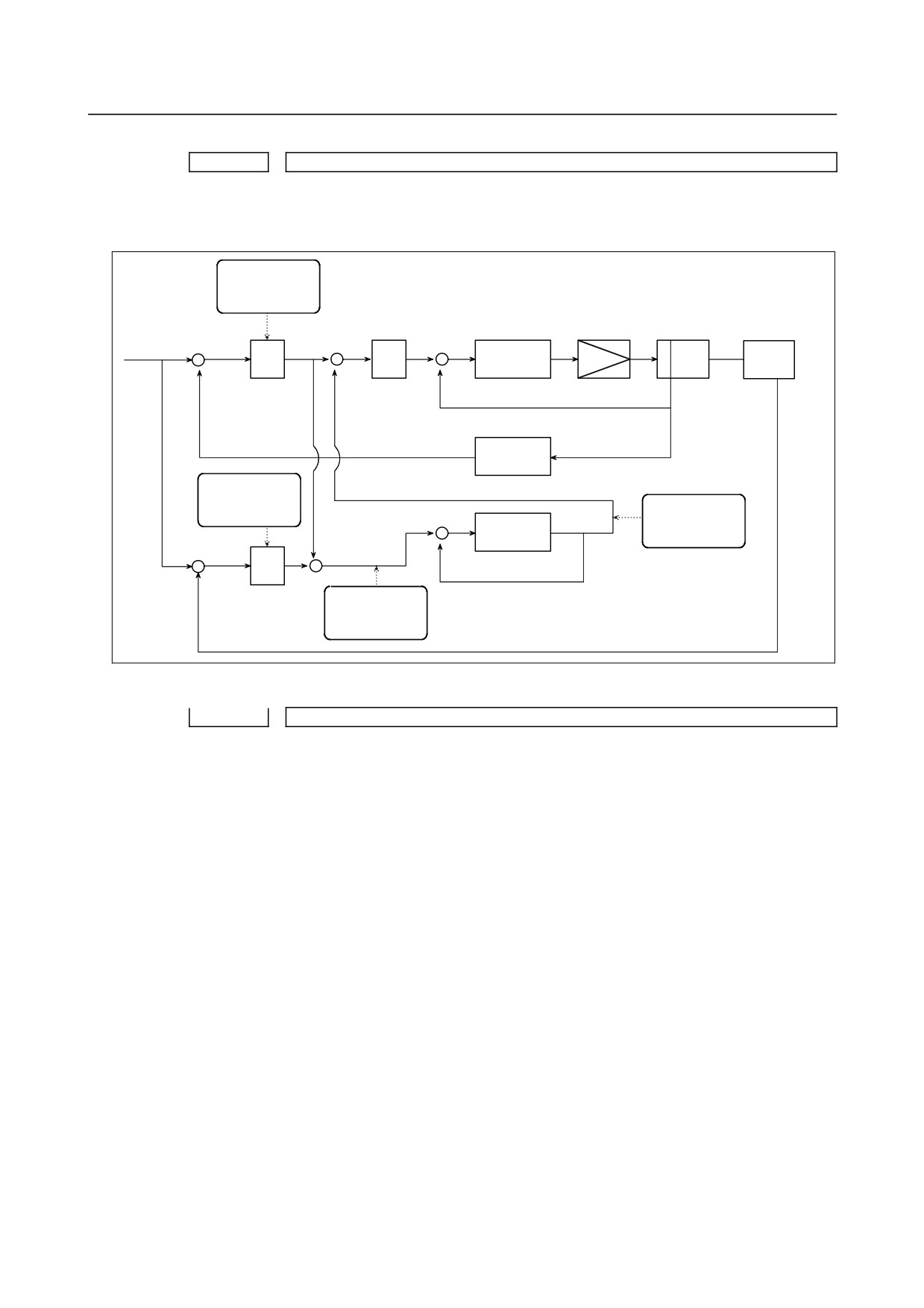
The data items displayed on the diagnosis screen are obtained at the following positions:
Semi-closed loop
error (No. 551)
Motor
Command +
+
Speed
+
Σ
Kp
Machine
control
-
+
-
Servo amplifier
Ps
Conversion
coefficients
Closed loop
(Parameters No. 2078 and 2079)
Amount of dual
error (No. 550)
position
+
× Time
compensation (No.
constant
553)
+
-
+
Σ
(Parameter No. 2080)
-
+
Error between
semi-closed and
closed loops (No.
552)
Automatic alteration of tool position compensation
Diagnosis
0560
Manual tool compensation state number
[Data type] Byte
[Unit of data] None
[Valid data range] 0 to 255
When incomplete operation was performed in manual tool compensation, one of the
following numbers is used for notification.
0 : Manual tool compensation was completed normally.
1 : The data of T code command falls outside the allowable range.
2 : The offset value falls outside the range.
3 : The offset number falls outside the range.
4 : Automatic operation or axis movement is being performed in the CNC.
5 : The CNC is in the tool-nose radius compensation mode.
6 : The CNC is in a mode other than the JOG mode, HNDL (INC) mode, and REF
mode.
7 : A CNC parameter is illegal.
8 : The CNC is in the 3-dimensional cutter compensation mode or tool center point
control mode.
- 31 -
1.DISPLAY AND OPERATION
B-64485EN/01
Data for adjusting the compensation of the start position of thread cutting when
the spindle speed is changed
Diagnosis
670
Delay in acceleration/deceleration after interpolation that is calculated in the NC
Diagnosis
671
Servo delay calculated in the NC
Diagnosis
672
Delay in one-rotation signal detection that is calculated in the NC
[Data type] 2-word path
[Unit of data] Metric input: 0.00001mm
Inch input : 0.000001inch
[Valid data range] 0 to 99,999,999
Compensation amounts calculated by the NC are indicated. Use them to set adjustment
parameters Nos. 1446 to 1449.
State of high-speed HRV current control
#7
#6
#5
#4
#3
#2
#1
#0
Diagnosis
700
DCLNK
HOK
HON
[Data type] Bit axis
The state of high-speed HRV current control is displayed.
#0 HON The motor is controlled in the high-speed HRV current control mode.
#1 HOK This bit is set to 1 when high-speed HRV current control is enabled.
High-speed HRV current control is enabled when the following conditions are satisfied:
• Bit 0 (HR3) of parameter No. 2013 is set to 1.
• Bit 0 (HR4) of parameter No. 2014 is set to 1.
• Servo software, servo modules, and servo amplifiers suitable for high-speed HRV
current control are used.
• When a separate detector interface unit is used, the separate detector interface unit is
suitable for high-speed HRV current control.
#2 DCLNK This bit is set to 1 when voltage information can be output to the diagnosis screen.
Thermal growth compensation along tool vector
Diagnosis
705
Thermal growth compensation amount for each axis
[Data type] Word axis
[Unit of data] Detection unit
[Valid data range] −32768 to +32767
The compensation amount for each axis in thermal growth compensation along the tool
vector is indicated.
Spindle error and warning states
Diagnosis
710
Spindle error state
[Data type] Word spindle
Diagnosis
712
Spindle warning state
[Data type] Word spindle
When an error (yellow LED ON + error number indication) or a warning occurs in a
Spindle Amplifier (SP), the number is indicated on the diagnosis screen.
If neither error nor warning occurs, 0 is indicated.
For spindle errors, refer to "FANUC SERVO MOTOR αi series Maintenance Manual"
(B-65285EN).
For warnings, see Subsection 10.1.4, "Spindle Warning Interface" in this manual.
- 32 -
B-64485EN/01
1.DISPLAY AND OPERATION
OVC level
Diagnosis
750
OVC level
[Data type] Word axis
[Unit of data] %
The proportion of soft thermal (OVC) in the alarm issuance level is indicated.
Linear inclination compensation function
Diagnosis
751
Each axis linear inclination compensation
[Data type] Word axis
[Unit of data] Detection unit
[Valid data range] -32768 to +32767
Compensation of linear inclination compensation for each axis is indicated.
DC link voltage information
Diagnosis
752
DC link voltage information
[Data type] Word axis
[Unit of data] Vrms
[Valid data range] 0 to 452 (200 Vrms input amplifier)
0 to 905 (400 Vrms input amplifier)
DC link voltage information is indicated.
Servo motor
Diagnosis
760
R phase current value
[Data type] Word axis
[Unit of data] Value 6554 is equivalent to the maximum amplifier current.
[Valid data range] -6554 to +6554
The actual R phase current value of the servo motor is indicated.
Diagnosis
761
Effective current value
[Data type] Word axis
[Unit of data] Value 8027 is equivalent to the maximum amplifier current.
[Valid data range] -8027 to +8027
The effective current value of the servo motor is indicated.
Diagnosis
762
Activating phase
[Data type] Word axis
[Unit of data] Value 256 is equivalent to 360 degrees.
[Valid data range] 0 to 255
The activating phase (electrical angle) of the servo motor is indicated.
Reason why a start cannot be performed
#7
#6
#5
#4
#3
#2
#1
#0
Diagnosis
1006
ALM
*SP
[Data type] Bit
The reason why a start cannot be performed is displayed.
#0
*SP The feed hold signal (*SP) is 0.
#1 ALM An alarm occurs.
Automatic data backup
#7
#6
#5
#4
#3
#2
#1
#0
Diagnosis
1016
ANG
ACM
DT3
DT2
DT1
AEX
[Data type] Bit
The execution state of backup is indicated.
#0 AEX Automatic data backup is being performed.
- 33 -
1.DISPLAY AND OPERATION
B-64485EN/01
#1 DT1 Data 1 was updated in the previous backup.
#2 DT2 Data 2 was updated in the previous backup.
#3 DT3 Data 3 was updated in the previous backup.
#6 ACM Automatic data backup was performed.
#7 ANG An error occurred in automatic data backup.
Fan rotation speed
Diagnosis
1002
FAN1 rotation speed
Diagnosis
1003
FAN2 rotation speed
Diagnosis
1490
FAN3 rotation speed
Diagnosis
1491
FAN4 rotation speed
[Data type] 2-word
[Unit of data] 1/min
FAN1, FAN2
The rotation speed of the fans in the CNC controller are indicated.
FAN3, FAN4
The rotation speed of the fans in the stand-alone CNC with 15" LCD display are
indicated.
If there is no applicable fan, 0 is indicated.
Custom macro / execution macro / auxiliary macro
Diagnosis
1493
Number of blocks in the macro statements executed by a custom macro/execution macro
[Data type] 2-word
[Unit of data] Block
Displays the number of blocks in the macro statements executed by a custom
macro/execution macro per 1024 ms.
It provides an indication of the actual processing speed of macro statements.
Diagnosis
1494
Number of blocks in executed by an auxiliary macro
[Data type] 2-word
[Unit of data] Block
Displays the number of blocks executed by an auxiliary macro per 1024 ms.
It provides an indication of the actual processing speed of auxiliary macros.
Spindle revolution number history function
Diagnosis
1520
Spindle total revolution number 1
Diagnosis
1521
Spindle total revolution number 2
[Data type] 2-word spindle
[Unit of data] 1000 min-1
[Valid data range] 0 to 999999999
The number of revolutions of the spindle is counted and the total number of revolutions is
indicated.
Built-in 3D interference check
1900
Built-in 3D interference check processing time
[Data type] Word
[Unit of data] msec
[Description] Displays the current processing time required for 3D interference check.
- 34 -
B-64485EN/01
1.DISPLAY AND OPERATION
1901
Additional width for Built-in 3D interference check
[Data type] Real
[Unit of data] mm, inch (machine unit)
[Description] Displays the current additional width to be considered for 3D interference check.
The display unit is the same as the unit set for the reference axis (parameter No. 1031).
Detector battery exhaustion
#7
#6
#5
#4
#3
#2
#1
#0
Diagnosis
3019
EXP
INP
ABP
[Data type] Bit axis
If a detector battery low alarm is issued, the cause can be checked.
#3 ABP The battery of the A/B phase is low.
#4 INP The battery of the serial pulse coder (built-in position detector) is low.
#5 EXP The battery of the separate detector of serial type is low.
Diagnosis data related to axis synchronous control
Diagnosis
3500
Synchronization error amount
[Data type] 2-word axis
[Unit of data] Detection unit
[Valid data range] −99999999 to +99999999
The difference in position (synchronization error amount) between the master axis and
slave axis is indicated. This data is indicated for the slave axis.
Diagnosis
3501
Synchronization error compensation value
[Data type] 2-word axis
[Unit of data] Detection unit
[Valid data range] −99999999 to +99999999
Cumulative value of compensation pulses (synchronization error compensation value)
output to the slave axis is indicated. This data is indicated for the slave axis.
Diagnosis data related to synchronous/composite control
Diagnosis
3502
Indication of synchronization error amount for each axis
[Data type] 2-word axis
[Unit of data] Detection unit
[Valid data range] −99999999 to +99999999
When synchronization deviation is detected (bit 1 (SERx) of parameter No. 8162 is set to
1), the positional deviation difference of the slave axis from the master axis is indicated.
The positional deviation difference is:
(Positional deviation of master axis) ± (positional deviation of slave axis)
↑
+when mirror image is applied to synchronization command
−when mirror image is not applied to synchronization command
Details of invalid FSSB setting alarms
Diagnosis
3510
FSSB alarm number
[Data type] Word
Information is output for identifying the location
(parameter) and cause of an
FSSB-related alarm which has been issued. For the displayed detail numbers and
corresponding causes and actions, see the table below. When multiple FSSB alarm
numbers appear, address the alarms in ascending order of the FSSB alarm number.
- 35 -

1.DISPLAY AND OPERATION
B-64485EN/01
Detail
Parameter
Cause
Action
alarm No.
number
120
The FSSB internal status did not
Check the connection between the CNC
451
-
change to open.
and each amplifier. Alternatively, the
452
servo card may be faulty.
The ATR value is inconsistent with the
Set the ATR value corresponding to the
140
24000 to 24095
connected slave (servo, spindle, or
connected slave.
450
separate detector).
The spindle amplifier number
Make the spindle amplifier number
3717
271
corresponding to the ATR value
consistent with the ATR value setting.
24000 to 24095
setting is not set.
The fifth to eighth separate detector is
Do not set the fifth to eighth separate
24000 to 24031
272
set for the first FSSB line (third FSSB
detectors for the first FSSB line (third
24064 to 24095
line).
FSSB line).
The first to fourth (ninth to twelfth)
Do not set the first to fourth (ninth to
273
24032 to 24063
separate detector is set for the second
twelfth) separate detectors for the
FSSB line.
second FSSB line.
The setting for a separate detector is
Make the setting for each separate
276
24000 to 24095
made more than once.
detector only once in the servo card.
The maximum number of slaves per
Reduce the number of slaves to 32
290
24000 to 24095
FSSB line is exceeded for an FSSB
(maximum number of slaves per FSSB
line of servo HRV2 control.
line of servo HRV2 control) or less.
The maximum number of slaves per
Reduce the number of slaves to 15
291
24000 to 24095
FSSB line is exceeded for an FSSB
(maximum number of slaves per FSSB
line of servo HRV3 control.
line of servo HRV3 control) or less.
The maximum number of slaves per
Reduce the number of slaves to 7
293
24000 to 24095
FSSB line is exceeded for an FSSB
(maximum number of slaves per FSSB
line of servo HRV4 control.
line of servo HRV4 control) or less.
The servo axis number corresponding
Set the value corresponding to the ATR
1023
to the ATR value setting of a separate
value setting for parameter No. 1023.
310
24104 to 24199
detector is not set for parameter No.
1023.
The servo axis number corresponding
Set the value corresponding to the ATR
1023
to the ATR value setting of a separate
value setting for parameter No. 1023.
313
14476#5
detector is not set for parameter No.
24104 to 24199
1023.
1023
The ATR value setting of a separate
Correct the settings of parameters Nos.
314
14476#5
detector is invalid.
24104 to 24199.
24104 to 24199
Manual setting 1 cannot be performed
Disconnect the separate detector.
383
-
when a separate detector is used.
Alternatively, perform manual setting or
automatic setting.
Servo initialization has not completed
An optical cable may be faulty or the
453
-
successfully.
connection between the amplifier and
another module may be incorrect.
Alarm No. 550 to 556 of diagnostic
Check diagnostic data No. 3511.
454
-
data No. 3511 occurred.
The ATR value of a spindle or
Set the ATR value corresponding to the
460
24000 to 24095
separate detector is set for a slave
connected slave.
which is not connected.
Although a separate detector is
Set the value for the separate detector in
471
24000 to 24095
connected, the separate detector
the corresponding parameter.
setting is not made.
In ATR value setting, a servo axis
Make settings so that any servo axis
480
24000 to 24095
number exceeds 80.
number does not exceed 80.
- 36 -

B-64485EN/01
1.DISPLAY AND OPERATION
Diagnosis
3511
FSSB alarm number
[Data type] Word axis
Information is output for identifying the location
(parameter) and cause of an
FSSB-related alarm which has been issued. For the displayed detail numbers and
corresponding causes and actions, see the table below. When multiple FSSB alarm
numbers appear, address the alarms in ascending order of the FSSB alarm number.
Detail
Parameter
Cause
Action
alarm No.
number
Although a separate detector is not
Set parameter Nos. 24096 to 24103 to
210
24096 to 24103
set, a value is set in parameter No.
all 0.
24096 to 24103.
An unavailable servo axis number is
Change the servo axis number.
220
1023
set.
A servo axis number is set more than
Change the servo axis number.
221
1023
once.
For a specific servo axis, two or more
To use two separate detectors for a
separate detectors are used and the
specific servo axis, one separate
paired separate detectors are two of
detector must have an odd number and
250
24096 to 24103
the first, third, fifth, and seventh units
the other must have an even number.
or the second, fourth, sixth, and eighth
Three or more separate detectors
units.
cannot be used.
・ The servo axis number
Check the conditions on the left.
corresponding to the ATR value
setting is not set for parameter No.
1023
1023.
270
24000 to 24095
・ An unavailable servo axis number is
set.
・ A servo axis number is set more
than once.
For an FSSB line of servo HRV3
For the FSSB line of servo HRV3
control, only the following servo axis
control, set the servo axis numbers on
1023
292
numbers can be used:
the left.
2013#0
(1 + 8n, 2 + 8n, 3 + 8n, 4 + 8n (n = 0,
1, …, 9))
For an FSSB line of servo HRV4
For the FSSB line of servo HRV4
1023
control, only the following servo axis
control, set the servo axis numbers on
294
2014#0
numbers can be used:
the left.
(1+8n(n=0,1,…,9))
311
24096 to 24103
A connector number is invalid.
Specify a value between 0 and 8.
A connector number is set more than
Make setting so that each connector
314
24096 to 24103
once.
number is used only once for one
separate detector.
2013#0
Different current loops (HRV) are
Set the same current loop (HRV) for the
350
2014#0
used for FSSB lines.
FSSB lines.
Different current loops (HRV) are set
Set servo axis numbers so that each set
1023
for the first and second FSSB lines
of (1 to 6), (9 to 14), (17 to 22), (25 to
360
2013#0
and parameter No. 1023 setting is
30), (33 to 38), and (41 to 46) is set for
2014#0
invalid.
the same FSSB line.
1902#0
When servo HRV3 or HRV4 control is
To set servo HRV3 or HRV4 control,
1902#1
set, manual setting 1 cannot be
perform manual setting or automatic
370
2013#0
performed.
setting.
2014#0
When a servo axis number is skipped,
Set servo axis numbers without skipping
380
1023
manual setting 1 cannot be
any number.
performed.
- 37 -
1.DISPLAY AND OPERATION
B-64485EN/01
Detail
Parameter
Cause
Action
alarm No.
number
An attempt was made to perform
Reduce the number of connected servo
manual setting 1 though the maximum
axes to the maximum number of
382
1023
number of controlled axes per FSSB
controlled axes or less.
line is exceeded.
470
24000 to 24095
An ATR value is set more than once.
Set each ATR value only once.
A servo axis number is inconsistent
Check whether the value set in
with the ATR value setting or the
parameter No. 1023 is consistent with
1023
481
servo motor having a servo axis
ATR value setting and whether the servo
24000 to 24095
number is not connected.
motor corresponding to each servo axis
number is connected.
At power-on, amplifier ID information
Check the connection between the CNC
520
2165
could not be read.
and each amplifier.
Alternatively, an amplifier may be faulty.
The ATR value setting is inconsistent
Make the value set in parameter No.
1023
550
with the servo axis number setting.
1023 consistent with the ATR value
24000 to 24095
setting.
The number of ATR value settings
Make as many settings as the number of
551
24000 to 24095
exceeds the number of slaves
slaves connected to the CNC.
connected to the CNC.
An unavailable servo axis number is
Change the servo axis number.
552
1023
set.
A servo axis number is set more than
Change the servo axis number.
553
1023
once.
A value is set in parameter No. 24096
Set parameters Nos. 24096 to 24103 to
554
24096 to 24103
to 24103 though no separate detector
all 0.
is connected.
555
The maximum current of an amplifier
Set the maximum current of the amplifier
557
2165
(parameter No. 2165) differs from that
(parameter No. 2165) to that of the
558
of a motor.
motor.
1023
1023
An invalid servo axis number is set.
Set a correct servo axis number.
Diagnosis
3513
FSSB alarm number
[Data type] Word spindle
Information is output for identifying the location
(parameter) and cause of an
FSSB-related alarm which has been issued.
For the displayed detail numbers and corresponding causes and actions, see the table
below. When multiple FSSB alarm numbers appear, address the alarms in ascending
order of the FSSB alarm number.
Detail
Parameter
Cause
Action
alarm No.
number
3717
An ATR value is set more than once.
Make each spindle amplifier consistent
271
24000 to 24095
with the ATR value setting.
When a spindle amplifier number is
Set spindle amplifier numbers without
381
3717
skipped, manual setting 1 cannot be
skipping any number.
performed.
Diagnosis data related to linear scale with absolute address reference marks
Diagnosis
3545
Linear scale with absolute address reference marks: Measurement point 1
Diagnosis
3546
Linear scale with absolute address reference marks: Measurement point 2
Diagnosis
3547
Linear scale with absolute address reference marks: Measurement point 3
- 38 -
B-64485EN/01
1.DISPLAY AND OPERATION
Diagnosis
3548
Linear scale with absolute address reference marks: Measurement point 4
[Data type] 2-word axis
[Unit of data] Detection unit
[Valid data range] -999999999 to 999999999
Diagnosis
3549
Linear scale with absolute address reference marks: Status display
Diagnosis
3550
Linear scale with absolute address reference marks: Scale value
[Data type] 2-word axis
[Unit of data] Detection unit
[Valid data range] -999999999 to 999999999
Diagnosis
3551
Linear scale with absolute address reference marks: Scale value (High)
[Data type] 2-word axis
[Unit of data] Detection unit
[Valid data range] -999 to 999
Linear scale with absolute address reference marks
Scale value = Diagnosis No.3551 × 1,000,000,000 + Diagnosis No.3550
Wrong operation prevention function
#7
#6
#5
#4
#3
#2
#1
#0
Diagnosis
3570
MSC
[Data type] Bit path
#0 MSC Memory operation is stopped due to the reconfirming of midway block start.
In a multipath system, the bit is set to 1 on only the path on which the cursor is position in
the middle of the program.
Diagnosis data related to flexible path axis assignment
Diagnosis
4000
Reason number of alarm in flexible path axis assignment
The cause of the alarm that may be issued in flexible path axis assignment is displayed.
1
The number of axes in the path is 0.
2
The number of axes in the path is larger than its allowable maximum value.
3
The removal command has no ID specification.
4
The removal command has a duplicate ID specification.
5
An axis specified with removal command P does not exist in the path or has been
removed from the path.
6
An axis specified with removal command Q does not exist in the path or has been
removed from the path.
7
An axis specified with removal command R does not exist in the path or has been
removed from the path.
8
An axis specified with the removal command does not exist in the path or has been
removed from the path.
9
The removal command has no axis specification or has an ID specification.
10
In flexible path axis assignment, the ID specification is incorrect.
11
The assignment command has no ID specification.
12
The assignment command has a duplicate ID specification.
13
The assignment command has a duplicate axis arrangement specification.
14
The path specified with the arrangement command has no target axis or the
arrangement command has no ID specification.
15 The path specified with the arrangement command has an invalid axis assignment
specification.
- 39 -
1.DISPLAY AND OPERATION
B-64485EN/01
16
An axis whose removal a command is waiting for belongs to the path where the
command was issued.
18
An axis whose removal an exchange command is waiting for belongs to the path
paired with the path where the exchange command was issued.
19
An axis for which an assignment command was issued is yet to be removed. (Bit 1
of parameter No. 11561 is set to 1.)
20
An axis for which an assignment command is issued in a path belongs to another
path where a removal command for it has been issued.
21
An axis for which an assignment command was issued is yet to be removed.
22
The assignment command has no axis specification or has an ID specification.
24
An axis at which an exchange command is targeted belongs to the path where the
exchange command was issued.
25
The exchange command has no ID specification.
26
The exchange command has a duplicate ID specification.
27
In a system having 3 or more paths, an exchange command has no L specification.
28
An axis targeted by an exchange command was not found in the source path (path
where this exchange command was issued).
29
An axis specified in the exchange command is being processed by another command
or has already been removed.
30
An axis targeted by an exchange command was not found in the destination path
(path paired with a path where another exchange command was issued for the axis).
32
The exchange command has no target axis.
33
The exchange command has a conflict.
34
The exchange command has no axis specification or has an ID specification.
35
A cycle other than flexible path axis assignment is under way.
36
An attempt was made to perform flexible path axis assignment during the SV
rotation control mode.
37
An attempt was made to perform flexible path axis assignment during the polygon
turning mode.
38
An attempt was made to perform flexible path axis assignment during PMC axis
control.
39
An attempt was made to perform flexible path axis assignment during the chopping
mode.
40
An attempt was made to perform flexible path axis assignment during mirror
imaging.
41
An attempt was made to perform flexible path axis assignment during 3-dimensional
coordinate conversion.
42
An attempt was made to perform flexible path axis assignment during coordinate
system rotation.
43
An attempt was made to perform flexible path axis assignment during scaling.
44
An attempt was made to perform flexible path axis assignment during axis
synchronization.
45
An attempt was made to perform flexible path axis assignment for an axis already
removed.
46
An attempt was made to perform flexible path axis assignment for an axis under
composite control.
47
An attempt was made to perform flexible path axis assignment for an axis under
synchronous control.
48
An attempt was made to perform flexible path axis assignment for an axis under
superimposed control.
55
An attempt was made to perform flexible path axis assignment simultaneously with
an axis move command.
56
An attempt was made to perform flexible path axis assignment during tool
compensation.
- 40 -
B-64485EN/01
1.DISPLAY AND OPERATION
Diagnosis
4001
Belonging path of axis in flexible path axis assignment
A path (specified by parameter No. 981) to which an axis specified for flexible path axis
assignment belongs is displayed.
0
: Source path
1 to 10
: Destination path (because of assignment or exchange)
-1 to -10
: Already removed
Pulse superimposed function
Diagnosis
4110
Number of accumulated pulses specified by the pulse superimposed function
[Data type] Floating point number axis
[Unit of data] Input unit
The number of accumulated pulses specified by pulse superimposition is indicated. The
number multiplied by the travel distance magnification is indicated.
Diagnosis
4110
Number of accumulated pulses specified by the pulse superimposed function
[Data type] Floating point number axis
[Unit of data] Input unit
When the maximum cutting feedrate is to be exceeded by the specified pulse
superimposition, the pulses exceeding the allowable number (set in parameter No. 7117)
are discarded.
This diagnosis data indicates the number of accumulated pulses that are actually
discarded in pulse superimposition.
| Number of pulses specified by pulse superimposition × travel distance magnification | >
|maximum cutting feedrate + allowable number of pulses |
→ Number of discarded pulses
= Number of pulses specified by pulse superimposition × travel distance magnification -
maximum cutting feedrate - allowable number of pulses
| Number of pulses specified by pulse superimposition × travel distance magnification | <
|maximum cutting feedrate + allowable number of pulses |
→ Number of discarded pulses = 0
NOTE
When the pulse superimposed function is disabled (bit 0 (PSI) of
parameter No. 10350 is set to 0), reset operation clears the
indicated number of accumulated/discarded pulses.
Total of the current actual power consumption of all servo axes/spindles
Diagnosis
4900
Total of current actual power consumption of all axes
[Data type] 2-word
[Unit of data] W
NOTE
The actual power consumption is obtained by subtracting the
regenerative power from the power consumption. If the
regenerative power exceeds the power consumption, the actual
power consumption becomes a negative value.
Current actual power consumption of each servo axis
Diagnosis
4901
Current actual power consumption of each servo axis
[Data type] 2-word axis
- 41 -