FANUC Series 30i-MODEL B, 31i-MODEL B, 32i-MODEL B. MAINTENANCE MANUAL - page 1
B-64485EN/01
SAFETY PRECAUTIONS
SAFETY PRECAUTIONS
This section describes the safety precautions related to the use of CNC units. It is essential that these
precautions be observed by users to ensure the safe operation of machines equipped with a CNC unit (all
descriptions in this section assume this configuration).
CNC maintenance involves various dangers. CNC maintenance must be undertaken only by a qualified
technician.
Users must also observe the safety precautions related to the machine, as described in the relevant manual
supplied by the machine tool builder.
Before checking the operation of the machine, take time to become familiar with the manuals provided by
the machine tool builder and FANUC.
Contents
DEFINITION OF WARNING, CAUTION, AND NOTE
s-1
WARNINGS RELATED TO CHECK OPERATION
s-2
WARNINGS RELATED TO REPLACEMENT
s-3
WARNINGS RELATED TO PARAMETERS
s-3
WARNINGS, CAUTIONS, AND NOTES RELATED TO DAILY MAINTENANCE
s-4
DEFINITION OF WARNING, CAUTION, AND NOTE
This manual includes safety precautions for protecting the maintenance personnel (herein referred to as
the user) and preventing damage to the machine. Precautions are classified into Warnings and Cautions
according to their bearing on safety. Also, supplementary information is described as a Note. Read the
Warning, Caution, and Note thoroughly before attempting to use the machine.
WARNING
Applied when there is a danger of the user being injured or when there is a
danger of both the user being injured and the equipment being damaged if the
approved procedure is not observed.
CAUTION
Applied when there is a danger of the equipment being damaged, if the
approved procedure is not observed.
NOTE
The Note is used to indicate supplementary information other than Warning and
Caution.
* Read this manual carefully, and store it in a safe place.
s-1

SAFETY PRECAUTIONS
B-64485EN/01
WARNINGS RELATED TO CHECK OPERATION
WARNING
1
When checking the operation of the machine with the cover removed
(1) The user's clothing could become caught in the spindle or other components,
thus presenting a danger of injury. When checking the operation, stand away
from the machine to ensure that your clothing does not become tangled in the
spindle or other components.
(2) When checking the operation, perform idle operation without workpiece.
When a workpiece is mounted in the machine, a malfunction could cause the
workpiece to be dropped or destroy the tool tip, possibly scattering fragments
throughout the area. This presents a serious danger of injury. Therefore,
stand in a safe location when checking the operation.
2
When checking the machine operation with the power magnetics cabinet door
opened
(1) The power magnetics cabinet has a high-voltage section (carrying a
mark). Never touch the high-voltage section. The high-voltage section
presents a severe risk of electric shock. Before starting any check of the
operation, confirm that the cover is mounted on the high-voltage section.
When the high-voltage section itself must be checked, note that touching a
terminal presents a severe danger of electric shock.
(2) Within the power magnetics cabinet, internal units present potentially
injurious corners and projections. Be careful when working inside the power
magnetics cabinet.
3
Never attempt to machine a workpiece without first checking the operation of the
machine. Before starting a production run, ensure that the machine is operating
correctly by performing a trial run using, for example, the single block, feedrate
override, or machine lock function or by operating the machine with neither a tool
nor workpiece mounted. Failure to confirm the correct operation of the machine
may result in the machine behaving unexpectedly, possibly causing damage to
the workpiece and/or machine itself, or injury to the user.
4
Before operating the machine, thoroughly check the entered data.
Operating the machine with incorrectly specified data may result in the machine
behaving unexpectedly, possibly causing damage to the workpiece and/or
machine itself, or injury to the user.
5
Ensure that the specified feedrate is appropriate for the intended operation.
Generally, for each machine, there is a maximum allowable feedrate. The
appropriate feedrate varies with the intended operation. Refer to the manual
provided with the machine to determine the maximum allowable feedrate. If a
machine is run at other than the correct speed, it may behave unexpectedly,
possibly causing damage to the workpiece and/or machine itself, or injury to the
user.
6
When using a tool compensation function, thoroughly check the direction and
amount of compensation. Operating the machine with incorrectly specified data
may result in the machine behaving unexpectedly, possibly causing damage to
the workpiece and/or machine itself, or injury to the user.
s-2
B-64485EN/01
SAFETY PRECAUTIONS
WARNINGS RELATED TO REPLACEMENT
WARNING
1
Before exchanging, be sure to shut off externally supplied power. Otherwise,
electrical shocks, breakdown, and blowout may occur.
If a control unit is turned off but other units are not, it is likely that power may be
supplied to servo units, resulting in the units being damaged and workers getting
an electrical shock when the units are exchanged.
2
In order to prevent damage that may be caused by static electricity, wear a
grounding wrist strap or take a similar protective measure before starting to
touch a printed-circuit board or unit or attach a cable.
Static electricity from human bodies can damage electrical circuits.
3
Voltage lingers in servo and spindle amplifiers for a while even after power has
been turned off, resulting in workers possibly getting an electrical shock when
the workers touch them. Before starting to exchange these amplifiers, wait for 20
minutes after power has been turned off.
4
When replacing a unit, ensure that the new unit has the same parameters and
settings as the old one. (For details, refer to the manual for the machine.)
Otherwise, unpredictable machine movement could damage the workpiece or
the machine itself or cause injury.
5
If you notice an apparent hardware fault, such as abnormal noise, abnormal
odor, smoke, ignition, or abnormal heat, in the hardware while power is being
supplied to it, shut it off at once. These faults can cause fire, breakdown,
blowout, and malfunction.
6
The radiating fins of control units, servo amplifiers, spindle amplifiers, and other
devices can remain very hot for a while after power has been turned off, making
you get burned if you touch them. Before starting to work on them, wait and
make sure they are cool.
7
When exchanging heavy stuff, you should do so together with two or more
people.
If the replacement is attempted by only one person, the old or new unit could slip
and fall, possibly causing injury.
8
Be careful not to damage cables. Otherwise, electrical shocks can occur.
9
When working, wear suitable clothes with safety taken into account. Otherwise,
injury and electrical shocks can occur.
10 Do not work with your hands wet. Otherwise, electrical shocks and damage to
electrical circuits can occur.
WARNINGS RELATED TO PARAMETERS
WARNING
1 When machining a workpiece for the first time after modifying a parameter, close
the machine cover. Never use the automatic operation function immediately after
such a modification. Instead, confirm normal machine operation by using
functions such as the single block function, feedrate override function, and
machine lock function, or by operating the machine without mounting a tool and
workpiece. If the machine is used before confirming that it operates normally, the
machine may move unpredictably, possibly damaging the machine or workpiece,
and presenting a risk of injury.
s-3
SAFETY PRECAUTIONS
B-64485EN/01
WARNING
2 The CNC and PMC parameters are set to their optimal values, so that those
parameters usually need not be modified. When a parameter must be modified
for some reason, ensure that you fully understand the function of that parameter
before attempting to modify it. If a parameter is set incorrectly, the machine may
move unpredictably, possibly damaging the machine or workpiece, and
presenting a risk of injury.
WARNINGS, CAUTIONS, AND NOTES RELATED TO DAILY
MAINTENANCE
WARNING
When using the controller unit, display unit, MDI unit, or machine operator's
panel, prevent these units from directly exposing to chips or coolants. Even if
direct exposure to coolants is prevented, coolants containing sulfur or chlorine at
a high activation level, oil-free synthetic-type coolants, or water-soluble coolants
at a high alkali level particularly have large effects on the control unit and
peripheral units, possibly causing the following failures.
• Coolants containing sulfur or chlorine at a high activation level
Some coolants containing sulfur or chlorine are at an extremely high activity
level. If such a coolant adheres to the CNC or peripheral units, it reacts
chemically with a material, such as resin, of equipment, possibly leading to
corrosion or deterioration. If it gets in the CNC or peripheral units, it corrodes
metals, such as copper and silver, used as component materials, possibly
leading to a defective component.
• Synthetic-type coolants having a high permeability
Some synthetic-type coolants whose lubricating component is, for example,
PAG (polyalkylene glycol) have an extremely high permeability. If such a
coolant is used even in equipment having a high closeness, it can readily flow
into the CNC or peripheral units through, for example, gaskets. It is likely that,
if the coolant gets in the CNC or a peripheral unit, it may deteriorate the
insulation and damage the components.
• Water-soluble coolants at a high alkali level
Some coolants whose pH is increased using alkanolamine are so strong
alkali that its standard dilution will lead to pH10 or higher. If such a coolant
spatters over the surface of the CNC or peripheral unit, it reacts chemically
with a material, such as resin, possibly leading to corrosion or deterioration.
WARNING
Battery replacement
Do not replace batteries unless you have been well informed of maintenance
work and safety.
When opening the cabinet and replacing batteries, be careful not to touch any
high-voltage circuit (marked with
and covered with an electric shock
prevention cover).
When the electric shock prevention cover has been removed, you will get an
electric shock if you touch any high-voltage circuit.
s-4
B-64485EN/01
SAFETY PRECAUTIONS
WARNING
Fuse replacement
Before replacing a blown fuse, it is necessary to remove the cause of the blown
fuse.
So, do not replace fuses unless you have been well informed of maintenance
work and safety.
When opening the cabinet and replacing fuses, be careful not to touch any
high-voltage circuit (marked with
and covered with an electric shock
prevention cover).
When the electric shock prevention cover has been removed, you will get an
electric shock if you touch any high-voltage circuit.
CAUTION
Handle the batteries gently. Do not drop them or give a strong impact to them.
NOTE
Each control unit uses batteries, because it must hold data, such as programs,
offset values, and parameters even when AC power for it is off.
Back up the data (programs, offset values, and parameters) regularly.
If the battery voltage becomes low, a low battery voltage alarm is displayed on
the machine operator’s panel or screen.
Once the battery voltage alarm has been displayed, replace the batteries within
one week. Otherwise, the memory contents may be lost. The time when the
battery for the absolute pulse coder is to be replaced depends on the machine
configuration including the detector type. For details, contact the machine tool
builder.
For the battery replacement procedure, see Chapter 3 or 4. Recollect or discard
old batteries in the way your local autonomous community specifies.
s-5

B-64485EN/01
PREFACE
PREFACE
The manual consists of the following chapters:
Description of this manual
1.
DISPLAY AND OPERATION
This chapter covers those items, displayed on the screen, that are related to maintenance. A list of all
supported operations is also provided at the end of this chapter.
2.
CONTROL UNIT HARDWARE
This chapter describes the hardware configuration, printed circuit boards and their mounting
positions, and LED display and installation of the control unit.
3.
REPLACING CONTROL UNIT MAINTENANCE PARTS
This chapter describes the replacement of maintenance parts of the control unit.
4.
MAINTENANCE OF THE OTHER UNITS
This chapter describes the basics of maintenance of other units.
5.
INPUT AND OUTPUT OF DATA
This chapter describes the input/output of data, including programs, parameters, and tool
compensation data, as well as the input/output procedures for conversational data.
6.
INTERFACE BETWEEN CNC AND PMC
This chapter describes the PMC specifications, the system configuration, and the signals used by the
PMC.
7.
EMBEDDED ETHERNET FUNCTION
This chapter describes the embedded Ethernet.
8.
DIGITAL SERVO
This chapter describes the servo tuning screen and how to adjust the reference position return
position.
9.
AC SPINDLE
This chapter describes the spindle tuning screen.
10.
TROUBLESHOOTING
This chapter describes the procedures to be followed in the event of certain problems occurring, for
example, if the power cannot be turned on or if manual operation cannot be performed.
Countermeasures to be applied in the event of alarms being output are also described.
11.
MOTOR/DETECTOR/AMPLIFIER PREVENTIVE MAINTENANCE
This chapter describes the basic information about the preventive maintenance of motors, detectors,
and amplifiers.
APPENDIX
A. ALARM LIST
B. LIST OF MAINTENANCE PARTS
C. BOOT SYSTEM
D. MEMRY CARD SLOT
E. LED DISPLAY
F. MAINTENANCE OF PERSONAL COMPUTER FUNCTIONS (BOOT-UP AND IPL)
G. MAINTENANCE OF STAND-ALONE TYPE UNIT
H. ETHERNET DISPLAY FUNCTION
J.
MEMORY CLEAR
K.
USB FUNCTION MAINTENANCE
This manual does not provide a parameter list. If necessary, refer to the separate PARAMETER
MANUAL.
p-1
PREFACE
B-64485EN/01
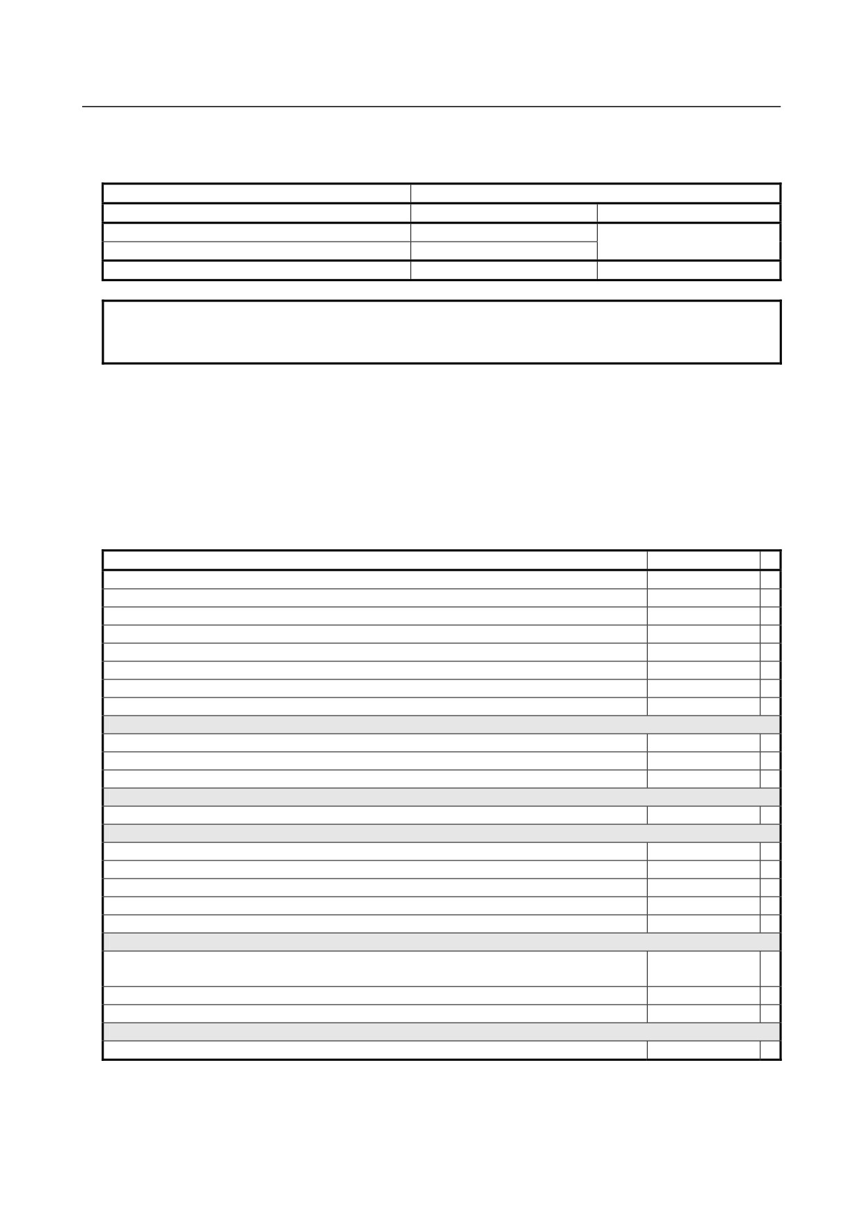
Applicable models
This manual can be used with the following models. The abbreviated names may be used.
Model name
Abbreviation
FANUC Series 30i-B
30i -B
Series 30i
FANUC Series 31i-B5
31i -B5
Series 31i
FANUC Series 31i-B
31i -B
FANUC Series 32i-B
32i -B
Series 32i
NOTE
Some function described in this manual may not be applied to some products.
For details, refer to the DESCRIPTIONS manual (B-64482EN).
Related manuals of
Series 30i- MODEL B
Series 31i- MODEL B
Series 32i- MODEL B
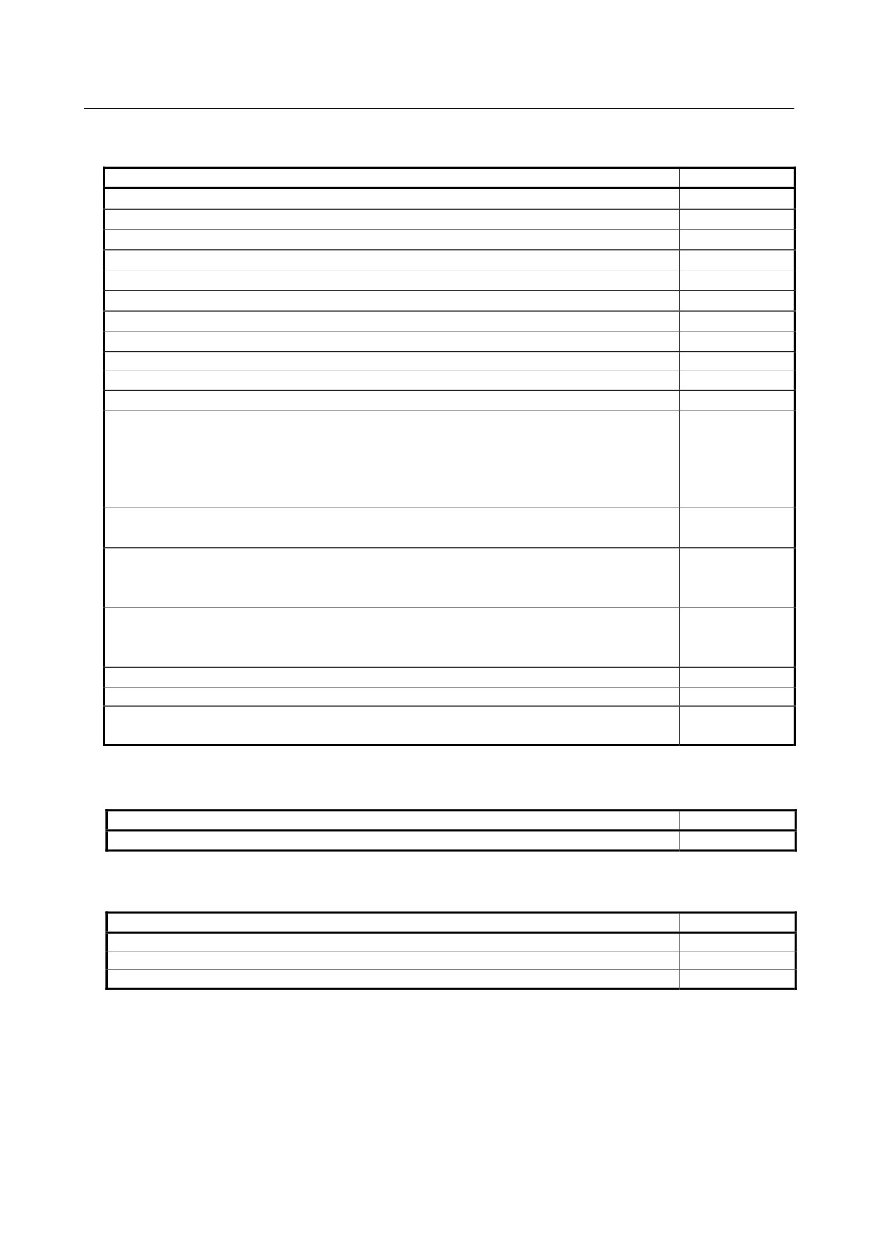
The following table lists the manuals related to Series 30i-B, Series 31i-B, Series 32i-B. This manual is
indicated by an asterisk(*).
Table 1 Related manuals
Manual name
Specification
DESCRIPTIONS
B-64482EN
CONNECTION MANUAL (HARDWARE)
B-64483EN
CONNECTION MANUAL (FUNCTION)
B-64483EN-1
OPERATOR’S MANUAL (Common to Lathe System/Machining Center System)
B-64484EN
OPERATOR’S MANUAL (For Lathe System)
B-64484EN-1
OPERATOR’S MANUAL (For Machining Center System)
B-64484EN-2
MAINTENANCE MANUAL
B-64485EN
*
PARAMETER MANUAL
B-64490EN
Programming
Macro Executor PROGRAMMING MANUAL
B-63943EN-2
Macro Compiler PROGRAMMING MANUAL
B-66263EN
C Language Executor PROGRAMMING MANUAL
B-63943EN-3
PMC
PMC PROGRAMMING MANUAL
B-64513EN
Network
PROFIBUS-DP Board CONNECTION MANUAL
B-63993EN
Fast Ethernet / Fast Data Server OPERATOR’S MANUAL
B-64014EN
DeviceNet Board CONNECTION MANUAL
B-64043EN
FL-net Board CONNECTION MANUAL
B-64163EN
CC-Link Board CONNECTION MANUAL
B-64463EN
Operation guidance function
MANUAL GUIDE i (Common to Lathe System/Machining Center System) OPERATOR’S
B-63874EN
MANUAL
MANUAL GUIDE i (For Machining Center System) OPERATOR’S MANUAL
B-63874EN-2
MANUAL GUIDE i (Set-up Guidance Functions) OPERATOR’S MANUAL
B-63874EN-1
Dual Check Safety
Dual Check Safety CONNECTION MANUAL
B-64483EN-2
p-2
B-64485EN/01
PREFACE
Related manuals of SERVO MOTOR series
The following table lists the manuals related to SERVO MOTOR series
Manual name
Specification
FANUC AC SERVO MOTOR Įi series DESCRIPTIONS
B-65262EN
FANUC AC SERVO MOTOR ȕis series DESCRIPTIONS
B-65302EN
FANUC SYNCHROUNOUS BUILT-IN SERVO MOTOR DiS series DESCRIPTIONS
B-65332EN
FANUC LINEAR MOTOR LiS series DESCRIPTIONS
B-65382EN
FANUC AC SPINDLE MOTOR Įi series DESCRIPTIONS
B-65272EN
FANUC AC SPINDLE MOTOR ȕi series DESCRIPTIONS
B-65312EN
FANUC BUILT-IN SPINDLE MOTOR BiI series DESCRIPTIONS
B-65292EN
FANUC SYNCHROUNOUS BUILT-IN SPINDLE MOTOR BiS series DESCRIPTIONS
B-65342EN
FANUC - NSK SPINDLE UNIT series DESCRIPTIONS
B-65352EN
FANUC SERVO AMPLIFIER Įi series DESCRIPTIONS
B-65282EN
FANUC SERVO AMPLIFIER ȕi series DESCRIPTIONS
B-65322EN
FANUC AC SERVO MOTOR Įi series
FANUC AC SERVO MOTOR ȕi series
FANUC LINEAR MOTOR LiS series
B-65270EN
FANUC SYNCHRONOUS BUILT-IN SERVO MOTOR DiS series
PARAMETER MANUAL
FANUC AC SPINDLE MOTOR Įi/ȕi series
B-65280EN
BUILT-IN SPINDLE MOTOR Bi series PARAMETER MANUAL
FANUC AC SERVO MOTOR Įis/Įi series
AC SPINDLE MOTOR Įi series
B-65285EN
SERVO AMPLIFIER Įi series MAINTENANCE MANUAL
FANUC AC SERVO MOTOR ȕis series
AC SPINDLE MOTOR ȕi series
B-65325EN
SERVO AMPLIFIER ȕi series MAINTENANCE MANUAL
FANUC SERVO AMPLIFIER ȕi series MAINTENANCE MANUAL
B-65395EN
FANUC SERVO GUIDE OPERATOR’S MANUAL
B-65404EN
FANUC AC SERVO MOTOR Įis/Įi/ȕis series
B-65264EN
SERVO TUNING PROCEDURE (BASIC)
Related manuals of FANUC PANEL i
The following table lists the manuals related to FANUC PANEL i.
Manual name
Specification
FANUC PANEL i CONNECTION AND MAINTENANCE MANUAL
B-64223EN
Related manuals of FANUC I/O Unit
The following table lists the manuals related to FANUC I/O Unit.
Manual name
Specification
FANUC I/O Unit-MODEL A CONNECTION AND MAINTENANCE MANUAL
B-61813E
FANUC I/O Unit-MODEL B CONNECTION AND MAINTENANCE MANUAL
B-62163E
Handy Machine Operator’s Panel CONNECTION MANUAL
B-63753EN
Training
• FANUC runs FANUC Training Center to train those who will
be
involved in the connection,
maintenance, and operation of FANUC products. It is recommended to attend the class so you will
be able to use the products effectively.
Visit the following web site for detailed descriptions of its curriculum.
p-3

B-64485EN/01
TABLE OF CONTENTS
TABLE OF CONTENTS
SAFETY PRECAUTIONS
s-1
DEFINITION OF WARNING, CAUTION, AND NOTE
s-1
WARNINGS RELATED TO CHECK OPERATION
s-2
WARNINGS RELATED TO REPLACEMENT
s-3
WARNINGS RELATED TO PARAMETERS
s-3
WARNINGS, CAUTIONS, AND NOTES RELATED TO DAILY MAINTENANCE
s-4
PREFACE
p-1
1
DISPLAY AND OPERATION
1
1.1
FUNCTION KEYS AND SOFT KEYS
1
1.1.1
Soft Key Structure
1
1.1.2
General Screen Operations
1
1.1.3
Function Keys
2
1.1.4
Soft Keys
3
1.2
SYSTEM CONFIGURATION SCREEN
9
1.2.1
Display Method
9
1.2.2
Hardware Configuration Screen
10
1.2.3
Software Configuration Screen
11
1.2.4
Outputting System Configuration Data
13
1.3
DIAGNOSIS FUNCTION
13
1.3.1
Displaying Diagnosis Screen
13
1.3.2
Contents Displayed
13
1.4
CNC STATE DISPLAY
44
1.5
OPERATING MONITOR
46
1.5.1
Display Method
46
1.5.2
Parameters
47
1.6
WAVEFORM DIAGNOSIS DISPLAY
48
1.6.1
Waveform Diagnosis Graph Screen
48
1.6.2
Waveform Diagnosis Parameter Screen
49
1.6.3
Tracing Data
58
1.6.4
Outputting Data
59
1.7
COLOR SETTING SCREEN
65
1.7.1
Screen Display
65
1.7.2
Operations for Color Setting
65
1.7.3
Parameter
66
1.7.4
Notes
68
1.8
POWER MATE CNC MANAGER FUNCTION
68
1.8.1
Screen Display
69
1.8.2
Inputting and Outputting Parameters
73
1.8.3
Parameters
74
1.8.4
Notes
76
1.9
SERVO GUIDE MATE
77
1.9.1
Wave Display
77
1.9.1.1
Y-time graph
78
1.9.1.2
XY graph
95
1.9.1.3
Circle graph
105
1.9.1.4
Fourier graph
114
1.9.1.5
Bode graph
120
c-1
TABLE OF CONTENTS
B-64485EN/01
1.9.1.6
Parameters
129
1.10
MAINTENANCE INFORMATION SCREEN
131
1.10.1 Displaying the Maintenance Information Screen
131
1.10.2 Operating the Maintenance Information Screen
132
1.10.3 Half-Size Kana Input on the Maintenance Information Screen
133
1.10.4 Warnings That Occurs on the Maintenance Information Screen
134
1.10.5 Parameter
134
1.10.6 Overview of the History Function
135
1.10.6.1 Alarm history
136
1.10.6.2 External operator message history
138
1.10.6.3 Operation history
142
1.10.6.4 Operation history signal selection
148
1.10.6.5 Outputting all history data
153
1.11
SYSTEM ALARM HISTORY SCREEN
156
1.11.1 System Alarm History List Screen
156
1.11.2 System Alarm History Detail Screen
157
1.11.3 Outputting System Alarm History
158
1.11.4 Parameter
158
2
CONTROL UNIT HARDWARE
159
2.1
EXAMPLE OF HARDWARE CONFIGURATION
159
2.1.1
Example of the Hardware Configuration of the LCD-mounted Type Control
Unit
159
2.1.2
Example of the Hardware Configuration of the Stand-alone Type Control Unit.160
2.2
HARDWARE OVERVIEW
161
2.2.1
LCD-mounted Type Control Unit Overview
161
2.2.2
Stand-alone Type Control Unit Overview
162
2.3
TOTAL CONNECTION DIAGRAMS
163
2.3.1
Control Unit Connection Diagram
163
2.3.2
Connection Diagram of a Display Unit for the Stand-Alone Type Control Unit.167
2.4
HARDWARE OF LCD-MOUNTED TYPE CONTROL UNIT
171
2.4.1
LCD-mounted Type Control Unit (8.4” LCD Unit and 10.4” LCD Unit A)
171
2.4.2
LCD-mounted Type Control Unit (10.4” LCD Unit B and 15” LCD Unit)
180
2.4.3
LCD-mounted Type Control Unit (with Personal Computer Function with
Windows®CE) Hardware
188
2.5
HARDWARE OF STAND-ALONE TYPE CONTROL UNIT
198
2.5.1
Stand-alone Type Control Unit
198
2.5.2
Display Unit for Stand-alone Type Control Unit
203
2.5.2.1
Display Unit (10.4” LCD unit A)
203
2.5.2.2
Display unit (10.4” LCD unit B and 15” LCD unit)
206
2.5.2.3
Display unit for automotive manufacture
211
2.5.3
Display Unit for Stand-Alone Type Control Unit (with Personal Computer
Function with Windows®CE)
219
2.6
HARDWARE OF OPTIONAL BOARDS
226
2.6.1
Fast Ethernet Board
226
2.6.2
Additional axis board
228
2.6.3
HSSB interface board
229
2.6.4
PROFIBUS-DP Board
230
2.6.5
DeviceNet Board
233
2.6.6
CC-Link Board
239
2.7
ENVIRONMENTAL REQUIREMENTS OUTSIDE THE CABINET
241
2.7.1
Environmental Conditions outside the Cabinet
241
2.7.2
Installation Conditions of the Control Unit
241
2.8
CAUTIONS RELATED TO GROUNDING AND NOISE
242
c-2
B-64485EN/01
TABLE OF CONTENTS
2.8.1
Separating Cables
242
2.8.2
Noise Suppressor
244
2.8.3
Cable Clamp and Shield Processing
245
2.8.4
Lightning Surge Absorber
247
3
REPLACING CONTROL UNIT MAINTENANCE PARTS
249
3.1
CAUTIONS FOR REPLACEMENT
249
3.1.1
Optional Information File
250
3.1.2
Attaching and Detaching Units
250
3.1.3
Tightening Torque for Fastening Units and Ground Terminals
251
3.1.4
Packing
251
3.2
REPLACING THE MAIN BOARD
253
3.2.1
LCD-mounted Type Control Unit
253
3.2.2
Stand-alone Type Control Unit
255
3.3
REPLACING THE DISPLAY CONTROL BOARD FOR THE DISPLAY
UNIT
256
3.4
REPLACING LCD UNITS
257
3.4.1
LCD-mounted Type Control Unit (8.4” LCD Unit and 10.4” LCD Unit)
257
3.4.2
Display Unit for Stand-alone Type Control Unit (10.4” LCD Unit)
258
3.5
MOUNTING AND DEMOUNTING CARD PCBS
259
3.6
MOUNTING AND DEMOUNTING FROM/SRAM MODULE
261
3.7
ATTACHING A COMPACT FLASH CARD ONTO, AND DETACHING IT
FROM, A PRINTED CIRCUIT BOARD
262
3.8
INSERTING AND EXTRACTING OPTIONAL BOARDS
263
3.9
REPLACING FUSES
265
3.9.1
LCD-mounted Type Control Unit
266
3.9.2
LCD-mounted Type Control Unit (Personal Computer Function with
Windows® CE)
267
3.9.3
Stand-alone Type Control Unit
267
3.9.4
Display Unit for Stand-alone Type Control Unit
268
3.9.4.1
Display unit (10.4” LCD unit A)
268
3.9.4.2
Display unit (10.4” LCD unit B and 15” LCD unit)
268
3.9.4.3
Display unit for Automotive manufacture
269
3.9.5
Replacing the Fuse on the Display Unit for the Stand-Alone Type Control Unit
(with PC Functions Supporting Windows® CE)
269
3.10
REPLACING THE MEMORY BACKUP BATTERY IN THE CONTROL
UNIT
270
3.10.1 Replacing a Lithium Battery
270
3.10.2 Replacing a Commercial D-size Alkaline Dry Cells
273
3.11
REPLACING A FAN
274
3.11.1 LCD-mounted Type Control Unit
274
3.11.2 Stand-alone Type Control Unit
275
3.11.3 Display Unit for Automotive
276
3.11.4 Display Unit for Stand-alone Type Control Unit (Personal Computer Function
with Windows® CE)
277
3.12
REPLACING THE PROTECTION COVER
278
3.13
REPLACING THE TOUCH PANEL PROTECTION SHEET
279
3.14
TOUCH PANEL CALIBRATION
280
3.15
REPLACING THE BACKUP UNIT
284
4
MAINTENANCE OF THE OTHER UNITS
285
4.1
CAUTIONS COMMON TO THE OTHER UNITS
285
c-3
TABLE OF CONTENTS
B-64485EN/01
4.2
UNITS SUPPORTING I/O Link i
285
4.2.1
Items Common to Units Supporting I/O Link i
285
4.2.2
I/O Module for Connector Panel [Supporting I/O Link i]
286
4.2.3
I/O Module for Operator’s Panel (Supporting Matrix Input)
[Supporting I/O Link i]
289
4.2.4
Connection of I/O Module for Operator's Panel and I/O Module for Power
Magnetics Cabinet [Supporting I/O Link i]
290
4.2.5
I/O Module Type-2 for Connector Panel [Supporting I/O Link i]
291
4.2.6
Terminal Type I/O Module [Supporting I/O Link i]
293
4.2.7
I/O Link Connection Unit [Supporting I/O Link i]
298
4.2.8
Standard Machine Operator's Panel [Supporting I/O Link i]
300
4.3
UNITS SUPPORTING I/O Link
302
4.3.1
I/O Link-AS-i Converter
302
4.4
SEPARATE DETECTOR INTERFACE UNIT
310
4.5
Analog Input Separate Detector Interface Unit
311
4.6
PANEL i
312
4.6.1
Replacing the Battery
312
4.6.2
Replacing the Fan
314
4.6.2.1
Replacing the fan in the PANEL i
314
4.6.2.2
Replacing the fan for the HDD
315
4.6.3
Replacing the Touch Panel Protection Sheet
315
4.7
REPLACING BATTERY FOR ABSOLUTE PULSECODERS
316
4.7.1
Overview
316
4.7.2
Replacing Batteries
316
4.7.3
Replacing the Batteries in a Separate Battery Case
317
4.7.4
Replacing the Battery Built into the Servo Amplifier
317
5
INPUT AND OUTPUT OF DATA
319
5.1
SETTING PARAMETERS FOR INPUT/OUTPUT
319
5.2
INPUTTING/ OUTPUTTING DATA
320
5.2.1
Confirming the Parameters Required for Data Output
321
5.2.2
Outputting CNC Parameters
322
5.2.3
Outputting Pitch Error Compensation Amount
323
5.2.4
Outputting Custom Macro Variable Values
323
5.2.5
Outputting Tool Compensation Amount
323
5.2.6
Outputting Part Program
323
5.2.7
Inputting CNC Parameters
324
5.2.8
Inputting Pitch Error Compensation Amount
325
5.2.9
Inputting Custom Macro Variable Values
326
5.2.10
Inputting Tool Compensation Amount
326
5.2.11
Inputting Part Programs
326
5.3
AUTOMATIC DATA BACKUP
327
6
INTERFACE BETWEEN CNC AND PMC
332
6.1
WHAT IS PMC?
332
6.1.1
Basic Configuration of PMC
332
6.1.2
I/O Signals of PMC
332
6.1.3
PMC Signal Addresses
333
6.1.4
Communication Method for External I/O Device
335
6.2
MULTI-PMC FUNCTION
336
6.2.1
Execution Order and Execution Time Percentage
337
6.2.2
Setting I/O Address for I/O Link i and I/O Link
338
6.2.3
Interface Between CNC and PMC
339
c-4
B-64485EN/01
TABLE OF CONTENTS
6.2.4
Multi-Path PMC Interface
340
6.2.5
System Relay Addresses (R9000, Z0)
341
6.3
PMC SPECIFICATIONS
346
6.3.1
Basic Specifications
346
6.3.2
Addresses
350
6.4
OPERATING THE PMC SCREEN
352
6.4.1
Transition of the PMC Screens
354
6.5
PMC DIAGNOSIS AND MAINTENANCE SCREENS ([PMC MAINTE])
355
6.5.1
Monitoring PMC Signal Status ([STATUS] Screen)
355
6.5.2
Checking PMC Alarms ([PMC ALARM] Screen)
356
6.5.3
Setting and Displaying Variable Timers ([TIMER] Screen)
357
6.5.4
Setting and Displaying Counter Values ([COUNTR] Screen)
359
6.5.5
Setting and Displaying Keep Relays ([KEEP RELAY] Screen)
360
6.5.6
Setting and Displaying Data Tables ([DATA] Screen)
361
6.5.7
Data Input/Output ([I/O] Screen)
367
6.5.8
Displaying i/o devices connection status ([I/O DEVICE] screen)
370
6.5.9
Signal Trace Function ([TRACE] Screen)
372
6.5.10
Setting of Trace Parameter ([TRACE SETING] Screen)
373
6.5.11
Execution of Trace
376
6.5.11.1 Operation after execution of trace
377
6.5.11.2 Automatic start of trace setting
380
6.5.12 MONITORING I/O DIAGNOSIS ([I/O DGN] SCREEN)
380
6.6
LADDER DIAGRAM MONITOR AND EDITOR SCREENS
([PMC LADDER])
384
6.6.1
Displaying a Program List ([LIST] Screen)
385
6.6.2
Monitoring Ladder Diagrams ([LADDER] Screen)
386
6.6.3
Editing Ladder Programs
389
6.6.3.1
NET EDITOR screen
391
6.6.4
PROGRAM LIST EDITOR Screen
393
6.6.5
Collective Monitor Function
394
6.6.5.1
COLLECTIVE MONITOR function
395
6.7
LIST OF ADDRESSES
398
7
EMBEDDED ETHERNET FUNCTION
435
7.1
EMBEDDED ETHERNET PORT AND PCMCIA ETHERNET CARD
435
7.2
SETTING UP THE EMBEDDED ETHERNET FUNCTION
437
7.2.1
Setting of the FOCAS2/Ethernet Function
437
7.2.1.1
Operation on the FOCAS2/Ethernet setting screen
438
7.2.1.2
Example of setting the FOCAS2/Ethernet function
440
7.2.2
Setting of the FTP File Transfer Function
440
7.2.2.1
Operation on the FTP file transfer setting screen
441
7.2.2.2
Related NC parameters
443
7.2.2.3
Example of setting the FTP file transfer function
443
7.2.3
Setting Up the DNS/DHCP Function
444
7.2.3.1
Setting up DNS
444
7.2.3.2
Setting up DHCP
445
7.2.3.3
Related NC parameters
447
7.2.4
Setting of the Unsolicited Messaging Function
448
7.2.4.1
Overview
448
7.2.4.2
Setting of the FOCAS2/Ethernet function
449
7.2.4.3
Mode selection
452
7.2.4.4
Setting on the CNC screen
454
7.2.4.5
Setting on the personal computer
457
7.2.4.6
Execution methods
457
c-5
TABLE OF CONTENTS
B-64485EN/01
7.2.4.7
Related NC parameters
463
7.2.5
Backing Up and Restoring Communication Parameters
464
7.3
SWITCHING BETWEEN THE EMBEDDED ETHERNET DEVICES
466
7.4
EMBEDDED ETHERNET OPERATIONS
466
7.4.1
FTP File Transfer Function
466
7.4.1.1
Displaying and operating the file list
469
7.5
RESTART OF THE EMBEDDED ETHERNET
470
7.6
MAINTENANCE SCREEN FOR EMBEDDED ETHERNET FUNCTION ... 471
7.7
LOG SCREEN OF THE EMBEDDED ETHERNET FUNCTION
474
8
DIGITAL SERVO
479
8.1
INITIAL SETTING SERVO PARAMETERS
479
8.2
FSSB SETTING SCREEN
489
8.3
SERVO TUNING SCREEN
501
8.3.1
Parameter Setting
501
8.3.2
Displaying Servo Tuning Screen
501
8.4
ADJUSTING REFERENCE POSITION (DOG METHOD)
502
8.5
DOGLESS REFERENCE POSITION SETTING
505
8.6
αi SERVO WARNING INTERFACE
506
8.7
αi SERVO INFORMATION SCREEN
509
9
AC SPINDLE
514
9.1
SERIAL INTERFACE AC SPINDLE
515
9.1.1
Outline of Spindle Control
515
9.1.1.1
Method A of gear change for machining center system
(bit 2 (SGB) of Parameter No.3705 = 0)
516
9.1.1.2
Method B of gear change for machining center system
(bit 2 (SGB) of Parameter No.3705 = 1)
516
9.1.1.3
Lathe system
516
9.1.2
Spindle Setting and Tuning Screen
517
9.1.2.1
Display method
517
9.1.2.2
Spindle setting screen
517
9.1.2.3
Spindle tuning screen
519
9.1.2.4
Spindle monitor screen
520
9.1.2.5
Correspondence between operation mode and parameters on spindle tuning
screen
522
9.1.3
Automatic Setting of Standard Parameters
524
9.1.4
Warning Interface
525
9.1.5
Spindle Information Screen
527
10
TROUBLESHOOTING
532
10.1
CORRECTIVE ACTION FOR FAILURES
532
10.1.1 Investigating the Conditions under which Failure Occurred
533
10.2
NO MANUAL OPERATION NOR AUTOMATIC OPERATION CAN BE
EXECUTED
534
10.3
JOG OPERATION CANNOT BE DONE
537
10.4
HANDLE OPERATION CANNOT BE DONE
540
10.5
AUTOMATIC OPERATION CANNOT BE DONE
544
10.6
CYCLE START LED SIGNAL HAS TURNED OFF
549
10.7
NOTHING IS DISPLAYED ON THE LCD WHEN THE POWER IS
TURNED ON
550
c-6
B-64485EN/01
TABLE OF CONTENTS
10.8
INPUT FROM AND OUTPUT TO I/O DEVICES CANNOT BE
PERFORMED, INPUT/OUTPUT CANNOT BE PERFORMED
PROPERLY
551
10.9
IN A CONNECTOR PANEL I/O UNIT, DATA IS INPUT TO
AN UNEXPECTED ADDRESS
553
10.10
IN A CONNECTOR PANEL I/O UNIT, NO DATA IS OUTPUT TO
AN EXPANSION UNIT
554
10.11
ALARM SR0085 TO SR0087 (READER/PUNCHER INTERFACE
ALARM)
555
10.12
ALARM PS0090 (REFERENCE POSITION RETURN IS ABNORMAL)
559
10.13
ALARM DS0300 (REQUEST FOR REFERENCE POSITION RETURN) .. 560
10.14
ALARM SV0401 (V READY OFF)
561
10.15
ALARM SV0404 (V READY ON)
563
10.16
ALARM SV0462 (SEND CNC DATA FAILED)
ALARM SV0463 (SEND SLAVE DATA FAILED)
563
10.17
ALARM SV0417 (DIGITAL SERVO SYSTEM IS ABNORMAL)
564
10.18
ALARM OH0700 (OVERHEAT: CONTROL UNIT)
564
10.19
ALARM OH0701 (OVERHEAT: FAN MOTOR)
565
10.20
ALARM SV5134 (FSSB: OPEN READY TIME OUT)
ALARM SV5137 (FSSB: CONFIGURATION ERROR)
ALARM SV5197 (FSSB: OPEN TIME OUT)
565
10.21
ALARM SV5136 (FSSB: NUMBER OF AMPS IS SMALL)
566
10.22
SERVO ALARMS
566
10.23
SPINDLE ALARMS
566
10.24
SYSTEM ALARMS
566
10.24.1 Overview
566
10.24.2 Operations on the System Alarm Screen
568
10.24.3 System Alarms Detected by Hardware
571
10.24.4 System Alarms 114 to 160 (Alarms on the FSSB)
572
10.25
SYSTEM ALARMS RELATED TO THE PMC AND I/O Link
575
System alarms 197, 199 (PMC general)
576
System alarm 196 (PMC watchdog)
578
System alarm 195 (related to the I/O Link)
579
System alarm 194 (related to the I/O Link i)
580
10.26
LEDS ON UNITS SUPPORTING I/O LINK i
584
10.26.1 Meanings of LEDs on units supporting I/O Link i
584
10.26.2 Unit’s LED on I/O Link i
586
10.26.3 Unit’s LED on I/O Link
590
11
MOTOR/DETECTOR/AMPLIFIER PREVENTIVE MAINTENANCE ... 593
11.1
LIST OF MANUALS RELATED TO MOTORS AND AMPLIFIERS
594
11.2
PREVENTIVE MAINTENANCE OF MOTORS AND DETECTORS
595
11.2.1 Warnings, Cautions, and Notes on Preventive Maintenance of Motors and
Detectors
595
11.2.2 Preventive Maintenance of a Motor (Common to All Models)
597
11.2.2.1 Main inspection items
597
11.2.2.2 Periodic cleaning of a motor
599
11.2.2.3 Notes on motor cleaning
600
11.2.2.4 Notes on the cutting fluid (informational)
600
11.2.3 Preventive Maintenance of a Built-in Spindle Motor and Spindle Unit
600
c-7
TABLE OF CONTENTS
B-64485EN/01
11.2.3.1 Routine inspection of the FANUC-NSK spindle unit
601
11.2.3.2 Maintenance of the FANUC-NSK spindle unit
601
11.2.3.3 Test run of the FANUC-NSK spindle unit
602
11.2.3.4 Storage method of the FANUC-NSK spindle unit
602
11.2.4 Preventive Maintenance of a Linear Motor
602
11.2.4.1 Appearance inspection of the linear motor (magnet plate)
602
11.2.5 Maintenance of a Detector
603
11.2.5.1 Alarms for built-in detectors (αi and βi Pulsecoders) and troubleshooting
actions
603
11.2.5.2 Alarms for separate detectors and troubleshooting actions
604
11.2.5.3 Detailed troubleshooting methods
604
11.2.5.4 Maintenance of βiS motor Pulsecoders
606
11.3
PREVENTIVE MAINTENANCE OF SERVO AMPLIFIERS
607
11.3.1 Warnings, Cautions, and Notes on Preventive Maintenance of Servo
Amplifiers
607
11.3.2 Preventive Maintenance of a Servo Amplifier
610
11.3.3 Maintenance of a Servo Amplifier
611
11.3.3.1 Display of the servo amplifier operation status
611
11.3.3.2 Replacement of a fan motor
613
APPENDIX
A
ALARM LIST
617
A.1
ALARM LIST (CNC)
617
A.2
ALARM LIST (PMC)
681
A.2.1
Messages That May Be Displayed on the PMC Alarm Screen
681
A.2.2
PMC System Alarm Messages
690
A.2.3
Operation Errors
695
A.2.4
I/O Communication Error Messages
710
A.3
ALARM LIST (SERIAL SPINDLE)
715
A.4
ERROR CODES (SERIAL SPINDLE)
727
B
LISTS OF UNITS, PRINTED CIRCUIT BOARDS, AND
CONSUMABLES
730
B.1
UNITS AND PRINTED CIRCUIT BOARDS FOR LCD-MOUNTED TYPE
CONTROL UNIT
730
B.2
UNITS AND PRINTED CIRCUIT BOARDS FOR STAND-ALONTE TYPE
CONTROL UNIT
731
B.3
PRINTED CIRCUIT BOARDS COMMON TO LCD-MOUNTED AND
STAND-ALONE TYPE CONTROL UNITS
735
B.4
PRINTED CIRCUIT BOARDS AND UNITS UNIQUE TO PERSONAL
COMPUTER FUNCTION WITH Windows® CE
736
B.4.1
Personal computer function with Windows® CE for LCD-mounted type Control
Unit
736
B.4.2
Personal computer function with Windows® CE for Stand-alone type Control
Unit
737
B.5
MDI UNIT
740
B.6
OTHER UNITS
740
B.7
Consumables
742
C
BOOT SYSTEM
744
C.1
OVERVIEW
744
c-8
B-64485EN/01
TABLE OF CONTENTS
C.1.1
Displaying the Power ON Sequence
745
C.1.2
Starting the Boot System
745
C.1.3
System Files and User Files
746
C.2
SCREEN CONFIGURATION AND OPERATING PROCEDURE
747
C.2.1
USER DATA LOADING/SYSTEM DATA LOADING Screen
748
C.2.2
SYSTEM DATA CHECK Screen
750
C.2.3
SYSTEM DATA DELETE Screen
752
C.2.4
SYSTEM DATA SAVE Screen
754
C.2.5
SRAM DATA UTILITY Screen
755
C.2.6
MEMORY CARD FORMAT Screen
757
C.2.7
LOAD BASIC SYSTEM
758
C.2.8
Cautions
758
C.3
ERROR MESSAGES AND REQUIRED ACTIONS
759
D
MEMORY CARD SLOT
761
D.1
OVERVIEW
761
D.2
MEMORY CARD TYPES (FUNCTIONS)
761
D.3
HARDWARE CONFIGURATION
763
E
LED DISPLAY
764
E.1
OVERIVIEW
764
E.2
7-SEGMENT LED INDICATIONS (TURNED ON)
764
E.3
7-SEGMENT LED INDICATIONS (BLINKING)
766
F
MAINTENANCE OF PERSONAL COMPUTER FUNCTIONS
(BOOT-UP AND IPL)
767
F.1
OVERVIEW
767
F.2
CHANGING START SEQUENCES
769
F.3
EXPLANATION OF SCREENS
770
F.3.1
BOOT Screen
770
F.3.1.1
User data manipulation
771
F.3.1.2
SRAM operation
772
F.3.1.3
File operation
773
F.3.2
IPL Screen
773
F.3.2.1
Functions on the IPL screen
774
F.4
OTHER SCREENS
774
F.4.1
CNC Alarm Screen
774
F.4.2
Status Screen (Personal Computer Functions with WindowsXP only)
775
F.4.3
Option Setting Screen
775
F.4.3.1
Option setting screen (Personal Computer Functions with WindowsXP)
776
F.4.3.2
Option setting screen (Personal Computer Functions with WindowsCE)
777
G
MAINTENANCE OF STAND-ALONE TYPE UNIT
782
G.1
OVERVIEW
782
G.2
OPERATION
782
G.3
OPERATION OF EACH FUNCTION
783
H
ETHERNET DISPLAY FUNCTION
786
H.1
OVERVIEW
786
H.2
EXAMPLE OF NETWORK CONFIGURATION
788
H.3
DISPLAY UNIT NUMBER SETTING AND CONFIRMATION
790
H.3.1
Display Unit Number Setting
790
c-9
TABLE OF CONTENTS
B-64485EN/01
H.3.2
Display Unit Number Confirmation
791
H.4
NODE NUMBER SETTING AND CONFIRMATION
792
H.4.1
Method of Node Number Setting
792
H.4.2
Method of Node Number Confirmation
792
H.5
CHANGING START SEQUENCES
793
H.6
NCBOOT32E.exe
794
H.6.1
Boot Screen
795
H.6.2
File Storage Location Selection
796
H.6.3
User Data Operation
796
H.6.4
S-RAM Operation
797
H.6.5
File Operation
798
H.6.6
IPL Screen
799
H.6.7
CNC Alarm Screen
800
H.6.8
Status Screen
800
H.6.9
Option Setting Screen
801
H.6.10
Changer Screen
802
H.7
STARTING OF THE CNC SCREEN DISPLAY FUNCTION
803
I
IPL MONITOR
805
I.1
OVERVIEW
805
I.2
STARTING OF THE IPL MONITOR
805
I.3
IPL MENU
806
J
MEMORY CLEAR
808
J.1
OVERVIEW
808
J.2
OPERATION METHOD
808
J.3
DATA TYPES TO BE CLEARED
809
K
USB FUNCTION MAINTENANCE
811
K.1
USB FUNCTION MAINTENANCE SCREEN
811
K.2
USB FUNCTION LOG SCREEN
813
c-10
B-64485EN/01
1.DISPLAY AND OPERATION
1 DISPLAY AND OPERATION
This chapter describes how to display various screens by the function keys.
The screens used for maintenance are respectively displayed.
1.1 FUNCTION KEYS AND SOFT KEYS
1
1.2 SYSTEM CONFIGURATION SCREEN
9
1.3 DIAGNOSIS FUNCTION
13
1.4 CNC STATE DISPLAY
44
1.5 OPERATING MONITOR
46
1.6 WAVEFORM DIAGNOSIS DISPLAY
48
1.7 COLOR SETTING SCREEN
65
1.8 POWER MATE CNC MANAGER FUNCTION
68
1.9 SERVO GUIDE MATE
77
1.10 MAINTENANCE INFORMATION SCREEN
131
1.11 SYSTEM ALARM HISTORY SCREEN
156
1.1
FUNCTION KEYS AND SOFT KEYS
Operations and soft key display status for each function key are described below:
1.1.1
Soft Key Structure
The function keys are used to select the type of screen (function) to be displayed. When a soft key
(section select soft key) is pressed immediately after a function key, the screen (section) corresponding to
the selected function can be selected.
1.1.2
General Screen Operations
-
Procedure
1
By pressing a function key on the MDI panel, the chapter selection soft keys that belong to the
function are displayed.
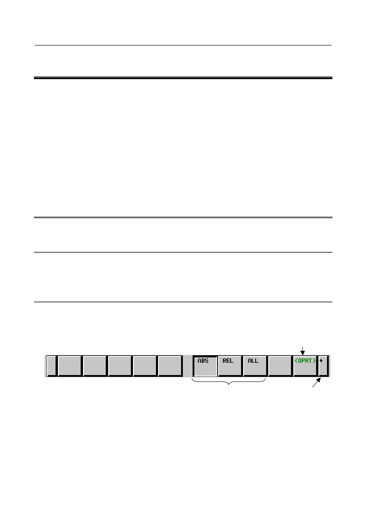
Example 1)
Operation selection key
Chapter selection soft keys
Continuous menu key
2
When one of the chapter selection soft keys is pressed, the screen of the chapter is displayed. If the
soft key of a desired chapter is not displayed, press the continuous menu key.
In a chapter, a further choice may be made from multiple chapters.
3
When the screen of a desired chapter is displayed, press the operation selection key to display
operations to be performed.
4
Select a desired operation with the operation selection soft key.
Depending on the operation to be executed, an auxiliary menu of soft keys is displayed. Perform an
operation according to the indications on the auxiliary menu.
- 1 -
1.DISPLAY AND OPERATION
B-64485EN/01
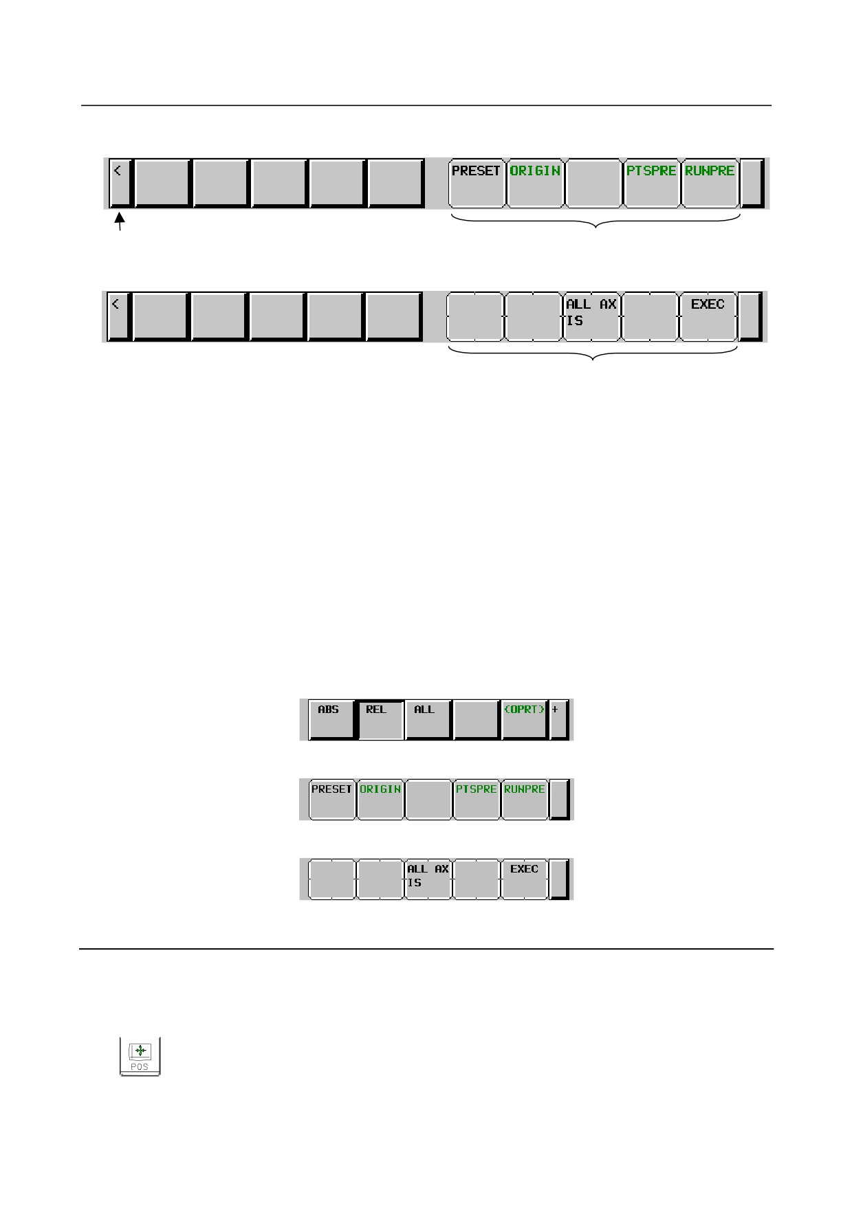
Example 2)
Return menu key
Operation selection soft keys
Example 3)
Auxiliary menu
5
To return to the display of chapter selection soft keys, press the return menu key.
A general screen display procedure is provided above. The actual display procedure varies from one
screen to another.
For details, see each description of operation.
-
Button design change depending on soft key state
The soft keys assume one of the following states, depending on the selection target:
• Chapter selection soft keys
• Operation selection soft keys
• Auxiliary menu of operation selection soft keys
Depending on the state, the button images of the soft keys change.
From the button images, which state the soft keys are assuming can be known.
Example)
•
Chapter selection soft keys
•
Operation selection soft keys
•
Auxiliary menu of operation selection soft keys
1.1.3
Function Keys
Function keys are provided to select the type of screen to be displayed. The following function keys are
provided on the MDI panel:
Press this key to display the position screen.
- 2 -
B-64485EN/01
1.DISPLAY AND OPERATION
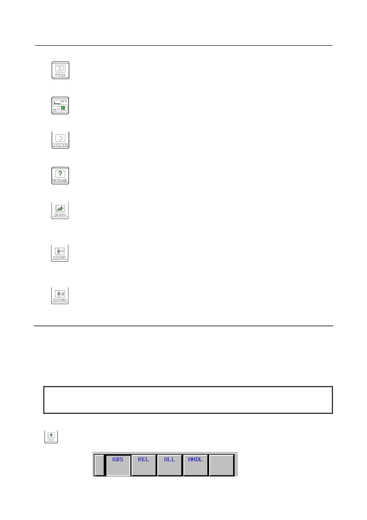
Press this key to display the program screen.
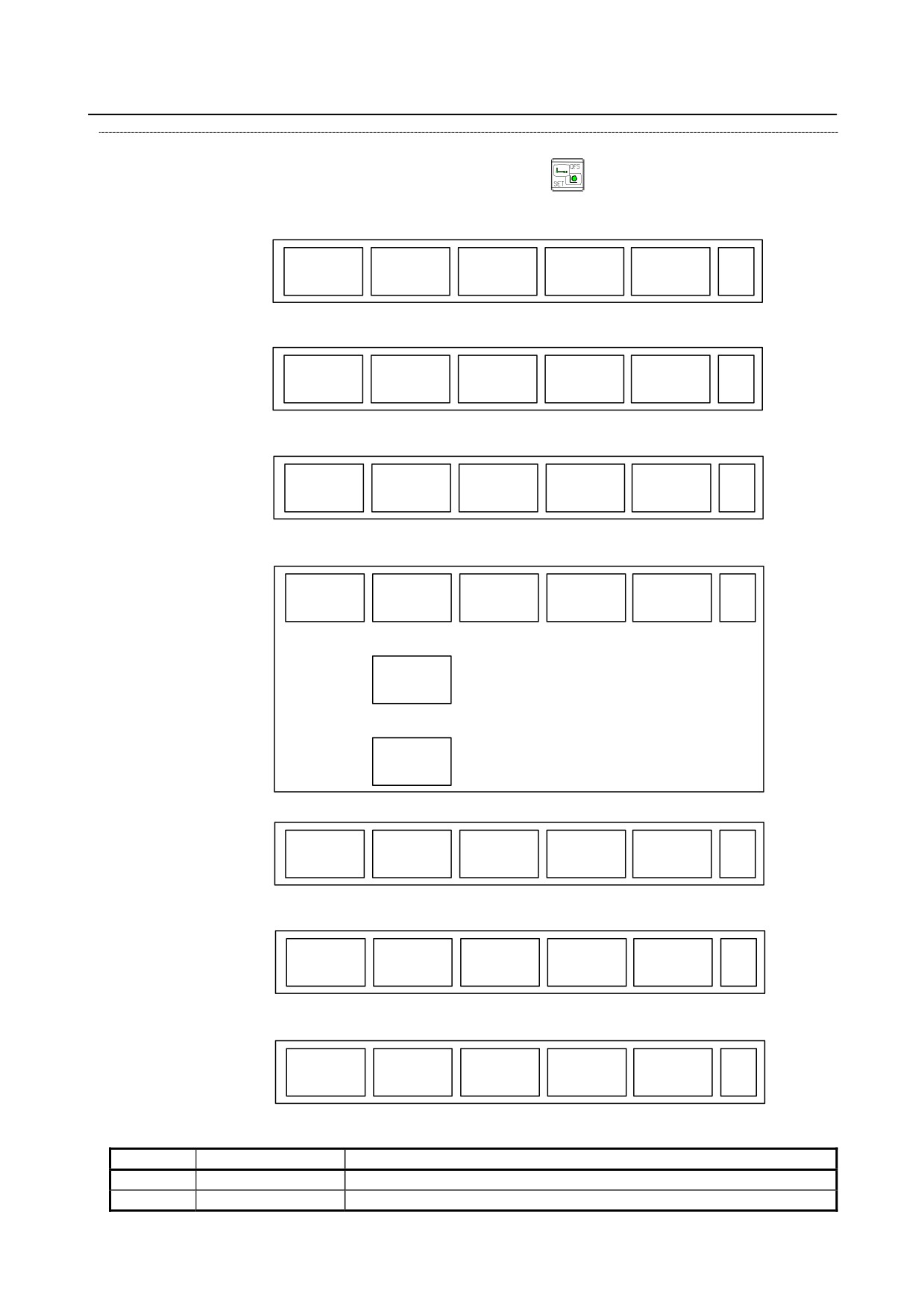
Press this key to display the offset/setting screen.
Press this key to display the system screen.
Press this key to display the message screen.
Press this key to display the graphics screen.
Press this key to display the custom screen 1 (conversational macro screen or C Language Executor
screen).
Press this key to display the custom screen 2 (conversational macro screen or C Language Executor
screen).
1.1.4
Soft Keys
By pressing a soft key after a function key, the corresponding screen of the function can be displayed.
The chapter selection soft keys of each function are described below.
The horizontal four keys on the right-hand side are assigned to chapter selection soft keys. When multiple
pages are used for chapter selection soft keys, [+] is displayed on the continuous menu key (rightmost soft
key). Press the continuous menu key to switch between chapter selection soft keys.
NOTE
1 Press function keys to switch between screens that are used frequently.
2 Some soft keys are not displayed depending on the option configuration.
If position indications are provided on the left half of the screen when a key other than the function key
is pressed, the left half of the soft keys is displayed as follows at all times:
- 3 -
1.DISPLAY AND OPERATION
B-64485EN/01
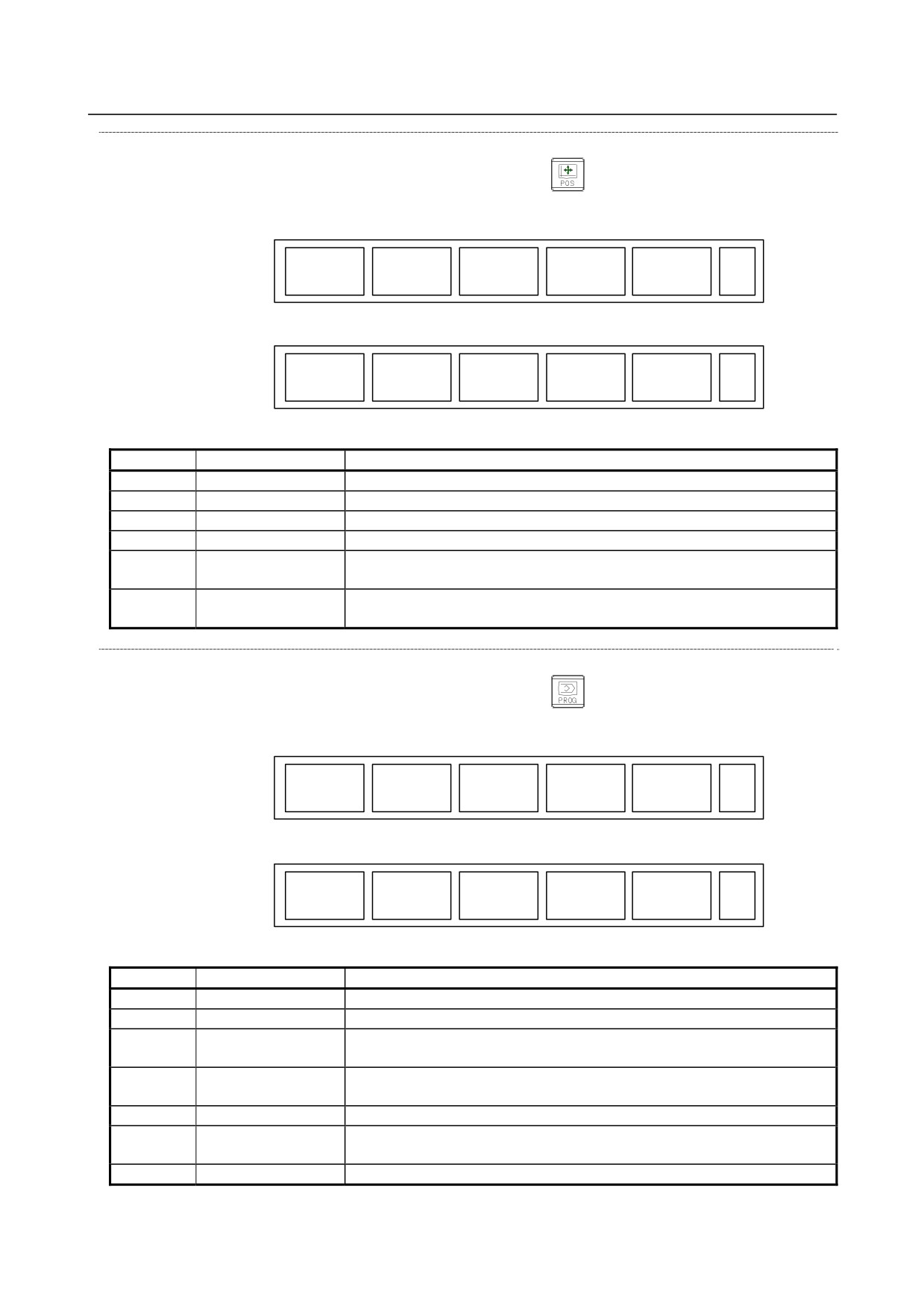
Position display screen
The chapter selection soft keys that belong to the function key
and the function of each screen are
described below.
(1)
(2)
(3)
(4)
(5)
ABS
REL
ALL
HNDL
(OPRT)
+
Page 1
(6)
(7)
(8)
(9)
(10)
MONI
3-D
(OPRT)
+
Page 2
MANUAL
Table 1.1.4 (a) Position display screen
No.
Chapter menu
Description
(1)
ABS
Selects the absolute coordinate display screen.
(2)
REL
Selects the relative coordinate display screen.
(3)
ALL
Selects the overall coordinate display screen.
(4)
HNDL
Selects the operation screen for manual handle operation.
(6)
MONI
Selects the screen for displaying the servo axis load meter, serial spindle load
meter, and speedometer.
(7)
3-D
Displays a handle pulse interrupt amount in three-dimensional manual feed.
MANUAL
Program screen
The chapter selection soft keys that belong to the function key
and the function of each screen are
described below.
(1)
(2)
(3)
(4)
(5)
PROGRA
FOLDER
NEXT
CHECK
(OPRT)
+
Page 1
M
(6)
(7)
(8)
(9)
(10)
TIME
JOG
RSTR
(OPRT)
+
Page 2
Table 1.1.4 (b) Program
No.
Chapter menu
Description
(1)
PROGRAM
Selects the screen for displaying a list of part programs currently registered.
(2)
FOLDER
Selects the screen for displaying a list of part programs currently registered.
(3)
NEXT
Selects the screen for displaying the command values of the block currently
executed and the next block to be executed among the command values.
(4)
CHECK
Selects the screen for displaying programs, position data, modal information,
and so forth simultaneously.
(6)
TIME
Selects the screen for displaying executed program operation time.
(7)
JOG
Selects the screen for executing, in the JOG mode, data specified in the
program format from the MDI.
(8)
RSTR
Selects the operation screen for restarting an interrupted program operation.
- 4 -
B-64485EN/01
1.DISPLAY AND OPERATION
Offset/setting screen
The chapter selection soft keys that belong to the function key
and the function of each screen are
described below.
(1)
(2)
(3)
(4)
(5)
OFFSET
SETTING
WORK
(OPRT)
+
Page 1
(6)
(7)
(8)
(9)
(10)
TOOL
MACRO
OPR
(OPRT)
+
Page 2
MANAGER
(11)
(12)
(13)
(14)
(15)
OFST.2
W.SHFT
GEOM.2
(OPRT)
+
Page 3
(16)
(17)
(18)
(19)
(20)
EXTEND
CHOPP
PR-LV
(OPRT)
+
Page 4
OFFSET
ING
or
MACHIN
LEVEL
or
QUALTY
SELECT
(21)
(22)
(23)
(24)
(25)
CHUCK
LANG.
PROTECT
GUARD
(OPRT)
+
Page 5
TAIL
(26)
(27)
(28)
(29)
(30)
TOOL
(OPRT)
+
Page 6
LIFE
(31)
(32)
(33)
(34)
(35)
WORK
(OPRT)
+
Page 7
SET ER
Table 1.1.4 (c) Offset
No.
Chapter menu
Description
(1)
OFFSET
Selects the screen for setting tool offset values.
(2)
SETTING
Selects the screen for setting the setting parameters.
- 5 -
1.DISPLAY AND OPERATION
B-64485EN/01
No.
Chapter menu
Description
(3)
WORK
Selects the screen for setting a workpiece coordinate system offset.
(6)
MACRO
Selects the screen for setting macro variables.
(8)
OPR
Selects the screen for operating some operation switches on the machine
operator's panel as soft switches.
(9)
TOOL MANAGER
Selects the screen for setting data related to tool management.
(11)
OFST.2
Selects the screen for setting a Y-axis offset.
(12)
W.SHFT
Selects the screen for setting a workpiece coordinate system shift value.
(13)
GEOM.2
Selects the screen for setting a second geometry offset.
(17)
PR-LV
Selects the screen for setting a precision level.
MACHIN LEVEL
Selects the screen for setting a precision level or smoothing level.
QUALTY SELECT
(18)
EXTEND OFFSET
Selects the screen for setting the offsets of the fourth and fifth axes.
(21)
CHUCK TAIL
Selects the chuck tail stock barrier screen.
(22)
LANG.
Selects the screen for setting a display language.
(23)
PROTECT
Selects the screen for setting data protection.
(24)
GUARD
Selects the screen for setting wrong operation prevention.
(29)
TOOL LIFE
Selects the screen for operations and setting related to tool life management.
(31)
WRK ERR COMP
Selects the screen for setting errors related to workpiece mounting position.
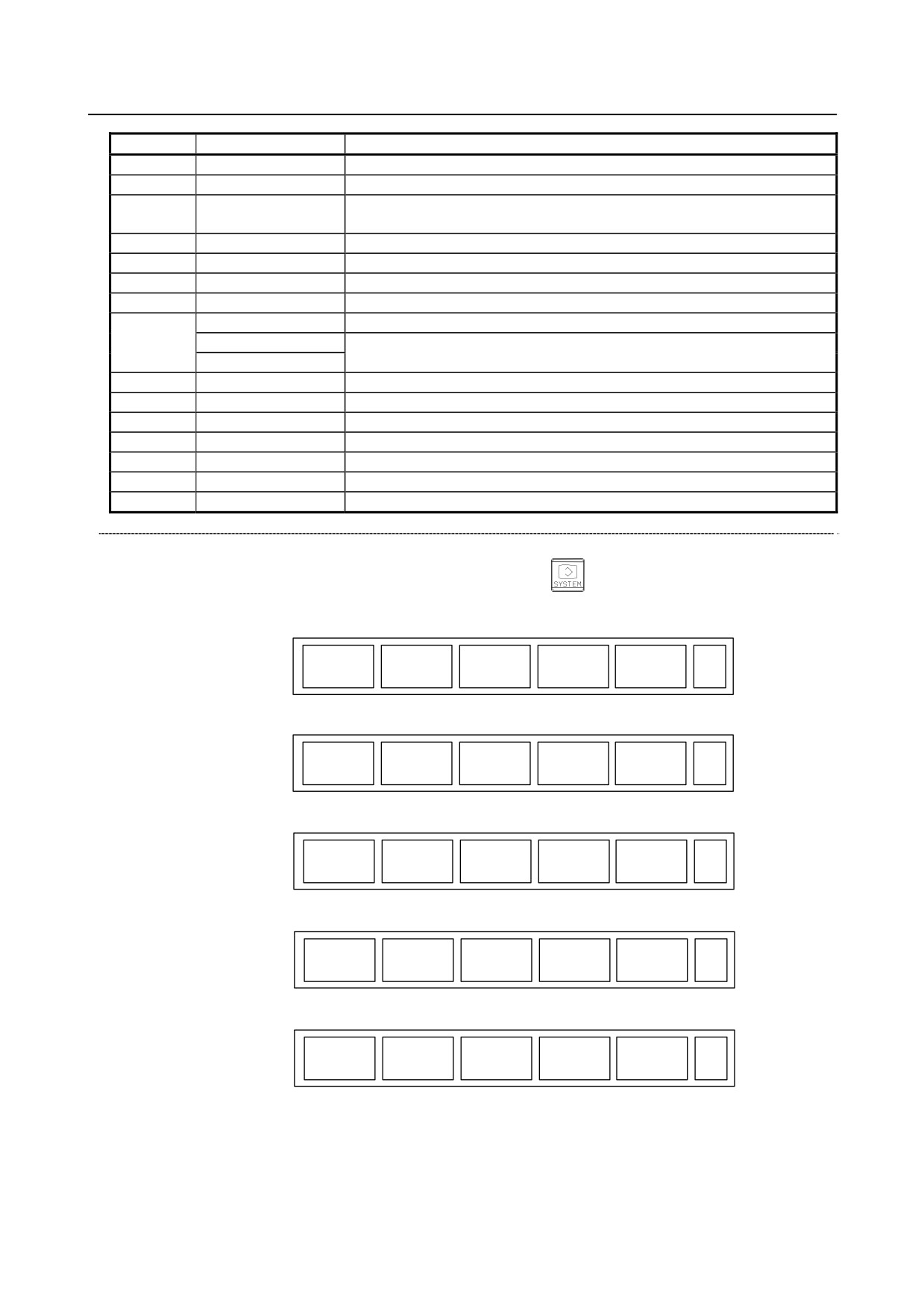
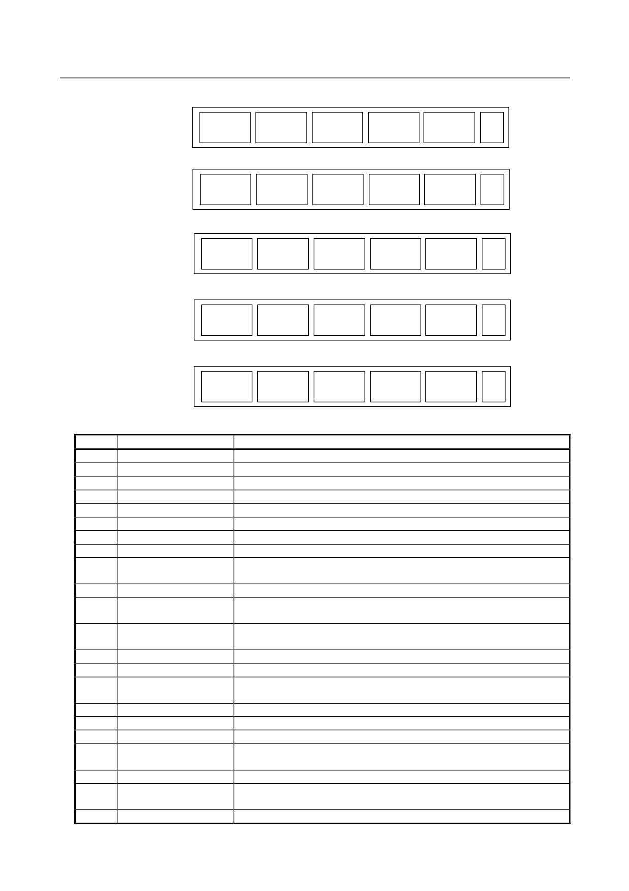
System screen
The chapter selection soft keys that belong to the function key
and the function of each screen are
described below.
(1)
(2)
(3)
(4)
(5)
SERVO
PARAM
DGNOS
SYSTEM
(OPRT)
+
Page 1
GUIDEM
(6)
(7)
(8)
(9)
(10)
MEMORY
PITCH
SERVO
SP.SET
(OPRT)
+
Page 2
PARAM
(11)
(12)
(13)
(14)
(15)
PMC
PMC
PMC
(OPRT)
+
Page 3
MAINTE
LADDER
CONFIG
(16)
(17)
(18)
(19)
(20)
MCNG
ALL IO
ALL IO
OPEHIS
(OPRT)
+
Page 4
TUNING
(21)
(22)
(23)
(24)
(25)
MAINTE
M-INFO
COLOR
W. DGNS
(OPRT)
+
Page 5
- 6 -
B-64485EN/01
1.DISPLAY AND OPERATION
(26)
(27)
(28)
(29)
(30)
TOUCH
P.MATE
FSSB
PRMTUN
(OPRT)
+
Page 6
PANEL
MGR.
(31)
(32)
(33)
(34)
(35)
EMBED
PCMCIA
ETHNET
PROFI
(OPRT)
+
Page 7
PORT
LAN
BOARD
MASTER
(36)
(37)
(38)
(39)
(40)
REMOTE
M CODE
(OPRT)
+
Page 8
DIAG
(41)
(42)
(43)
(44)
(45)
PROFI
DEVNET
(OPRT)
+
Page 9
SLAVE
MASTER
(46)
(47)
(48)
(49)
(50)
DUAL
R.TIME
(OPRT)
+
Page 10
CHECK
MACRO
Table 1.1.4 (d) System
No.
Chapter menu
Description
(1)
PARAM
Selects the screen for setting parameters.
(2)
DGNOS
Selects the screen for displaying CNC state.
(3)
SERVO GUIDEM
Selects the screen for displaying the servo guide mate.
(4)
SYSTEM
Selects the screen for displaying the current system status.
(6)
MEMORY
Selects the screen for displaying the contents of memory.
(7)
PITCH
Selects the screen for setting pith error compensation.
(8)
SERVO PARAM
Selects the screen for setting the servo-related parameters.
(9)
SP.SET
Selects the screen for spindle-related setting.
(11)
PMC MAINTE
Selects the screen related to PMC maintenance such as PMC signal state
monitoring and tracing, and PMC parameter display/editing.
(12)
PMC LADDER
Selects the screen related to ladder display/editing.
(13)
PMC CONFIG
Displays the screen for displaying/editing data other than ladders that makes
up a sequence program and for setting the PMC function.
(16)
MCNG TUNING
Displays the screen for setting the parameter set for emphasis on speed (LV1),
emphasis on precision (LV10), or smoothing level (LV1 or LV10).
(17)
ALL IO
Selects the screen for data input and output.
(18)
ALL IO
Selects the screen for data input to and output from the memory card.
(19)
OPEHIS
Selects the screen for displaying the history of operations performed by the
operator and issued alarms.
(21)
COLOR
Selects the screen for setting colors to be used on the screen.
(22)
MAINTE
Selects the screen for setting maintenance items to be managed periodically.
(23)
M-INFO
Selects the screen for displaying information about maintenance performed.
(24)
W.DGNS
Selects the screen for displaying data such as servo positional deviation
values, torque values, machine signals, and so forth as graphs.
(26)
TOUCH PANEL
Selects the screen for setting a touch panel.
(27)
FSSB
Selects the screen for making settings related to the high-speed serial servo
bus (FSSB: Fanuc Serial Servo Bus).
(28)
PRMTUN
Selects the screen for setting parameters necessary for start-up and tuning.
- 7 -
1.DISPLAY AND OPERATION
B-64485EN/01
No.
Chapter menu
Description
(31)
EMBED PORT
Selects the screen for making settings related to the embedded Ethernet
(embedded port).
(32)
PCMCIA LAN
Selects the screen for making settings related to the embedded Ethernet
(PCMCIA Ethernet card).
(33)
ETHNET BOARD
Selects the screen for making settings related to the fast Ethernet/fast data
server.
(34)
PROFI MASTER
Selects the screen for making settings related to the profibus master function.
(37)
M CODE
Selects the screen for setting an M code group.
(41)
PROFI SLAVE
Selects the screen for making settings related to the profi-bus slave function.
(42)
DEVNETMASTER
Selects the screen for making settings related to the DeviceNet master
function.
(46)
DUAL CHECK
Selects the screen for making settings related to the dual check safety
function.
(47)
R.TIME MACRO
Selects the screen for making settings related to the real-time custom macro
function.
Message screen
The chapter selection soft keys that belong to the function key
and the function of each screen are
described below.
(1)
(2)
(3)
(4)
(5)
ALARM
MSG
HISTRY
MSGHIS
(OPRT)
+
Page 1
(6)
(7)
(8)
(9)
(10)
EMBED
PCMCIA
BOARD
(OPRT)
+
Page 2
LOG
LOG
LOG
Table 1.1.4 (e) Message
No.
Chapter menu
Description
(1)
ALARM
Selects the alarm message screen.
(2)
MSG
Selects the operator message screen.
(3)
HISTRY
Selects the screen for displaying the details of alarms issued so far.
(4)
MSGHIS
Selects the external operator message screen.
(6)
EMBED LOG
Selects the screen for displaying error messages related to the embedded
Ethernet (embedded port).
(7)
PCMCIA LOG
Selects the screen for displaying error messages related to the embedded
Ethernet (PCMCIA Ethernet card).
(8)
BOARD LOG
Selects the screen for displaying error messages related to the fast
Ethernet/fast data server.
Graphic screen
The chapter selection soft keys that belong to the function key
and the function of each screen are
described below.
When the graphic display function is enabled:
- 8 -
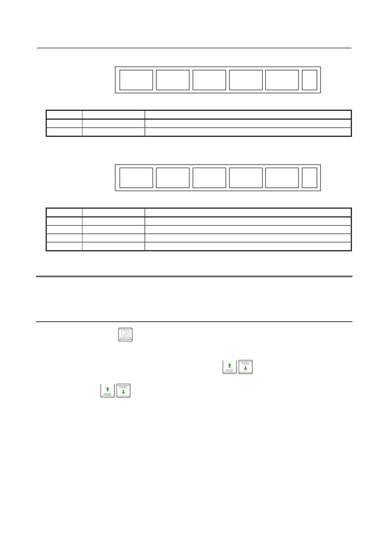
B-64485EN/01
1.DISPLAY AND OPERATION
(1)
(2)
(3)
(4)
(5)
PARAM
GRAPH
(OPRT)
+
Page 1
Table 1.1.4 (f) Graphic
No.
Chapter menu
Description
(1)
PARAM
Selects the screen for setting graphic parameters.
(2)
GRAPH
Selects the screen for graphically displaying the tool path.
When the dynamic graphic display function is enabled:
(1)
(2)
(3)
(4)
(5)
DRAW
PATH
ANIME
TOOL
(OPRT)
Page 1
PARAM
EXEC
EXEC
POS
Table 1.1.4 (g) Graphic
No.
Chapter menu
Description
(1)
DRAW PARAM
Selects the screen for setting drawing parameters.
(2)
PATH EXEC
Selects the screen for drawing tool paths.
(3)
ANIME EXEC
Selects the screen for drawing animation.
(4)
TOOL POS
Selects the screen for displaying tool positions.
1.2
SYSTEM CONFIGURATION SCREEN
After the system has started normally, you can find the types of installed printed circuit boards and
software types by displaying a system configuration screen.
1.2.1
Display Method
1
Press function key
2
Press soft key [SYSTEM].
3
Two types of system configuration screen, the hardware screen and software screen, are provided,
and you can switch between these screens by using the
page keys.
When all information cannot be displayed on one page of the screen, you can switch to the next page
by using the
keys.
- 9 -
1.DISPLAY AND OPERATION
B-64485EN/01
1.2.2
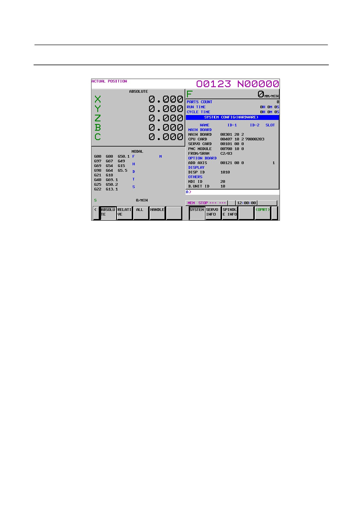
Hardware Configuration Screen
-
Screen display
-
Displayed information
The following explains the displayed information:
1.
NAME
MAIN BOARD
•
Displays information on the main board, and cards and modules on the main board.
OPTION BOARD
•
Displays information on the board installed in the option slot.
DISPLAY
•
Displays information on the display unit.
OTHERS
•
Displays information on other components (such as an MDI and a basic unit).
2.
SLOT
•
Displays the number of the slot in which the option board is inserted.
- 10 -
B-64485EN/01
1.DISPLAY AND OPERATION
1.2.3
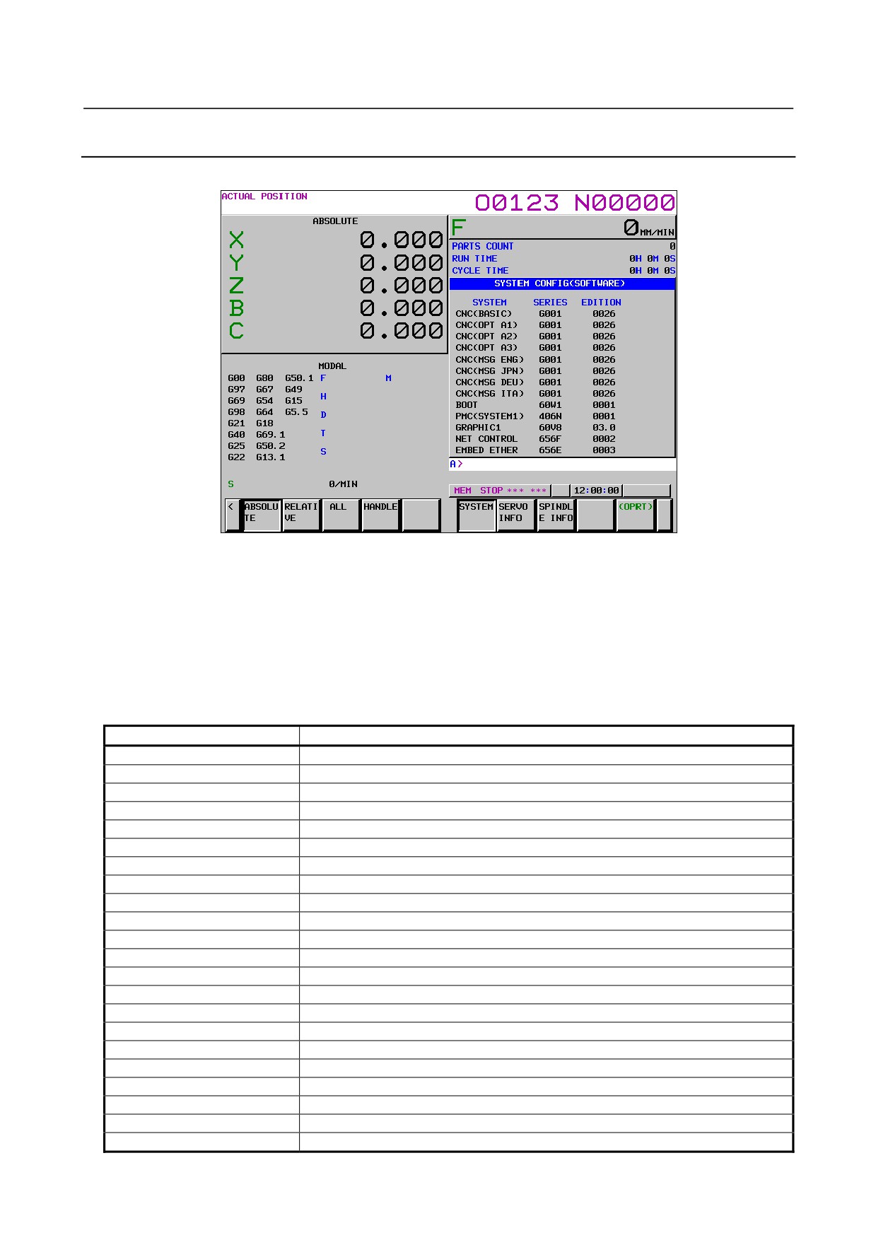
Software Configuration Screen
-
Screen display
-
Displayed information
The following explains the displayed information:
SYSTEM : Software type
SERIES
: Software series
EDITION : Software edition
-
Displayed systems and corresponding software types
The following lists the correspondence between displayed systems and software:
System
Software type
CNC(BASIC)
CNC basic software
CNC(OPT A1)
Option assembly A1
CNC(OPT A2)
Option assembly A2
CNC(OPT A3)
Option assembly A3
CNC(MSG ENG)
Language indication (English)
CNC(MSG JPN)
Language indication (Japanese)
CNC(MSG DEU)
Language indication (German)
CNC(MSG FRA)
Language indication (French)
CNC(MSG CHT)
Language indication (Chinese (traditional characters))
CNC(MSG ITA)
Language indication (Italian)
CNC(MSG KOR)
Language indication (Korean)
CNC(MSG ESP)
Language indication (Spanish)
CNC(MSG NLD)
Language indication (Dutch)
CNC(MSG DAN)
Language indication (Danish)
CNC(MSG PTG)
Language indication (Portuguese)
CNC(MSG PLK)
Language indication (Polish)
CNC(MSG HUN)
Language indication (Hungarian)
CNC(MSG SVE)
Language indication (Swedish)
CNC(MSG CSY)
Language indication (Czech)
CNC(MSG CHS)
Language indication (Chinese (simplified characters))
CNC(MSG RUS)
Language indication (Russian)
CNC(MSG TRK)
Language indication (Turkish)
- 11 -