FANUC Series Series 16i-TB, Series 18i-TB, Series 160i-TB, Series 180i-TB. OPERATOR’S MANUAL - page 27
B-63524EN/01
OPERATION
11. SETTING AND DISPLAYING DATA
11.4.7
Data such as the TV check flag and punch code is set on the setting data
screen. On this screen, the operator can also enable/disable parameter
Displaying and
writing, enable/disable the automatic insertion of sequence numbers in
Entering Setting Data
program editing, and perform settings for the sequence number
comparison and stop function.
See Chapter III-10 for automatic insertion of sequence numbers.
See subsection III-11.4.8 for the sequence number comparison and stop
function. This subsection describes how to set data.
Procedure for setting the setting data
1
Select the MDI mode.
OFFSET
2
Press function key
SETTING
3
Press soft key [SETING] to display the setting data screen.
This screen consists of several pages.
Press page key
or PAGE
until the desired screen is displayed.
PAGE
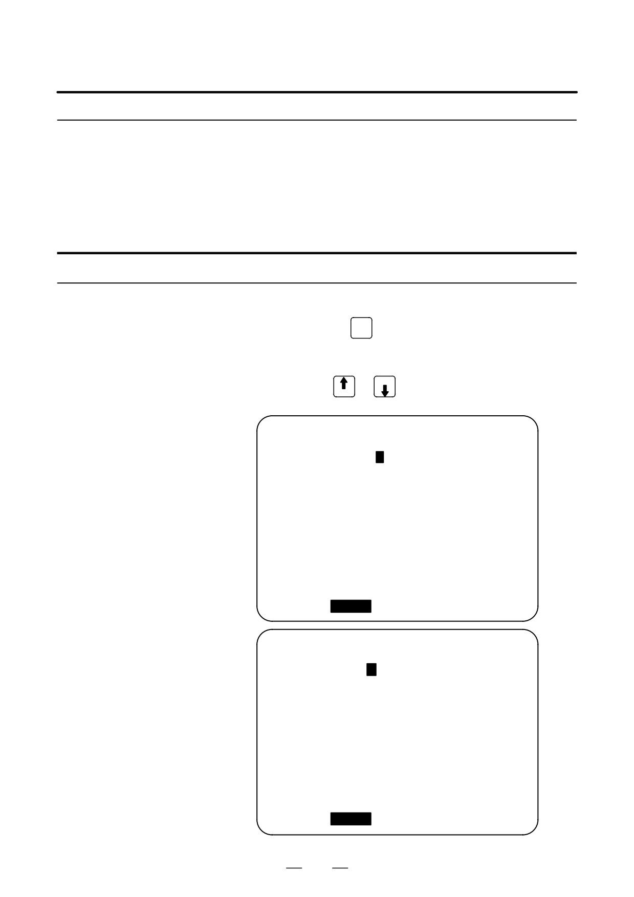
An example of the setting data screen is shown below.
SETTING (HANDY)
O0001 N00000
PARAMETER WRITE = 1
(0:DISABLE 1:ENABLE)
TV CHECK =
0 (0:OFF
1:ON)
PUNCH CODE =
1 (0:EIA
1:ISO)
INPUT UNIT =
0 (0:MM
1:INCH)
I/O CHANNEL
=
0 (0-3:CHANNEL NO.)
SEQUENCE NO. =
0 (0:OFF
1:ON)
TAPE FORMAT
=
0 (0:NO CNV
1:F15)
SEQUENCE STOP =
0 (PROGRAM NO.)
SEQUENCE STOP =
0 (SEQUENCE NO.)
> _
MDI **** *** ***
16:05:59
[ OFFSET ][
SETING
][ WORK ][
][ (OPRT) ]
SETTING (HANDY)
O0001 N00000
MIRROR IMAGE X =
0
(0:OFF
1:ON)
MIRROR IMAGE Z = 0 (0:OFF
1:ON)
> _
MDI **** *** ***
16:05:59
[ OFFSET ][
SETING
][ WORK ][
][ (OPRT) ]
759

11. SETTING AND DISPLAYING DATA
OPERATION
B-63524EN/01
4
Move the cursor to the item to be changed by pressing cursor keys
,
,
, or
5
Enter a new value and press soft key [INPUT].
Contents of settings
D PARAMETER WRITE
Setting whether parameter writing is enabled or disabled.
0 : Disabled
1 : Enabled
D TV CHECK
Setting to perform TV check.
0 : No TV check
1 : Perform TV check
D PUNCH CODE
Setting code when data is output through reader puncher interface.
0 : EIA code output
1 : ISO code output
D INPUT UNIT
Setting a program input unit, inch or metric system
0 : Metric
1 : Inch
D I/O CHANNEL
Using channel of reader/puncher interface.
0 : Channel 0
1 : Channel 1
2 : Channel 2
3 : Channel 3
D SEQUENCE STOP
Setting of whether to perform automatic insertion of the sequence number
or not at program edit in the EDIT mode.
0 : Does not perform automatic sequence number insertion.
1 : Perform automatic sequence number insertion.
D TAPE FORMAT
Setting the F15 tape format conversion.
0 : Tape format is not converted.
1 : Tape format is converted.
See PROGRAMMING for the F15 tape format.
D SEQUENCE STOP
Setting the sequence number with which the operation stops for the
sequence number comparison and stop function and the number of the
program to which the sequence number belongs
D MIRROR IMAGE
Setting of mirror image ON/OFF for each axes.
0 : Mirror image off
1 : Mirror image on
D Others
Page key
or PAGE
can also be pressed to display the SETTING
PAGE
(TIMER) screen. See subsection III-11.4.9 for this screen.
760
B-63524EN/01
OPERATION
11. SETTING AND DISPLAYING DATA
11.4.8
If a block containing a specified sequence number appears in the program
being executed, operation enters single block mode after the block is
Sequence Number
executed.
Comparison and Stop
Procedure for sequence number comparison and stop
1
Select the MDI mode.
OFFSET
2
Press function key
SETTING
3
Press chapter selection soft key [SETING].
4
Press page key
or PAGE
several times until the following screen
PAGE
is displayed.
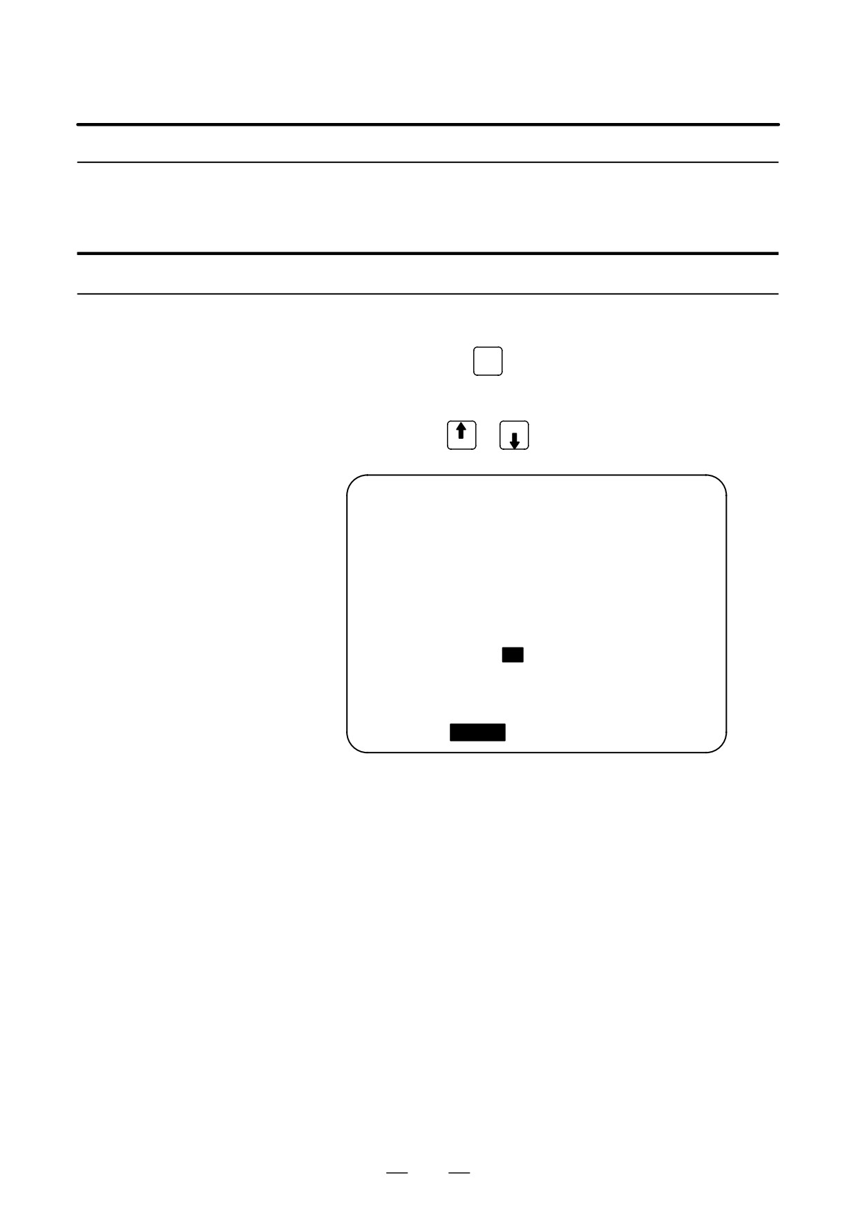
SETTING (HANDY)
O0001 N00000
PARAMETER WRITE = 1 (0:DISABLE 1:ENABLE)
TV CHECK
= 0 (0:OFF
1:ON)
PUNCH CODE
= 1 (0:EIA
1:ISO)
INPUT UNIT
= 0 (0:MM
1:INCH)
I/O CHANNEL
= 0 (0-3:CHANNEL NO.)
SEQUENCE NO.
= 0 (0:OFF
1:ON)
TAPE FORMAT
= 0 (0:NO CNV
1:F10/11)
SEQUENCE STOP
= 0 (PROGRAM NO.)
SEQUENCE STOP
=
11(SEQUENCE NO.)
> _
MDI **** *** ***
16:05:59
[ OFFSET ][
SETING
][ WORK ][
][ (OPRT) ]
5
Enter in (PROGRAM NO.) for SEQUENCE STOP the number (1 to
9999) of the program containing the sequence number with which
operation stops.
6
Enter in (SEQUENCE NO.) for SEQUENCE STOP (with five or less
digits) the sequence number with which operation is stopped.
7
When automatic operation is executed, operation enters single block
mode at the block containing the sequence number which has been
set.
761
11. SETTING AND DISPLAYING DATA
OPERATION
B-63524EN/01
Explanations
D Sequence number after
After the specified sequence number is found during the execution of the
the program is executed
program, the sequence number set for sequence number compensation
and stop is decremented by one. When the power is turned on, the setting
of the sequence number is 0.
D Exceptional blocks
If the predetermined sequence number is found in a block in which all
commands are those to be processed within the CNC control unit, the
execution does not stop at that block.
Example
N1 #1=1 ;
N2 IF [#1 EQ 1] GOTO 08 ;
N3 GOTO 09 ;
N4 M98 P1000 ;
N5 M99 ;
In the example shown above, if the predetermined sequence number is
found, the execution of the program does not stop.
D Stop in the canned cycle
If the predetermined sequence number is found in a block which has a
canned-cycle command, the execution of the program stops after the
return operation is completed.
D When the same
If the predetermined sequence number appears twice or more in a
sequence number is
program, the execution of the program stops after the block in which the
found several times in
predetermined sequence number is found for the first time is executed.
the program
D Block to be repeated a
If the predetermined sequence number is found in a block which is to be
specified number of
executed repeatedly, the execution of the program stops after the block is
times
executed specified times.
762
B-63524EN/01
OPERATION
11. SETTING AND DISPLAYING DATA
11.4.9
Various run times, the total number of machined parts, number of parts
required, and number of machined parts can be displayed. This data can
Displaying and Setting
be set by parameters or on this screen (except for the total number of
Run Time,Parts Count,
machined parts and the time during which the power is on, which can be
and Time
set only by parameters).
This screen can also display the clock time. The time can be set on the
screen.
Procedure for Displaying and Setting Run Time, Parts Count and Time
1
Select the MDI mode.
OFFSET
2
Press function key
SETTING
3
Press chapter selection soft key [SETING].
4
Press page key
or PAGE
several times until the following screen
PAGE
is displayed.
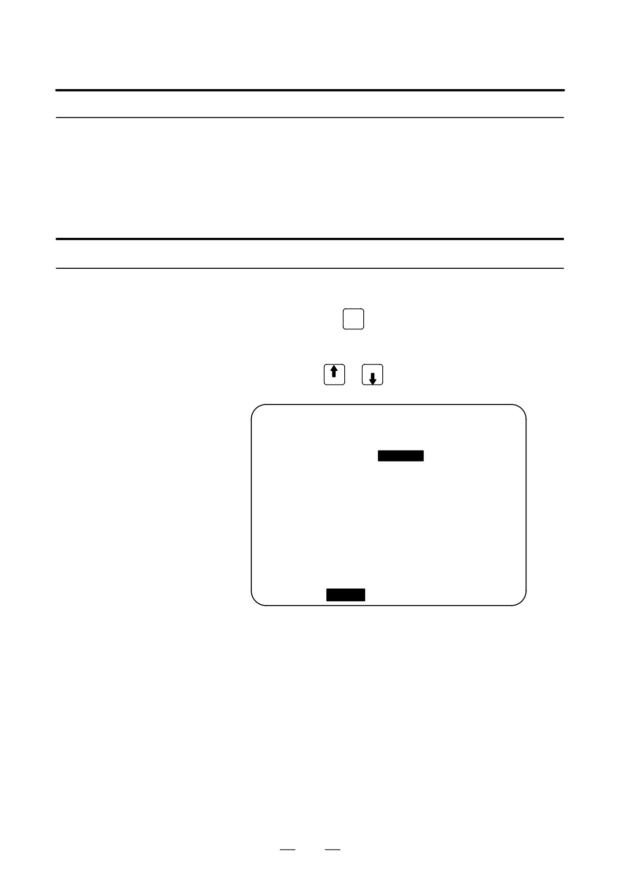
SETTING (TIMER)
O0001 N00000
PARTS TOTAL
=
14
PARTS REQUIRED
=
0
PARTS COUNT
=
23
POWER ON
=
4H 31M
OPERATING TIME
=
0H
0M
0S
CUTTING TIME
=
0H 37M
5S
FREE PURPOSE
=
0H
0M
0S
CYCLE TIME
=
0H
0M
0S
DATE =
2001/06/05
TIME =
11:32:52
> _
S
0 T0000
MDI **** *** ***
16:05:59
[ OFFSET ][
SETING
][ WORK ][
][ (OPRT) ]
5
To set the number of parts required, move the cursor to PARTS
REQUIRED and enter the number of parts to be machined.
6
To set the clock, move the cursor to DATE or TIME, enter a new date
or time, then press soft key [INPUT].
Display items
D PARTS TOTAL
This value is incremented by one when M02, M30, or an M code specified
by parameter 6710 is executed. This value cannot be set on this screen.
Set the value in parameter 6712.
D PARTS REQUIRED
It is used for setting the number of machined parts required.
When the “0” is set to it, there is no limitation to the number of parts.
Also, its setting can be made by the parameter (No. 6713).
763

11. SETTING AND DISPLAYING DATA
OPERATION
B-63524EN/01
D PARTS COUNT
This value is incremented by one when M02, M30, or an M code specified
by parameter 6710 is executed. The value can also be set by parameter
6711. In general, this value is reset when it reaches the number of parts
required. Refer to the manual issued by the machine tool builder for
details.
D POWER ON
Displays the total time which the power is on. This value cannot be set
on this screen but can be preset in parameter 6750.
D OPERATING TIME
Indicates the total run time during automatic operation, excluding the stop
and feed hold time.
This value can be preset in parameter 6751 or 6752.
D CUTTING TIME
Displays the total time taken by cutting that involves cutting feed such as
linear interpolation (G01) and circular interpolation (G02 or G03). This
value can be preset in parameter 6753 or 6754.
D FREE PURPOSE
This value can be used, for example, as the total time during which coolant
flows. Refer to the manual issued by the machine tool builder for details.
D CYCLE TIME
Indicates the run time of one automatic operation, excluding the stop and
feed hold time. This is automatically preset to 0 when a cycle start is
performed at reset state. It is preset to 0 even when power is removed.
D DATA and TIME
Displays the current date and time. The date and time can be set on this
screen.
Explanations
D Usage
When the command of M02 or M30 is executed, the total number of
machined parts and the number of machined parts are incremented by one.
Therefore, create the program so that M02 or M30 is executed every time
the processing of one part is completed. Furthermore, if an M code set
to the parameter (No. 6710) is executed, counting is made in the similar
manner. Also, it is possible to disable counting even if M02 or M30 is
executed (parameter PCM (No. 6700#0) is set to 1). For details, see the
manual issued by machine tool builders.
Restrictions
D Run time and part count
Negative value cannot be set. Also, the setting of “M” and “S” of run time
settings
is valid from 0 to 59.
Negative value may not be set to the total number of machined parts.
D Time settings
Neither negative value nor the value exceeding the value in the following
table can be set.
Item
Maximum value
Item
Maximum value
Year
2085
Hour
23
Month
12
Minute
59
Day
31
Second
59
764
B-63524EN/01
OPERATION
11. SETTING AND DISPLAYING DATA
11.4.10
Displays the workpiece origin offset for each workpiece coordinate
system (G54 to G59) and external workpiece origin offset. The workpiece
Displaying and Setting
origin offset and external workpiece origin offset can be set on this screen.
the Workpiece Origin
Offset Value
Procedure for Displaying and Setting the Workpiece Origin Offset Value
OFFSET
1
Press function key
SETTING
2
Press chapter selection soft key [WORK].
The workpiece coordinate system setting screen is displayed.
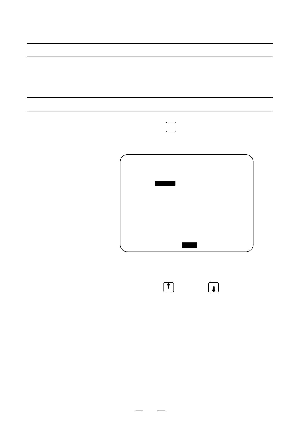
WORK COORDINATES
O0001 N00000
NO.
DATA
NO.
DATA
02
X 152.580
00
X
0.000
(EXT) Z
0.000
(G55) Z 234.000
01
X
20.000
03
X 300.000
(G54) Z
50.000
(G56) Z 200.000
> _
S
0 T0000
MDI **** *** ***
16:05:59
[ OFFSET ][ SETING ][
WORK
][
][ (OPRT) ]
3
The screen for displaying the workpiece origin offset values consists
of two or more pages. Display a desired page in either of the
following two ways:
Press the page up
or page down PAGE
key.
PAGE
Enter the workpiece coordinate system number
(0: external
workpiece origin offset, 1 to 6: workpiece coordinate systems G54 to
G59) and press operation selection soft key [NO.SRH].
4
Turn off the data protection key to enable writing.
5
Move the cursor to the workpiece origin offset to be changed.
6
Enter a desired value by pressing numeric keys, then press soft key
[INPUT]. The entered value is specified in the the workpiece origin
offset value. Or, by entering a desired value with numeric keys and
pressing soft key [+INPUT], the entered value can be added to the
previous offset value.
7
Repeat 5 and 6 to change other offset values.
8
Turn on the data protection key to disable writing.
765
11. SETTING AND DISPLAYING DATA
OPERATION
B-63524EN/01
11.4.11
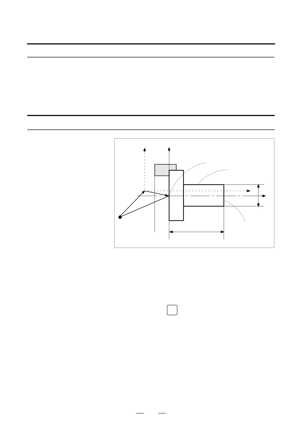
This function is used to compensate for the difference between the
programmed workpiece coordinate system and the actual workpiece
Direct Input of
coordinate system. The measured offset for the origin of the workpiece
Measured Workpiece
coordinate system can be input on the screen such that the command
Origin Offsets
values match the actual dimensions.
Selecting the new coordinate system matches the programmed coordinate
system with the actual coordinate system.
Procedure for Inputting of Measured Workpiece Origin Offsets
x
X
Programmed workpiece origin
Surface B
O
z
α
Z
Previous
O’
offset
New offset
Origin
Surface A
β
1
When the workpiece is shaped as shown above, cut surface A
manually.
2
Move the tool along the X axis without changing the Z coordinate
then stop the spindle.
3
Measure distance β between surface A and the programmed origin of
the workpiece coordinate system as shown above.
OFFSET
4
Press function key
SETTING
766

B-63524EN/01
OPERATION
11. SETTING AND DISPLAYING DATA
5
To display the workpiece origin offset setting screen, press the
chapter selection soft key [WORK].
WORK COORDINATES
O1234 N56789
(G54)
NO.
DATA
NO.
DATA
00
X
0.000
02
X
0.000
(EXT) Z
0.000
(G55)Z
0.000
01
X
0.000
03
X
0.000
(G54) Z
0.000
(G56) Z
0.000
> Z100.
S
0 T0000
MDI **** *** ***
16:05:59
[ NO.SRH ][ MEASUR ][
][ +INPUT ][ INPUT ]
6
Position the cursor to the workpiece origin offset value to be set.
7
Press the address key for the axis along which the offset is to be set
(Z-axis in this example).
8
Enter the measured value (α) then press the [MEASUR] soft key.
9
Cut surface B manually.
10
Move the tool along the Z axis without changing the X coordinate
then stop the spindle.
11
Measure the diameter of surface A (α) then enter the diameter at X.
Restrictions
D Consecutive input
Offsets for two or more axes cannot be input at the same time.
D During program
This function cannot be used while a program is being executed.
execution
D Effect from other shift
Any shift specified for the workpiece coordinate system or external offset
value
remains effective when this function is used.
767
11. SETTING AND DISPLAYING DATA
OPERATION
B-63524EN/01
11.4.12
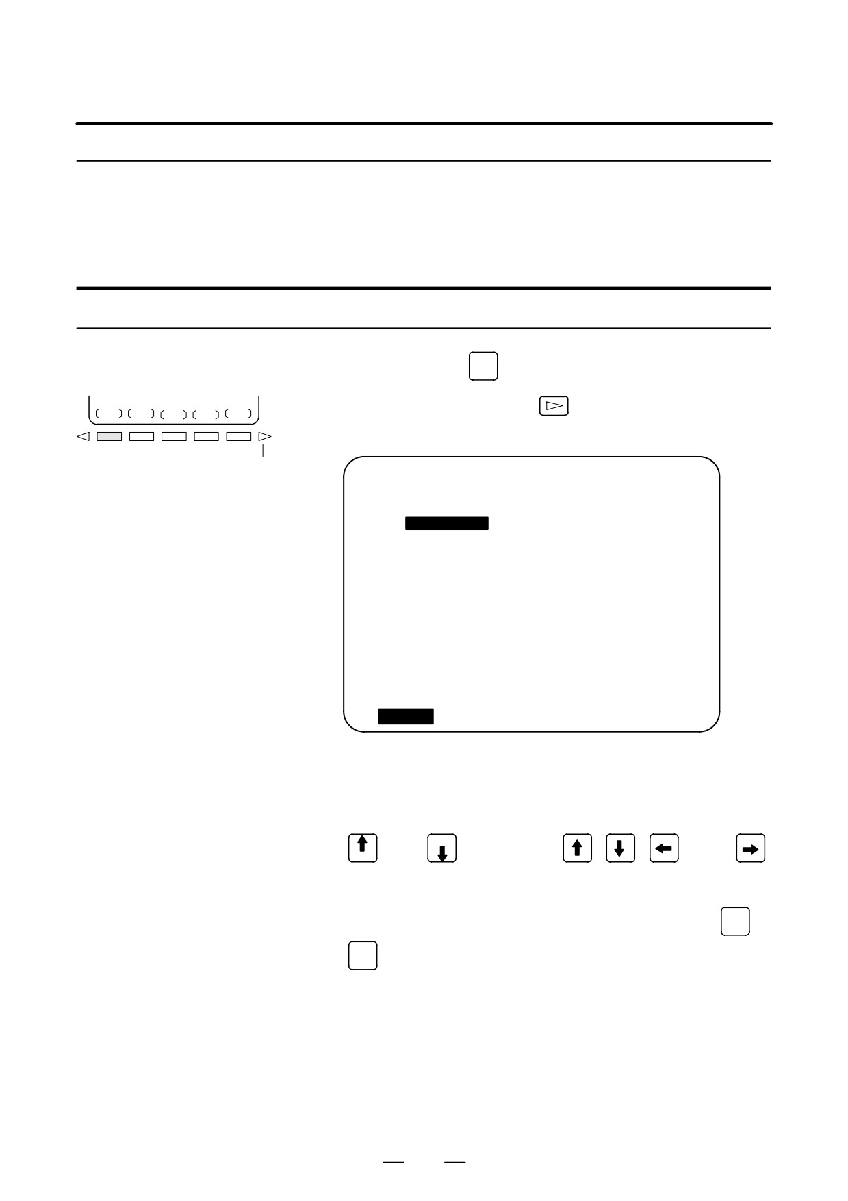
Displays common variables (#100 to #149 or #100 to #199, and #500 to
#531 or #500 to #999) on the CRT. When the absolute value for a common
Displaying and Setting
variable exceeds 99999999, ******** is displayed. The values for
Custom Macro
variables can be set on this screen. Relative coordinates can also be set
Common Variables
to variables.
Procedure for displaying and setting custom macro common variables
OFFSET
1
Press function key
SETTING
2
Press the continuous menu key
, then press chapter selection soft
MACRO
key [MACRO]. The following screen is displayed:
Continuous menu key
VARIABLE
O0001 N00000
NO.
DATA
NO.
DATA
100
1000.000
108
0.000
101
0.000
109
40000.000
102
-50000.000
110
153020.00
103
0.000
111
0001.000
104
1238501.0
112
0.000
105
0.000
113
20000.000
106
0.000
114
0.000
107
0.000
115
0.000
ACTUAL POSITION (RELATIVE)
U0.000
W 0.000
> _
S
0 T0000
MDI **** *** ***
16:05:59
[
NO.SRH
][
][ INP.C. ][
][ INPUT ]
3
Move the cursor to the variable number to set using either of the
following methods:
- Enter the variable number and press soft key [NO.SRH].
- Move the cursor to the variable number to set by pressing page keys
and/or PAGE
and cursor keys
,
,
, and/or
PAGE
4
Enter data with numeric keys and press soft key [INPUT].
5
To set a relative coordinate in a variable, press address key
X
or
Z
, then press soft key [INP.C.].
6
To set a blank in a variable, just press soft key [INPUT]. The value
field for the variable becomes blank.
768
B-63524EN/01
OPERATION
11. SETTING AND DISPLAYING DATA
11.4.13
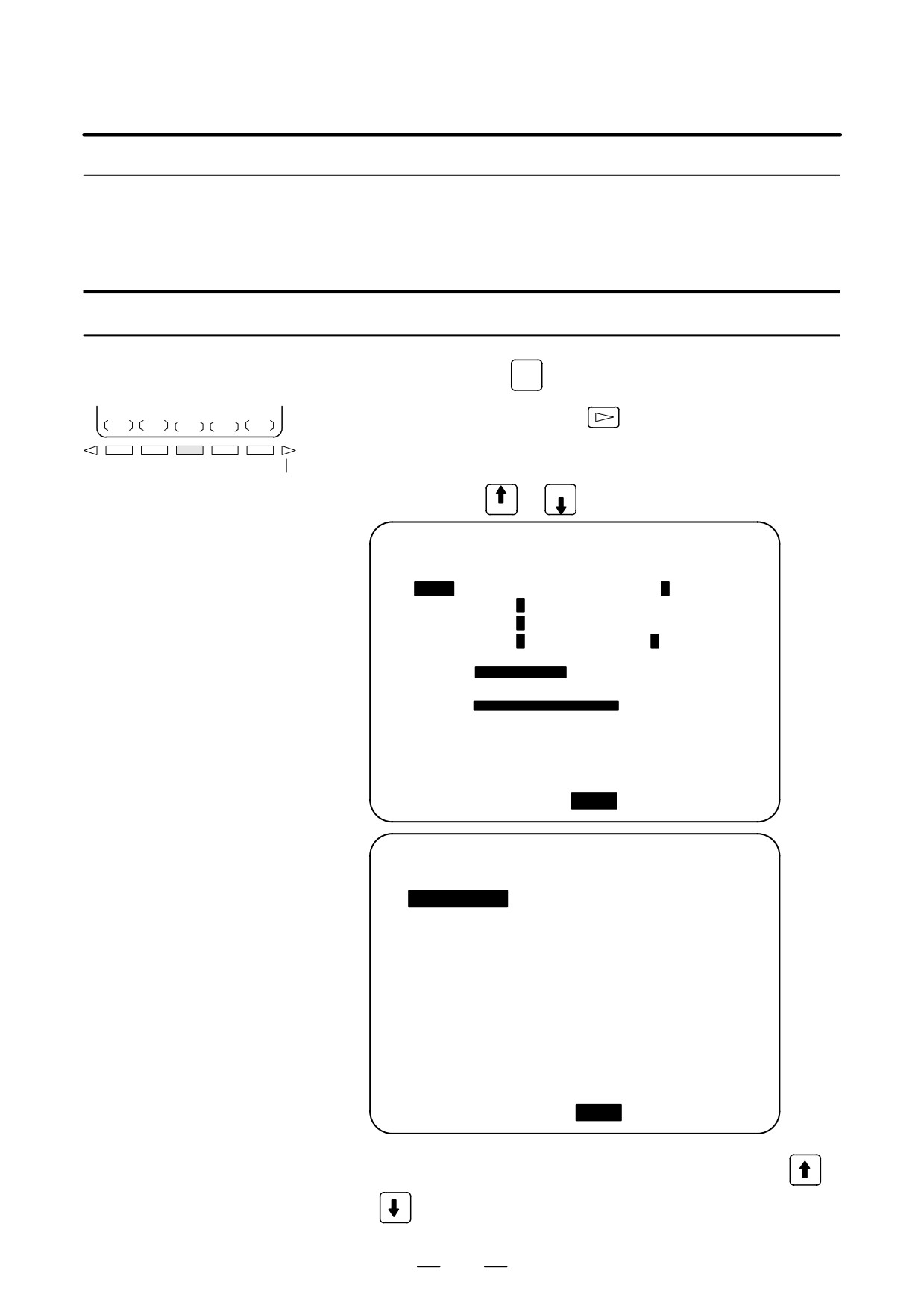
With this function, functions of the switches on the machine operator’s
panel can be controlled from the MDI panel.
Displaying and Setting
Jog feed can be performed using numeric keys.
the Software
Operator’s Panel
Procedure for displaying and setting the software operator’s panel
OFFSET
1
Press function key
SETTING
2
Press the continuous menu key
, then press chapter selection soft
OPR
key [OPR].
3
The screen consists of several pages.
Continuous menu key
Press page key
or PAGE
until the desired screen is displayed.
PAGE
OPERATOR’S PANEL
O0000 N00000
MODE
: MDI MEM EDIT HND JOG
REF
HANDLE AXIS :
HX
HZ
HC
HY
STEP MULTI. :
*1
*10
*100
RAPID OVRD. :
100%
50%
25%
F0
JOG OVRD
:
2.0%
**************
FEED OVRD.
:
100%
***
ACTUAL POSITION (ABSOLUTE)
X
0.000
Z
0.000
>_
REF **** *** ***
16:05:59
[ MACRO
][ MEMu
][
OPR
][
][
]
OPERATOR’S PANEL
O0000 N00000
BLOCK SKIP
:
OFF J ON
SINGLE BLOCK :
J OFF ON
MACHINE LOCK :
OFF J ON
PROTECT KEY
:
J PROTECT
RELEASE
FEED HOLD
:
J OFF
ACTUAL POSITION (ABSOLUTE)
X
0.000
Z
0.000
MDI **** *** ***
16:05:59
[ MACRO
][ MENU
][
OPR
][
][
]
4
Move the cursor to the desired switch by pressing cursor key
or
769
11. SETTING AND DISPLAYING DATA
OPERATION
B-63524EN/01
5
Push the cursor move key
or
to match the mark J to an
arbitrary position and set the desired condition.
6
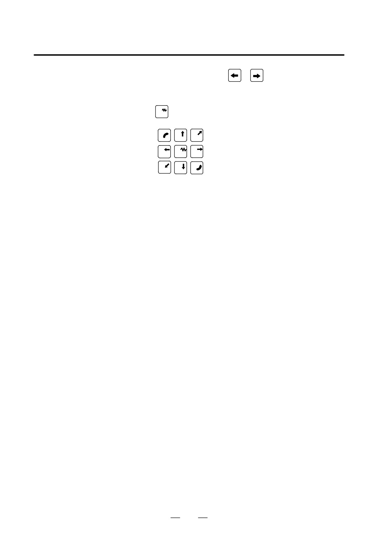
Press one of the following arrow keys to perform jog feed. Press the
5
key together with an arrow key to perform manual continuous
rapid traverse.
7
8
9
4
5
6
1
2
6
Explanations
D Valid operations
The valid operations on the software operator’s panel are shown below.
Whether to use the CRT or machine operator’s panel for each group of
operations can be selected by parameter 7200.
Group1 : Mode selection
Group2 : Selection of jog feed axis, manual continuous rapid traverse
Group3 : Selection of manual pulse generator feed axis, selection of
manual pulse magnification x1, x10, x100
Group4 : Jog federate, federate override, rapid traverse override
Group5 : Optional block skip, single block, machine lock, dry run
Group6 : Protect key
Group7 : Feed hold
D Display
The groups for which the machine operator’s panel is selected by
parameter 7200 are not displayed on the software operator’s panel.
D Screens on which jog
When the CRT indicates other than the software operator’s panel screen
feed is valid
and diagnostic screen, jog feed is not conducted even if the arrow key is
pushed.
D Jog feed and arrow keys
The feed axis and direction corresponding to the arrow keys can be set
with parameters (Nos. 7210 to 7217).
D General purpose
Eight optionally definable switches are added as an extended function of
switches
the software operator’s panel. The name of these switches can be set by
parameters as character strings of max. 8 characters. For the meanings of
these switches, refer to the manual issued by machine tool builder.
770
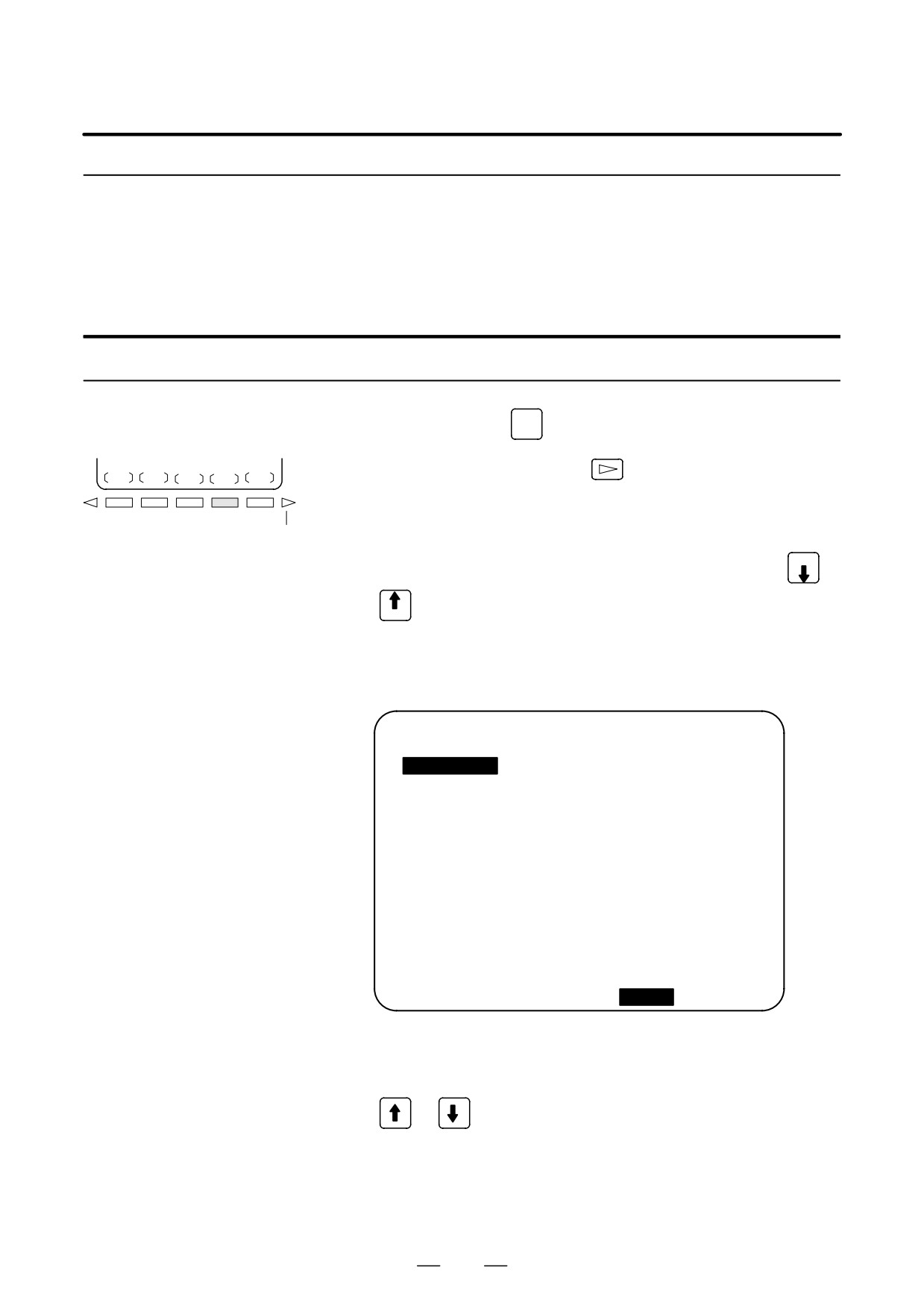
B-63524EN/01
OPERATION
11. SETTING AND DISPLAYING DATA
11.4.14
Tool life data can be displayed to inform the operator of the current state
of tool life management. Groups which require tool changes are also
Displaying and Setting
displayed. The tool life counter for each group can be preset to an
Tool Life Management
arbitrary value. Tool data (execution data) can be reset or cleared. To
Data
register or modify tool life management data, a program must be created
and executed. See Explanations in this section for details.
Procedure for display and setting the tool life management data
OFFSET
1
Press function key
SETTING
2
Press the continuous menu key
to display chapter selection soft
TOOLLF
key [TOOLLF].
3
Press soft key [TOOLLF].
Continuous menu key
4
One page displays data on two groups. Pressing page key PAGE
or
successively displays data on the following groups. Up to four
PAGE
group Nos., for which the Tool Change signal is being issued, are
displayed at the bottom of each page. An arrow shown in the figure is
displayed for five or more groups, if exists.
TOOL LIFE DATA
:
O3000 N00060
SELECTED GROUP 000
GROUP
001
: LIFE
0150
COUNT
0000
0034 0078 0012 0056
0090 0035 0026 0061
0000 0000 0000 0000
0000 0000 0000 0000
GROUP
002 : LIFE
1400
COUNT
0000
0062 0024 0044 0074
0000 0000 0000 0000
0000 0000 0000 0000
0000 0000 0000 0000
TO BE CHANGED
: 003 004 005 006 --->
> _
MEM **** *** ***
16:05:59
[ MACRO ][
][ OPR
][
TOOLLF
][ (OPRT) ]
5
To display the page containing the data for a group, enter the group
number and press soft key [NO.SRH].
The cursor can be moved to an arbitrary group by pressing cursor key
or
6
To change the value in the life counter for a group, move the cursor to
the group, enter a new value (four digits), and press [INPUT]. The life
counter for the group indicated by the cursor is preset to the entered
value. Other data for the group is not changed.
771
11. SETTING AND DISPLAYING DATA
OPERATION
B-63524EN/01
7
To reset the tool data, move the cursor on the group to reset, then press
the [(OPRT)], [CLEAR], and [EXEC] soft keys in this order.
All execution data for the group indicated by the cursor is cleared
together with the marks (@, #, or *).
Explanations
D Registering tool life
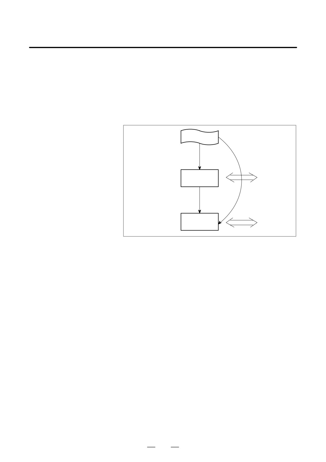
The tool life management data must be executed to register it in the CNC
management data
memory.
(3) TAPE mode
(1) EDIT mode
Editing
Display
Part program
storage &
Memory
editing area
(2) MEM mode
Counter
presenting
Tool life data area
Memory
Display
(1) Load the program for tool life management in the EDIT mode, as with
an ordinary CNC tape.
The program will be registered in the part program memory and will
be made ready for display and editing.
(2) Perform a cycle start operation in the MEM mode to run the program.
The data will be stored in the tool life data area of the memory; at the
same time, the already existing tool life data of all groups will be
cancelled and the life counters will be cleared. Data once stored is not
erased by turning the power off.
(3) Executing a cycle start operation in the TAPE mode instead of the
operation of (1), stores the program contents directly onto the tool life
data area. In this case, however, display and editing cannot be done as
in (1). TAPE mode is not always prepared according to the machine
tool builders.
772
B-63524EN/01
OPERATION
11. SETTING AND DISPLAYING DATA
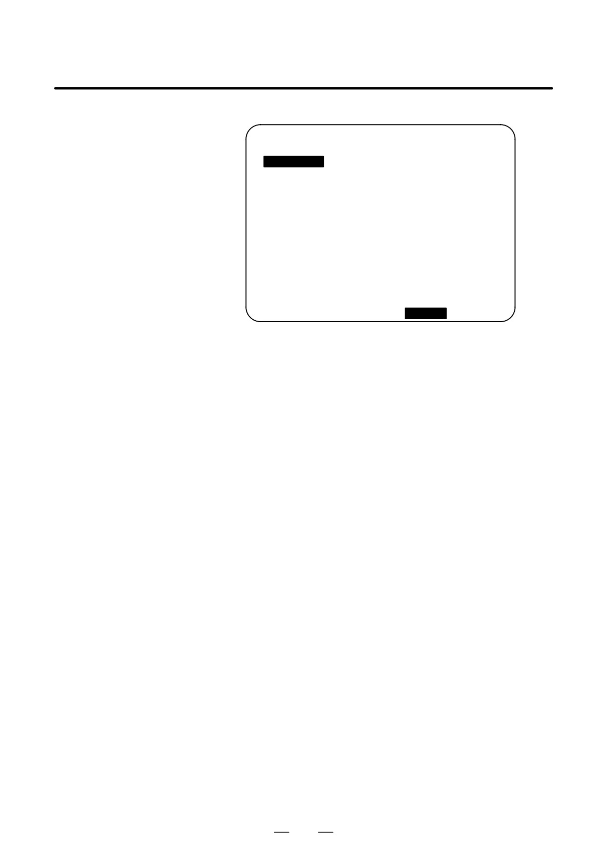
D Display contents
TOOL LIFE DATA
:
O3000 N00060
SELECTED GROUP 000
GROUP
001
: LIFE 0150 COUNT
0007
* 0034
# 0078
@ 0012
0056
0090
0035
0026
0061
0000
0000
0000
0000
0000
0000
0000
0000
GROUP
002
: LIFE 1400 COUNT
0000
0062
0024
0044
0074
0000
0000
0000
0000
0000
0000
0000
0000
0000
0000
0000
0000
TO BE CHANGED
:
003 004 005 006 --->
> _
MEM **** *** ***
16:05:59
[ MACRO ][
][ OPR
][
TOOLLF ][ (OPRT) ]
D
The first line is the title line.
D
In the second line the group number of the current command is
displayed.
When there is no group number of the current command, 0 is
displayed.
D
In lines 3 to 7 the tool life data of the group is displayed.
The third line displays group number, life and the count used.
The life count is chosen by parameter LTM (No. 6800#2) as either
minutes(or hours) or number of times used.
In lines 4 to 7, tool numbers are displayed. In this case, the tool is
selected in the order, 0034 → 0078 → 0012 → 056 → 0090 ...
The meaning of each mark before the tool numbers is:
* : Shows the life has finished.
# : Shows that the skip command has been accepted.
@ : Shows that the tool is currently being used.
The life counter counts for tool with @.
“*” is displayed when the next command is issued by the group to
which it belongs.
D
Lines 8 to 12 are next group life data to the group displayed in lines
3 to 7.
D
In the thirteenth line the group number when the tool change signal is
being emitted is displayed. The group number display appears in
ascending order. When it cannot be completely displayed, “--->” is
displayed.
773
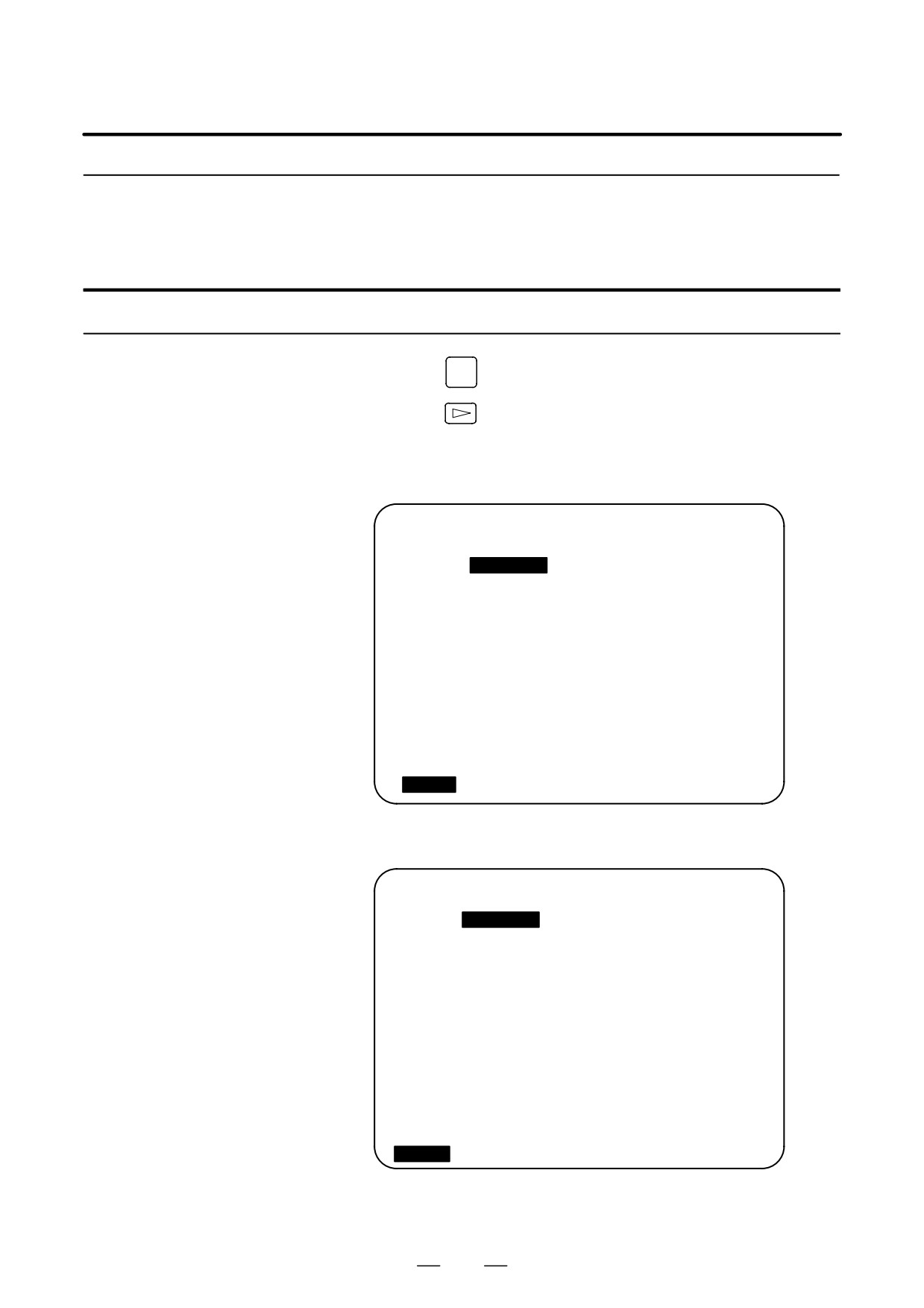
11. SETTING AND DISPLAYING DATA
OPERATION
B-63524EN/01
11.4.15
Setting and Displaying
B-axis Tool
Compensation
Setting and displaying B-axis tool compensation
OFFSET
1
Press the
SETTING
function key.
2
Press the
continuous menu key several times. Then, press the
[OFST.B] chapter selection key.
D When the option for tool geometry and wear compensation is
not provided,
OFFSET (B-AXIS)
O0200 N00000
No.
DATA
51
-999.999
52
-999.999
53
-999.999
54
-999.999
55
-999.999
56
-999.999
57
-999.999
58
-999.999
59
-999.999
>_
S
0 T0000
MDI **** *** ***
15:29:51
[
OFST.B ] [
] [
] [
] [
]
D When the option for tool geometry and wear compensation is
provided,
OFFSET (B-AXIS)
O0200 N00000
NO.
(WEAR)
(GEOMETRY)
51
-999.999
-999.999
52
-999.999
-999.999
53
-999.999
-999.999
54
-999.999
-999.999
55
-999.999
-999.999
56
-999.999
-999.999
57
-999.999
-999.999
58
-999.999
-999.999
59
-999.999
-999.999
>_
S
0 T0000
MDI **** *** ***
15:29:51
[
OFST.B ] [
] [
] [
] [
]
3
Position the cursor to the item to be set or modified, using the cursor
keys.
774

B-63524EN/01
OPERATION
11. SETTING AND DISPLAYING DATA
4
Enter the value, then press the
INPUT
key.
Explanations
The offset can be set to a value in the following valid data ranges.
Offset
Metric input
Inch input
IS-B
-999.999 to 999.999
-99.9999 to 99.9999
IS-C
-999.9999 to 999.9999
-99.99999 to 99.9999
Special B-axis offsets are input or output together with usual offsets.
When the option for tool geometry and wear compensation is provided,
wear offsets and geometry offsets can be specified separately. A tool
offset consists of both the specified wear offset and geometry offset.
In two-path control, tool offsets can be specified for each tool post or both
tool posts, depending on the setting of COF, bit 0 of parameter No. 8242.
775
11. SETTING AND DISPLAYING DATA
OPERATION
B-63524EN/01
When the CNC and machine are connected, parameters must be set to
11.5
determine the specifications and functions of the machine in order to fully
SCREENS DISPLAYED
utilize the characteristics of the servo motor or other parts.
SYSTEM
This chapter describes how to set parameters on the MDI panel.
Parameters can also be set with external input/output devices such as the
Handy File (see Chapter III-9).
In addition, pitch error compensation data used for improving the
precision in positioning with the ball screw on the machine can be set or
SYSTEM
displayed by the operations under function key
See Chapter III-7 for the diagnostic screens displayed by pressing
SYSTEM
function key
776
B-63524EN/01
OPERATION
11. SETTING AND DISPLAYING DATA
11.5.1
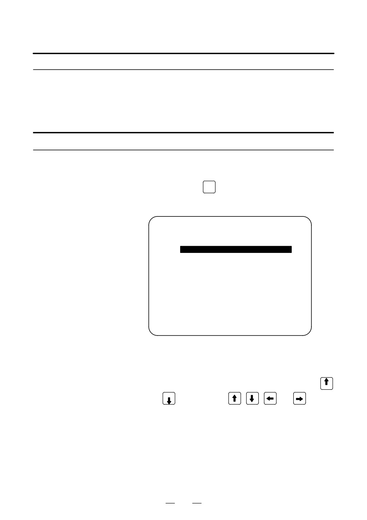
When the CNC and machine are connected, parameters are set to
determine the specifications and functions of the machine in order to fully
Displaying and Setting
utilize the characteristics of the servo motor. The setting of parameters
Parameters
depends on the machine. Refer to the parameter list prepared by the
machine tool builder.
Normally, the user need not change parameter setting.
Procedure for displaying and setting parameters
1
Set 1 for PARAMETER WRITE to enable writing. See the procedure
for enabling/disabling parameter writing described below.
SYSTEM
2
Press function key
3
Press chapter selection soft key [PARAM] to display the parameter
screen.
PARAMETER (SETTING)
O0010 N00002
0000
SEQ
INI ISO
TVC
0
0
0
0
0
0
0
0
0001
FCV
0
0
0
0
0
0
0
0
0012
MIR
X
0
0
0
0
0
0
0
0
Y
0
0
0
0
0
0
0
0
Z
0
0
0
0
0
0
0
0
0020 I/O CHANNEL
0
0022
0
> _
MDI **** *** ***
16:05:59
[ PARAM ][ DGNOS ][ PMC
][ SYSTEM ][ (OPRT) ]
4
Move the cursor to the parameter number to be set or displayed in
either of the following ways:
D
Enter the parameter number and press soft key [NO.SRH] .
D
Move the cursor to the parameter number using the page keys,
PAGE
and PAGE
, and cursor keys,
,
,
, and
5
To set the parameter, enter a new value with numeric keys and press
soft key [INPUT] in the MDI mode. The parameter is set to the entered
value and the value is displayed.
6
Set 0 for PARAMETER WRITE to disable writing.
777
11. SETTING AND DISPLAYING DATA
OPERATION
B-63524EN/01
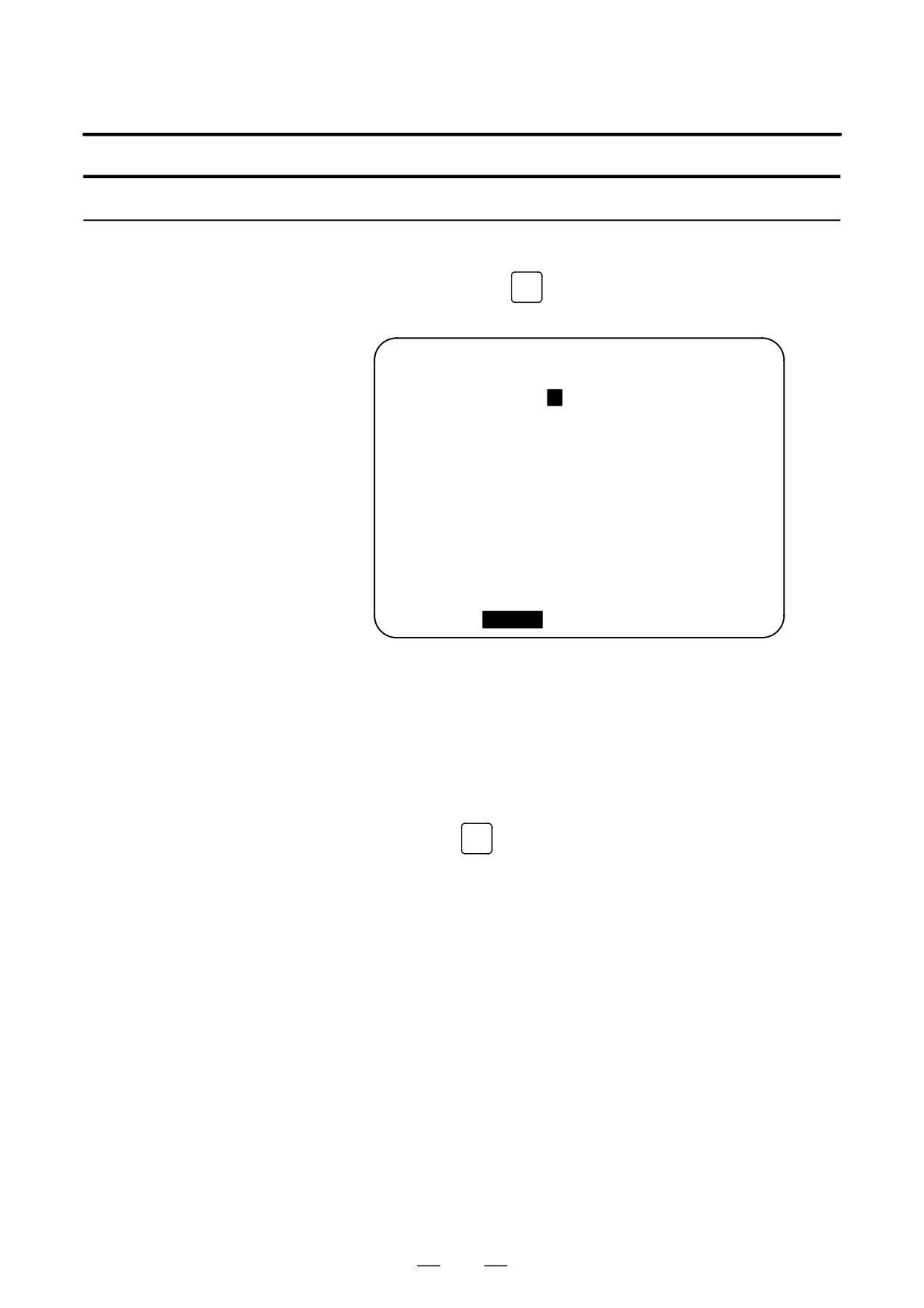
Procedure for enabling/displaying parameter writing
1
Select the MDI mode or enter state emergency stop.
OFFSET
2
Press function key
SETTING
3
Press soft key [SETING] to display the setting screen.
SETTING (HANDY)
O0001 N00000
PARAMETER WRITE =
1
(0:DISABLE 1:ENABLE)
TV CHECK
= 0 (0:OFF
1:ON)
PUNCH CODE
= 1 (0:EIA
1:ISO)
INPUT UNIT
= 0 (0:MM
1:INCH)
I/O CHANNEL
=
0 (0-3:CHANNEL NO.)
SEQUENCE NO.
= 0 (0:OFF
1:ON)
TAPE FORMAT
= 0 (0:NO CNV
1:F10/11)
SEQUENCE STOP
=
0 (PROGRAM NO.)
SEQUENCE STOP
=
11 (SEQUENCE NO.)
> _
S
0 T0000
MDI **** *** ***
16:05:59
[ OFFSET ][
SETING
][ WORK ][
][ (OPRT) ]
4
Move the cursor to PARAMETER WRITE using cursor keys.
5
Press soft key [(OPRT)], then press [1: ON] to enable parameter
writing.
At this time, the CNC enters the P/S alarm state (No. 100).
6
After setting parameters, return to the setting screen. Move the cursor
to PARAMETER WRITE and press soft key [(OPRT)] , then press
[0: OFF].
7
Depress the
RESET
key to release the alarm condition. If P/S alarm No.
000 has occurred, however, turn off the power supply and then turn it
on, otherwise the P/S alarm is not released.
Explanations
D Setting parameters with
See Chapter 8 for setting parameters with external input/output devices
external input/output
such as the Handy File.
devices
D Parameters that require
Some parameters are not effective until the power is turned off and on
turning off the power
again after they are set. Setting such parameters causes alarm 000. In this
case, turn off the power, then turn it on again.
D Parameter list
Refer to the FANUC Series 16i/18i/160i/180i-MODEL A Parameter
Manual (B-63010EN) for the parameter list.
D Setting data
Some parameters can be set on the setting screen if the parameter list
indicates “Setting entry is acceptable”. Setting 1 for PARAMETER
WRITE is not necessary when three parameters are set on the setting
screen.
778
B-63524EN/01
OPERATION
11. SETTING AND DISPLAYING DATA
11.5.2
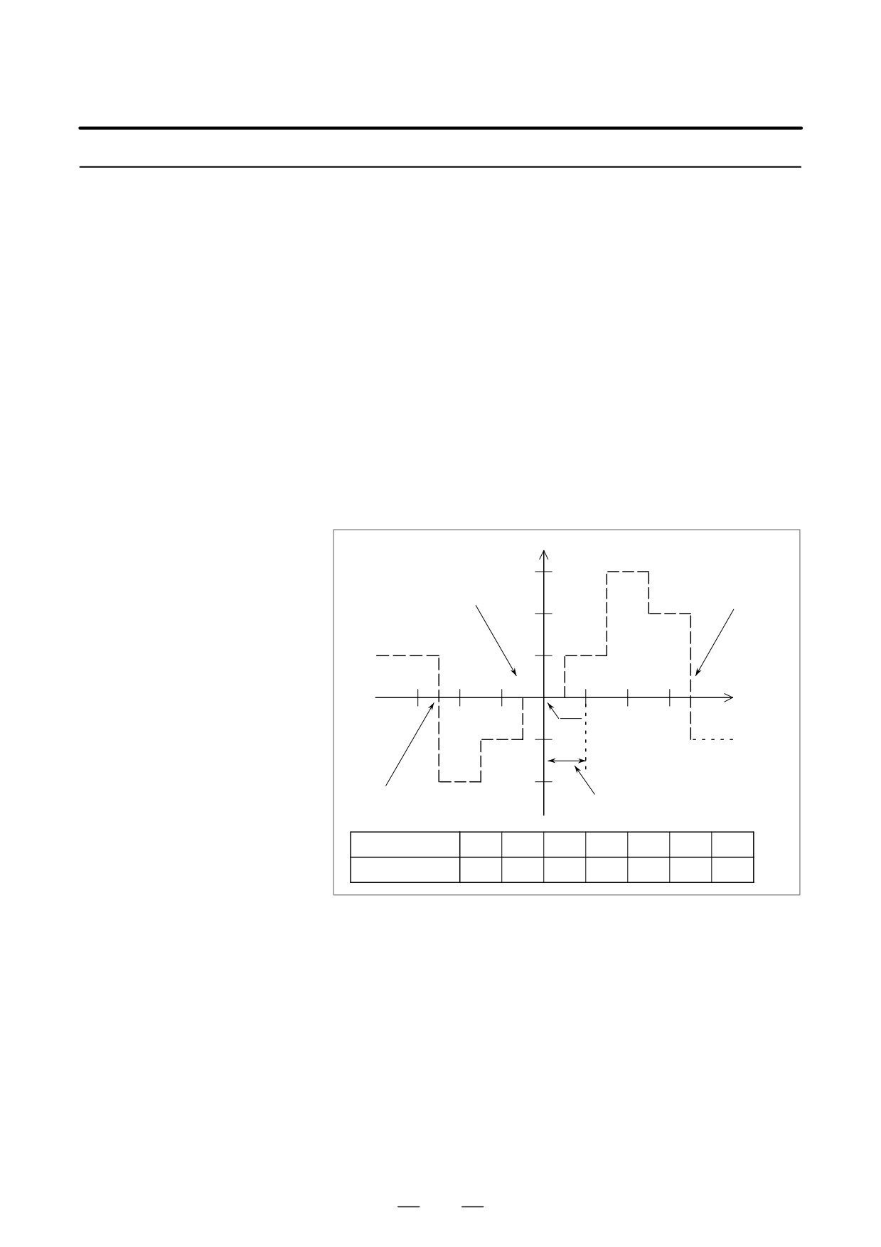
If pitch error compensation data is specified, pitch errors of each axis can
be compensated in detection unit per axis.
Displaying and Setting
Pitch error compensation data is set for each compensation point at the
Pitch Error
intervals specified for each axis. The origin of compensation is the
Compensation Data
reference position to which the tool is returned.
The pitch error compensation data is set according to the characteristics
of the machine connected to the NC. The content of this data varies
according to the machine model. If it is changed, the machine accuracy
is reduced.
In principle, the end user must not alter this data.
Pitch error compensation data can be set with external devices such as the
Handy File (see Chapter III-9). Compensation data can also be written
directly with the MDI panel.
The following parameters must be set for pitch error compensation. Set
the pitch error compensation value for each pitch error compensation
point number set by these parameters.
In the following example, 33 is set for the pitch error compensation point
at the reference position.
Pitch error compensation value (absolute value)
Compensation number pa-
3
rameter for the compensa-
Compensation number parameter
tion point having the largest
for the reference position (No.
value (No. 3622)
3620)
2
1
31
32
33
34
35
36
37
Reference posi-
-1
tion
Compensationmagnification
parameter (No. 3623)
-2
Compensation number parameter
Compensation interval
for the compensation point having
the smallest value (No. 3621)
parameter (No. 3624)
Compensation
31
32
33
34
35
36
37
position number
Compensation
+3
-1
-1
+1
+2
-1
-3
value to be set
D Number of the pitch error compensation point at the reference position
(for each axis): Parameter 3620
D Number of the pitch error compensation point having the smallest
value (for each axis): Parameter 3621
D Number of the pitch error compensation point having the largest value
(for each axis): Parameter 3622
D Pitch error compensation magnification (for each axis): Parameter
3623
D Interval of the pitch error compensation points (for each axis):
Parameter 3624
D Travel distance per revolution of pitch error compensation of the
rotary axis type (for each axis): Parameter 3625
779

11. SETTING AND DISPLAYING DATA
OPERATION
B-63524EN/01
Bidirectional pitch error
The bidirectional pitch error compensation function allows independent
compensation
pitch error compensation in different travel directions. (When the movement
is reversed, compensation is automatically carried out as in a backlash.)
To use this function, specify pitch error compensation for each travel
direction, that is, separately for the positive and negative directions of a
movement.
When using bidirectional pitch error compensation (setting the BDP bit
(bit 0 of parameter 3605) to 1), specify the following parameters in
addition to the pitch error compensation parameter.
D Number of the pitch error compensation point at the negative end (for
travel in the positive direction, for each axis): Parameter 3621
D Number of the pitch error compensation point at the positive end (for
travel in the positive direction, for each axis): Parameter 3622
D Number of the pitch error compensation point at the negative end (for
travel in the negative direction, for each axis): Parameter 3626
D Number of the pitch error compensation point at the positive end (for
travel in the negative direction, for each axis): Parameter 3627
Procedure for displaying and setting the pitch error compensation data
1
Set the following parameters:
D Number of the pitch error compensation point at the reference
position (for each axis): Parameter 3620
D Number of the pitch error compensation point having the smallest
value (for each axis): Parameter 3621
D Number of the pitch error compensation point having the largest
value (for each axis): Parameter 3622
D Pitch error compensation magnification (for each axis): Parameter
3623
D Interval of the pitch error compensation points (for each axis):
Parameter 3624
D Travel distance per revolution of pitch error compensation of the
rotary axis type (for each axis): Parameter 3625
When using bidirectional pitch error compensation (setting the BDP bit
(bit 0 of parameter 3605) to 1), specify the following parameters in
addition to the pitch error compensation parameter.
D Number of the pitch error compensation point at the negative end (for
travel in the positive direction, for each axis): Parameter 3621
D Number of the pitch error compensation point at the positive end (for
travel in the positive direction, for each axis): Parameter 3622
D Number of the pitch error compensation point at the negative end (for
travel in the negative direction, for each axis): Parameter 3626
D Number of the pitch error compensation point at the positive end (for
travel in the negative direction, for each axis): Parameter 3627
780
B-63524EN/01
OPERATION
11. SETTING AND DISPLAYING DATA
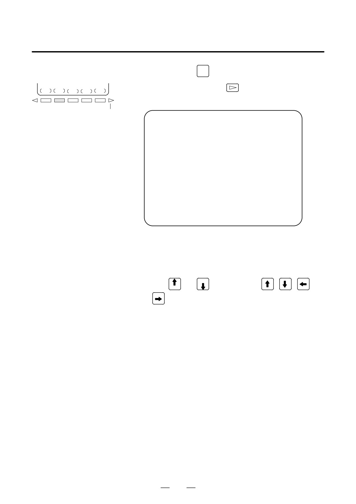
SYSTEM
2
Press function key
3
Press the continuous menu key
, then press chapter selection soft
PITCH
key [PITCH].
The following screen is displayed:
Continuous menu key
PIT-ERROR SETTING
O0000 N00000
NO. DATA
NO. DATA
NO. DATA
0000 0
0010 0
0020 0
0001 0
0011 0
0021 0
0002 0
0012 0
0022 0
0003 0
0013 0
0023 0
(X)
0004 0
0014 0
0024 0
0005 0
0015 0
0025 0
0006 0
0016 0
0026 0
0007 0
0017 0
0027 0
0008 0
0018 0
0028 0
0009 0
0019 0
0029 0
> _
MEM **** *** ***
16:05:59
[ NO.SRH ][ ON:1 ][ OFF:0 ][ +INPUT ][ -INPUT ]
4
Move the cursor to the compensation point number to be set in either
of the following ways:
D Enter the compensation point number and press the [NO.SRH] soft
key.
D Move the cursor to the compensation point number using the page
keys,
and PAGE
, and cursor keys,
,
,
, and
PAGE
5
Enter a value with numeric keys and press the [INPUT] soft key.
781
11. SETTING AND DISPLAYING DATA
OPERATION
B-63524EN/01
The program number, sequence number, and current CNC status are
11.6
always displayed on the screen except when the power is turned on, a
DISPLAYING THE
system alarm occurs, or the PMC screen is displayed.
PROGRAM NUMBER,
If data setting or the input/output operation is incorrect, the CNC does not
SEQUENCE
accept the operation and displays a warning message.
This section describes the display of the program number, sequence
NUMBER, AND
number, and status, and warning messages displayed for incorrect data
STATUS, AND
setting or input/output operation.
WARNING
MESSAGES FOR
DATA SETTING OR
INPUT/OUTPUT
OPERATION
11.6.1
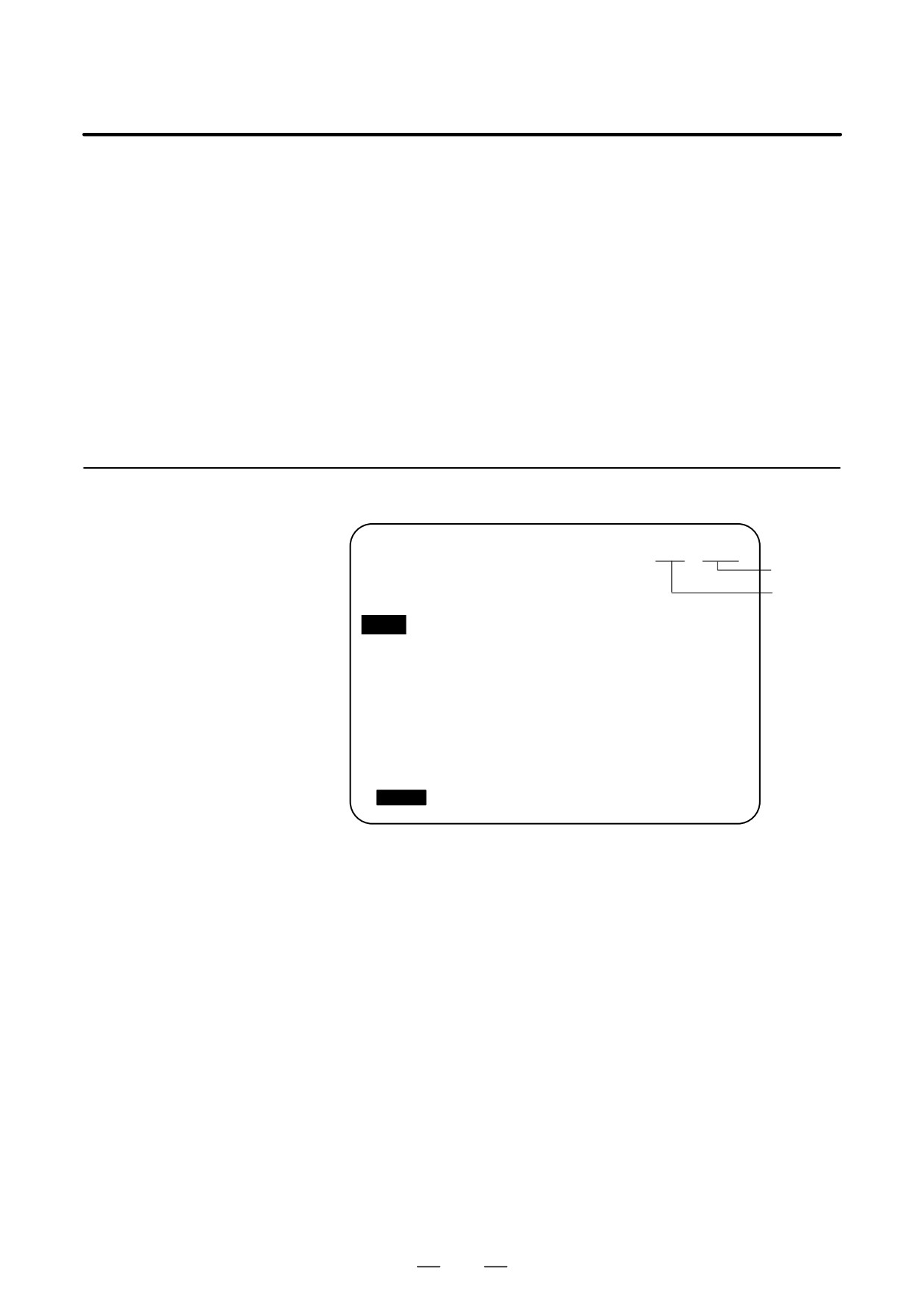
The program number and sequence number are displayed at the top right
on the screen as shown below.
Displaying the
Program Number and
PROGRAM
O2000 N00130
Sequence Number
Sequence No.
O1000
N100 G50 X0 Z0. ;
Program No.
N101 G00 X100. Z50. ;;
N102 G01 X230. Z56. ;
N103 W-10. ;
N104 U-120. ;
N105 M02 ;
> _
EDIT **** *** ***
16:05:59
[
PRGRM
][ CHECK ][ CURRNT ][ NEXT ][ (OPRT) ]
The program number and sequence number displayed depend on the
screen and are given below:
On the program screen in the EDIT mode on Background edit screen:
The program No. being edited and the sequence number just prior to
the cursor are indicated.
Other than above screens :
The program No. and the sequence No. executed last are indicated.
Immediately after program number search or sequence number
search :
Immediately after the program No. search and sequence No. search,
the program No. and the sequence No. searched are indicated.
782
B-63524EN/01
OPERATION
11. SETTING AND DISPLAYING DATA
11.6.2
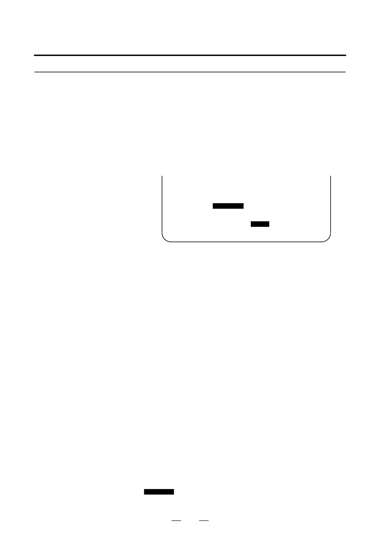
The current mode, automatic operation state, alarm state, and program
editing state are displayed on the next to last line on the CRT screen
Displaying the Status
allowing the operator to readily understand the operation condition of the
and Warning for Data
system.
Setting or Input/Output
If data setting or the input/output operation is incorrect, the CNC does not
Operation
accept the operation and a warning message is displayed on the next to last
line of the CRT screen. This prevents invalid data setting and input/output
errors.
Explanations
D Description of each
display
(9) Data is out of range.
(Note) Actually, this is displayed in the area starting
from (2).
(5)
(Note) Actually, 5 is displayed
--EMG--
in the area for (3) and (4).
(1)
(2)
(3)
(4)
(6)
(7)
(8)
EDIT STOP MTN FIN ALM hh:mm:ss INPUT
(10)
(Display soft keys)
HEAD1
Note) Actually, (10) is displayed at the position where (8) is now
displayed.
(1)
Current mode
MDI
:
Manual data input, MDI operation
MEM : Automatic operation (Memory operation)
RMT
:
Automatic operation (DNC operation)
EDIT
:
Memory editing
HND
:
Manual handle feed
JOG
:
Jog feed
TJOG : TEACH IN JOG
THND : TEACH IN HANDLE
INC
:
Manual incremental feed
REF
:
Manual reference position return
(2)
Automatic operation
****
:
Reset (When the power is turned on or the state in which
status
program execution has terminated and automatic operation has
terminated.
STOP : Automatic operation stop (The state in which one block has
been executed and automatic operation is stopped.)
HOLD : Feed hold (The state in which execution of one block has been
interrupted and automatic operation is stopped.)
STRT : Automatic operation start-up (The state in which the system
operates automatically)
(3)
Axis moving
MTN
:
Indicates that the axis is moving.
status/dwell status
DWL
:
Indicates the dwell state.
***
:
Indicates a state other than the above.
(4)
State in which an
FIN
:
Indicates the state in which an auxiliary function is being
auxiliary function is
executed. (Waiting for the complete signal from the PMC)
being executed
***
:
Indicates a state other than the above.
(5)
Emergency stop or
--EMG--
: Indicates emergency stop.(Blinks in reversed display.)
reset status
--RESET-- : Indicates that the reset signal is being received.
783
11. SETTING AND DISPLAYING DATA
OPERATION
B-63524EN/01
(6)
Alarm status
ALM
: Indicates that an alarm is issued. (Blinks in reversed display.)
BAT
: Indicates that the battery is low. (Blinks in reversed display.)
Space
: Indicates a state other than the above.
(7)
Current time
hh:mm:ss - Hours, minutes, and seconds
(8)
Program editing
INPUT
: Indicates that data is being input.
status
OUTPUT : Indicates that data is being output.
SRCH
: Indicates that a search is being performed.
EDIT
: Indicates that another editing operation is being performed
(insertion, modification, etc.)
LSK
: Indicates that labels are skipped when data is input.
RSTR
: Indicates that the program is being restarted
Space
: Indicates that no editing operation is being performed.
(9)
Warning for data
When invalid data is entered (wrong format, value out of range, etc.),
setting or input/
when input is disabled (wrong mode, write disabled, etc.), or when
output operation
input/output operation is incorrect (wrong mode, etc.), a warning message
is displayed. In this case, the CNC does not accept the setting or
input/output operation.
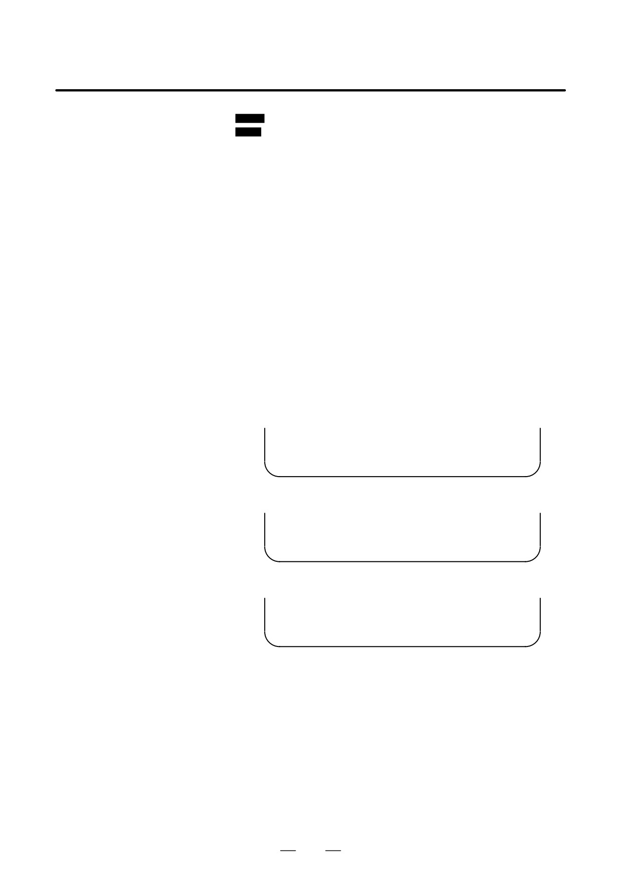
The following are examples of warning messages:
Example 1)
When a parameter is entered
> 1
EDIT WRONG MODE
(Display soft keys)
Example 2)
When a parameter is entered
> 999999999
MDI TOO MANY DIGITS
(Display soft keys)
Example 3)
When a parameter is output to an external input/output device
> _
MEM WRONG MODE
(Display soft keys)
(10) Tool post name
HEAD1 : Tool post 1 is selected.
(for the two-path
HEAD2 : Tool post 2 is selected.
control)
Other names can be used depending on the settings of parameters 3141
to 3147.
The tool post name is displayed at the position where (8) is now displayed.
While the program is edited, (8) is displayed.
784
B-63524EN/01
OPERATION
11. SETTING AND DISPLAYING DATA
By pressing the MESSAGE function key, data such as alarms, alarm
11.7
history data, and external messages can be displayed.
SCREENS DISPLAYED
For information relating to alarm display, see Section III.7.1. For
BY FUNCTION KEY
me
MESSAGE
information relating to alarm history display, see Section III.7.2.
For information relating to external message display, see the relevant
manual supplied by the machine tool builder.
External operator messages can be preserved as history data.
11.7.1
Preserved history data can be displayed on the external operator message
External Operator
history screen.
Message History
Display
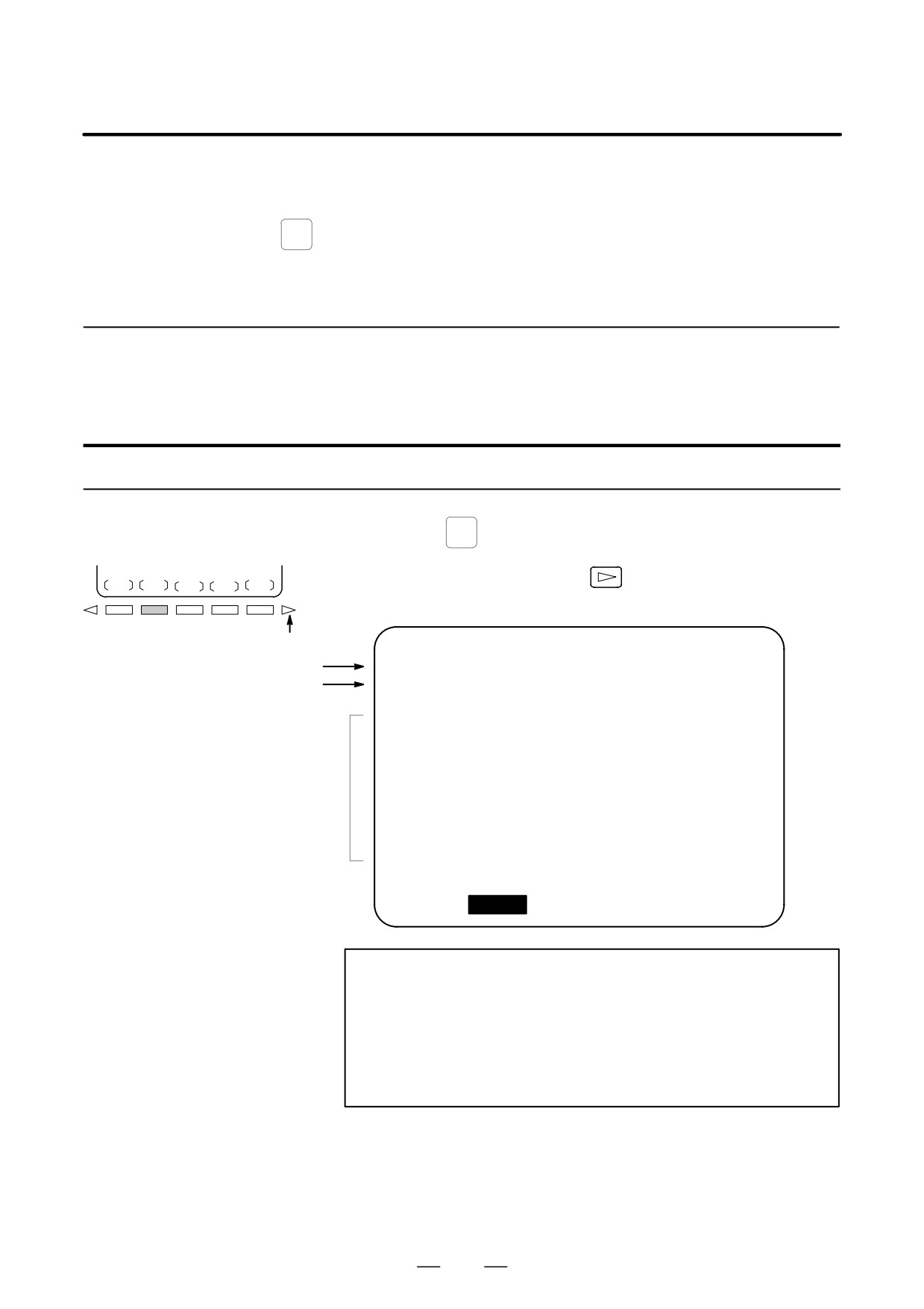
Procedure for external operator message history display
Procedure
1
Press the
MESSAGE
function key.
MSGHIS
2
Press the continuous menu key
, then press the chapter selection
soft key [MSGHIS]. The screen shown below appears.
Continuous menu key
MESSAGE HISTORY
O0000 N00000
Date and Page number
01/01/01 17:25:00
PAGE:1
Message nuumber
NO. ****
Display range
(Up to 255 characters)
MEM STRT MIN FIN ALM 09:36:48
[
][
MSGHIS
][ PUNCH ][
][ (OPRT) ]
NOTE
Up to 255 characters can be specified for an external
operator message. By setting MS1 and MS0 (bits 7 and 6
of parameter No. 3113), however, the number of characters
that can be preserved as external operator message history
data can be restricted, and the number of history data items
selected.
785
11. SETTING AND DISPLAYING DATA
OPERATION
B-63524EN/01
Explanations
D Updating external
When an external operator message number is specified, updating of the
operator message
external operator message history data is started; this updating is
history data
continued until a new external operator message number is specified or
deletion of the external operator message history data is specified.
D Clearing external
To clear external operator message history data, press the [CLEAR] soft
operator message
key. This clears all external operator message history data. (Set MSGCR
history data
(bit 0 of parameter No. 3113) to 1.)
Note that when MS1 and MS0 (bits 7 and 6 of parameter No. 3113), used
to specify the number of external operator message history data items to
be displayed, are changed, all existing external operator message history
data is cleared.
Limitations
D Two-path control
When two-path control is exercised, the external operator messages for
system 1 are displayed. (The external operator messages for system 2 are
not displayed.)
D Option
Before this function can be used, the external data input function or
optional external message function must be selected.
786

B-63524EN/01
OPERATION
11. SETTING AND DISPLAYING DATA
When screen indication isn’t necessary, the life of the back light for LCD
11.8
can be put off by turning off the back light.
CLEARING THE
The screen can be cleared by pressing specific keys. It is also possible to
SCREEN
specify the automatic clearing of the screen if no keys are pressed during
a period specified with a parameter.
But, the life of the back light may be contracted all the more when the
clearing of screen and re-indication of screen are repeated beyond the
necessity. This effect can be expected when a screen is cleared for more
than one hour.
11.8.1
Holding down the
CAN
key and pressing an arbitrary function key clears
Erase CRT Screen
the screen.
Display
Procedure for Erase CRT Screen Display
Procedure
D Clearing the screen
Hold down the
CAN
key and press an arbitrary function key (such as
POS
and
PROG
).
D Restoring the screen
Press an arbitrary function key.
787

11. SETTING AND DISPLAYING DATA
OPERATION
B-63524EN/01
11.8.2
The CNC screen is automatically cleared if no keys are pressed during the
period (in minutes) specified with a parameter. The screen is restored by
Automatic Erase CNC
pressing any key.
Screen Display
Procedure for Automatic Erase CRT Screen Display
D Clearing the screen
The CNC screen is cleared once the period (minutes) specified with
parameter No. 3123 has elapsed, provided the following conditions are
satisfied:
Conditions for clearing the CNC screen
D Parameter No. 3123 is set to other than 0.
D None of the following keys have been pressed:
MDI keys
Soft keys
External input keys
D No alarm has been issued.
D Restoring the screen
The cleared CNC screen is restored once at least one of the following
conditions is satisfied:
Conditions for restoring the CNC screen
D Any of the following keys has been pressed:
MDI keys
Soft keys
Externally input keys
D An alarm has been issued.
Some machines feature a special key for restoring the screen. For an
explanation of the location and use of this key, refer to the corresponding
manual, supplied by the machine tool builder.
Explanations
D Clearing the screen
If parameter No. 3123 is set to 0, clearing of the screen using the
CAN
key
using
CAN
+ function key
and a function key (III-11.8.1) is disabled.
D Specified period
The period specified with parameter No. 3123 is valid only for tool post
1.
D Alarm for another path
The screen is not cleared if an alarm is issued for tool post 1 or 2 or the
loader before the specified period elapses.
CAUTION
Pressing any key while the screen is being cleared restores
the screen. In such a case, however, the function assigned
to the pressed key is initiated. Do not press the
DELET
,
INSERT
ALTER
, or
key to restore the screen, therefore.
788