FANUC Series Series 16i-TB, Series 18i-TB, Series 160i-TB, Series 180i-TB. OPERATOR’S MANUAL - page 26
B-63524EN/01
OPERATION
11. SETTING AND DISPLAYING DATA
4
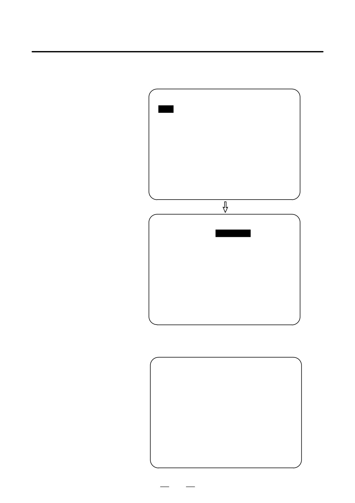
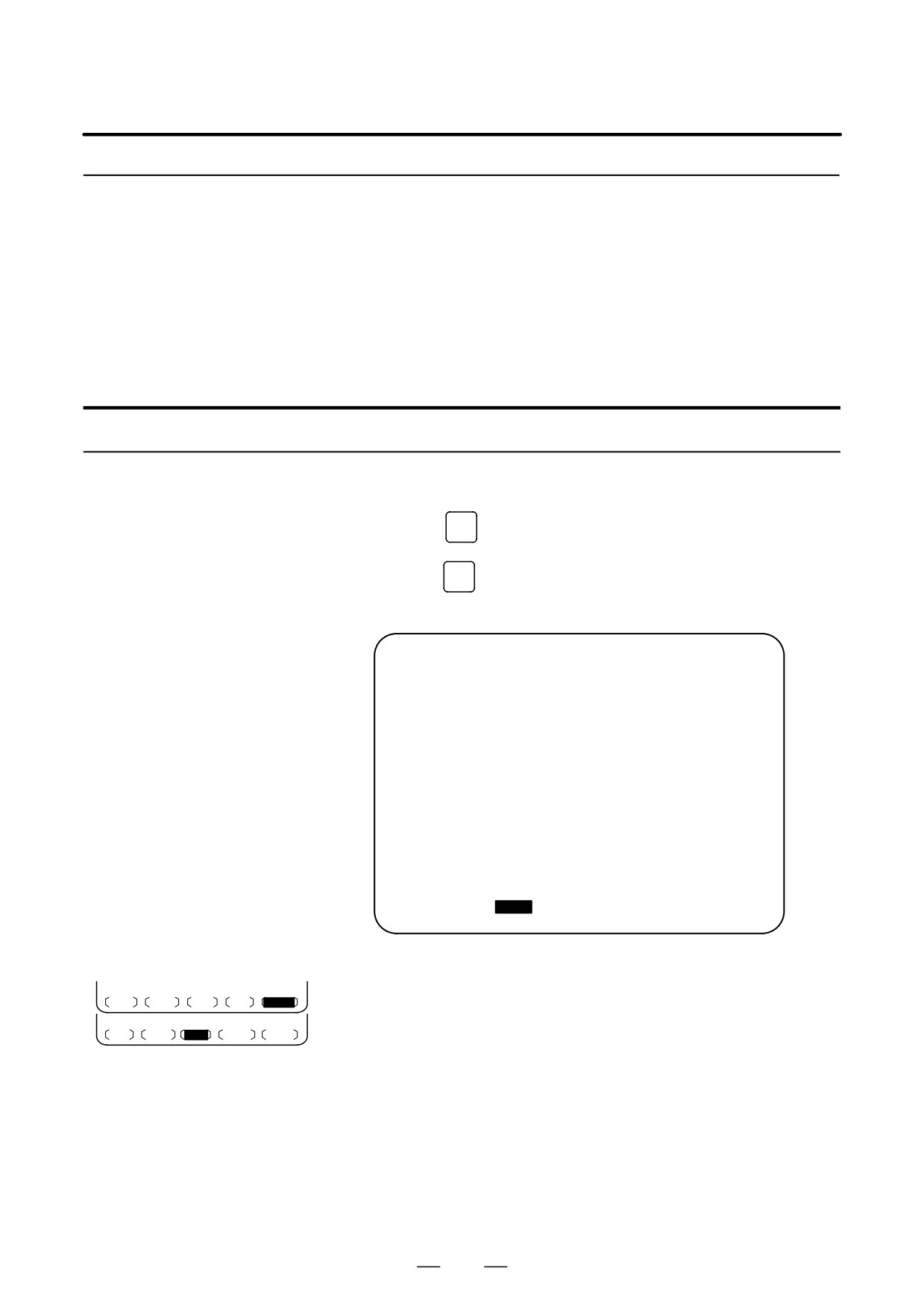
If a comment already exists in the block containing the program
number of a program whose machining time is to be inserted, the
machining time is inserted after the existing comment.
PROGRAM
O0100 N0000
O0100 (SHAFT XSF001) ;
N10 G92 X100. Z10. ;
N20 S1500 M03 ;
N30 G00 X20.5 Z5. T0101 ;
N40 G01 X-10. F25. ;
N50 G02 X16.5 Z-12. R2. ;
N60 G01 X40. ;
N70 X42. Z-13. ;
N80 Z-50. ;
N90 X44. Z-51. ;
N100 X80. ;
EDIT
*** *** *** ***
16:52:13
[ INS-TM
][
][
][
][
]
PROGRAM
O0100 N0000
O0100 (SHAFT XSF001)(001H20M01S) ;
N10 G92 X100. Z10. ;
N20 S1500 M03 ;
N30 G00 X20.5 Z5. T0101 ;
N40 G01 Z-10. F25. ;
N50 G02 X16.5 Z-12. R2. ;
N60 G01 X40. ;
N70 X42. Z-13. ;
N80 Z-50. ;
N90 X44. Z-51. ;
N100 X80. ;
EDIT
*** *** *** ***
16:52:13
[ INS-TM
][
][
][
][
]
5
The machining time of a program inserted as a comment can be
displayed after an existing program comment on the program
directory screen.
PROGRAM DIRECTORY
O0001 N00010
PROGRAM(NUM.)
MEMORY(CHAR.)
USED:
60
3321
FREE:
2
429
O0020
(GEAR XGR001 ):(012H48M01S)
O0002
(GEAR XGR002 ):(000H48M01S)
O0010
(BOLT YBT001 ):(004H16M01S)
O0020
(BOLT YBT002 ):(000H16M01S)
O0040
(SHAFT XSF001
):(001H20M01S)
O0050
(SHAFT XSF002
):(002H08M01S)
O0100
(SHAFT XSF011
):(002H32M02S)
O0200
(PLATE XPL100
):(000H51M01S)
>_
EDIT **** *** ***
14:46:09
[ PRGRM ][ DIR
][
][
][ (OPRT) ]
729
11. SETTING AND DISPLAYING DATA
OPERATION
B-63524EN/01
Explanations
D Machining time
Machining time is counted from the initial start after a reset in memory
operation mode to the next reset. If a reset does not occur during
operation, machining time is counted from the start to M03 (or M30).
However, note that the time during which operation is held is not counted,
but the time used to wait for completion of M, S, T, and/or B functions
is counted.
D Stamping the machining
The displayed machining time can be inserted (stamped) as a comment
time
in a program stored in memory. Machining time is inserted as a comment
after the program number.
D Program directory
The machining time inserted after a program number can be displayed on
the program directory screen by setting bit 0 (NAM) of parameter No.
3107 to 1. This lets the user know the machining time of each program.
This information is useful as reference data when planning processing.
Restrictions
D Alarm
When program execution is terminated by an alarm during the machining
time count, the machining time until the alarm is released is counted.
D M02
If the user specifies that M02 does not reset the CNC but returns
completion signal FIN to the CNC to restart the program from the
beginning successively (with bit 5 (M02) of parameter No. 3404 set to 0),
the machining time count stops when M02 returns completion signal FIN.
D Stamping the machining
When the machining time of a program to be stamped is not displayed on
time
the machining time display screen, the machining time cannot be inserted
into the program even if soft key [INS-TM] is pressed.
730
B-63524EN/01
OPERATION
11. SETTING AND DISPLAYING DATA
D Program directory
When the machining time inserted into a program is displayed on the
program directory screen and the comment after the program number
consists of only machining time data, the machining time is displayed in
both the program name display field and machining time display field.
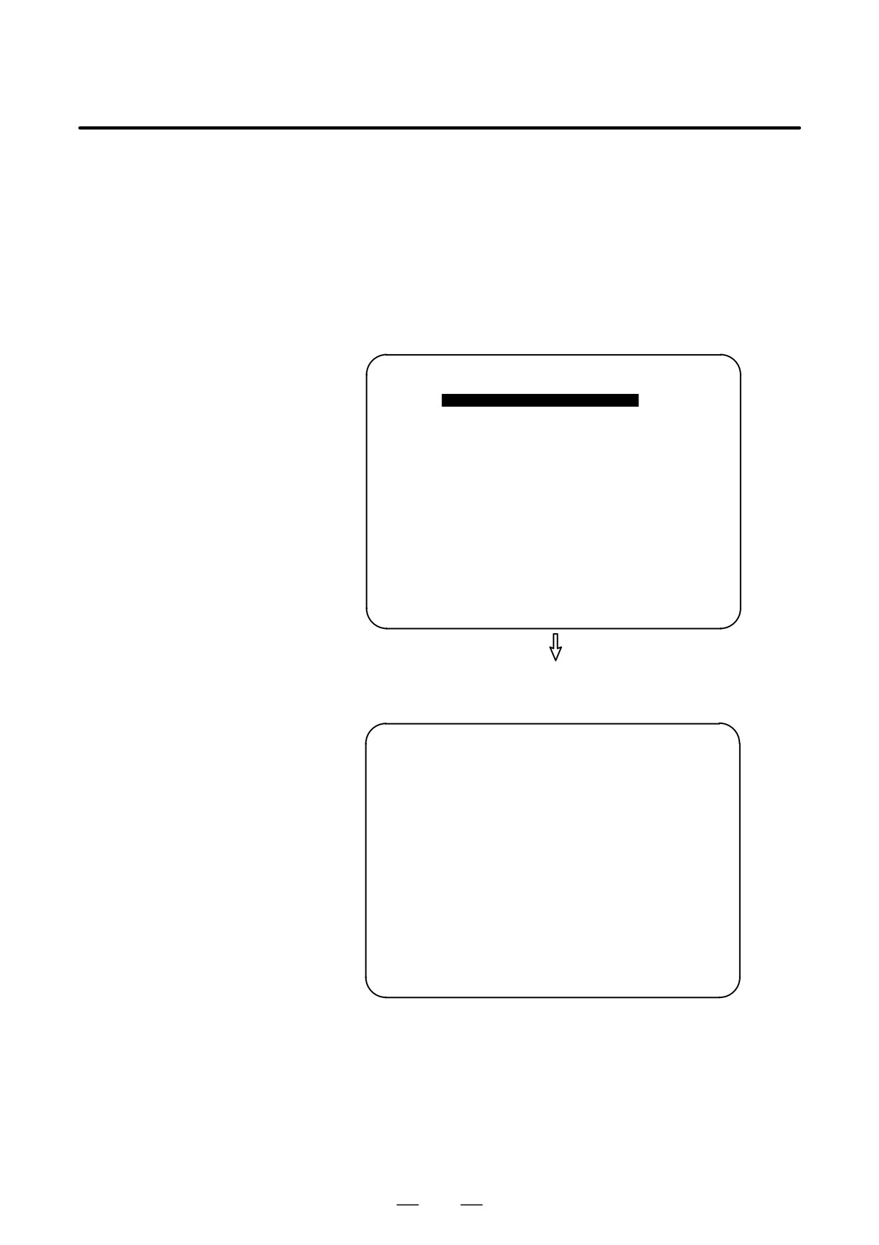
If machining time data is inserted into a program as shown below, the
program directory screen does not display the data or displays only part
of the data.
Example 1: Program directory screen when a program name
longer than 16 characters
PROGRAM
O0100 N0000
O0240 (SHAFT XSF301 MATERIAL=FC25)
(001H20M01S);
N10 G92 X100. Z10. ;
N20 S1500 M03 ;
N30 G00 X20.5 Z5. T0101 ;
N40 G01 Z-10. F25. ;
N50 G02 X16.5 Z-12. R2. ;
N60 G01 X40. ;
N70 X42. Z-13. ;
N80 Z-50. ;
N90 X44. Z-51. ;
EDIT
*** *** *** ***
16:52:13
[ INS-TM
][
][
][
][
]
All characters after the first 16 characters of the
program comment are discarded and the machining time
display field is left blank.
PROGRAM DIRECTORY
O0001 N00010
PROGRAM(NUM.)
MEMORY(CHAR.)
USED:
60
3321
FREE:
2
429
O0240
(SHAFT XSF301
):(
)
>_
EDIT **** *** ***
16:52:13
[ PRGRM ][ DIR
][
][
][ (OPRT) ]
731
11. SETTING AND DISPLAYING DATA
OPERATION
B-63524EN/01
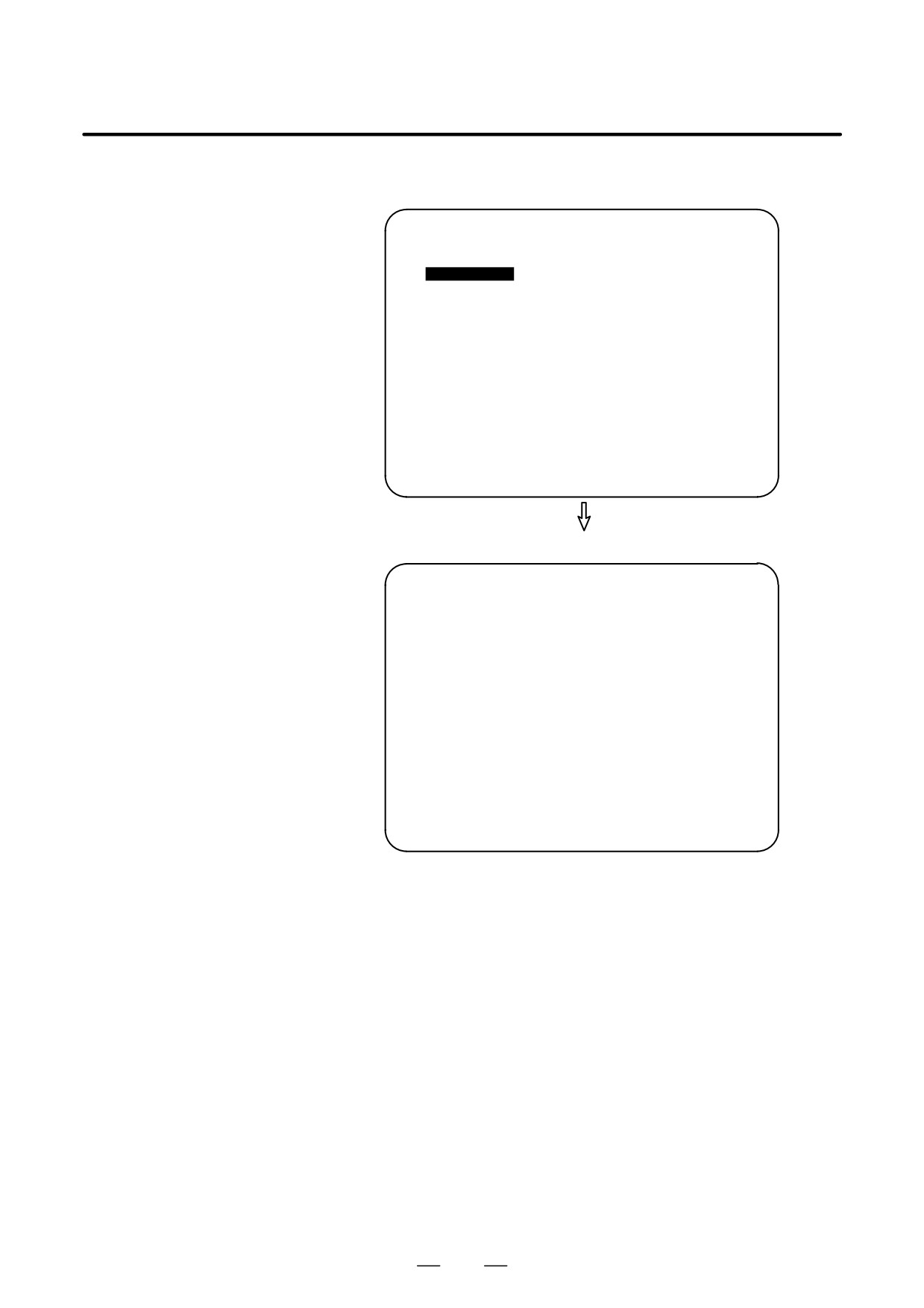
Example 2: Program directory screen when two or more machining
times are stamped.
PROGRAM
O0260 N0000
O0260 (SHAFT XSF302) (001H15M59S)
(001H20M01S) ;
N10 G92 X100. Z10. ;
N20 S1500 M03 ;
N30 G00 X20.5 Z5. T0101 ;
N40 G01 Z-10. F25. ;
N50 G02 X16.5 Z-12. R2. ;
N60 G01 X40. ;
N70 X42. Z-13. ;
N80 Z-50. ;
N90 X44. Z-51. ;
EDIT
*** *** *** ***
16:52:13
[ INS-TM
][
][
][
][
]
Only the first machining time is displayed.
PROGRAM DIRECTORY
O0001 N00010
PROGRAM(NUM.)
MEMORY(CHAR.)
USED:
60
3321
FREE:
2
429
O0260
(SHAFT XSF302
):(001H15M59S)
>_
EDIT **** *** ***
16:52:13
[ PRGRM ][ DIR
][
][
][ (OPRT) ]
732
B-63524EN/01
OPERATION
11. SETTING AND DISPLAYING DATA
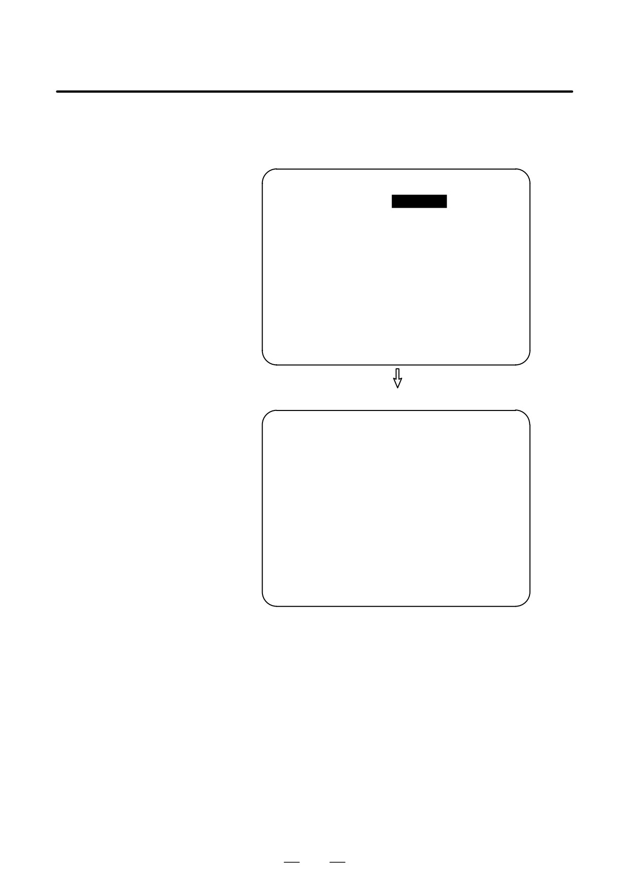
Example 3: Program directory screen when inserted machining time data
does not conform to the format hhhHmmMssS (3-digit
number followed by H, 2-digit number followed by M, and
2-digit number followed by S, in this order)
PROGRAM
O0280 N0000
O0280 (SHAFT XSF303) (1H10M59S)
N10 G92 X100. Z10. ;
N20 S1500 M03 ;
N30 G00 X20.5 Z5. T0101 ;
N40 G01 Z-10. F25. ;
N50 G02 X16.5 Z-12. R2. ;
N60 G01 X40. ;
N70 X42. Z-13. ;
N80 Z-50. ;
N90 X44. Z-51. ;
N100 X80. ;
EDIT
*** *** *** ***
16:52:13
[ INS-TM
][
][
][
][
]
The machining time display field is blank.
PROGRAM DIRECTORY
O0001 N00010
PROGRAM(NUM.)
MEMORY(CHAR.)
USED:
60
3321
FREE:
2
429
O0260
(SHAFT XSF302
):(001H15M59S)
O0280
(SHAFT XSF303
):(
)
>_
EDIT **** *** ***
16:52:13
[ PRGRM ][ DIR
][
][
][ (OPRT) ]
D Correcting the
If an incorrect machining time is calculated (such as when a reset occurs
machining time
during program execution), reexecute the program to calculate the correct
machining time. If the machining time display screen displays multiple
programs with the same program number, select the machining time of the
latest program number for insertion into the program.
733

11. SETTING AND DISPLAYING DATA
OPERATION
B-63524EN/01
11.2.7
Displaying the B-axis
Operation State
Displaying the B-axis operation state
1
Press the
PROG
function key.
2
Press the [CHECK] chapter selection soft key.
3
Press the [B-DSP] chapter selection soft key. Then, the B-axis
operation state is displayed on the program check screen. The
command currently being executed and the next command are
displayed.
PROGRAM CHECK
O0001 N00001
M102 ;
G00 X10. Z20. ;
G01 X20. Z30. F1000 ;
G04 P1000 ;
(ABSOLUTE)
(B-AXIS)
G00
G95
G22
X
40.000 G01(CURR) G97
G21
G80
Z
40.000 B -200.000 G90
G40
G50
Y
0.000 F 0.1500
G69
G25
G67
B -125.994 G00(NEXT)
B 250.000
M
102
T
F
0.1000
S
ACT.F
0
SCAT
0S
0 T0000
MEM STRT *** FIN
21:20:05
[ ABS
][ REL
][
B.DSP
][
][ (OPRT) ]
734
B-63524EN/01
OPERATION
11. SETTING AND DISPLAYING DATA
This section describes the screens displayed by pressing function key
11.3
SCREENS DISPLAYED
PROG
in the EDIT mode. Function key
PROG
in the EDIT mode can
BY FUNCTION KEY PROG display the program editing screen and the program display screen
(displays memory used and a list of programs). Pressing function key
(IN THE EDIT MODE)
PROG
in the EDIT mode can also display the conversational graphics
programming screen and the floppy file directory screen. See Chapter 9,
10 for the program editing screen and conversational graphics
programming screen. See Chapter 8 for the floppy file directory screen.
735
11. SETTING AND DISPLAYING DATA
OPERATION
B-63524EN/01
11.3.1
Displays the number of registered programs, memory used, and a list of
registered programs.
Displaying Memory
Used and a List of
Programs
Procedure for displaying memory used and a list of programs
1
Select the EDIT mode.
For the two-path control, select the tool post for which a program is to
be displayed with the tool post selection switch.
2
Press function key
PROG
3
Press chapter selection soft key [LIB].
PROGRAM DIRECTORY
O0001 N00010
PROGRAM(NUM.)
MEMORY(CHAR.)
USED:
60
3321
FREE:
2
429
O0010 O0001 O0003 O0002 O0555 O0999
O0062 O0004 O0005 O1111 O0969 O6666
O0021 O1234 O0588 O0020 O0040
> _
MDI **** *** ***
16:05:59
[ PRGRM ][ DIR
][
][
][ (OPRT) ]
736
B-63524EN/01
OPERATION
11. SETTING AND DISPLAYING DATA
Explanations
D Details of memory used
PROGRAM NO. USED
PROGRAM NO. USED : The number of the programs registered
(including the subprograms)
FREE :
The number of programs which can be
registered additionally.
MEMORY AREA USED
MEMORY AREA USED : The capacity of the program memory in which
data is registered (indicated by the number of
characters).
FREE :
The capacity of the program memory which
can be used additionally (indicated by the
number of characters).
D Program library list
Program Nos. registered are indicated.
Also, the program name can be displayed in the program table by setting
parameter NAM (No. 3107#0) to 1.
PROGRAM DIRECTORY
O0001 N00010
PROGRAM(NUM.)
MEMORY(CHAR.)
USED:
60
3321
FREE:
2
429
O0001 (MACRO-GCODE.MAIN)
O0002 (MACRO-GCODE.SUB1)
O0010 (TEST-PROGRAM.ARTHMETIC NO.1)
O0020 (TEST-PROGRAM.F10-MACRO)
O0040 (TEST-PROGRAM.OFFSET)
O0050
O0100 (INCH/MM CONVERT CHECK NO.1)
O0200 (MACRO-MCODE.MAIN)
> _
EDIT **** *** ***
16:05:59
[ PRGRM ][ DIR
][
][
][ (OPRT) ]
Fig. 11.3.1 (a)
PROGRAM DIRECTORY
O0001 N00010
PROGRAM(NUM.)
MEMORY(CHAR.)
USED:
17
4320
FREE:
46
3960
O0001
360
1966-06-12
14:40
O0002
240
1966-06-12
14:55
O0010
420
1966-07-01
11:02
O0020
180
1966-08-14
09:40
O0040
1140
1966-03-25
28:40
O0050
60
1966-08-26
16:40
O0100
120
1966-04-30
13:11
> _
EDIT **** *** ***
16:52:13
[ PRGRM ][ DIR
][
][
][ (OPRT) ]
Fig. 11.3.1 (b)
737
11. SETTING AND DISPLAYING DATA
OPERATION
B-63524EN/01
D Program name
Always enter a program name between the control out and control in
codes immediately after the program number.
Up to 31 characters can be used for naming a program within the
parentheses. If 31 characters are exceeded, the exceeded characters are
not displayed.
Only program number is displayed for the program without any program
name.
f VVVV
(ffff…f)
;
Program number Program name (up to 31 characters)
D Software series
Software series of the system is displayed.
It is used for maintenance ; user is not required this information.
D Order in which programs
Programs are displayed in the same order that they are registered in the
are displayed in the
program library list. However, if bit 4 (SOR) of parameter 3107 is set to
program library list
1, programs are displayed in the order of program number starting from
the smallest one.
D Order in which programs
Immediately after all programs are cleared (by turning on the power while
are registered
pressing the
DELETE
key), each program is registered after the last program
in the list.
If some programs in the list were deleted, then a new program is
registered, the new program is inserted in the empty location in the list
created by the deleted programs.
Example) When bit 4 (SOR) of parameter 3107 is 0
1. After clearing all programs, register programs O0001, O0002, O0003,
O0004, and O0005 in this order. The program library list displays the
programs in the following order:
O0001, O0002, O0003, O0004, O0005
2. Delete O0002 and O0004. The program library list displays the
programs in the following order:
O0001, O0003, O0005
3. Register O0009. The program library list displays the programs in the
following order:
O0001, O0009, O0003, O0005
738
B-63524EN/01
OPERATION
11. SETTING AND DISPLAYING DATA
11.3.2
In two-path control, the programs for both tool posts can be displayed and
edited on the same screen when bit 0 (DHD) of parameter No. 3106 is set
Two-path
to 1.
Simultaneous Editing
The name of each tool post is displayed above the corresponding program.
on the Program Screen
Procedure for Two-path Simultaneous Editing on the Program Screen
1
Specify EDIT mode for both tool posts.
2
Press function
PROG
key.
Shared screen
(7 soft keys display unit)
PROGRAM
O1357 N00120
O2468 N00130
(HEAD1)
(HEAD2)
O1357 (HEAD-1 MAIN PROGRAM);O2468 (HEAD-2 MAIN PROGRAM);
N010 G90 G00 X200.0 Z220.0 ;N010 G90 G00 X200.0 Z220.0 ;
N020 T0101 ;
N020 T0101 ;
N030 S30000 M03 ;
N030 S30000 M03 ;
N040 G40 G00 X40.0 Z180.0 ;
N040 G41 G00 X40.0 Z180.0 ;
N050 G01 Z140.0 F1000.0 ;
N050 G01 Z140.0 F1000.0 ;
N060 X60.0 Z110.0 ;
N060 X60.0 Z110.0 ;
N070 Z90.0 ;
N070 Z90.0 ;
N080 X100.0 Z80.0 ;
N080 X100.0 Z80.0 ;
N090 Z60.0 ;
N090 Z60.0 ;
N100 X140.0 Z40.0 ;
N100 X140.0 Z40.0 ;
N110 X200.0 Z220.0 ;
N110 X200.0 Z220.0 ;
N120 S0 M05 ;
N120 T0100 ;
N130
T0102 ;
N140 S1000 ;
N150 G41 G00 X40.0 Z180.0 ;
>N130T0100;M30;
EDIT **** *** *** 16:05:59 HEAD1
[ BG-EDT ][ O SRH ][ SRH + ][ SRH - ][ REWIND ]
Shared screen
(12 soft keys display unit)
PROGRAM
O1234 N00010
O2345 N00100
(HEAD1)
(HEAD2)
O1234 ;
O2345;
N10
G00 ;
N100 G00 ;
N20
X100.0 ;
N200 X0 ;
N30
X200.0 ;
N300 X50.0 ;
N40
X300.0 Z300.0 ;
N400 M02 ;
N50
X400.0 ;
%
N60
X500.0 ;
N70
M02 ;
%
>_
EDIT STRT MIN FIN ALM 17:25:01 HEAD1
[
][
][
][
][
][
] [PRGRM][ LIB ][
][
][(OPR)][
]
739

11. SETTING AND DISPLAYING DATA
OPERATION
B-63524EN/01
Explanations
D Shared screen and
When the selected tool post is in EDIT mode, pressing the [PRGRM] soft
individual screen
key displays a shared screen which shows the program for the first tool
post on the left and that for the second tool post on the right. However,
if the tool post that is not selected fails to satisfy any of the conditions
described below, only the individual screen for the selected tool post is
displayed.
<Conditions>
• Bit 0 (DHD) of parameter No. 3106 is set to 1.
• The program screen for the selected tool post is the 12 soft keys display
unit
(when the 12 soft keys display unit is being used).
• Both tool posts are set to EDIT mode.
• Background editing is not specified for either tool post.
When the mode for the tool post that is not selected is changed from EDIT
mode on the shared screen, the individual screen (12 soft keys display unit
when 12 soft keys display unit is being used) for the selected tool post is
displayed.
On the 12 soft keys display unit, pressing the [PRGRM] soft key toggles
between the individual screen (7 soft keys display unit) and the shared
screen.
PROGRAM
O1357 N00130
O1357
(HEAD-1 MAIN PROGRAM) ;
N010
G90 G00 X200.0 Z220.0 ;
N020 T0101 ;
N030 S30000 M03 ;
N040 G40 G00 X40.0 Z180.0 ;
N050 G01 Z140.0 F1000.0 ;
N060 X60.0 Z110.0 ;
N070 Z90.0 ;
N080 X100.0 Z80.0 ;
N090 Z60.0 ;
N100 X140.0 Z40.0 ;
>_
EDIT **** *** ***
14:25:36
[ BG-EDT ][ O SRH ][ SRH↓ ][ SRH↑ ][ REWIND ]
740
B-63524EN/01
OPERATION
11. SETTING AND DISPLAYING DATA
Individual screen
(12 soft keys screen on the 12 soft
keys display unit)
PROGRAM
O1234 N00010
O1234 ;
N10 G00 ;
N20 X100.0 ;
N30 X200.0 ;
N40 X300.0 Z300.0 ;
N50 X400.0 ;
N60 X500.0 ;
N70 M02 ;
%
>_
EDIT STRT MIN FIN ALM 17:25:01 HEAD1
[
][
][
][
][
][
] [PRGRM][ LIB ][
][
][(OPR)][
]
Individual screen
(7 soft keys screen on the 12 soft
keys display unit)
ACTUAL POSITION
O1234 N00010
(ABSOLUTE)
(RELATIVE)
F
1000
MM/M
X
0.000
X
0.000
Y
0.000
Y
0.000
Z
0.000
Z
0.000
A
0.000
A
0.000
B
0.000
B
0.000
PROGRAM
O1234 N00010
O1234 ;
N10
G00 ;
N20
X100.;
(MACHINE)
N30
X200.;
X
0.000
N40
X300. Z300.;
Y
0.000
N50
X400.;
Z
0.000
N60
X500.;
A
0.000
N70
M02 ;
B
0.000
%
G00
G25
G97
G22
u_
G67
G80
G99
G67
G21
G54
G40
G18
SCAT
EDIT STRT MIN FIN ALM 17:25:01 HEAD1
[
][ABS][REL][ALL][
][
] [PRGRM][ LIB ][
][
][(OPR)][
]
D Editing operation
Editing is enabled only for the program for the selected tool post. The
program for the first or second tool post can be edited on the same screen
by selecting either tool post with the tool post selection signal.
D 7 soft keys display unit
On 7 soft keys display unit, the shared screen consists of 80 digits x 25
shared screen
lines. If the tool post name specified with parameter No. 3131 contains
a character other than alphanumeric and special characters (”# $ % & ’ ()
* + , - . / : ; < = > ? @ [ ¥ ] ^ _ and space), the character ! will not be
displayed correctly. In such a case, operation soft keys [SRH° ] and
[SRH± ] are displayed as [SRH +] and [SRH -].
Limitations
This function cannot be used for background editing.
741
11. SETTING AND DISPLAYING DATA
OPERATION
B-63524EN/01
11.3.3
In addition to the normal listing of the numbers and names of CNC
programs stored in memory, programs can be listed in units of groups,
Displaying a Program
according to the product to be machined, for example.
List for a Specified
Group
To assign CNC programs to the same group, assign names to those
programs, beginning each name with the same character string.
By searching through the program names for a specified character string,
the program numbers and names of all the programs having names
including that string are listed.
Procedure for Displaying a Program List for a Specified Group
Procedure
1
Enter EDIT or background editing mode.
2
Press the
PROG
function key.
3
Press the
PROG
function key or [DIR] soft key to display the program
list.
PROGRAM DIRECTORY
O0001 N00010
PROGRAM (NUM.) MEMORY (CHAR.)
USED:
60
3321
FREE:
2
429
O0020
(GEAR-1000 MAIN)
O0040
(GEAR-1000 SUB-1)
O0060
(SHAFT-2000 MAIN)
O0100
(SHAFT-2000 SUB-1)
O0200
(GEAR-1000 SUB-2)
O1000
(FRANGE-3000 MAIN)
O2000
(GEAR-1000 SUB-3)
O3000
(SHAFT-2000 SUB-2)
> _
EDIT **** *** *** ***
16:52:13
[ PRGRM ]
[
DIR
]
[
]
[
]
[
(OPRT) ]
4
Press the [(OPRT)] operation soft key.
BG-EDT O-SRH
GROUP
5
Press the [GROUP] operation soft key.
(NAME) PR-GRP
6
Press the [NAME] operation soft key.
7
Enter the character string corresponding to the group for which a
search is to be made, using the MDI keys. No restrictions are imposed
on the length of a program name. Note, however, that search is made
based on only the first 32 characters.
Example: To search for those CNC programs having names that
begin with character string “GEAR-1000,” enter the
following:
>GEAR-1000*_
742
B-63524EN/01
OPERATION
11. SETTING AND DISPLAYING DATA
8
Pressing the [EXEC] operation soft key displays the group-unit
EXEC
program list screen, listing all those programs whose name includes
the specified character string.
PROGRAM DIRECTORY (GROUP) O0001 N00010
PROGRAM (NUM.) MEMORY (CHAR.)
USED:
60
3321
FREE:
2
429
O0020
(GEAR-1000 MAIN)
O0040
(GEAR-1000 SUB-1)
O0200
(GEAR-1000 SUB-2)
O2000
(GEAR-1000 SUB-3)
> _
EDIT **** *** *** ***
16:52:25
[ PRGRM ]
[
DIR
]
[
]
[
]
[
(OPRT) ]
[Group-unit program list screen displayed
when a search is made for “GEAR-1000*”]
When the program list consists of two or more pages, the pages can be
changed by using a page key.
Explanations
D * and ?
In the above example, the asterisk (*) must not be omitted. The asterisk
indicates an arbitrary character string (wild card specification).
“GEAR-1000*” indicates that the first nine characters of the target
program names must be “GEAR-1000,” followed by an arbitrary
character string. If only “GEAR-1000” is entered, a search is made only
for those CNC programs having the nine-character name “GEAR-1000.”
A question mark (?) can be used to specify a single arbitrary character.
For example, entering “????-1000” enables a search to be made for
programs having names which start with four arbitrary characters,
followed by “-1000”.
743
11. SETTING AND DISPLAYING DATA
OPERATION
B-63524EN/01
[Example of using wild cards]
(Entered character string)
(Group for which the search will be made)
(a)
“*”
CNC programs having any name
(b)
“*ABC”
CNC programs having names which end
with “ABC”
(c)
“ABC*”
CNC programs having names which start
with “ABC”
(d)
“*ABC*”
CNC programs having names which
include “ABC”
(e)
“?A?C”
CNC programs having four-character
names, the second and fourth characters
of which are A and C, respectively
(f)
“??A?C”
CNC programs having five-character
names, the third and fifth characters of
which are A and C, respectively
(g)
“123*456”
CNC programs having names which start
with “123” and which end with “456”
D When the specified
If no program is located as a result of a search for an entered character
character string cannot
string, warning message “DATA NOT FOUND” is displayed on the
be found
program list screen.
D Holding the group for
A group-unit program list, generated by a search, is held until the power
which a search is made
is turned off or until another search is performed.
D Group for which
After changing the screen from the group-unit program list to another
previous search was
screen, pressing the [PR-GRP] operation soft key (displayed in step 6)
made
redisplays the group-unit program list screen, on which the program
names for the previously searched group are listed. Using this soft key
eliminates the need to enter the relevant character string again to redisplay
the search results after changing the screen.
Examples
Assume that the main programs and subprograms for machining gear part
number
1000 all have names which include character string
“GEAR-1000.” The numbers and names of those programs can be listed
by searching through the names of all CNC programs for character string
“GEAR-1000.” This function facilitates the management of the CNC
programs stored in large-capacity memory.
744
B-63524EN/01
OPERATION
11. SETTING AND DISPLAYING DATA
11.4
OFFSET
Press function key
SETTING
to display or set tool compensation values and
SCREENS DISPLAYED
other data.
FFSET
This section describes how to display or set the following data:
BY FUNCTION KEY
SETTING
1. Tool offset value
2. Settings
3. Run time and part count
4. Workpiece origin offset value or workpiece coordinate system shift
value
5. Custom macro common variables
6. Software operator’s panel
7. Tool life management data
This section also describes following functions.
D Direct input of tool offset value
D Direct input of tool offset value measured B
D Counter input of offset value
D Direct input of workpiece coordinate system shift
D Y axis offset
D Sequence number comparison and stop function
The following functions depend on the specifications of the machine tool
builder. See the manual issued by the machine tool builder for details.
D Direct input of tool offset value
D Direct input of tool offset value measured B
D Software operator’s panel
D Tool life management data
745
11. SETTING AND DISPLAYING DATA
OPERATION
B-63524EN/01
11.4.1
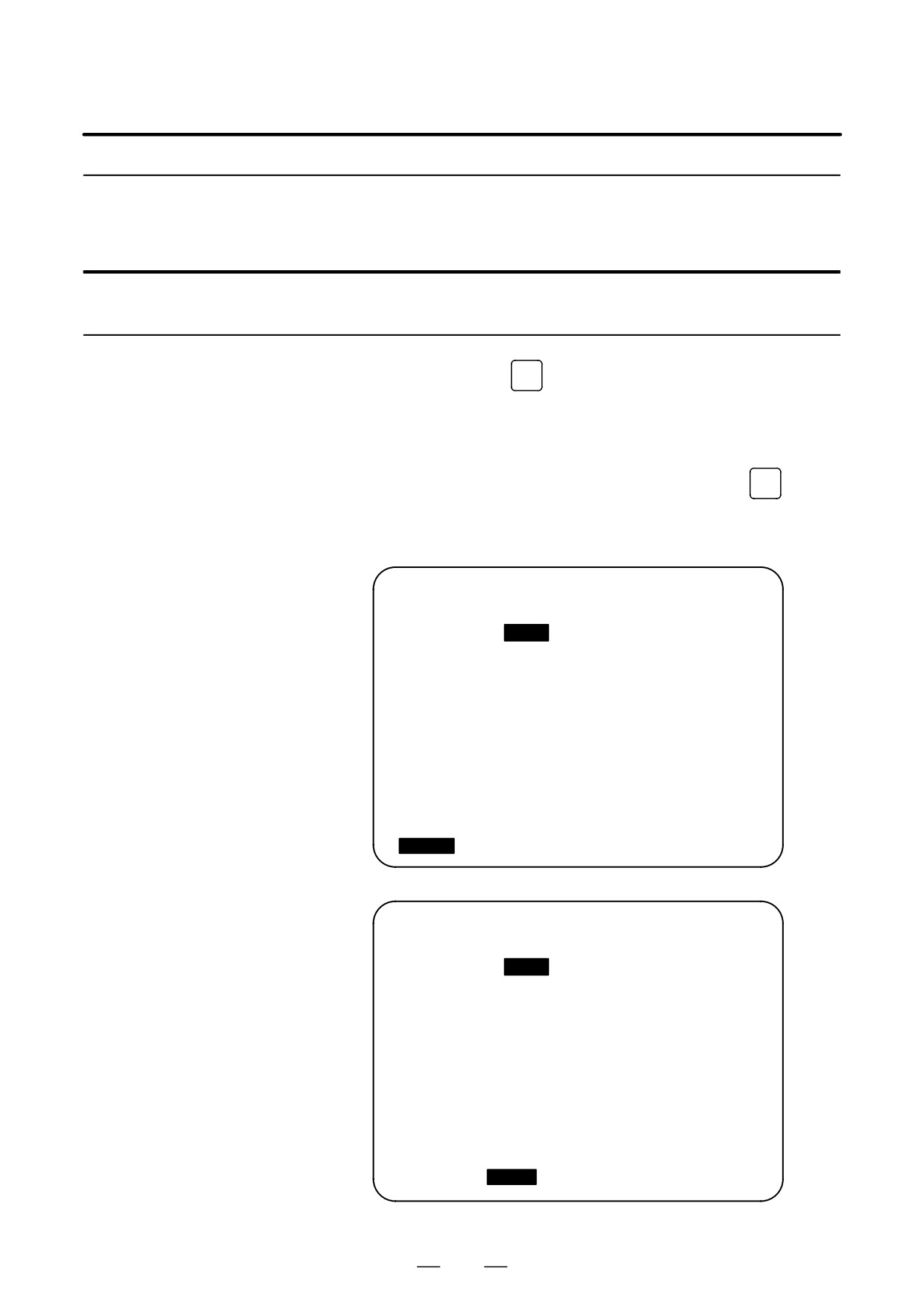
Dedicated screens are provided for displaying and setting tool offset
values and tool nose radius compensation values.
Setting and Displaying
the Tool Offset Value
Procedure for setting and displaying the tool offset value and the tool nose radius
compensation value
OFFSET
1
Press function key
SETTING
For the two-path control, select the tool post for which tool
compensation values are to be displayed with the tool post selection
switch.
OFFSET
2
Press chapter selection soft key [OFFSET] or press
SETTING
several
times until the tool compensation screen is displayed.
Different screens are displayed depending on whether tool geometry
offset, wear offset, or neither is applied.
OFFSET
O0001 N00000
NO.
X
Z.
R
T
001
0.000
10.000
0.000
0
002
0.000
0.000
0.000
0
003
0.000
0.000
0.000
0
004
40.000
-40.000
0.000
0
005
0.000
0.000
0.000
0
006
0.000
0.000
0.000
0
007
0.000
0.000
0.000
0
008
0.000
0.000
0.000
0
ACTUAL POSITION (RELATIVE)
U
101.000
W
202.094
> _
MDI **** *** ***
16:05:59
[
OFFSET ][ SETING ][ WORK ][
][ (OPRT) ]
Without tool geometry/wear offset
OFFSET/GEOMETRY
O0001 N00000
NO.
X
Z.
R
T
G 001
0.000
1.000
0.000
0
G 002
1.486
-49.561
0.000
0
G 003
1.486
-49.561
0.000
0
G 004
1.486
0.000
0.000
0
G 005
1.486
-49.561
0.000
0
G 006
1.486
-49.561
0.000
0
G 007
1.486
-49.561
0.000
0
G 008
1.486
-49.561
0.000
0
ACTUAL POSITION (RELATIVE)
U
101.000
W
202.094
> _
MDI **** *** ***
16:05:59
[ WEAR
][
GEOM
][ WORK ][
][ (OPRT) ]
With tool geometry offset
746
B-63524EN/01
OPERATION
11. SETTING AND DISPLAYING DATA
OFFSET/WEAR
O0001 N00000
NO.
X
Z.
R
T
W 001
0.000
1.000
0.000
0
W 002
1.486
-49.561
0.000
0
W 003
1.486
-49.561
0.000
0
W 004
1.486
0.000
0.000
0
W 005
1.486
-49.561
0.000
0
W 006
1.486
-49.561
0.000
0
W 007
1.486
-49.561
0.000
0
W 008
1.486
-49.561
0.000
0
ACTUAL POSITION (RELATIVE)
U
101.000
W
202.094
> _
MDI **** *** ***
16:05:59
[
WEAR
][ GEOM
][ WORK ][
][ (OPRT) ]
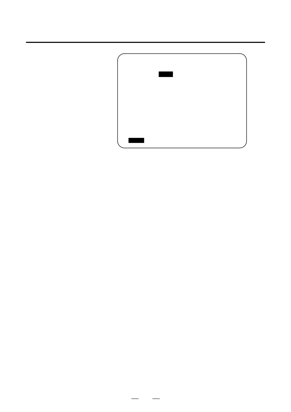
With tool wear offset
3
Move the cursor to the compensation value to be set or changed using
page keys and cursor keys, or enter the compensation number for the
compensation value to be set or changed and press soft key
[NO.SRH].
4
To set a compensation value, enter a value and press soft key [INPUT].
To change the compensation value, enter a value to add to the current
value (a negative value to reduce the current value) and press soft key
[+INPUT]. Or, enter a new value and press soft key [INPUT].
TIP is the number of the virtual tool tip (see Programming).
TIP may be specified on the geometry compensation screen or on the
wear compensation screen.
Explanations
D Decimal point input
A decimal point can be used when entering a compensation value.
D Other method
An external input/output device can be used to input or output a cutter
compensation value. See Chapter III-8.
Tool length compensation values can be set using the following functions
described in subsequent subsections: direct input of tool offset value,
direct-input function B for tool offset measured, and counter input of
offset value.
D Tool offset memory
16 groups are provided for tool compensation. The number of groups can
be optionally extended to 32, 64, or 99. For the two-path control, the
above number of groups can be used for each tool post. Tool geometry
compensation or wear compensation can be selected for each group.
747
11. SETTING AND DISPLAYING DATA
OPERATION
B-63524EN/01
D Disabling entry of
In some cases, tool wear compensation or tool geometry compensation
compensation values
values cannot be input because of the settings in bits 0 (WOF) and 1
(GOF) of parameter 3290. The input of tool compensation values from
the MDI can be inhibited for a specified range of offset numbers. The first
offset number for which the input of a value is inhibited is set in parameter
No. 3294. The number of offset numbers, starting from the specified first
number, for which the input of a value is inhibited is set in parameter No.
3295.
Consecutive input values are set as follows:
1) When values are input for offset numbers, starting from one for which
input is not inhibited to one for which input is inhibited, a warning is
issued and values are set only for those offset numbers for which input
is not inhibited.
2) When values are input for offset numbers, starting from one for which
input is inhibited to one for which input is not inhibited, a warning is
issued and no values are set.
D Displaying radius and
The radius and TIP are not displayed if the tool tip radius compensation
TIP
option is not displayed.
D Changing offset values
When offset values have been changed during automatic operation, bit 4
during automatic
(LGT) and bit 6 (LWM) of parameter 5002 can be used for specifying
operation
whether new offset values become valid in the next move command or in
the next T code command.
When geometry compensa-
When geometry compensa-
tion values and wear com-
tion values and wear com-
LGT
LWM
pensation values are sepa-
pensation values are not
rately specified
separately specified
Become valid in the next T
Become valid in the next T
0
0
code block
code block
Become valid in the next T
Become valid in the next T
1
0
code block
code block
Become valid in the next T
Become valid in the next move
0
1
code block
command
Become valid in the next move
Become valid in the next move
1
1
command
command
748
B-63524EN/01
OPERATION
11. SETTING AND DISPLAYING DATA
11.4.2
To set the difference between the tool reference position used in
programming (the nose of the standard tool, turret center, etc.) and the tool
Direct Input of Tool
tip position of a tool actually used as an offset value
Offset Value
Procedure for direct input of tool offset value
D Setting of Z axis offset
1
Cut surface A in manual mode with an actual tool.
value
Suppose that a workpiece coordinate system has been set.
X
ÇÇÇ
ÇÇÇ
Surface B
α
Z
Surface A
β
2
Release the tool in X-axis direction only, without moving Z-axis and
stop the spindle.
3
Measure distance β from the zero point in the workpiece coordinate
system to surface A.
Set this value as the measured value along the Z-axis for the desired
offset number, using the following procedure:
OFFSET/GEOMETRY
O0001 N00000
NO.
X
Z.
R
T
G 001
0.000
1.000
0.000
0
G 002
1.486
-49.561
0.000
0
G 003
1.486
-49.561
0.000
0
G 004
1.486
0.000
0.000
0
G 005
1.486
-49.561
0.000
0
G 006
1.486
-49.561
0.000
0
G 007
1.486
-49.561
0.000
0
G 008
1.486
-49.561
0.000
0
ACTUAL POSITION (RELATIVE)
U
0.000
W
0.000
V
0.000
H
0.000
>MZ120._
MDI **** *** ***
16:05:59
[NO,SRH][ MEASUR ][ INP.C. ][ +INPUT ][ INPUT ]
OFFSET
3-1 Press the function key
SETTING
or the soft key [OFFSET] to display
the tool compensation screen. If geometry compensation values
and wear compensation values are separately specified, display
the screen for either of them.
3-2 Move the cursor to the set offset number using cursor keys.
3-3 Press the address key
Z
to be set.
749
11. SETTING AND DISPLAYING DATA
OPERATION
B-63524EN/01
3-4 Key in the measured value (β).
3-5 Press the soft key [MESURE].
The difference between measured value β and the coordinate is
set as the offset value.
D Setting of X axis offset
4
Cut surface B in manual mode.
value
5
Release the tool in the Z-axis direction without moving the X-axis
and stop the spindle.
6
Measure the diameter α of surface B.
Set this value as the measured value along the X-axis for the desired
offset number in the same way as when setting the value along the
Z-axis.
7
Repeat above procedure the same time as the number of the necessary
tools. The offset value is automatically calculated and set.
For example, in case α=69.0 when the coordinate value of surface B
in the diagram above is 70.0, set 69.0 [MEASURE] at offset No. 2.
In this case, 1.0 is set as the X-axis offset value to offset No. 2.
Explanations
D Compensation values for
Enter diameter values for the compensation values for axes for which
a program created in
diameter programming is used.
diameter programming
D Tool geometry offset
If measured values are set on the tool geometry compensation screen, all
value and tool wear
compensation values become geometry compensation values and all wear
offset value
compensation values are set to 0. If measured values are set on the tool
wear compensation screen, the differences between the measured
compensation values and the current wear compensation values become
the new compensation values.
D Retracting along two
If a record button is provided on the machine, the tool can retract along
axes
two axes when bit 2 (PRC) of parameter 5005 is set and the record signal
is used. Refer to the appropriate manual issued by the machine tool
builder.
750

B-63524EN/01
OPERATION
11. SETTING AND DISPLAYING DATA
11.4.3
The direct input function B for tool offset measured is used to set tool
compensation values and workpiece coordinate system shift values.
Direct Input of tool
offset measured B
Procedure for setting the tool offset value
Tool position offset values can be automatically set by manually moving
the tool until it touches the sensor.
Refer to the appropriate manual issued by the machine tool builder for
actual operation.
1
Execute manual reference position return.
By executing manual reference position return, a machine coordinate
system is established.
The tool offset value is computed on the machine coordinate system.
2
Set the offset writing mode signal GOQSM to HIGH.
(Refer to the appropriate manual issued by the machine tool builder
for actual operation.)
The CRT display is automatically changed to the tool offset screen
(geometry), and the “OFST” indicator starts blinking in the status
indication area in the bottom of the screen, which informs that the
offset writing mode is ready.
3
Select a tool to be measured.
4
When the cursor is not coincided with the tool offset number desired
to be set, move the cursor to the desired offset number by page key and
cursor key.
Besides the cursor can also be coincided with the tool offset number
desired to set automatically by the tool offset number input signals
(when parameter QNI(No. 5005#5)=1).
In this case, the position of the cursor cannot be changed on the tool
compensation screen using page keys or cursor keys.
5
Near the tool to the sensor by manual operation.
6
Place the tool edge to a contacting surface of the sensor by manual
handle feed.
Bring the tool edge in contact with the sensor. This causes the offset
writing signals ()MIT1, *MIT1, )MIT2 or *MIT2) to input to
CNC.
The offset writing signal is set to HIGH, and the :
D The axis is interlocked in this direction and its feeding is
stopped.
D The tool offset value extracted by the tool offset memory (tool
geometry offset value) which corresponds to the offset number
shown by the cursor is set up.
7
For both X-axis and Z-axis, their offset value are set by the
operations 5 and 6.
8
Repeat operations 3 to 7 for necessary tools.
751
11. SETTING AND DISPLAYING DATA
OPERATION
B-63524EN/01
9
Set the offset writing signal mode GOQSM to LOW.
The writing mode is canceled and the blinking “OFST” indicator light
goes off.
Procedure for setting the work coordinate system shift amount
Tool position offset values can be automatically set by manually moving
the tool until it touches the sensor.
Refer to the appropriate manual issued by the machine tool builder for
actual operation.
1
The tool compensation values are then calculated based on the
machine coordinates of the tool.
2
Execute manual reference position return.
By executing manual reference position return, the machine
coordinate system is established.
The workpiece coordinate system shifting amount is computed based
on the machine coordinate system of the tool.
3
Set the workpiece coordinate system shifting amount writing signal
mode WOQSM to HIGH.
(Refer to the appropriate manual issued by the machine tool builder
for actual operation.)
The CRT display is automatically switches to the workpiece shifting
screen, the “WFST” indicator starts blinking at the status indicator
area in the bottom of the screen, which inform that the workpiece
coordinate system shifting amount writing mode is ready.
4
Select a tool to be measured.
5
Check tool offset numbers.
The tool offset number corresponding to the tool required for
measurement, shall be set in the parameter (No. 5020) in advance.
Besides the tool offset number can be set automatically by setting the
tool offset number input signal
(with parameter QNI
(No.
5005#5)=1).
Refer to the appropriate manual issued by the machine tool builder for
details.
6
Manually approach the tool to an end face of the workpiece.
7
Place the tool edge to the end face (sensor) of the workpiece by
manual handle feed.
The workpiece coordinate system shifting amount on the Z-axis is
automatically set.
8
Feed the tool.
9
Set the workpiece coordinate system shifting amount writing signal
mode WOQSM to LOW.
The writing mode is canceled and the blinking “WSFT” indicator
light goes off.
(Refer to the appropriate manual issued by the machine tool builder
for actual operation.)
752
B-63524EN/01
OPERATION
11. SETTING AND DISPLAYING DATA
11.4.4
By moving the tool until it reaches the desired reference position, the
corresponding tool offset value can be set.
Counter Input of Offset
value
Procedure for counter input of offset value
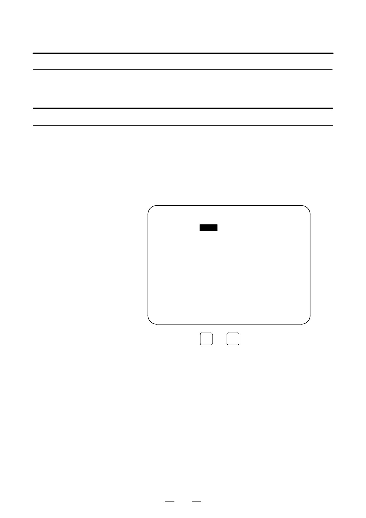
1
Manually move the reference tool to the reference position.
2
Reset the relative coordinates along the axes to 0 (see subsec.
III-11.1.2).
3
Move the tool for which offset values are to be set to the reference
position.
4
Select the tool compensation screen. Move the cursor to the offset
value to be set using cursor keys.
OFFSET/GEOMETRY
O0001 N00000
NO.
X
Z.
R
T
G 001
0.000
1.000
0.000
0
G 002
1.486
-49.561
0.000
0
G 003
1.486
-49.561
0.000
0
G 004
1.486
0.000
0.000
0
G 005
1.486
-49.561
0.000
0
G 006
1.486
-49.561
0.000
0
G 007
1.486
-49.561
0.000
0
G 008
1.486
-49.561
0.000
0
ACTUAL POSITION (RELATIVE)
U
0.000
W
0.000
V
0.000
H
0.000
>X_
HND **** *** ***
16:05:59
[NO,SRH][ MEASUR ][ INP.C. ][ +INPUT ][ INPUT ]
5
Press address key
X
(or
Z
) and the soft key [INP.C.].
Explanations
D Geometry offset and
When the above operations are performed on the tool geometry
wear offset
compensation screen, tool geometry compensation values are input and
tool wear compensation values do not change.
When the above operations are performed on the tool wear compensation
screen, tool wear compensation values are input and tool geometry
compensation values do not change.
753
11. SETTING AND DISPLAYING DATA
OPERATION
B-63524EN/01
11.4.5
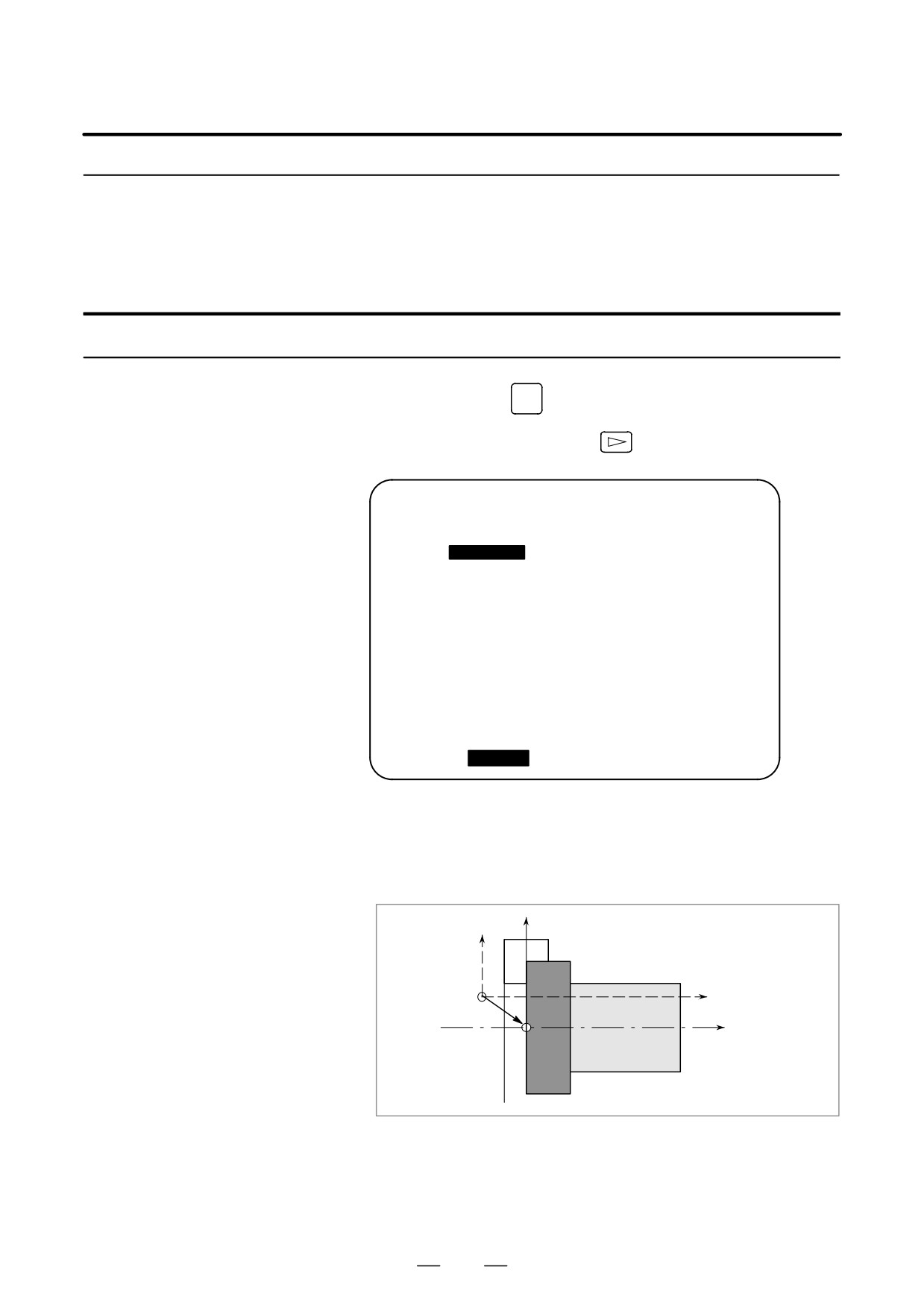
The set coordinate system can be shifted when the coordinate system
which has been set by a G50 command (or G92 command for G code
Setting the Workpiece
system B or C) or automatic coordinate system setting is different from
Coordinate System
the workpiece coordinate system assumed at programming.
Shifting Amount
Procedure for setting the workpiece coordinate system shifting amount
OFFSET
1
Press function key
SETTING
2
Press the continuous menu key
several times until the screen
with soft key [WK.SHFT] is displayed.
WORK SHIFT
O0001 N00000
(SHIFT VALUE)
(MEASUREMENT)
X
0.000
X
0.000
Z
0.000
Z
0.000
ACTUAL POSITION (RELATIVE)
U
0.000
W
0.000
> MZ100._
MDI **** *** ***
16:05:59
[
][ WK.SHFT
][
][ +INPUT ][ INPUT ]
3
Press soft key [WK.SHFT].
4
Move the cursor using cursor keys to the axis along which the
coordinate system is to be shifted.
5
Enter the shift value and press soft key [INPUT].
X
X’
ÇÇ
ÇÇ
O’
Z’
ÇÇ
Shift
Z
O
754
B-63524EN/01
OPERATION
11. SETTING AND DISPLAYING DATA
Explanations
D When shift values
Shift values become valid immediately after they are set.
become valid
D Shift values and
Setting a command (G50 or G92) for setting a coordinate system disables
coordinate system
the set shift values.
setting command
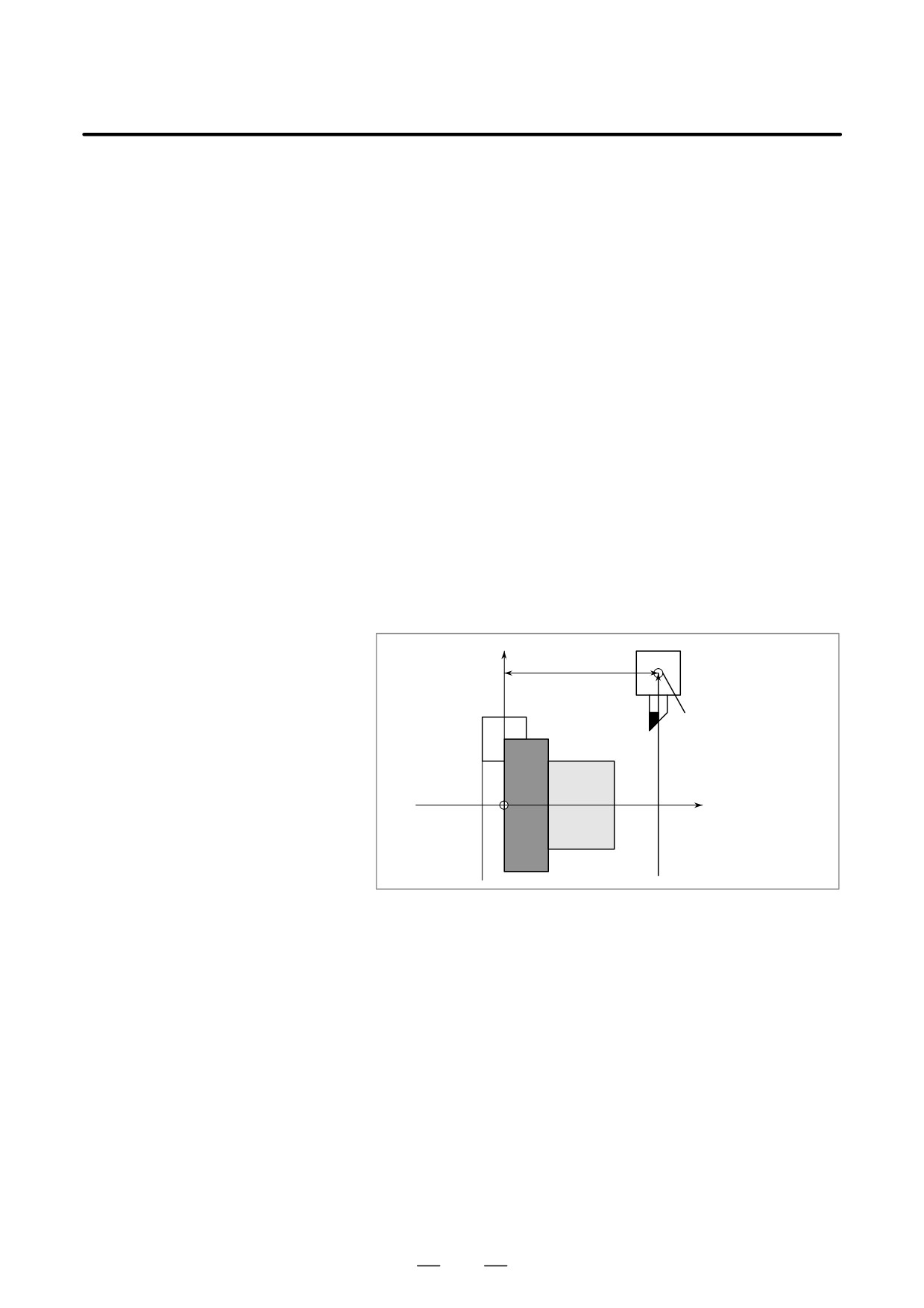
Example When G50 X100.0 Z80.0; is specified, the coordinate system
is set so that the current tool reference position is X+100.0,
Z+80.0 regardless of the shift values.
D Shift values and
If the automatic coordinate system setting is performed by manual
coordinate system
reference position return after shift amount setting, the coordinate system
setting
is shifted instantly.
D Diameter or radius value
Whether the shift amount on the X-axis is diameter or radius value
depends on that specified in program.
Examples
When the actual position of the reference point is X+121.0 (diameter),
Z+69.0 with respect to the workpiece origin but it should be X+120.0,
Z+70.0, set the following shift values:
X+1.0, Z+*1.0
X
69.00
Start position
(Standard position)
ÇÇÇ
ÇÇ
φ121.00
Z
755
11. SETTING AND DISPLAYING DATA
OPERATION
B-63524EN/01
11.4.6
Tool position offset values along the Y-axis can be set. Counter input of
offset values is also possible.
Y Axis Offset
Direct input of tool offset value and direct input function B for tool offset
measured are not available for the Y-axis.
Procedure for setting the tool offset value of the Y axis
OFFSET
1
Press function key
SETTING
2
Press the continuous menu key
several times until the screen
with soft key [OFST.2] is displayed.
3
Press soft key [OFST.2].
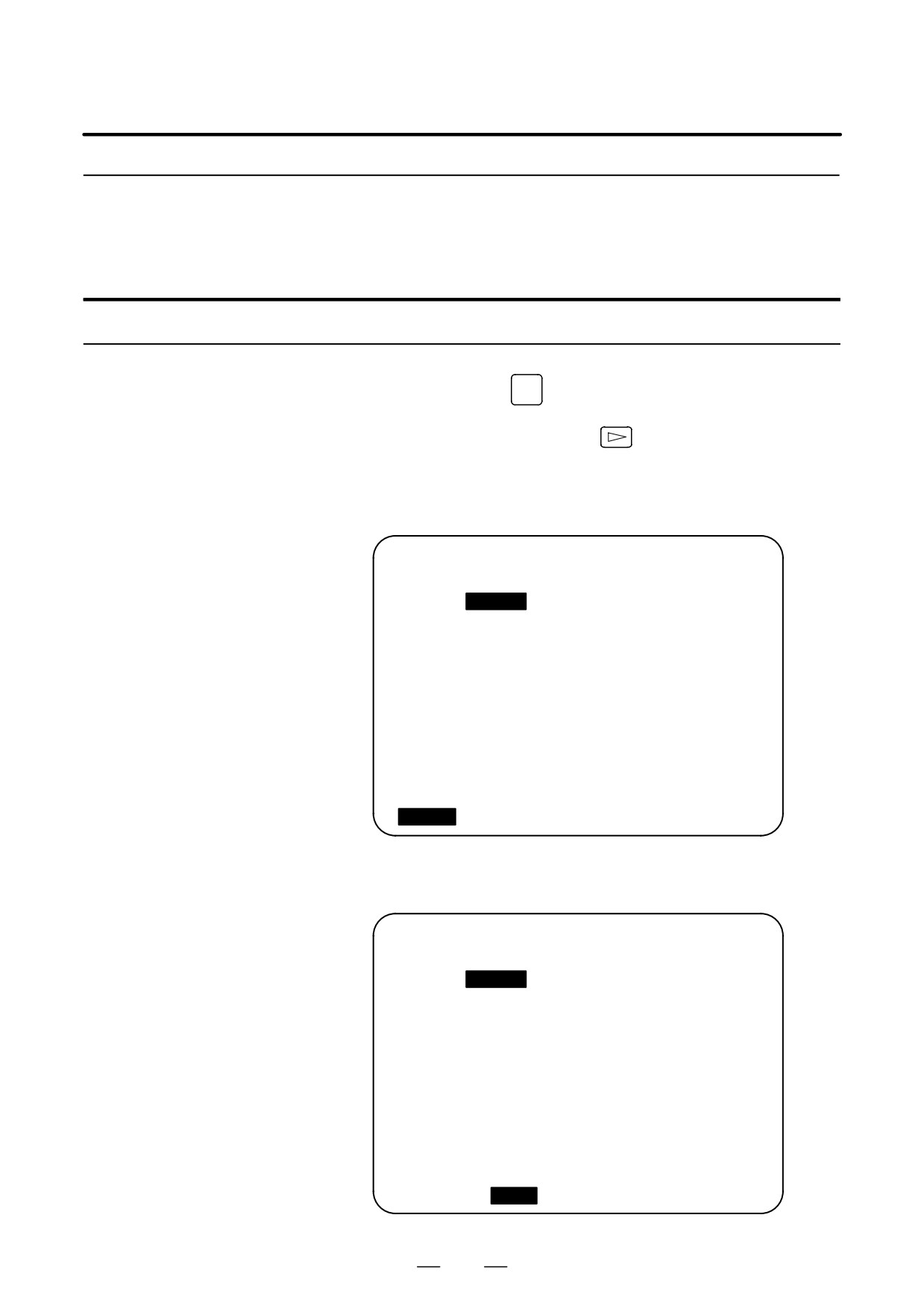
The Y axis offset screen is displayed.
OFFSET
O0001 N00000
NO.
Y
01
10.000
02
0.000
03
0.000
04
40.000
05
0.000
06
0.000
07
0.000
08
0.000
ACTUAL POSITION (RELATIVE)
U
100.000
W
100.000
>_
MDI **** *** ***
16:05:59
[
OFST.2
][ W.SHFT ][
][
][ (OPRT) ]
3-1 Press soft key
[GEOM] to display the tool geometry
compensation values along the Y-axis.
OFFSET/GEOMETRY
O0001 N00000
NO.
Y
G 01
10.000
G 02
0.000
G 03
0.000
G 04
40.000
G 05
0.000
G 06
0.000
G 07
0.000
G 08
0.000
ACTUAL POSITION (RELATIVE)
U
100.000
W
100.000
>_
MDI **** *** ***
16:05:59
[ WEAR
][
GEOM
][
][
][ (OPRT) ]
756
B-63524EN/01
OPERATION
11. SETTING AND DISPLAYING DATA
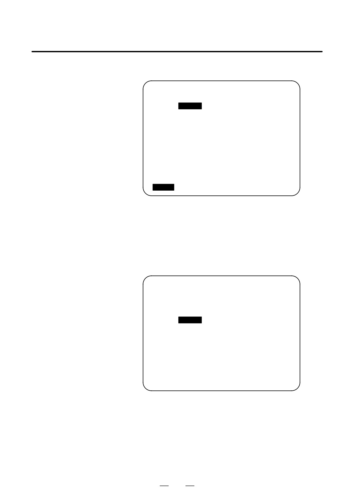
3-2 Press soft key [WEAR] to display the tool wear compensation
values along the Y-axis.
OFFSET/WEAR
O0001 N00000
NO.
Y
W 01
10.000
W 02
0.000
W 03
0.000
W 04
40.000
W 05
0.000
W 06
0.000
W 07
0.000
W 08
0.000
ACTUAL POSITION (RELATIVE)
U
100.000
W
100.000
>_
MDI **** *** ***
16:05:59
[
WEAR
][ GEOM
][
][
][ (OPRT) ]
4
Position the cursor at the offset number to be changed by using either
of the following methods:
D Move the cursor to the offset number to be changed using page
keys and cursor keys.
D Type the offset number and press soft key [NO.SRH].
5
Type the offset value.
6
Press soft key [WEAR]. The offset value is set and displayed.
OFFSET/WEAR
O0001 N00000
NO.
Y
W 01
10.000
W 02
0.000
W 03
0.000
W 04
40.000
W 05
0.000
W 06
0.000
W 07
0.000
W 08
0.000
ACTUAL POSITION (RELATIVE)
U
100.000
W
100.000
>_
MDI **** *** ***
16:05:59
[ NO.SRH ][ MEASUR ][ INP.C. ][ +INPUT ][ INPUT ]
757

11. SETTING AND DISPLAYING DATA
OPERATION
B-63524EN/01
Procedure for counter input of the offset value
To set relative coordinates along the Y-axis as offset values:
1
Move the reference tool to the reference point.
2
Reset relative coordinate Y to 0 (see subsec. III-11.1.2).
3
Move the tool for which offset values are to be set to the reference
point.
4
Move the cursor to the value for the offset number to be set, press
Y
, then press soft key [INP.C.].
Relative coordinate Y (or V) is now set as the offset value.
758