FANUC Series 0i-MC. OPERATOR’S MANUAL - page 16
B-64124EN/01
OPERATION
2. OPERATIONAL DEVICES
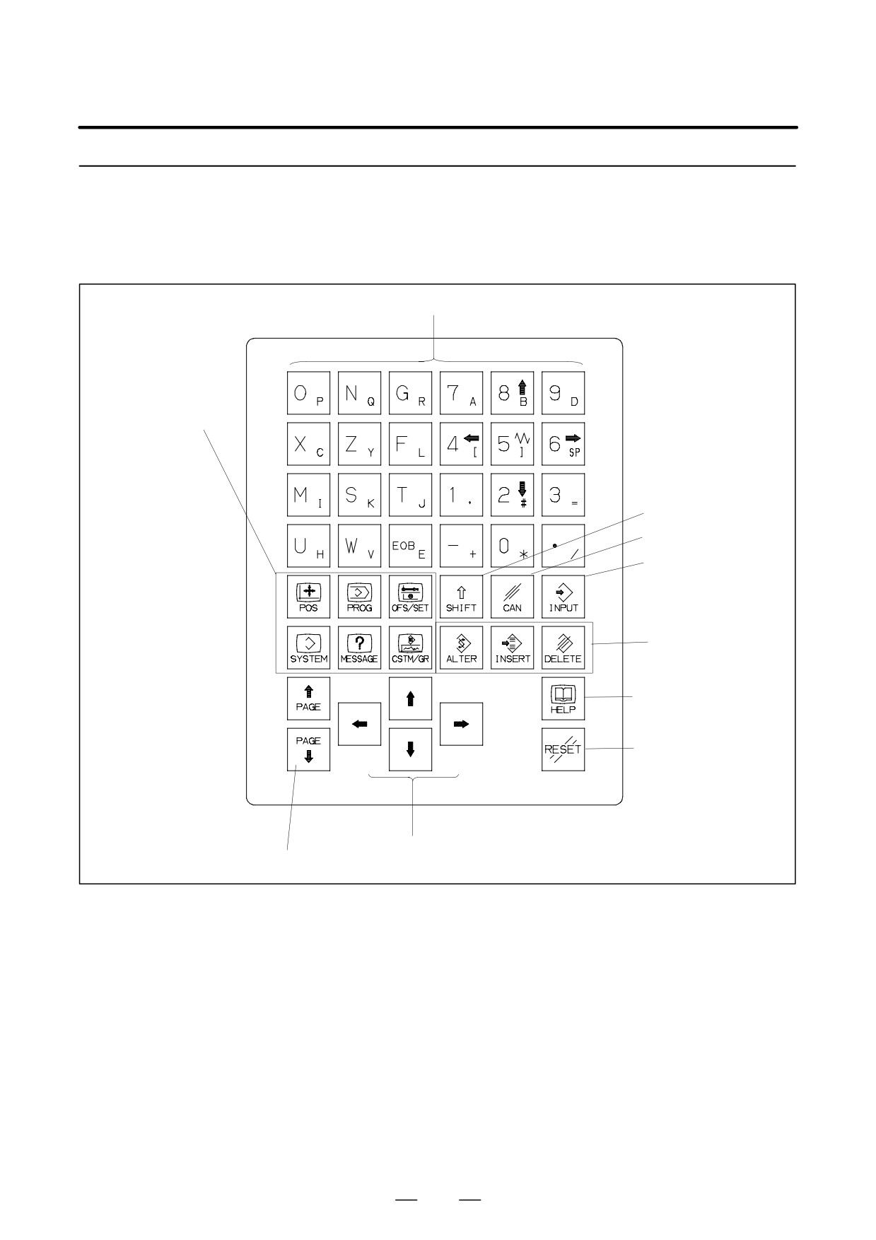
2.1.3
Key Location of MDI
(Horizontal Type
LCD/MDI Unit)
Address/numeric keys
Function keys
Shift key
Cancel (CAN) key
Input key
Edit keys
Help key
Reset key
Cursor keys
Page change keys
433
2. OPERATIONAL DEVICES
OPERATION
B-64124EN/01
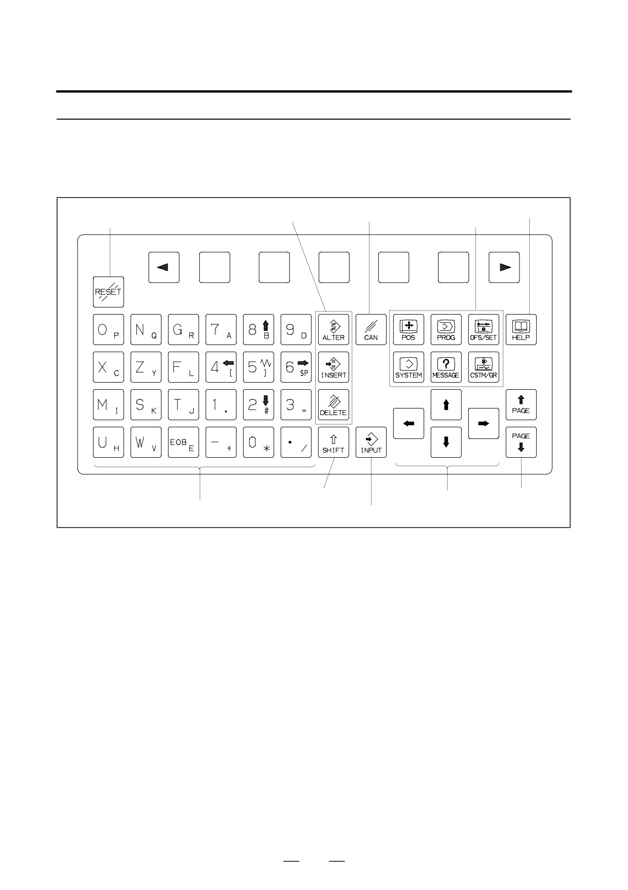
2.1.4
Key Location of MDI
(Vertical Type LCD/MDI
Unit)
Help key
Edit keys
Cancel (CAN) key
Reset key
Function keys
Shift key
Page change keys
Cursor keys
Address/numeric keys
Input key
434
B-64124EN/01
OPERATION
2. OPERATIONAL DEVICES
2.2
EXPLANATION OF
THE KEYBOARD
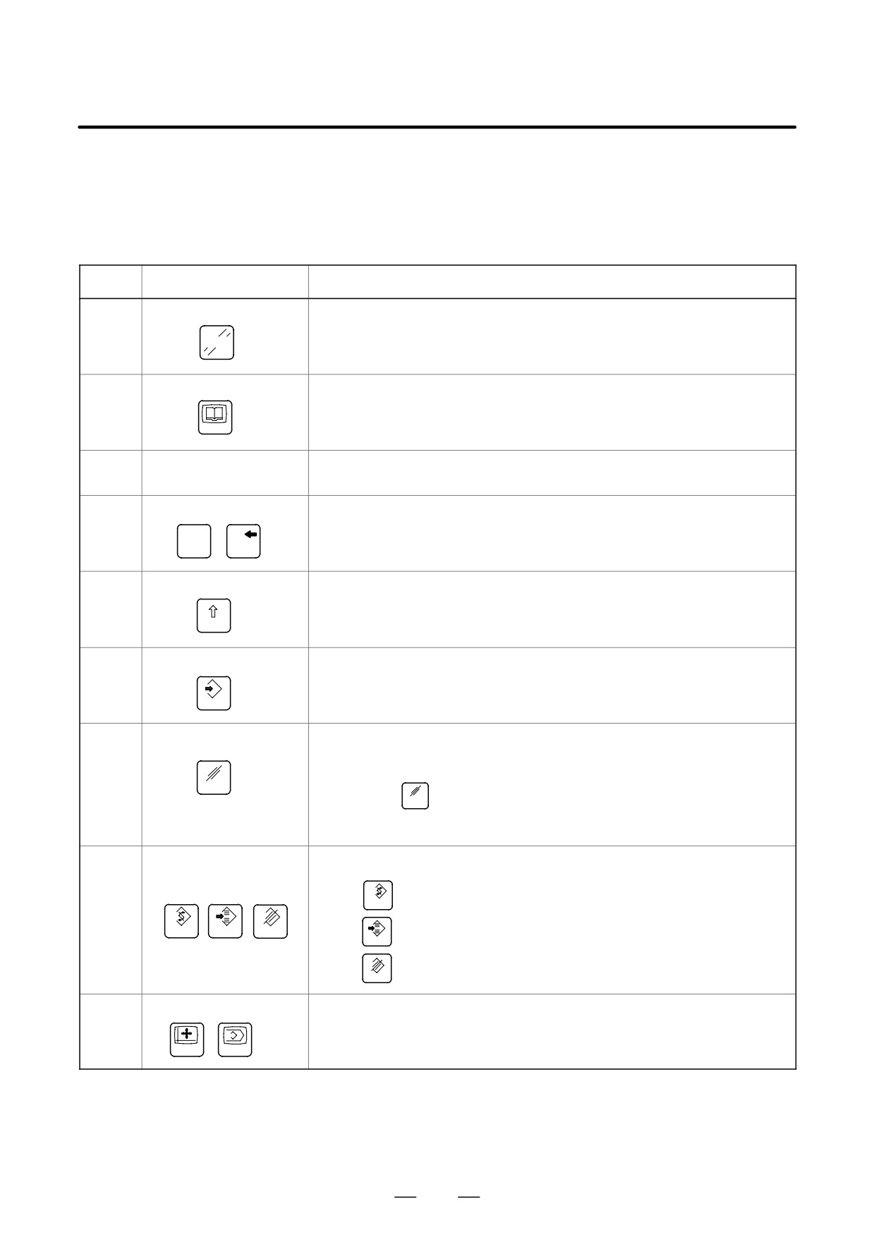
Table 2.2 Explanation of the MDI keyboard
Number
Name
Explanation
1
RESET key
Press this key to reset the CNC, to cancel an alarm, etc.
RESET
2
HELP key
Press this key to display how to operate the machine tool, such as MDI key operation,
or the details of an alarm which occurred in the CNC (Help function).
HELP
3
Soft keys
The soft keys have various functions, according to the Applications. The soft key
functions are displayed at the bottom of the screen.
4
Address and numeric keys
Press these keys to input alphabetic, numeric, and other characters.
N
4
…
Q
[
5
SHIFT key
Some keys have two characters on their keytop. Pressing the <SHIFT> key
switches the characters. Special character ƞ is displayed on the screen when a
character indicated at the bottom right corner on the keytop can be entered.
SHIFT
6
INPUT key
When an address or a numerical key is pressed, the data is input to the buffer, and
it is displayed on the screen. To copy the data in the key input buffer to the offset reg-
ister, etc., press the <INPUT> key. This key is equivalent to the [INPUT] key of the
INPUT
soft keys, and either can be pressed to produce the same result.
7
Cancel key
Press this key to delete the last character or symbol input to the key input buffer.
When the key input buffer displays
>N001X100Z_
CAN
and the cancel
CAN
key is pressed, Z is canceled and
>N001X100_
is displayed.
8
Program edit keys
Press these keys when editing the program.
: Alteration
ALTER
ALTER
INSERT
DELETE
: Insertion
INSERT
: Deletion
DELETE
9
Function keys
Press theses keys to switch display screens for each function.
See sec. III-2.3 for details of the function keys.
…
POS
PROG
435
2. OPERATIONAL DEVICES
OPERATION
B-64124EN/01
Table 2.2 Explanation of the MDI keyboard
Number
Name
Explanation
10
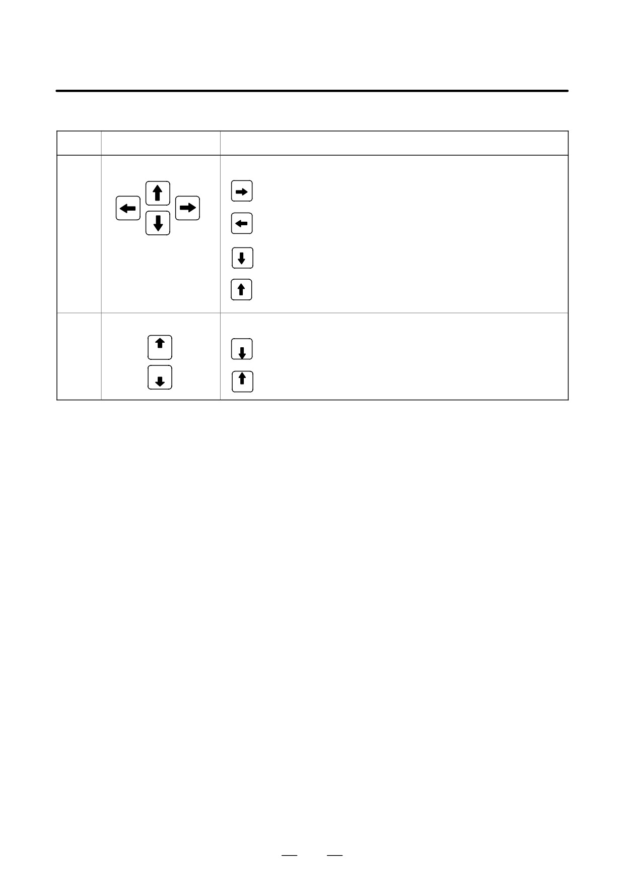
Cursor move keys
There are four different cursor move keys.
: This key is used to move the cursor to the right or in the forward
direction. The cursor is moved in short units in the forward direction.
: This key is used to move the cursor to the left or in the reverse
direction. The cursor is moved in short units in the reverse direction.
: This key is used to move the cursor in a downward or forward
direction. The cursor is moved in large units in the forward direction.
: This key is used to move the cursor in an upward or reverse direction.
The cursor is moved in large units in the reverse direction.
11
Page change keys
Two kinds of page change keys are described below.
PAGE
: This key is used to changeover the page on the screen in the forward
PAGE
direction.
PAGE
: This key is used to changeover the page on the screen in the reverse
PAGE
direction.
436
B-64124EN/01
OPERATION
2. OPERATIONAL DEVICES
2.3
The function keys are used to select the type of screen (function) to be
displayed. When a soft key
(section select soft key) is pressed
FUNCTION KEYS AND
immediately after a function key, the screen (section) corresponding to the
SOFT KEYS
selected function can be selected.
2.3.1
General Screen
Operations
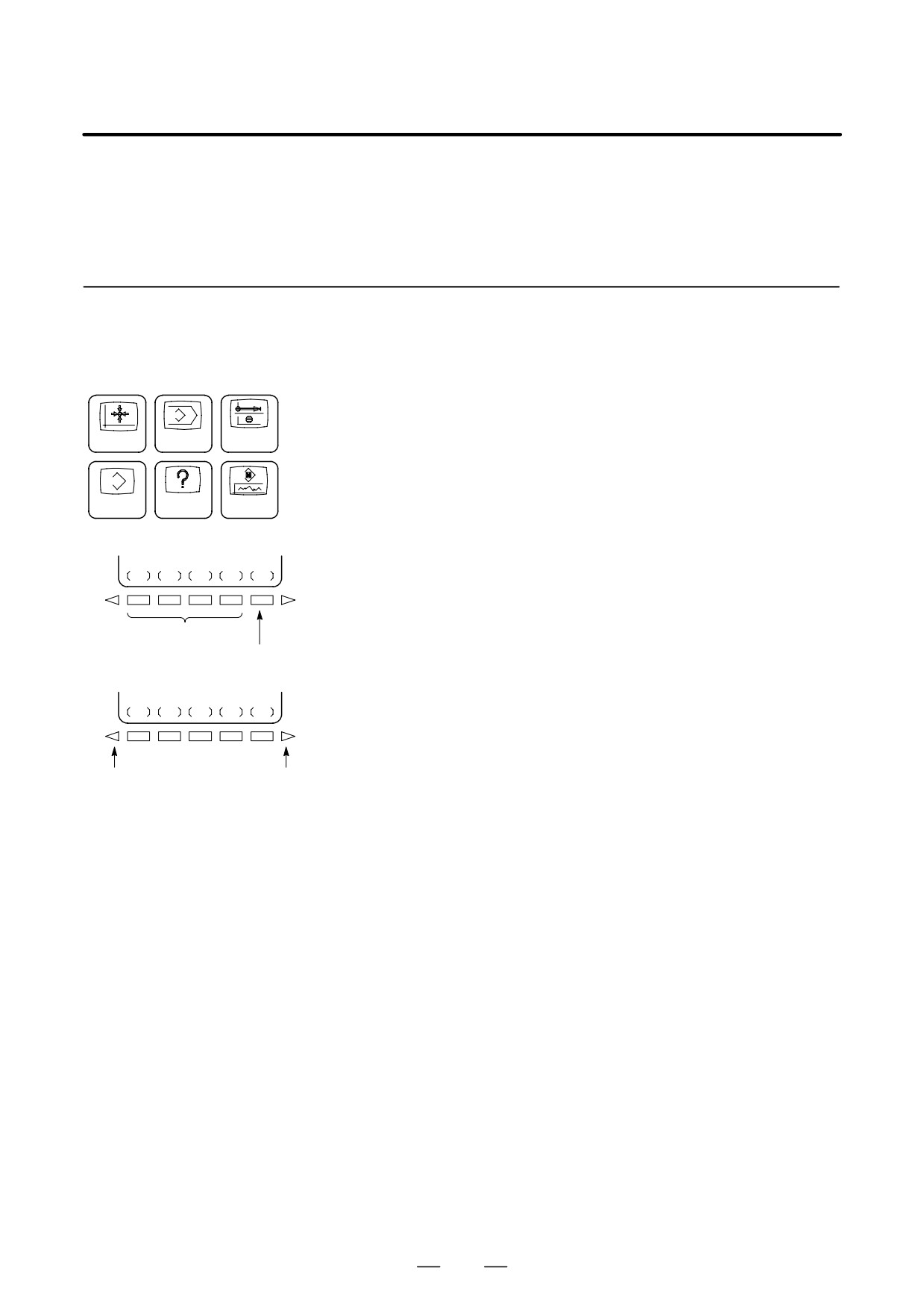
1
Press a function key on the MDI panel. The chapter selection soft
keys that belong to the selected function appear.
POS
PROG
OFS/SET
2
Press one of the chapter selection soft keys. The screen for the
selected chapter appears. If the soft key for a target chapter is not
displayed, press the continuous menu key (next-menu key).
SYSTEM
MESSAGE
CSTM/GR
In some cases, additional chapters can be selected within a chapter.
Function keys
3
When the target chapter screen is displayed, press the operation
selection key to display data to be manipulated.
(OPRT)
4
To redisplay the chapter selection soft keys, press the return menu
key.
Chapter selection
soft keys
Operation
selection
The general screen display procedure is explained above. However,
key
the actual display procedure varies from one screen to another. For
details, see the description of individual operations.
Return menu key
Continuous menu key
437
2. OPERATIONAL DEVICES
OPERATION
B-64124EN/01
2.3.2
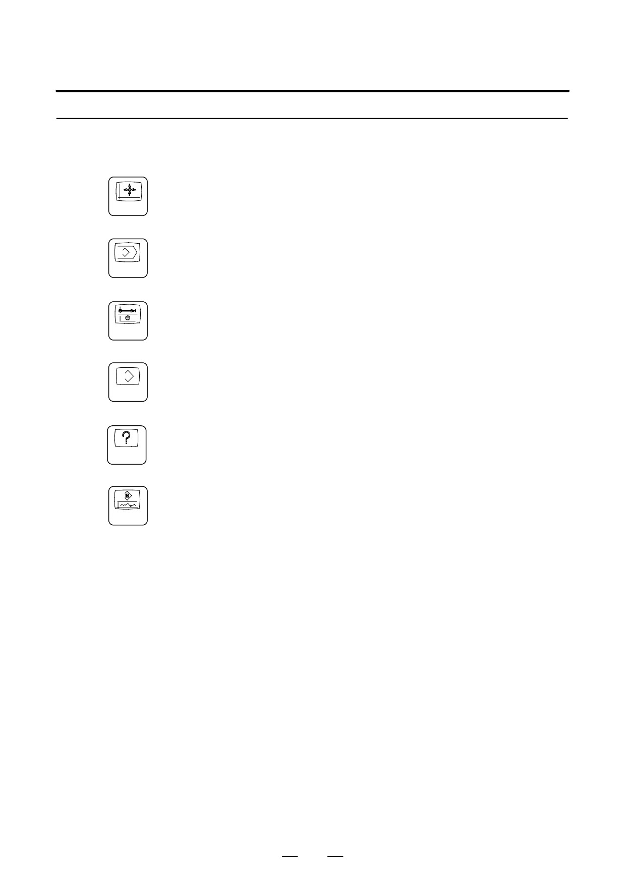
Function keys are provided to select the type of screen to be displayed.
The following function keys are provided on the MDI panel:
Function Keys
Press this key to display the position screen.
POS
Press this key to display the program screen.
PROG
Press this key to display the offset/setting screen.
OFS/SET
Press this key to display the system screen.
SYSTEM
Press this key to display the message screen.
MESSAGE
Press this key to display the custom screen (conversational macro
CSTM/GR
screen) and graphics screen.
438
B-64124EN/01
OPERATION
2. OPERATIONAL DEVICES
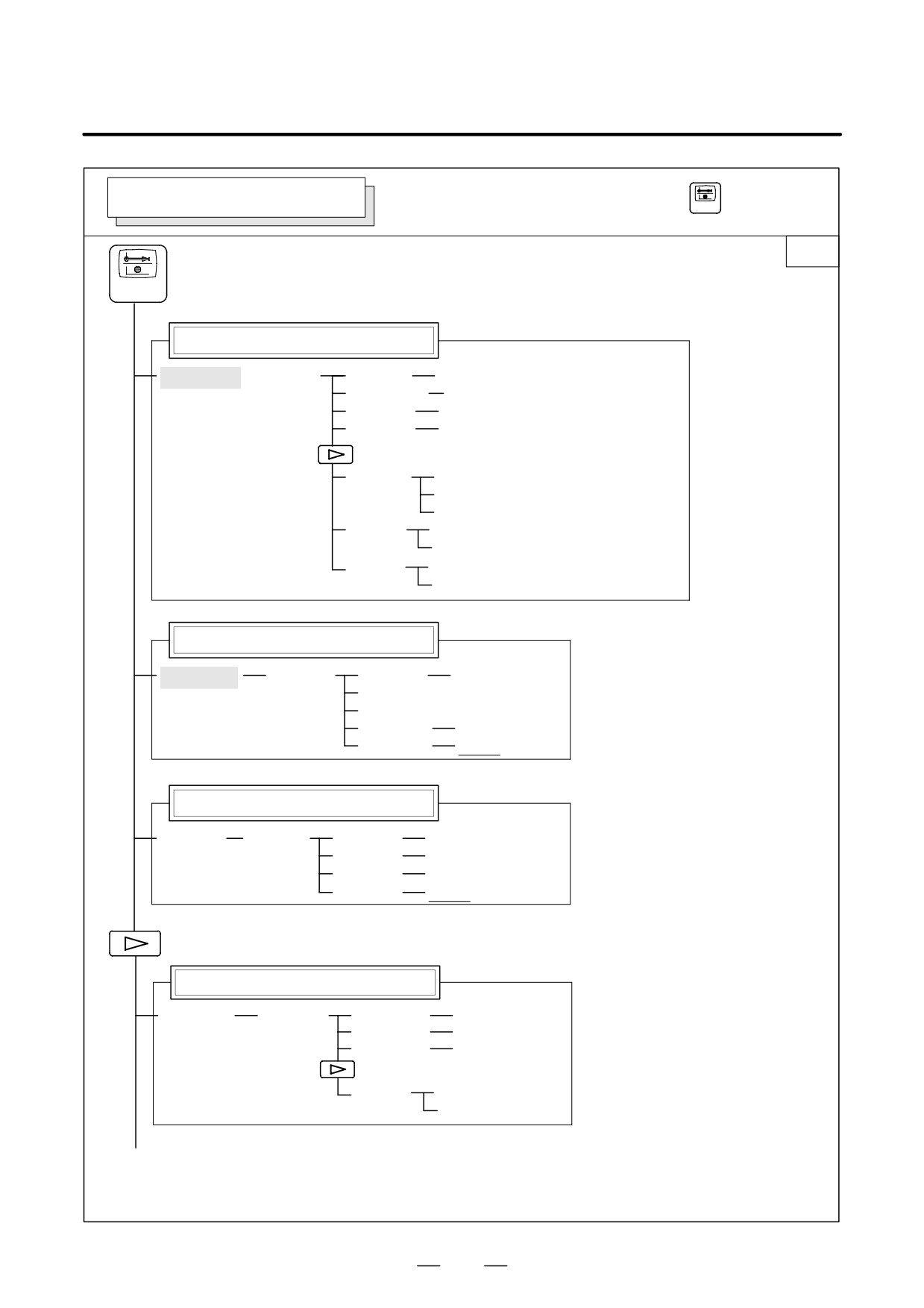
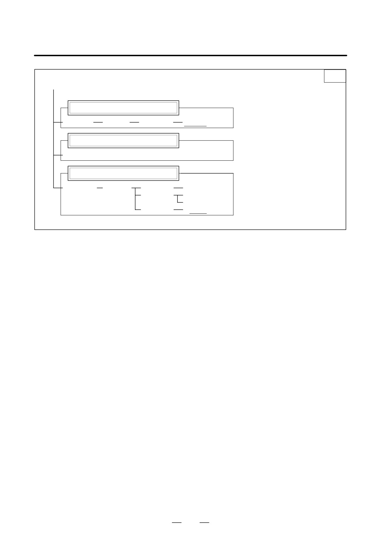
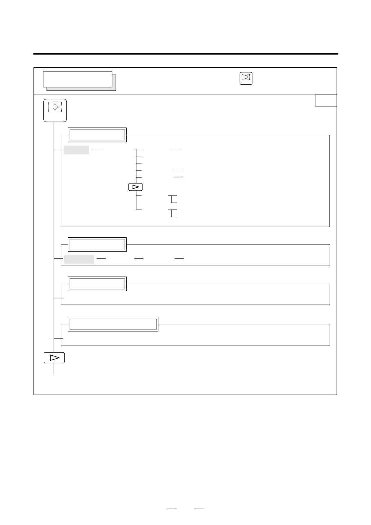
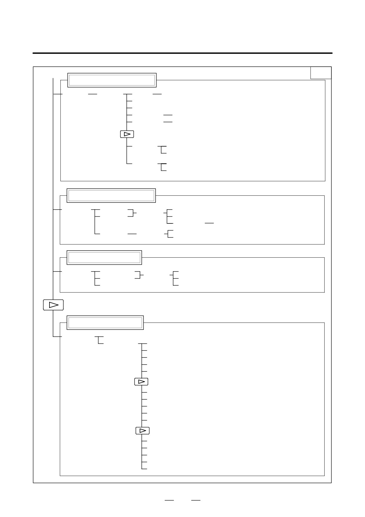
2.3.3
To display a more detailed screen, press a function key followed by a soft
key. Soft keys are also used for actual operations.
Soft Keys
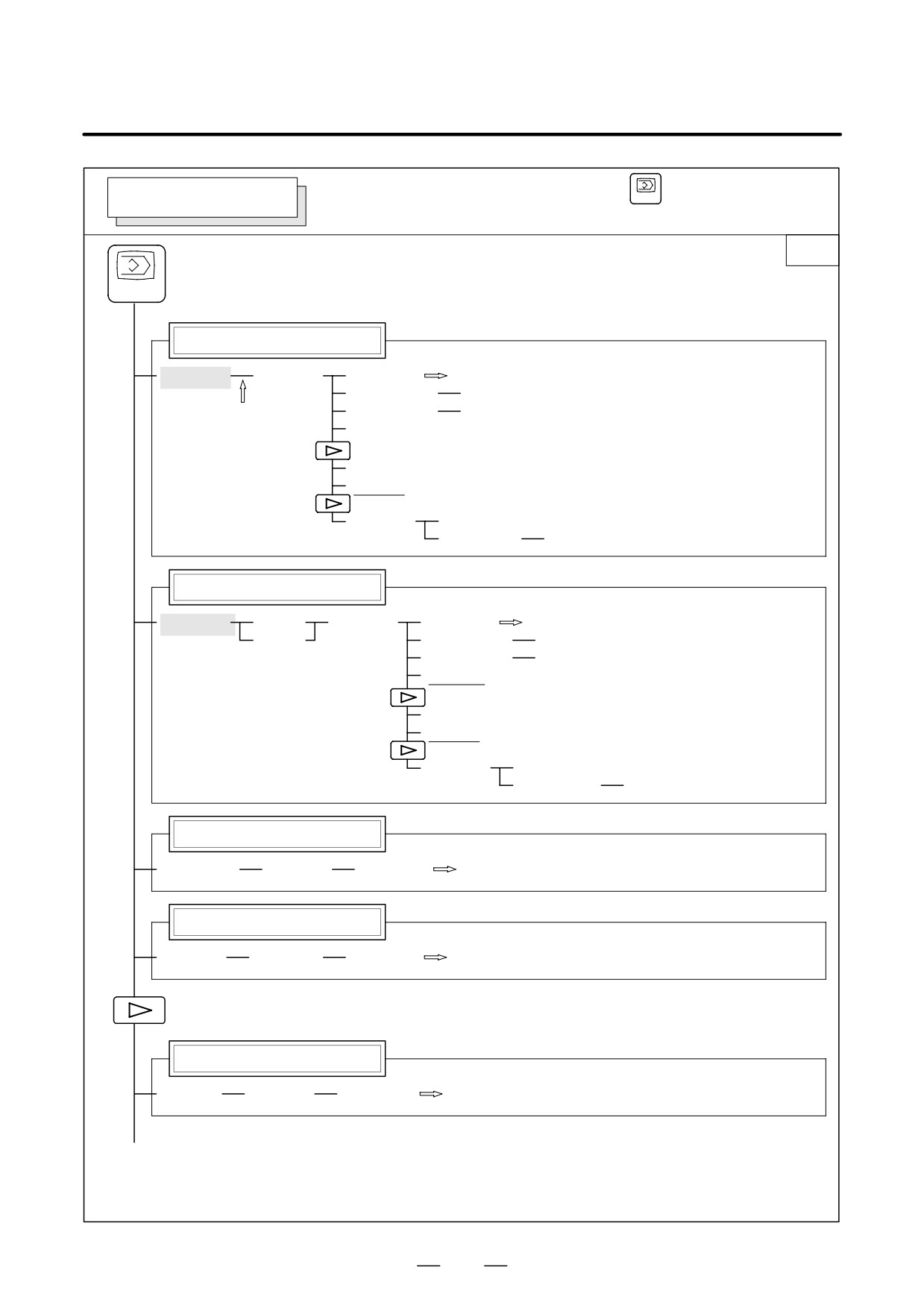
The following illustrates how soft key displays are changed by pressing
each function key.
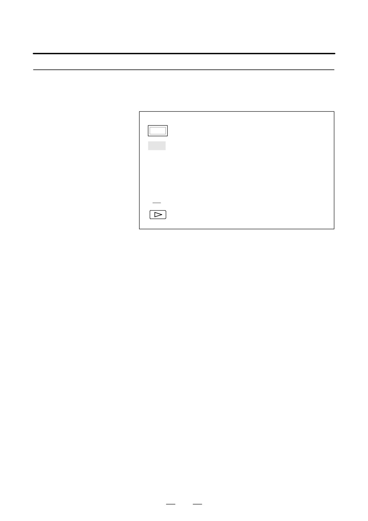
The symbols in the following figures mean as shown below :
: Indicates screens
: Indicates a screen that can be displayed by pressing a
function key(*1)
[
]
: Indicates a green-lettered soft key.(*2)
(
)
: Indicates input from the MDI panel.
[
]
: Indicates a black-lettered soft key.
: Indicates the continuous menu key (rightmost soft key).
*1 Press function keys to switch between screens that are used frequently.
*2 Some soft keys are not displayed depending on the option
configuration.
439
2. OPERATIONAL DEVICES
OPERATION
B-64124EN/01
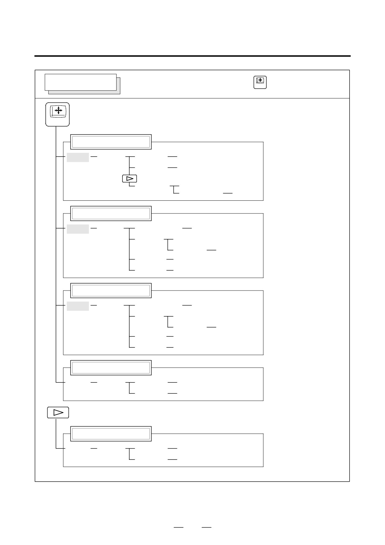
POSITION SCREEN
Soft key transition triggered by the function key
POS
POS
Absolute coordinate display
[ABS]
[(OPRT)]
[PTSPRE]
[EXEC]
[RUNPRE]
[EXEC]
[WRK-CD]
[ALLEXE]
(Axis name, 0)
[EXEC]
Relative coordinate display
[REL]
[(OPRT)]
(Axis or numeral)
[PRESET]
[ORIGIN]
[ALLEXE]
(Axis name)
[EXEC]
[PTSPRE]
[EXEC]
[RUNPRE]
[EXEC]
Current position display
[ALL]
[(OPRT)]
(Axis or numeral)
[PRESET]
[ORIGIN]
[ALLEXE]
(Axis name)
[EXEC]
[PTSPRE]
[EXEC]
[RUNPRE]
[EXEC]
Handle interruption
[HNDL]
[(OPRT)]
[PTSPRE]
[EXEC]
[RUNPRE]
[EXEC]
Monitor screen
[MONI]
[(OPRT)]
[PTSPRE]
[EXEC]
[RUNPRE]
[EXEC]
440
B-64124EN/01
OPERATION
2. OPERATIONAL DEVICES
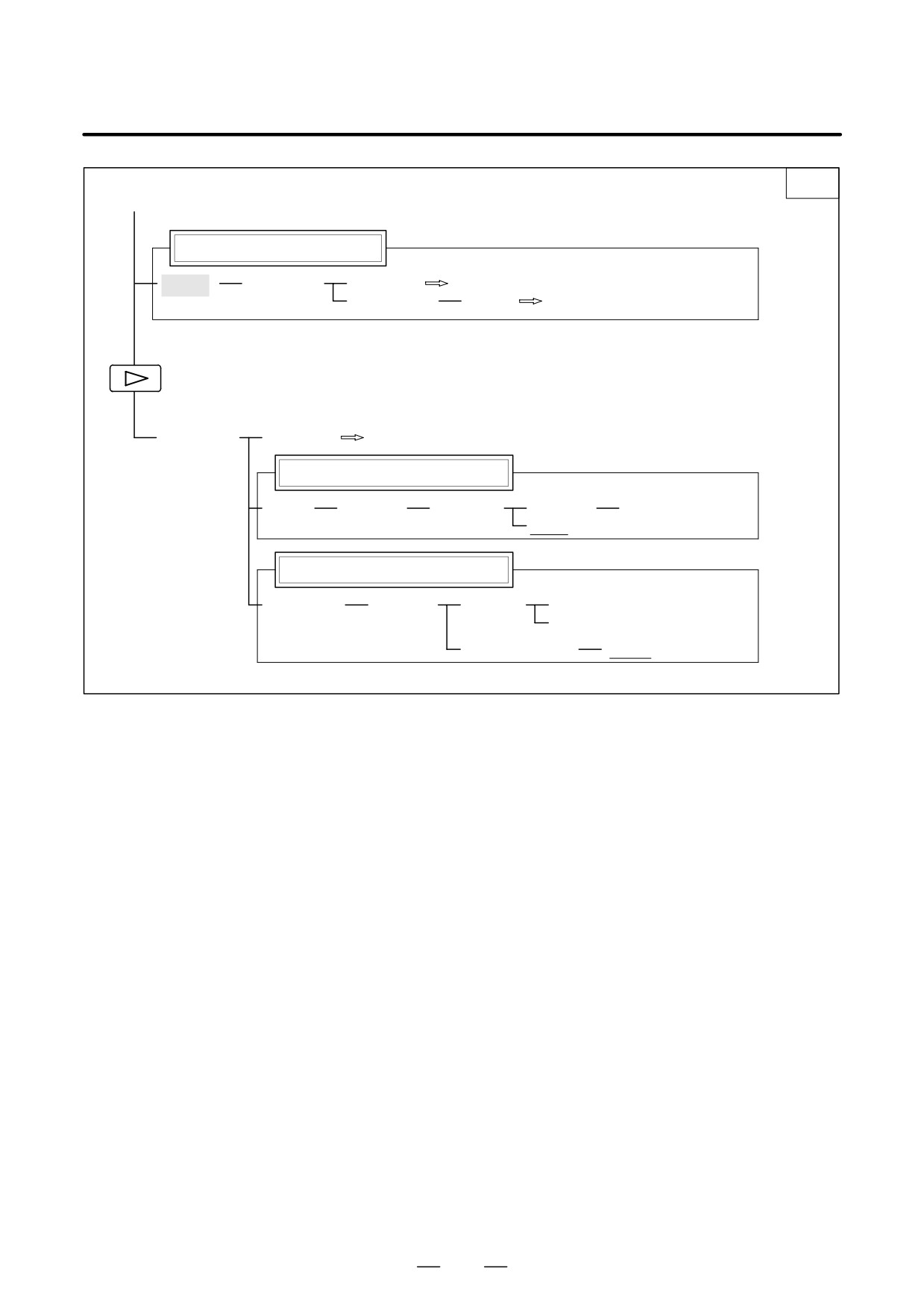
Soft key transition triggered by the function key
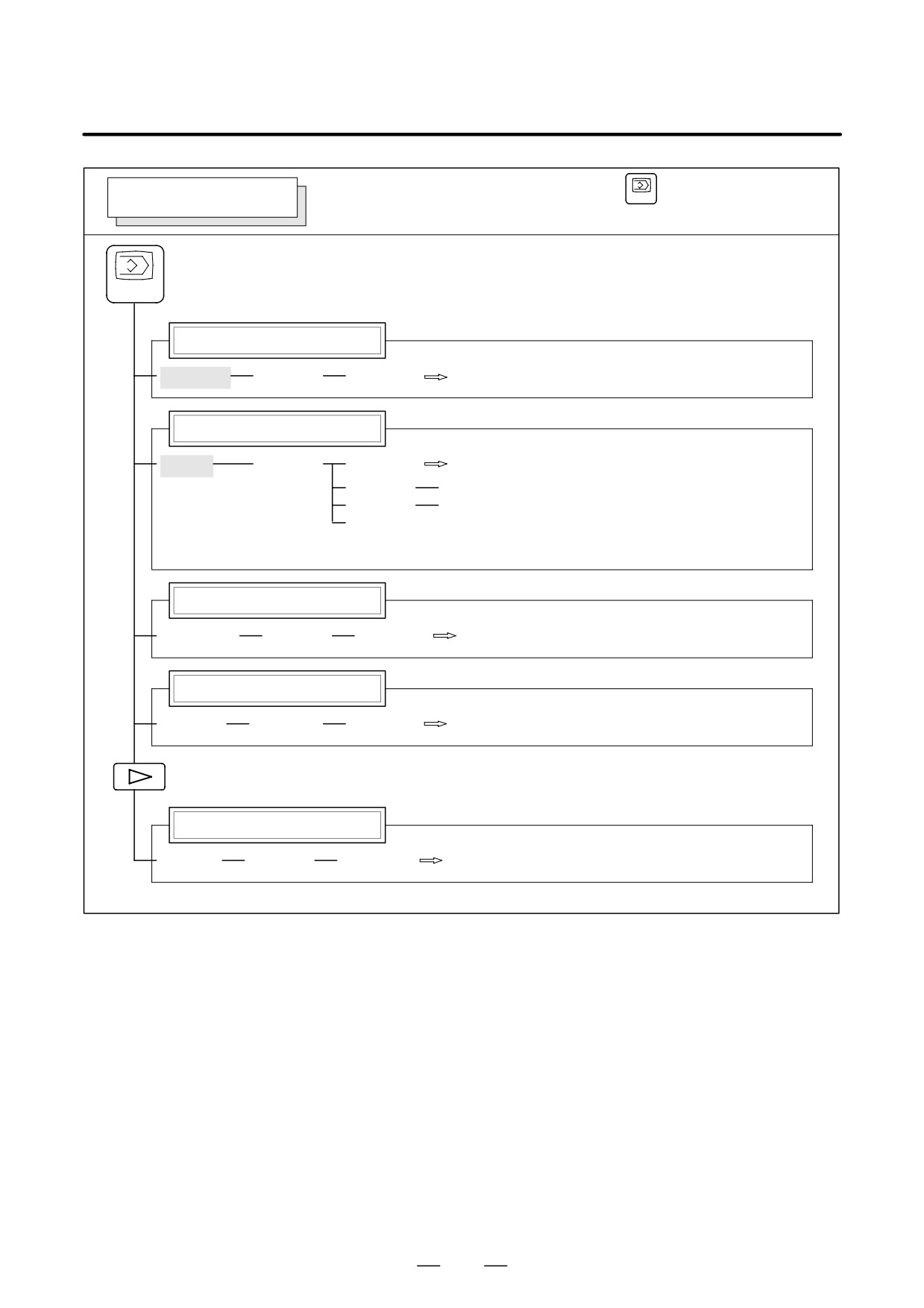
PROGRAM SCREEN
PROG
in the MEM mode
1/2
PROG
Program display screen
[PRGRM]
[(OPRT)]
[BG-EDT]
See “When the soft key [BG-EDT] is pressed”
(O number)
[O SRH]
(1)
(N number)
[N SRH]
[REWIND]
[P TYPE]
[Q TYPE]
[F SRH]
[CAN]
(N number)
[EXEC]
Program check display screen
[CHECK]
[ABS]
[(OPRT)]
[BG-EDT]
See “When the soft key [BG-EDT] is pressed”
[REL]
(O number)
[O SRH]
(N number)
[N SRH]
[REWIND]
[P TYPE]
[Q TYPE]
[F SRH]
[CAN]
(N number)
[EXEC]
Current block display screen
[CURRNT]
[(OPRT)]
[BG-EDT]
See “When the soft key [BG-EDT] is pressed”
Next block display screen
[NEXT]
[(OPRT)]
[BG-EDT]
See “When the soft key [BG-EDT] is pressed”
Program restart display screen
[RSTR]
[(OPRT)]
[BG-EDT]
See “When the soft key [BG-EDT] is pressed”
(2)(Continued on the next page)
441
2. OPERATIONAL DEVICES
OPERATION
B-64124EN/01
2/2
(2)
Program directory screen
[DIR]
[(OPRT)]
[BG-EDT]
See When the soft key [BG-EDT] is pressed"
(O number)
[O SRH]
Return to the program
[FL.SDL]
[PRGRM]
Return to (1) (Program display)
File directory display screen
[DIR]
[(OPRT)]
[SELECT]
(File No. )
[F SET]
[EXEC]
Schedule operation display screen
[SCHDUL]
[(OPRT)]
[CLEAR]
[CAN]
[EXEC]
(Schedule data)
[INPUT]
442
B-64124EN/01
OPERATION
2. OPERATIONAL DEVICES
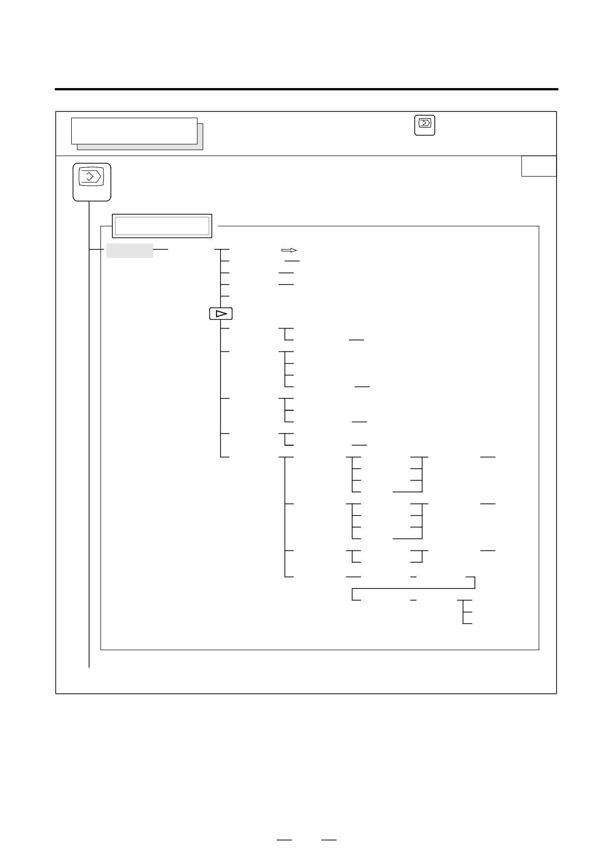
Soft key transition triggered by the function key
PROGRAM SCREEN
PROG
in the EDIT mode
1/2
PROG
Program display
[PRGRM]
[(OPRT)]
[BG-EDT]
See"When the soft key [BG-EDT] is pressed"
(O number)
[O SRH]
(Address)
[SRH↓]
(Address)
[SRH↑]
[REWIND]
[F SRH]
[CAN]
(N number)
[EXEC]
[READ]
[CHAIN]
(The cursor moves to the end of a program.)
[STOP]
[CAN]
(O number)
[EXEC]
[PUNCH]
[STOP]
[CAN]
(O number)
[EXEC]
[DELETE]
[CAN]
(N number)
[EXEC]
[EX-EDT]
[COPY]
[CRSR∼]
(O number)
[EXEC]
[∼CRSR]
[∼BTTM]
[ALL]
[MOVE]
[CRSR∼]
(O number)
[EXEC]
[∼CRSR]
[∼BTTM]
[ALL]
[MERGE]
[∼CRSR]
(O number)
[EXEC]
[∼BTTM]
[CHANGE]
(Address)
[BEFORE]
(Address)
[AFTER]
[SKIP]
[1-EXEC]
[EXEC]
(1)(Continued on the next page)
443
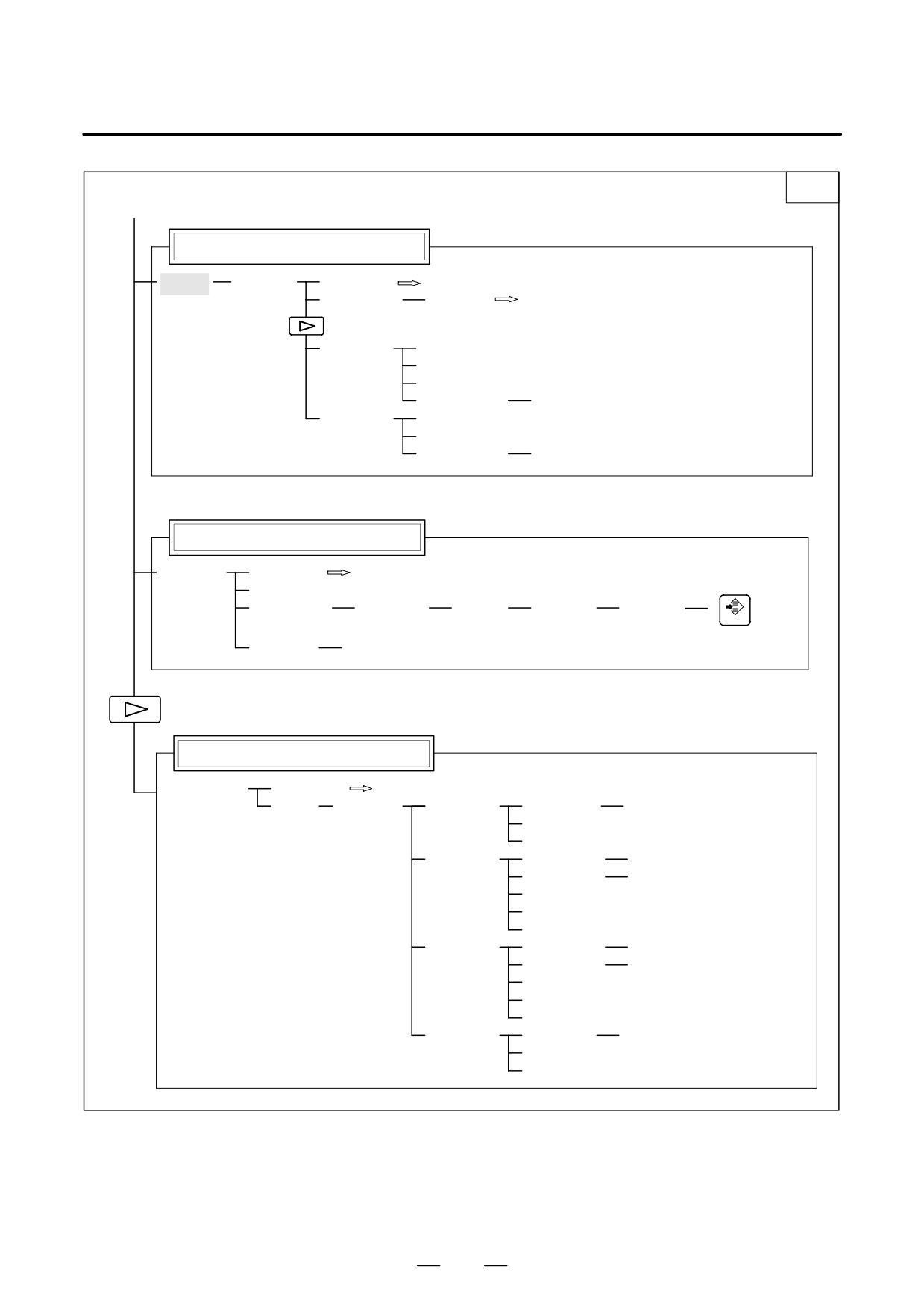
2. OPERATIONAL DEVICES
OPERATION
B-64124EN/01
2/2
(1)
Program directory display
[DIR]
[(OPRT)]
[BG-EDT]
See"When the soft key [BG-EDT] is pressed"
(O number)
[O SRH]
Return to the program
[READ]
[CHAIN]
[STOP]
[CAN]
(O number)
[EXEC]
[PUNCH]
[STOP]
[CAN]
(O number)
[EXEC]
Graphic Conversational Programming
[C.A.P.]
[PRGRM]
Return to the program
[G.MENU]
(G number)
[BLOCK]
(Data)
[(OPRT)]
[INPUT]
INSERT
When a G number is omitted, the standard screen appears.
[(OPRT)]
[INPUT]
Floppy directory display
[FLOPPY]
[PRGRM]
Return to the program
[DIR]
[(OPRT)]
[F SRH]
( number)
[F SET]
[CAN]
[EXEC]
[READ]
(number)
[F SET]
(O number)
[O SET]
[STOP]
[CAN]
[EXEC]
[PUNCH]
(number)
[F SET]
(O number)
[O SET]
[STOP]
[CAN]
[EXEC]
[DELETE]
(number)
[F SET]
[CAN]
[EXEC]
444
B-64124EN/01
OPERATION
2. OPERATIONAL DEVICES
Soft key transition triggered by the function key
PROGRAM SCREEN
PROG
in the MDI mode
PROG
Program display
[PRGRM]
[(OPRT)]
[BG-EDT]
See “When the soft key [BG-EDT] is pressed”
Program input screen
[MDI]
[(OPRT)]
[BG-EDT]
See “When the soft key [BG-EDT] is pressed”
(Address)
[SRH↓]
(Address)
[SRH↑]
[REWIND]
Current block display screen
[CURRNT]
[(OPRT)]
[BG-EDT]
See “When the soft key [BG-EDT] is pressed”
Next block display screen
[NEXT]
[(OPRT)]
[BG-EDT]
See “When the soft key [BG-EDT] is pressed”
Program restart display screen
[RSTR]
[(OPRT)]
[BG-EDT]
See “When the soft key [BG-EDT] is pressed”
445
2. OPERATIONAL DEVICES
OPERATION
B-64124EN/01
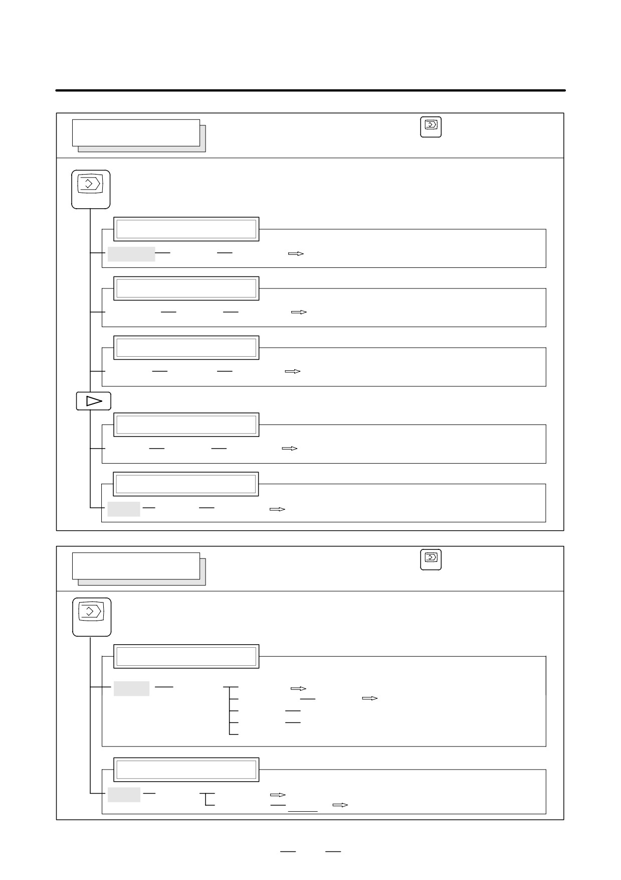
Soft key transition triggered by the function key
PROGRAM SCREEN
PROG
in the HNDL, JOG, or REF mode
PROG
Program display
[PRGRM]
[(OPRT)]
[BG-EDT]
See “When the soft key [BG-EDT] is pressed”
Current block display screen
[CURRNT]
[(OPRT)]
[BG-EDT]
See “When the soft key [BG-EDT] is pressed”
Next block display screen
[NEXT]
[(OPRT)]
[BG-EDT]
See “When the soft key [BG-EDT] is pressed”
Program restart display screen
[RSTR]
[(OPRT)]
[BG-EDT]
See “When the soft key [BG-EDT] is pressed”
Program directory display
[DIR]
[(OPRT)]
[BG-EDT]
See “When the soft key [BG-EDT] is pressed”
Soft key transition triggered by the function key
PROGRAM SCREEN
PROG
in the TJOG or THDL mode
PROG
Program display
[PRGRM]
[(OPRT)]
[BG-EDT]
See “When the soft key [BG-EDT] is pressed”
(O number)
[O SRH]
Return to the program
(Address)
[SRH↓]
(Address)
[SRH↑]
[REWIND]
Program directory display
[DIR]
[(OPRT)]
[BG-EDT]
See “When the soft key [BG-EDT] is pressed”
(O number)
[O SRH]
Return to the program
446
B-64124EN/01
OPERATION
2. OPERATIONAL DEVICES
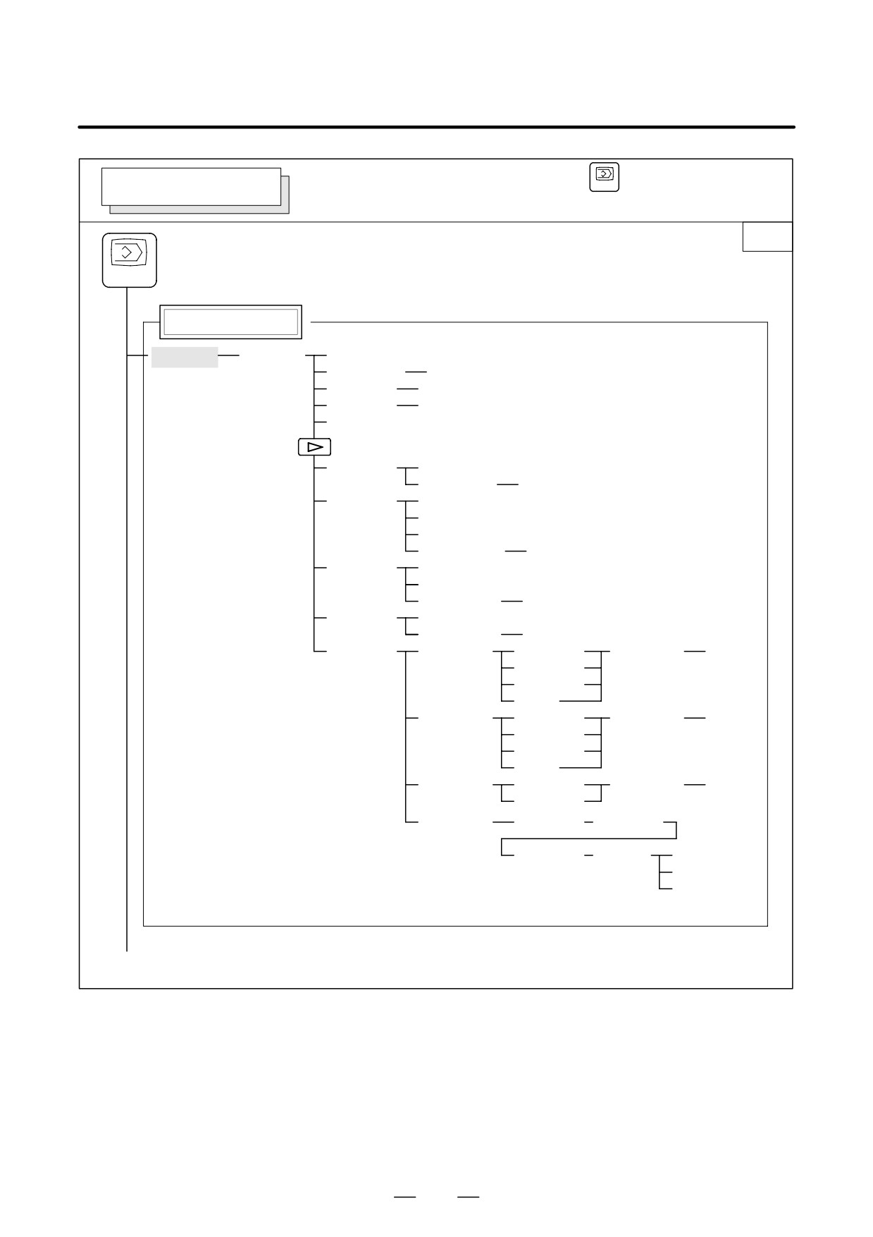
Soft key transition triggered by the function key
PROG
PROGRAM SCREEN
(When the soft key [BG-EDT] is pressed in all modes)
1/2
PROG
Program display
[PRGRM]
[(OPRT)]
[BG-END]
(O number)
[O SRH]
(Address)
[SRH↓]
(Address)
[SRH↑]
[REWIND]
[F SRH]
[CAN]
(N number)
[EXEC]
[READ]
[CHAIN]
(The cursor moves to the end of a program.)
[STOP]
[CAN]
(O number)
[EXEC]
[PUNCH]
[STOP]
[CAN]
(O number)
[EXEC]
[DELETE]
[CAN]
(N number)
[EXEC]
[EX-EDT]
[COPY]
[CRSR∼]
(O number)
[EXEC]
[∼CRSR]
[∼BTTM]
[ALL]
[MOVE]
[CRSR∼]
(O number)
[EXEC]
[∼CRSR]
[∼BTTM]
[ALL]
[MERGE]
[∼CRSR]
(O number)
[EXEC]
[∼BTTM]
[CHANGE]
(Address)
[BEFORE]
(Address)
[AFTER]
[SKIP]
[1-EXEC]
[EXEC]
(1)(Continued on the next page)
447
2. OPERATIONAL DEVICES
OPERATION
B-64124EN/01
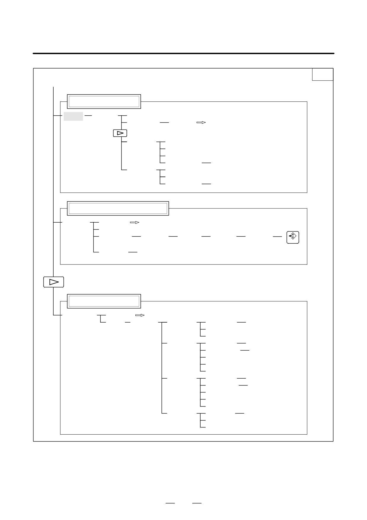
2/2
(1)
Program directory display
[DIR]
[(OPRT)]
[BG-EDT]
(O number)
[O SRH]
Return to the program
[READ]
[CHAIN]
[STOP]
[CAN]
(O number)
[EXEC]
[PUNCH]
[STOP]
[CAN]
(O number)
[EXEC]
Graphic Conversational Programming
[C.A.P.]
[PRGRM]
Return to the program
[G.MENU]
(G number)
[BLOCK]
(Data)
[(OPRT)]
[INPUT]
INSERT
When a G number is omitted, the standard screen appears.
[(OPRT)]
[INPUT]
Floppy directory display
[FLOPPY]
[PRGRM]
Return to the program
[DIR]
[(OPRT)]
[F SRH]
(number)
[F SET]
[CAN]
[EXEC]
[READ]
(number)
[F SET]
(O number)
[O SET]
[STOP]
[CAN]
[EXEC]
[PUNCH]
(number)
[F SET]
(O number)
[O SET]
[STOP]
[CAN]
[EXEC]
[DELETE]
(number)
[F SET]
[CAN]
[EXEC]
448
B-64124EN/01
OPERATION
2. OPERATIONAL DEVICES
OFFSET/SETTING SCREEN
Soft key transition triggered by the function key
OFS/SET
1/2
OFS/SET
Tool offset screen
[OFFSET]
[(OPRT)]
(Number)
[NO SRH]
(Axis name)
[INP.C.]
(Numeral)
[+INPUT]
(Numeral)
[INPUT]
[CLEAR]
[ALL]
[WEAR]
[GEOM]
[READ]
[CAN]
[WEAR]
[PUNCH]
[CAN]
[EXEC]
Setting screen
[SETING]
[(OPRT)]
(Number)
[NO SRH]
[ON:1]
[OFF:0]
(Numeral)
[+INPUT]
(Numeral)
[INPUT]
Work coordinate system setting screen
[WORK]
[(OPRT)]
(Number)
[NO SRH]
(Numeral)
[+INPUT]
(Numeral)
[INPUT]
(Numeral)
[INPUT]
Macro variables display screen
[MACRO]
[(OPRT)]
(Number)
[NO SRH]
(Axis name)
[INP.C.]
(Numeral)
[INPUT]
[PUNCH]
[CAN]
[EXEC]
(1)
449
2. OPERATIONAL DEVICES
OPERATION
B-64124EN/01
2/2
(1)
Pattern data input screen
[MENU]
[(OPRT)]
(Number)
[SELECT]
Software operator’s panel screen
[OPR]
Tool life management setting screen
[TOOLLF]
[(OPRT)]
(Number)
[NO SRH]
[CLEAR]
[CAN]
[EXEC]
(Numeral)
[INPUT]
450
B-64124EN/01
OPERATION
2. OPERATIONAL DEVICES
SYSTEM SCREEN
Soft key transition triggered by the function key
SYSTEM
1/2
SYSTEM
Parameter screen
[PARAM]
[(OPRT)]
(Number)
[NO SRH]
[ON:1]
[OFF:0]
(Numeral)
[+INPUT]
(Numeral)
[INPUT]
[READ]
[CAN]
[EXEC]
[PUNCH]
[CAN]
Note) Search for the start of the file using
[EXEC]
the PRGRM screen for read/punch.
Diagnosis screen
[DGNOS]
[(OPRT)]
(Number)
[NO SRH]
PMC screen
[PMC]
System configuration screen
[SYSTEM]
(4)
(Continued on the next page)
451
2. OPERATIONAL DEVICES
OPERATION
B-64124EN/01
(4)
2/2
Pitch error compensation screen
[PITCH]
[(OPRT)]
(No.)
[NO SRH]
[ON:1]
[OFF:0]
(Numeral)
[+INPUT]
(Numeral)
[INPUT]
[READ]
[CAN]
[EXEC]
[PUNCH]
[CAN]
[EXEC]
Servo parameter screen
[SV.PRM]
[SV.SET]
[ON:1]
[(OPRT)]
[SV.TUN]
[OFF:0]
(Numeral)
[INPUT]
[TRACE]
[SV.TRC]
[(OPRT)]
[TRNSF]
Spindle parameter screen
[SP.PRM]
[SP.SET]
[ON:1]
[(OPRT)]
[SP.TUN]
[OFF:0]
[SP.MON]
[INPUT]
Waveform diagnosis screen
[W.DGNS]
[W.PRM]
[W.GRPH]
[STSRT]
[TIME→]
[←TIME]
[H-DOBL]
[H-HALF]
[STSRT]
[CH-1↑]
[CH-1↓]
[V-DOBL]
[V-HALF]
[STSRT]
[CH-2↑]
[CH-2↓]
[V-DOBL]
[V-HALF]
452
B-64124EN/01
OPERATION
2. OPERATIONAL DEVICES
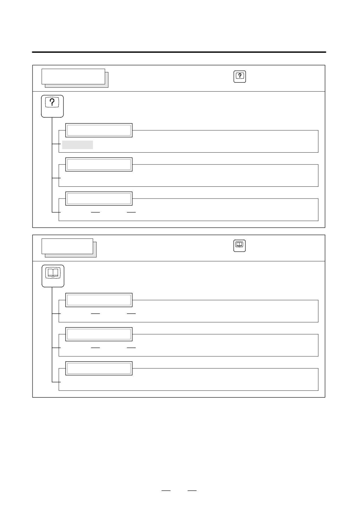
MESSAGE SCREEN
Soft key transition triggered by the function key
MESSAGE
MESSAGE
Alarm display screen
[ALARM]
Message display screen
[MSG]
Alarm history screen
[HISTRY]
[(OPRT)]
[CLEAR]
HELP SCREEN
Soft key transition triggered by the function key
HELP
HELP
Alarm detail screen
[ALAM]
[(OPRT)]
[SELECT]
Operation method screen
[OPR]
[(OPRT)]
[SELECT]
Parameter table screen
[PARA]
453
2. OPERATIONAL DEVICES
OPERATION
B-64124EN/01
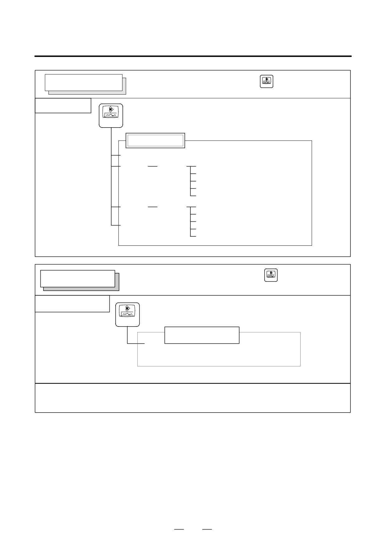
GRAPHIC SCREEN
Soft key transition triggered by the function key
CSTM/GR
Tool path graphics
CSTM/GR
Tool path graphics
[PARAM]
[EXEC]
[(OPRT)]
[AUTO]
[STSRT]
[STOP]
[REWIND]
[CLEAR]
[ZOOM]
[(OPRT)]
[EXEC]
[←]
[→]
[POS]
[↑]
[↓]
Soft key transition triggered by the function key
CSTM/GR
CUSTOM SCREEN
CUSTOM screen
CSTM/GR
CUSTOM screen
CUSTOM screen
The layout of the CUSTOM screen is customized by the machine tool builder. For details of the screen, refer to the
manual issued by the machine tool builder.
To switch from the CUSTOM screen to another screen, press the desired function key.
454
B-64124EN/01
OPERATION
2. OPERATIONAL DEVICES
2.3.4
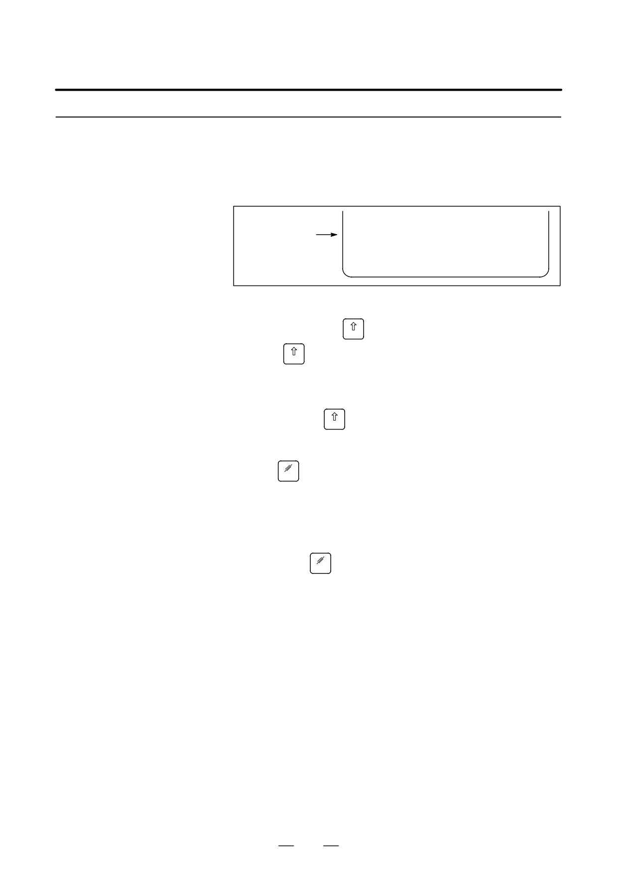
When an address and a numerical key are pressed, the character
corresponding to that key is input once into the key input buffer. The
Key Input and Input
contents of the key input buffer is displayed at the bottom of the screen.
Buffer
In order to indicate that it is key input data, a “>” symbol is displayed
immediately in front of it. A “_” is displayed at the end of the key input
data indicating the input position of the next character.
Key input buffer display
> N001X100Z_
EDIT
ALM 12:35:45
[
]
[
]
[
]
[
]
[
]
Fig. 2.3.4 Key input buffer display
To input the lower character of the keys that have two characters inscribed
on them, first press the
key and then the key in question.
SHIFT
When the
key is pressed, “_” indicating the next character input
SHIFT
position changes to “~”. Now lowercase characters can be entered (shift
state).
When a character is input in shift status the shift status is canceled.
Furthermore, if the
key is pressed in shift status, the shift status is
SHIFT
canceled.
It is possible to input up to 32 characters at a time in the key input buffer.
Press the
key to cancel a character or symbol input in the key input
CAN
buffer.
(Example)
When the key input buffer displays
>N001X100Z_
and the cancel
key is pressed, Z is canceled and
CAN
>N001X100_
is displayed.
455
2. OPERATIONAL DEVICES
OPERATION
B-64124EN/01
2.3.5
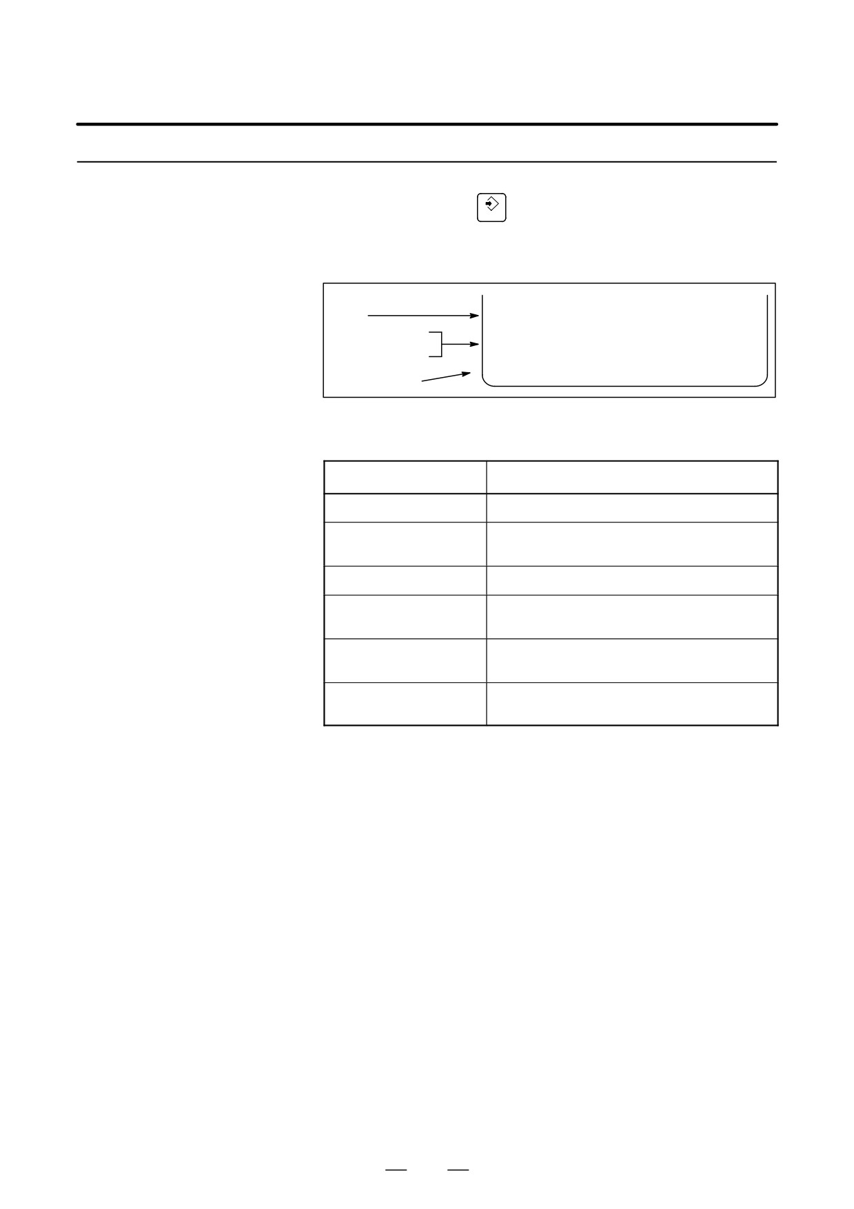
After a character or number has been input from the MDI panel, a data
Warning Messages
check is executed when
key or a soft key is pressed. In the case of
INPUT
incorrect input data or the wrong operation a flashing warning message
will be displayed on the status display line.
Display of key input
buffer
>_
Warning message
display
EDIT
WRONG MODE
Status display
[
]
[
]
[
]
[
]
[
]
Soft key display
Fig. 2.3.5 Warning message display
Table 2.3.5 Warning Messages
Warning message
Content
FORMAT ERROR
The format is incorrect.
WRITE PROTECT
Key input is invalid because of data protect key
or the parameter is not write enabled.
DATA IS OUT OF RANGE
The input value exceeds the permitted range.
TOO MANY DIGITS
The input value exceeds the permitted number
of digits.
WRONG MODE
Parameter input is not possible in any mode
other than MDI mode.
EDIT REJECTED
It is not possible to edit in the current CNC
status.
456
B-64124EN/01
OPERATION
2. OPERATIONAL DEVICES
2.4
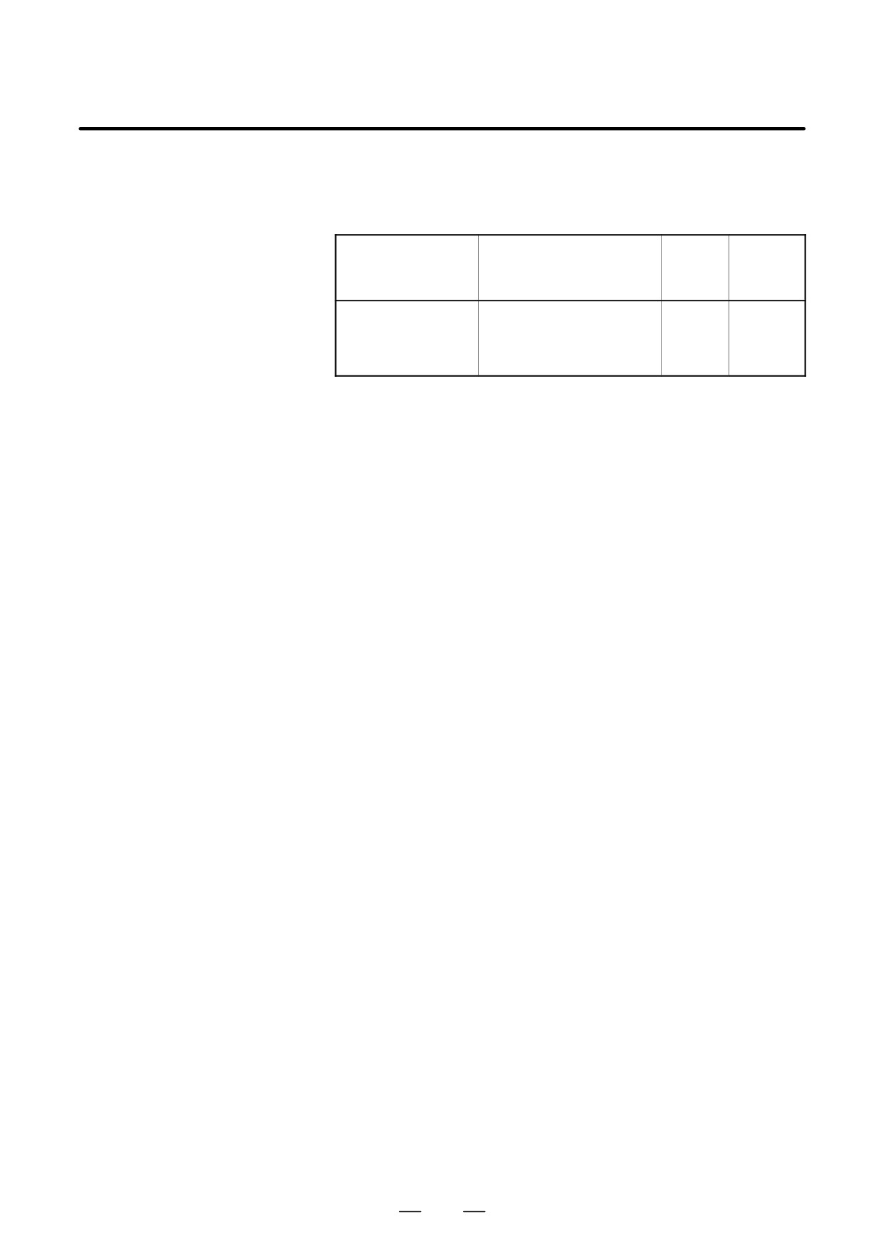
Handy File of external input/output device is available. For detail on
Handy File, refer to the corresponding manual listed below.
EXTERNAL I/O
Table 2.4 External I/O device
DEVICES
Device name
Usage
Max.
Reference
storage
manual
capacity
FANUC Handy File
Easy-to-use, multi function
3600m
B-61834E
input/output device. It is de-
signed for FA equipment and
uses floppy disks.
The following data can be input/output to or from external input/output
devices:
1. Programs
2. Offset data
3. Parameters
4. Custom macro common variables
5. Pitch error compensation data
For an explanation of data input/output and how to use a memory card to
input and output data, see Chapter III-8.
457
2. OPERATIONAL DEVICES
OPERATION
B-64124EN/01
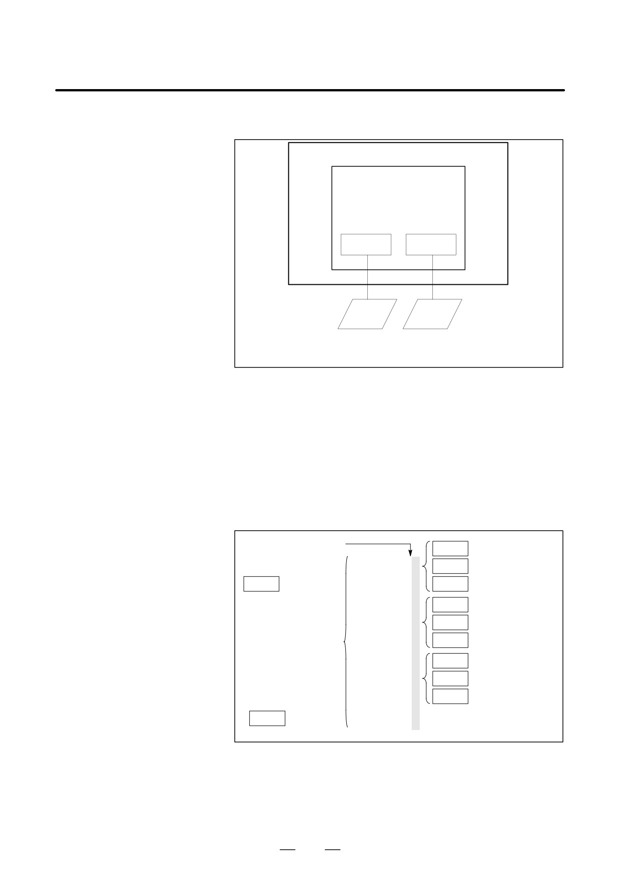
Parameter
Before an external input/output device can be used, parameters must be
set as follows.
CNC
MAIN CPU BOARD
Channel 1
Channel 2
JD36A
JD36B
RS-232-C
RS-232-C
Reader/
Reader/
puncher
puncher
I/O CHANNEL=0
I/O CHANNEL=2
or
I/O CHANNEL=1
CNC has two channels of reader/punch interfaces. The CNC has a
memory card interface as well. The input/output device to be used is
specified by setting the channel (interface) connected to that device in
setting parameter I/O CHANNEL.
The specified data, such as a baud rate and the number of stop bits, of an
input/output device connected to a specific channel must be set in
parameters for that channel in advance. (No data need be set for the
memory card interface.)
For channel 1, two combinations of parameters to specify the input/output
device data are provided.
The following shows the interrelation between the reader/punch interface
parameters for the channels.
Input/output channel
0101
Stop bit and other data
number (parameter
Number specified for
0020)
I/O CHANNEL=0
0102
the input/output device
(channel 1)
0020
I/O CHANNEL
0103
Baud rate
Specify a channel for an
0111
Stop bit and other data
input/output device.
0112
Number specified for
I/O CHANNEL=1
the input/output device
(channel 1)
I/O CHANNEL
0113
Baud rate
= 0 : Channel 1
= 1 : Channel 1
0121
Stop bit and other data
= 2 : Channel 2
= 4 : Memory card
I/O CHANNEL=2
Number specified for
0122
Interface
(channel 2)
the input/output device
0123
Baud rate
Parameter
Memory card = 4
Number
interface
458
B-64124EN/01
OPERATION
2. OPERATIONAL DEVICES
2.4.1
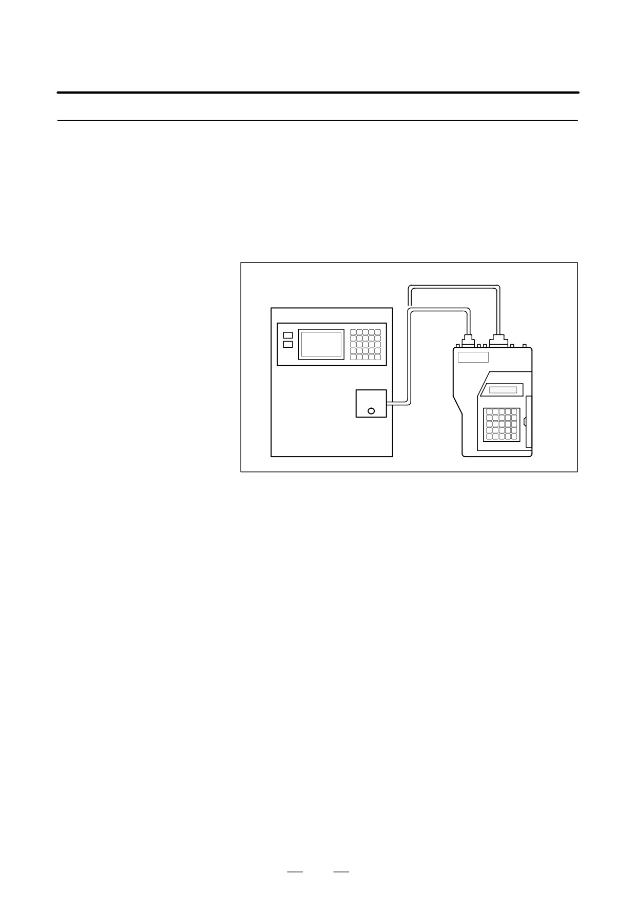
The Handy File is an easy-to-use, multi function floppy disk
input/output device designed for FA equipment. By operating the Handy
FANUC Handy File
File directly or remotely from a unit connected to the Handy File,
programs can be transferred and edited.
The Handy File uses 3.5-inch floppy disks, which do not have the
problems of paper tape (i.e., noisy during input/output, easily broken, and
bulky).
One or more programs (up to 1.44M bytes, which is equivalent to the
memory capacity of 3600-m paper tape) can be stored on one floppy disk.
RS-422
Interface
RS-232-C
Interface
FANUC
Handy File
RS-232-C or
RS-422 Interface
(Punch panel, etc.)
459

2. OPERATIONAL DEVICES
OPERATION
B-64124EN/01
2.5
POWER ON/OFF
2.5.1
Turning on the Power
Procedure of turning on the power
Procedure
1
Check that the appearance of the CNC machine tool is normal.
(For example, check that front door and rear door are closed.)
2
Turn on the power according to the manual issued by the machine
tool builder.
3
After the power is turned on, check that the position screen is
displayed. An alarm screen is displayed if an alarm occurs upon
power-on. If the screen shown in Section III-2.5.2 is displayed, a
system failure may have occurred.
Position display screen
ACTUAL POSITION(ABSOLUTE) O1000 N00010
X
123.456
Y
363.233
Z
0.000
PART COUNT
5
RUN TIME
0H15M
CYCLE TIME 0H 0M38S
ACT.F
3000 MM/M
S
0 T0000
MEM STRT MTN ***
09:06:35
[ ABS
]
[ REL
]
[ ALL
]
[ HNDL
]
[ OPRT
]
4
Check that the fan motor is rotating.
WARNING
Until the positional or alarm screen is displayed at the power
on, do not touch them. Some keys are used for the
maintenance or special operation purpose. When they are
pressed, unexpected operation may be caused.
460
B-64124EN/01
OPERATION
2. OPERATIONAL DEVICES
2.5.2
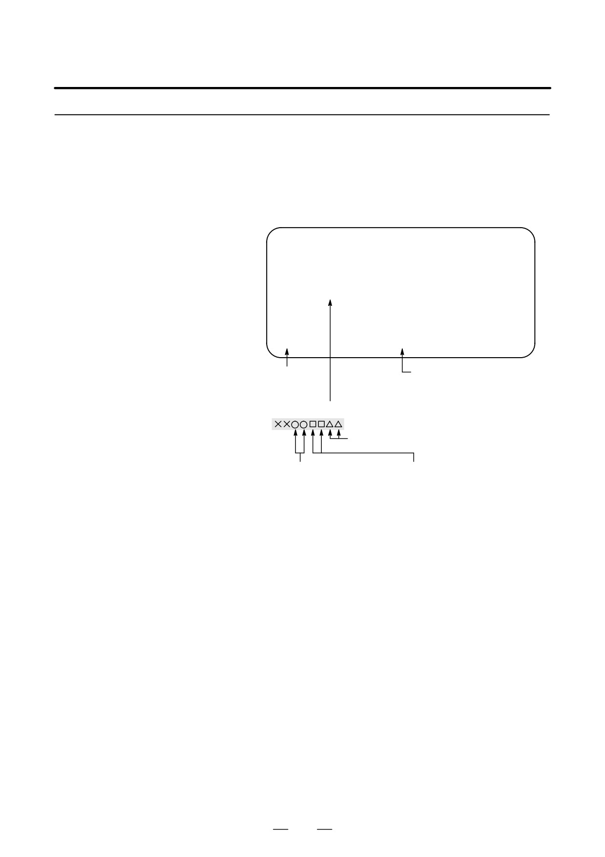
If a hardware failure or installation error occurs, the system displays one
of the following three types of screens then stops.
Screen Displayed at
Information such as the type of printed circuit board installed in each slot
Power-on
is indicated. This information and the LED states are useful for failure
recovery.
Slot status display
SLOT CONFIGURATION DISPLAY
0 : 003E4000
0 :
1 : 30464202
1 :
2 : 00504303
2 :
3 :
3 :
4 :
4 :
5 :
5 :
Physical slot number
Physical slot number
(primary)
(secondary)
Information such as the module ID of an installed printed circuit board
Internally-assigned slot number
Types of printed circuit boards
Module function
For more information about the types of printed circuit boards and module
functions, refer to the MAINTENANCE MANUAL (B-64115EN).
461
2. OPERATIONAL DEVICES
OPERATION
B-64124EN/01
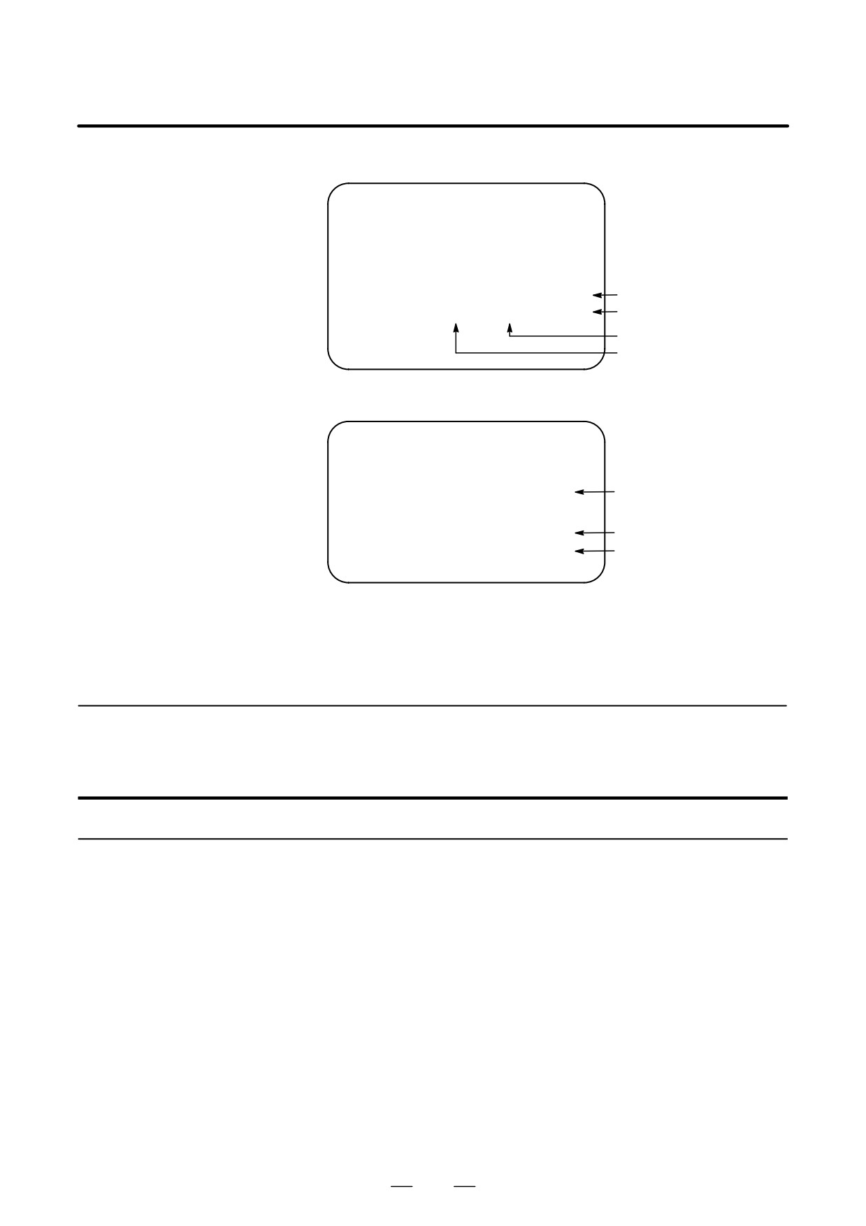
Screen indicating
module setting status
D4B1 - 01
SLOT 01 (3046) : END
END: Setting completed
SLOT 02 (3050) :
Blank: Setting not completed
Module ID
Slot number
Display of software
configuration
CNC control software
D4B1 - 01
Order-mademacro/macro
OMM : yyyy-yy
compiler
PMC : zzzz-zz
PMC
The software configuration can be displayed on the system configuration
screen also.
Refer to the MAINTENANCE MANUAL (B-64115EN) for the system
configuration screen.
2.5.3
Power Disconnection
Power Disconnection
Procedure
1
Check that the LED indicating the cycle start is off on the operator’s
panel.
2
Check that all movable parts of the CNC machine tool is stopping.
3
If an external input/output device such as the Handy File is connected
to the CNC, turn off the external input/output device.
4
Continue to press the POWER OFF pushbutton for about 5 seconds.
5
Refer to the machine tool builder’s manual for turning off the power
to the machine.
462