FANUC Series 0i-MC. OPERATOR’S MANUAL - page 14

17. PROGRAMMABLE PARAMETER
B-64124EN/01
PROGRAMMING
ENTRY (G10)
PROGRAMMABLE PARAMETER ENTRY (G10)
17
General
The values of parameters can be entered in a lprogram. This function is
used for setting pitch error compensation data when attachments are
changed or the maximum cutting feedrate or cutting time constants are
changed to meet changing machining conditions.
Format
Format
G10L50; Parameter entry mode setting
N_R_; For parameters other than the axis type
N_P_R_; For axis type parameters
G11; Parameter entry mode cancel
Meaning of command
N_: Parameter No. (4digids) or compensation position No. for pitch errors
compensation +10,000 (5digid)
R_: Parameter setting value (Leading zeros can be omitted.)
P_: Axis No. 1 to 8 (Used for entering axis type parameters)
Explanations
D Parameter setting
Do not use a decimal point in a value set in a parameter (R_).
value (R_)
a decimal point cannot be used in a custom macro variable for R_either.
D Axis No.(P_)
Specify an axis number (P_) from 1 to 8 (up to eight axes) for an axis type
parameter. The control axes are numbered in the order in which they are
displayed on theCNC display.
For example, specity P2 for the control axis which is displayed second.
WARNING
1
Do not fail to perform reference point return manually after
changing the pitch error compensation data or backlash
compensation data. Without this, the machine position can
deviate from the correct position.
2
The canned-cycle mode must be cancelled before entering
of parameters. When not cancelled, the drilling motion may
be activated.
NOTE
Other NC statements cannot be specified while in
parameter input mode.
373

17. PROGRAMMABLE PARAMETER
ENTRY (G10)
PROGRAMMING
B-64124EN/01
Examples
1. Set bit 2 (SBP) of bit type parameter No. 3404
G10L50 ;
Parameter entry mode
N3404 R 00000100 ;
SBP setting
G11 ;
cancel parameter entry mode
2. Change the values for the Z-axis (3rd axis) and A-axis (4th axis) in
axis type parameter No. 1322 (the coordinates of stored stroke limit
2 in the positive direction for each axis).
G10L50 ;
Parameter entry mode
N1322P3R4500 ;
Modify Z axis
N1322P4R12000 ;
Modify A axis
G11 ;
cancel parameter entry mode
374
18. MEMORY OPERATION USING
B-64124EN/01
PROGRAMMING
FS10/11 TAPE FORMAT
MEMORY OPERATION USING FS10/11 TAPE FORMAT
18
General
Memory operation of the program registered by FS10/11 tape format is
possible with setting of the setting parameter (No. 0001#1).
Explanations
Data formats for cutter compensation, subprogram calling, and canned
cycles are different between this Series and Series 10/11. The Series 10/11
data formats can be processed for memory operation.Other data formats
must comply with this Series. When a value out of the specified range for
this Series is registered, an alarm occurs. Functions not available in this
Series cannot be registered or used for memory operation.
D Address for the cutter
Offset numbers are specified by address D in the Series 10/11. When an
compensation offset
offset number is specified by address D, the modal value specified by
number
address H is replaced with the offset number specified by address D.
D Subprogram call
If a subprogram number of more than four digits is specified, the four
low-order digits are regarded as the subprogram number. If no repeat
count is specified, 1 is assumed.
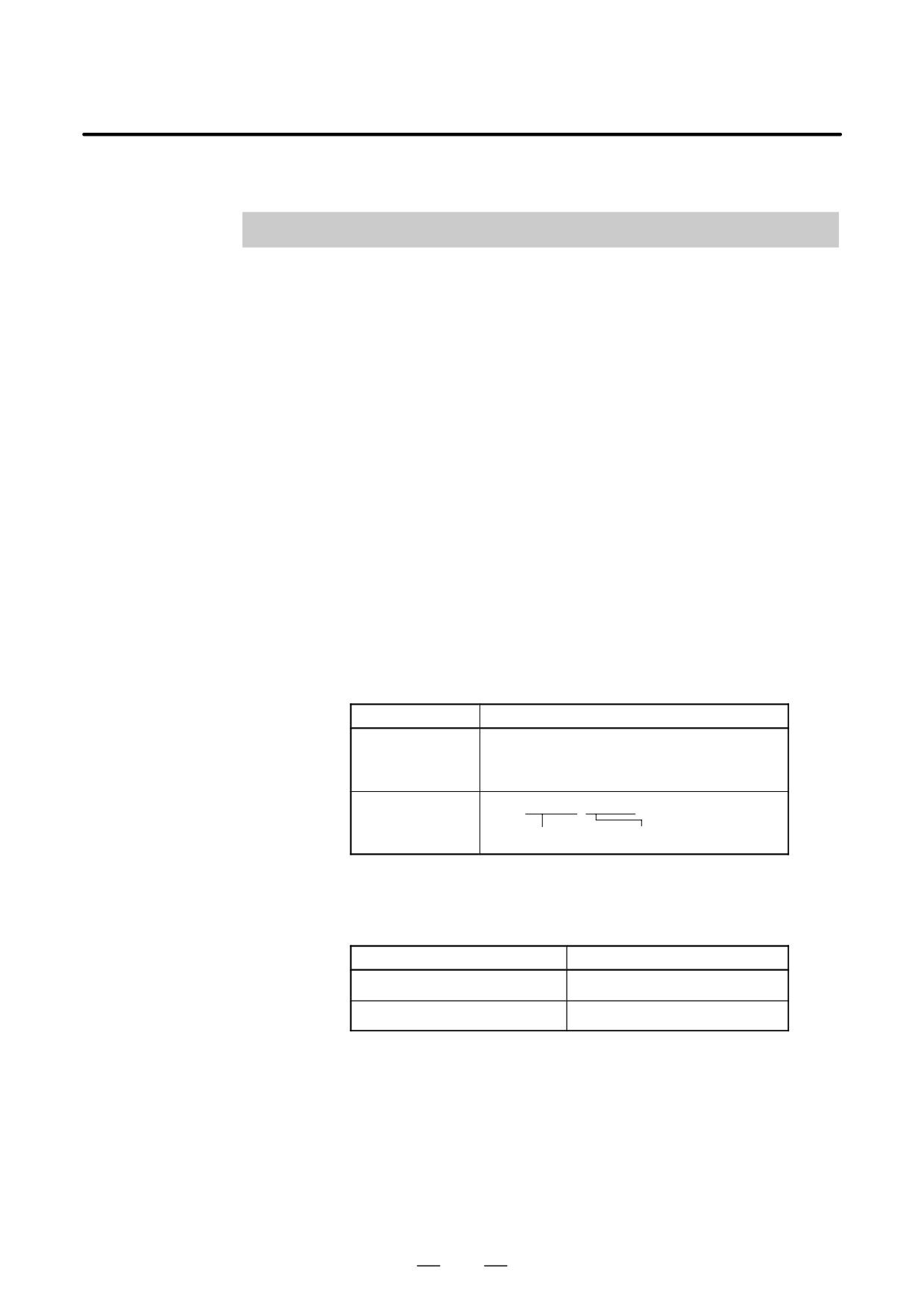
Table 18 (a) Subprogram call data format
CNC
Data format
Series 10/11
M98 Pfffff Lffff ;
P : Subprogram number
L : Repetition count
Series 0i
M98 Pffff jjjj ;
Repetition count Subprogram number
D Address for the canned
The Series 10/11 and Series 16/18/21 use different addresses for the repeat
cycle repetition count
count for canned cycles as listed in Table 18 (b).
Table 18 (b) Address for times of repetition of canned cycle
CNC
Address
Series 10/11
L
Series 0i
K
375
19. HIGH SPEED CUTTING
FUNCTIONS
PROGRAMMING
B-64124EN/01
HIGH SPEED CUTTING FUNCTIONS
19
376
19. HIGH SPEED CUTTING
B-64124EN/01
PROGRAMMING
FUNCTIONS
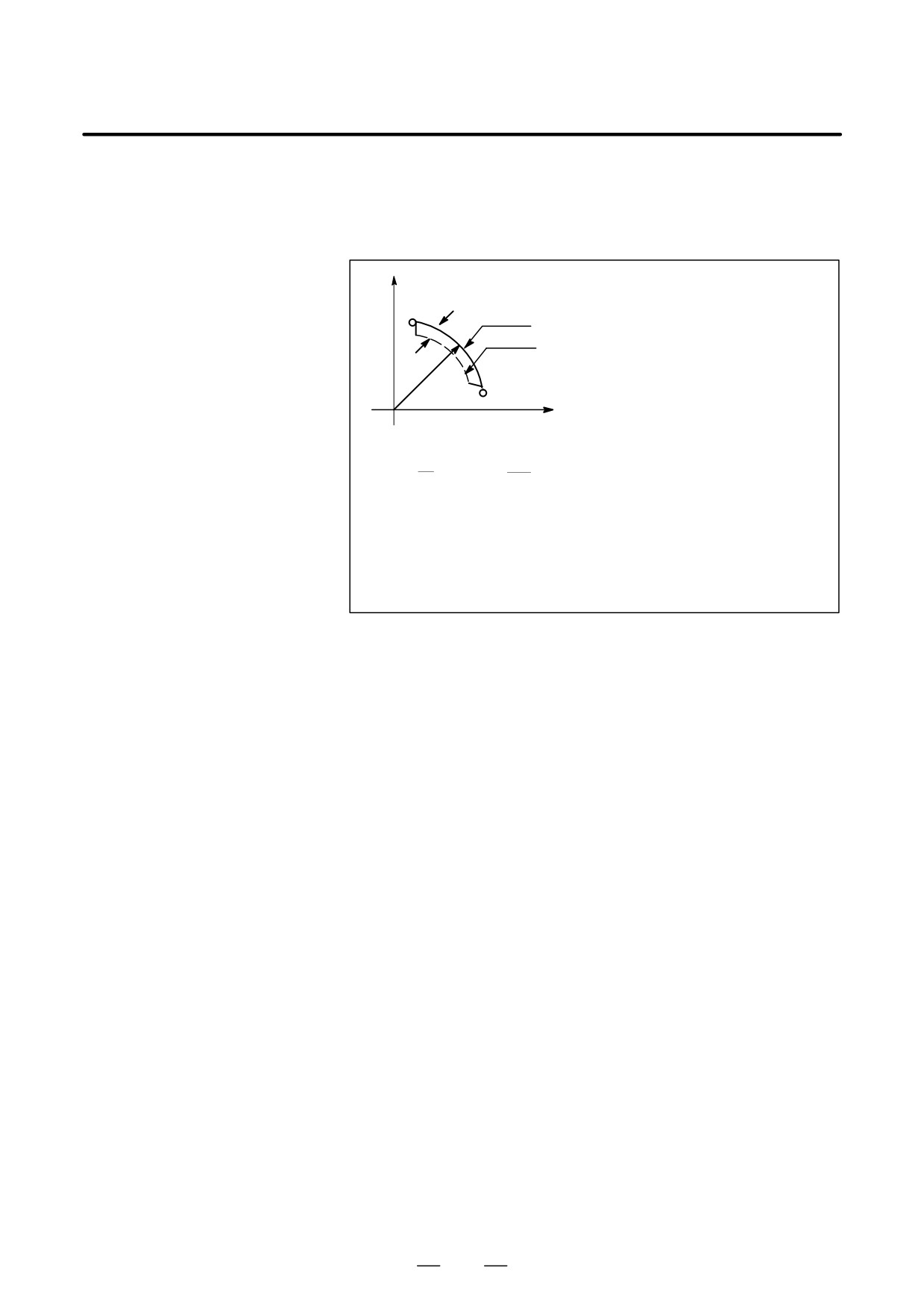
When an arc is cut at a high speed in circular interpolation, a radial error
19.1
exists between the actual tool path and the programmed arc. An
FEEDRATE
approximation of this error can be obtained from the following
CLAMPING BY ARC
expression:
RADIUS
Y
∆r:Error
Programmed path
Actual path
r
0
X
1
v2
∆r=
(T1
2+T22)
2
r
∆r
:
Maximum radial error (mm)
v
:
Feedrate (mm/s)
r
:
Arc radius (mm)
T1 : Time constant (s) for exponential acceleration/deceleration of
cutting feed
T2
:
Time constant of the servo motor (s)
When actual machining is performed, radius r of the arc to be machined
and permissible error ∆r are given. Then, maximum allowable feedrate
v (mm/min) is determined from the above expression.
The function for clamping the feedrate by the arc radius automatically
clamps the feedrate of arc cutting to the value set in a parameter. This
function is effective when the specified feedrate may cause the radial error
for an arc with a programmed radius to exceed the permissible degree of
error.
For details, refer to the relevant manual published by the machine tool
builder.
377

19. HIGH SPEED CUTTING
FUNCTIONS
PROGRAMMING
B-64124EN/01
This function is designed for high-speed precise machining. With this
19.2
function, the delay due to acceleration/deceleration and the delay in the
ADVANCED PREVIEW
servo system which increase as the feedrate becomes higher can be
CONTROL (G08)
suppressed.
The tool can then follow specified values accurately and errors in the
machining profile can be reduced.
This function becomes effective when advanced preview control mode is
entered.
For details, refer to the relevant manual published by the machine tool
builder.
Format
G08 P_
P1 : Turn on advanced preview control mode.
P0 : Turn off advanced preview control mode.
Explanations
D Available functions
In advanced preview control mode, the following functions are available:
(1) Linear acceleration/deceleration before interpolation
(2) Automatic corner deceleration function
For details on the above functions, see the Connection Manual (Function)
(B-64113EN-1). Each function, specific parameters are provided.
D Reset
Advanced preview control mode is canceled by reset.
Limitations
D G08 command
Specify G08 code only in a block.
D Functions that can be
In the advanced preview control mode, the functions listed below can be
specified
specified.
NOTE
To use a function other than the following functions, turn the
advanced preview control mode off, specify the desired
function, then turn the mode on again.
⋅ Inverse time feed
⋅ Axis control by the PMC
(Bits 4 (G8R) and 3 (G8C) of parameter No. 8004 can be set to also use
this function in the advanced preview control mode.)
⋅ Single direction positioning
⋅ Polar coordinate command
⋅ Helical interpolation
⋅ Rigid tapping
(Bit 5 (G8S) of parameter No. 1602 can be set to also use this function
in the look-ahead control mode. The serial spindle parameters must
also be set.)
378
19. HIGH SPEED CUTTING
B-64124EN/01
PROGRAMMING
FUNCTIONS
⋅
Program restart
⋅
External deceleration
⋅
Simple synchronous control
⋅
Sequence number comparison and stop
⋅
Position switch
(Bit 3 (PSF) of parameter No. 6901 can be set to also use this function
in the advanced preview control mode. Setting this parameter to 1
changes the timing when the signal is output. So, it may become
necessary to change the ladder.)
⋅
Cs contour control
(Bit 5 (G8S) of parameter No. 1602 can be set to also use this function
in the advanced preview control mode. The serial spindle parameters
must also be set.)
⋅
Constant surface speed control
⋅
Spindle synchronous control
⋅
Custom macro B
⋅
Arbitrary angle chamfering/corner rounding
⋅
Inch/metric conversion
⋅
Programmable mirror image
⋅
Canned cycle
⋅
Automatic corner override
(Only the internal circular cutting feedrate change is valid.)
⋅
Scaling
⋅
Coordinate system rotation
⋅
Workpiece coordinate system
⋅
Workpiece coordinate system preset
⋅
Cutter compensation C
⋅
Corner circular interpolation
⋅
Tool offset
⋅
Tool life management
⋅
Tool length measurement
⋅
Graphic display
⋅
Dynamic graphic display
⋅
Feed per revolution
379
19. HIGH SPEED CUTTING
FUNCTIONS
PROGRAMMING
B-64124EN/01
19.3
AI ADVANCED
PREVIEW CONTROL
FUNCTION/
AI CONTOUR
CONTROL FUNCTION
Overview
The AI advanced preview control/AI contour control function is provided
for high-speed, high-precision machining. This function enables
suppression of acceleration/deceleration delays and servo delays that
become larger with increases in the feedrate and reduction of machining
profile errors.
Look-ahead acceleration/deceleration before interpolation is enabled for
up to 20 blocks in AI advanced preview control or for up to 40 blocks in
AI contour control. This enables execution of smooth acceleration/
deceleration extending over multiple blocks and higher machining.
Explanation
This function is enabled by setting the AI advanced preview control or AI
contour control mode.
D Format
G05.1 Q _ ;
Q1 : AI advanced preview control/AI contour control mode on
Q0 : AI advanced preview control/AI contour control mode off
NOTE
1
Always specify G05.1 in an independent block.
2
The AI advanced preview control/AI contour control mode
is also canceled by a reset.
3
When the AI contour control option is installed, the AI
contour control mode is enabled.
380
19. HIGH SPEED CUTTING
B-64124EN/01
PROGRAMMING
FUNCTIONS
D Functions valid in the AI
The functions listed below are valid in the AI advanced preview
advanced preview
control/AI contour control mode:
control/AI contour
⋅ Look-ahead linear acceleration/deceleration before interpolation
control mode
⋅ Look-ahead bell-shaped acceleration/deceleration before interpolation
(The option of look-ahead bell-shaped acceleration/deceleration
before interpolation is required.)
⋅ Automatic corner deceleration
⋅ Feedrate clamping by acceleration
⋅ Feedrate clamping by arc radius
⋅ Block overlap
⋅ Advanced preview feed forward
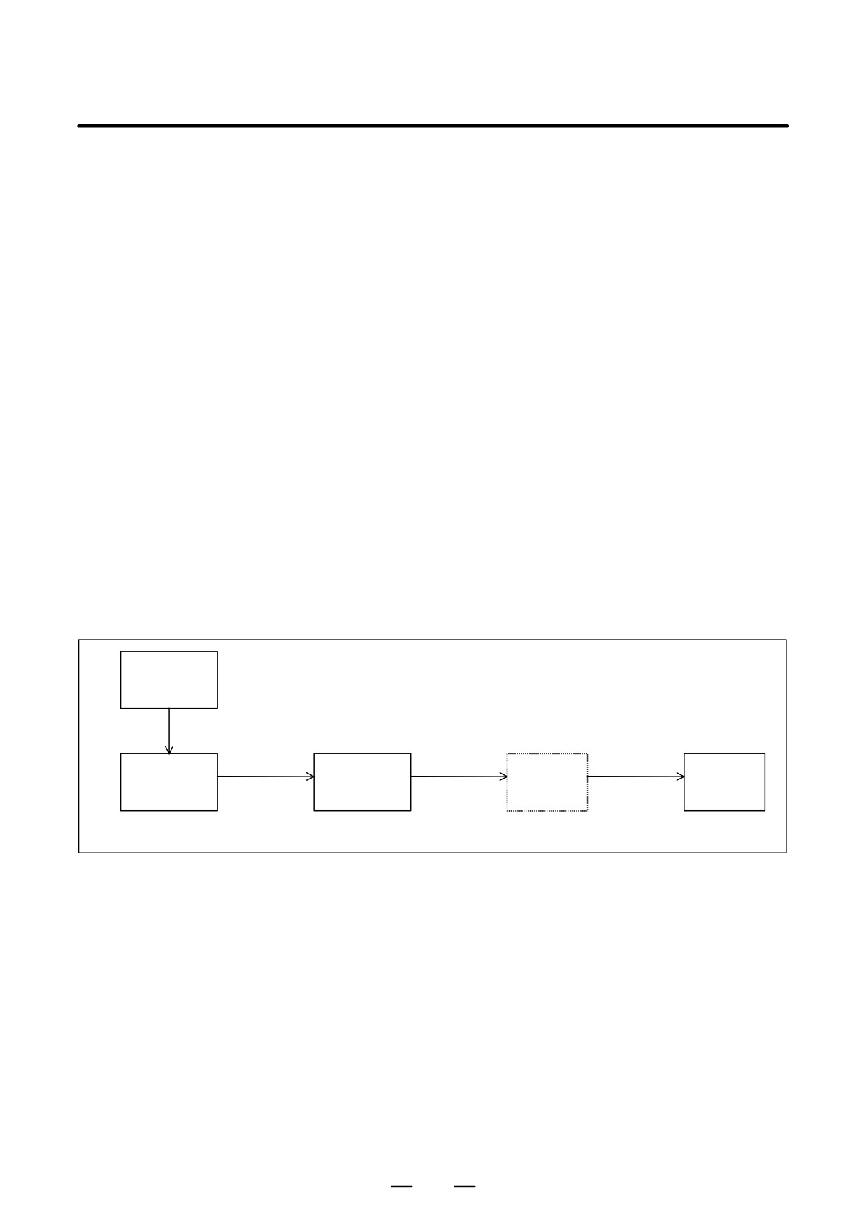
D Look-ahead linear
For a cutting feed command in the feed per minute mode, linear
acceleration/deceleration
acceleration/deceleration can be applied before interpolation, that is, for
before interpolation
the specified feedrate by reading up to 20 blocks (in the AI advanced
preview control mode) or 40 blocks (in the AI contour control mode) in
advance.
With acceleration/deceleration after interpolation, the
interpolated data is changed because acceleration/deceleration is applied
to the data. With acceleration/deceleration before interpolation, the
interpolated data cannot be changed by acceleration/deceleration because
acceleration/ deceleration is applied to the feedrate data before
interpolation. For this reason, the interpolated data can always be applied
to the specified straight line or curve to eliminate machining profile errors
caused by acceleration/deceleration delays.
Linear accelera-
tion/deceleration
before
interpolation
Specified
Distribution
Acceleration/
feedrate
pulse
Feedrate
Interpolation
deceleration
Servo
calculation
calculation
after
control
interpolation
Linear interpolation,
circular interpolation, etc.
381
19. HIGH SPEED CUTTING
FUNCTIONS
PROGRAMMING
B-64124EN/01
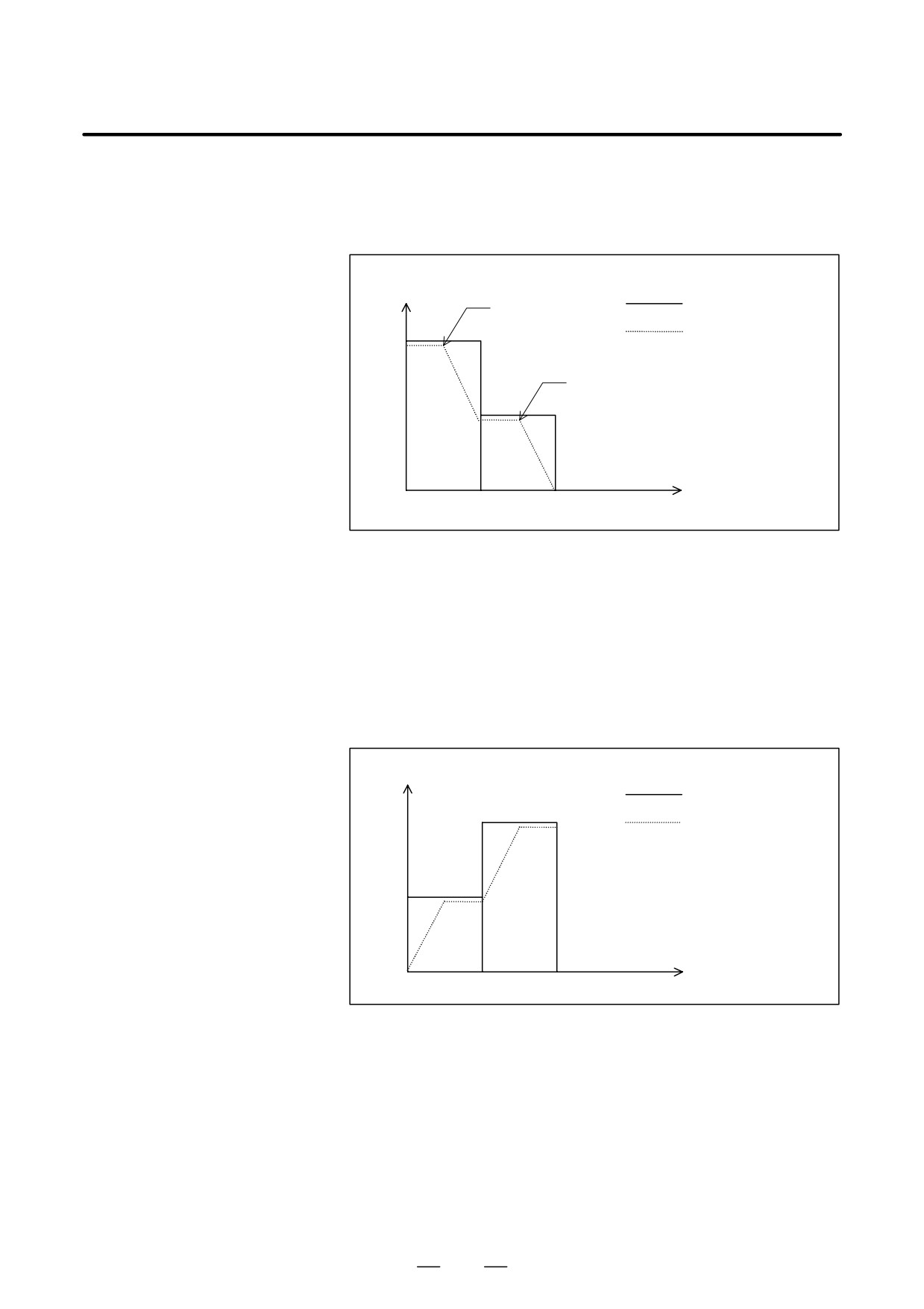
(Example of deceleration)
Deceleration is started in a prior block so that the feedrate specified for
the target block is reached at the execution.
Feedrate
Specified feedrate
Point1
Feedrate determined by
F3
acceleration/deceleration
beforeinterpolation
Point2
F2
F1
Time
N1
N2
To decelerate from feedrate F3 to F2, deceleration must start with point 1.
To decelerate from feedrate F2 to F1, deceleration must start with point 2.
Multiple blocks can be read in advance to perform deceleration extending
over several blocks.
(Example of acceleration)
Acceleration is performed so that the feedrate specified for the target
block is reached at the execution.
Feedrate
Specified feedrate
Feedrate determined by
F3
acceleration/deceleration
beforeinterpolation
F2
F1
Time
N1
N2
382
19. HIGH SPEED CUTTING
B-64124EN/01
PROGRAMMING
FUNCTIONS
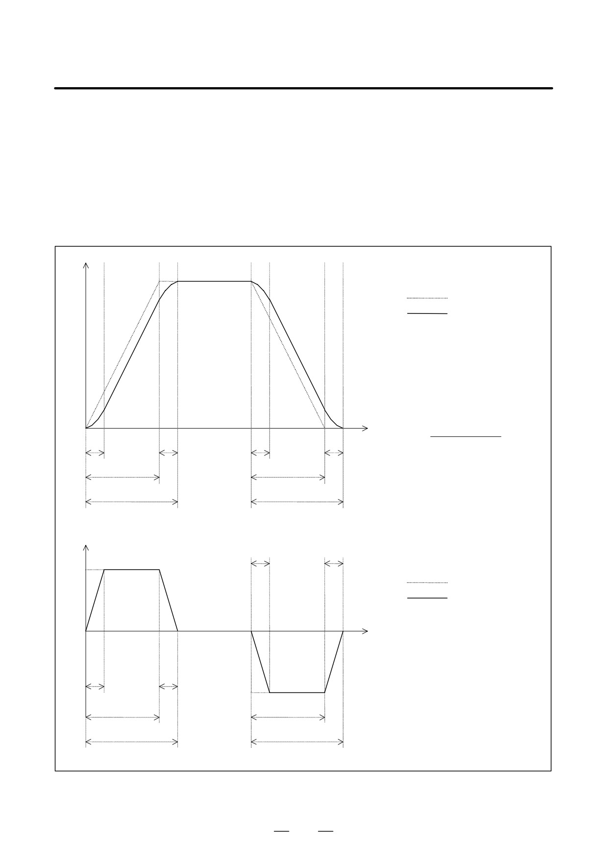
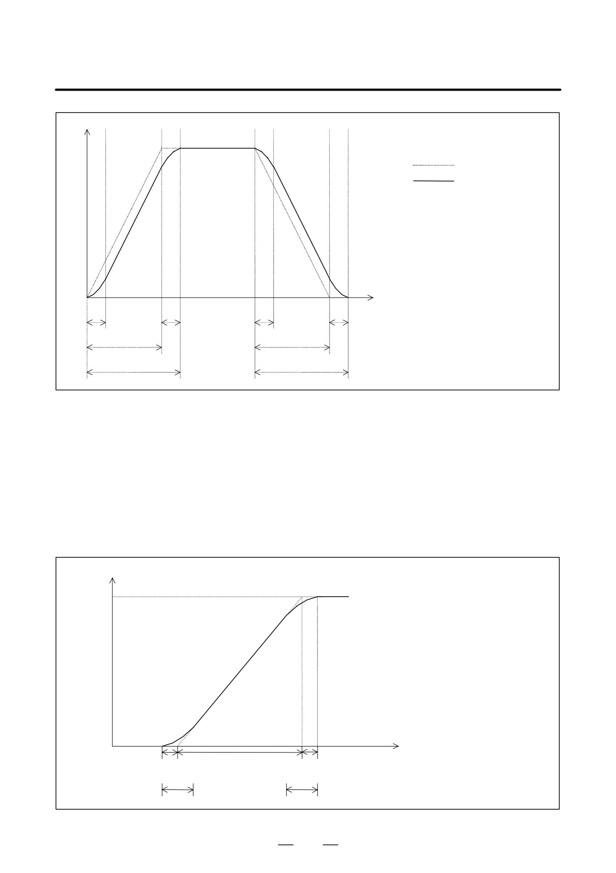
D Look-ahead bell-shaped
Linear acceleration/deceleration before interpolation for cutting feed in
acceleration/deceleration
the AI advanced preview control/AI contour control mode can be changed
before interpolation
to bell-shaped acceleration/deceleration before interpolation. With
bell-shaped acceleration/deceleration before interpolation, smooth
acceleration/deceleration can be applied to the cutting feedrate to reduce
the shock on the machine by fluctuations in acceleration that are involved
in changes in the cutting feedrate.
To use this function, the option of look-ahead bell-shaped acceleration/
deceleration before interpolation is required.
Feedrate
Linear acceleration/
deceleration
Bell-shaped acceleration/
deceleration
ta Depends on the linear acceleration.
tb Time constant for bell-shaped
acceleration/deceleration
tc Bell-shapedacceleration/
deceleration time
tc = ta + tb
ta is not constant and depends
on the specified feedrate.
Specified feedrate
Time
ta =
tb
tb
tb
tb
Linear acceleration
tb is constant.
ta
ta
tc
tc
Acceleration
tb
tb
Linear acceleration/
deceleration
Bell-shaped acceleration/
deceleration
ta Depends on the linear acceleration.
Time
tb Time constant for bell-shaped
acceleration/deceleration
tc Bell-shapedacceleration/
deceleration time
tb
tb
12.
tc = ta + tb
ta
ta
tc
tc
383
19. HIGH SPEED CUTTING
FUNCTIONS
PROGRAMMING
B-64124EN/01
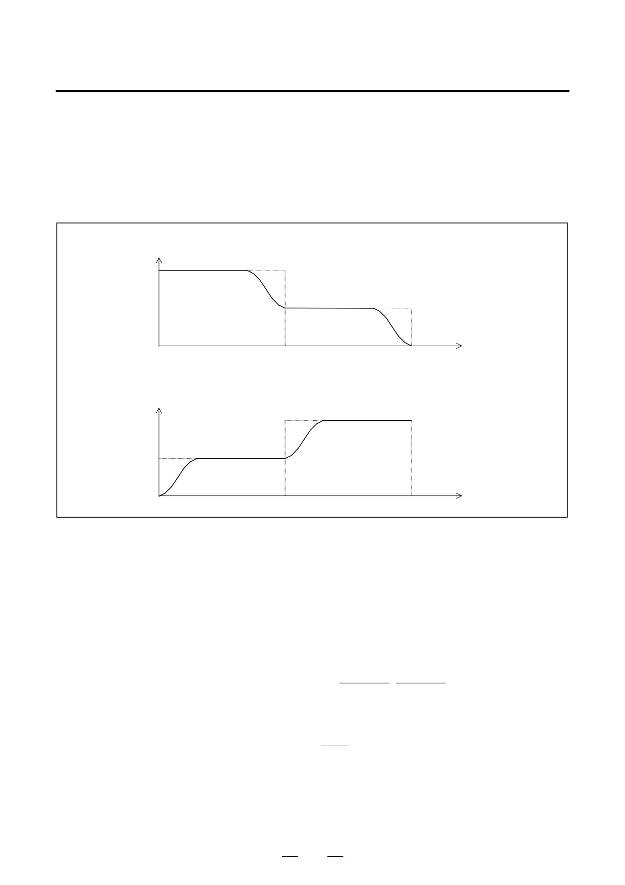
When the feedrate is changed, deceleration and acceleration are
performed as follows:
For deceleration: Bell-shaped deceleration is started in the preceding
block so that deceleration terminates by the beginning of the block in
which the feedrate is changed.
For acceleration: Bell-shaped acceleration is started after the
beginning of the block in which the feedrate is changed.
Deceleration
Fa
Fb
Time
N1
N2
Acceleration
Feedrate
Fb
Fa
Time
N1
N2
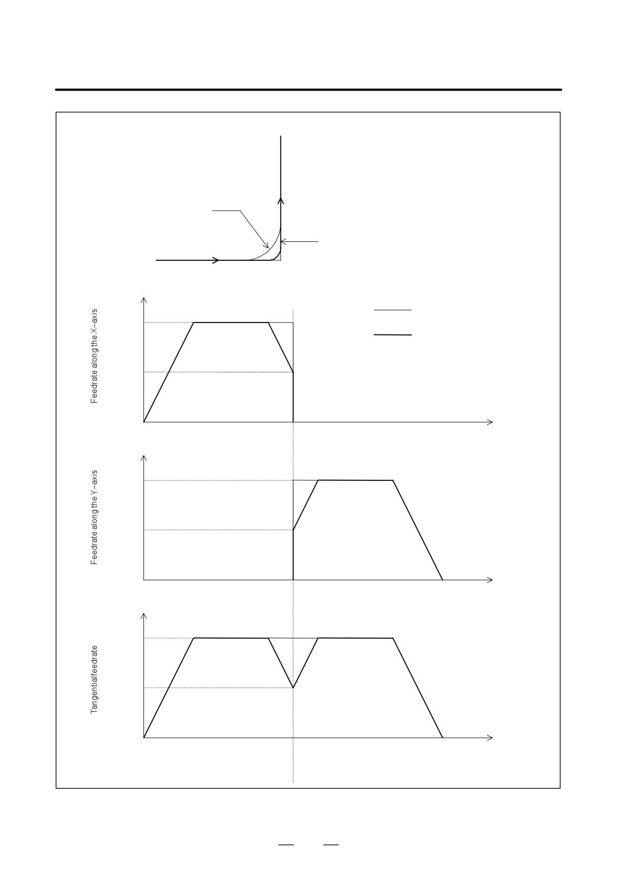
D Automatic corner
Between contiguous two blocks, the feedrate difference for an axis may
deceleration
exceed the setting (parameter No. 1783). In this case, the feedrate at the
corner is calculated as follows based on the axis for which the ratio of the
actual feedrate difference to the allowable feedrate difference is the
largest. Deceleration is performed so that the feedrate is reached at the
interface of the blocks.
The change in the feedrate for each axis (Vx, Vy, ...) during movement at
the specified feedrate F is compared with the setting of parameter No.
1783 (Vprm-x, Vprm-y, ...). If the change in the feedrate for any axis
exceeds the setting of the parameter, the following expression is used:
Vx
Vy
Rmax + maxƪ
,
,,,ƫ
Vprm * x
Vprm * y
The required feedrate (Fc) is obtained as follows and deceleration is
performed at the corner:
1
Fc + F
Rmax
For example, assume that the tool move direction changes by 90 degrees
from movement along the X-axis to that along the Y-axis. Also assume
that the specified feedrate is 1000 mm/min and the allowable feedrate
difference
(parameter No. 1783) is
500 mm/min. Deceleration is
performed as shown in the figure below:
384
19. HIGH SPEED CUTTING
B-64124EN/01
PROGRAMMING
FUNCTIONS
N1 G01 G91 X100. F1000 ;
N2 Y100. ;
N2
Tool path when deceleration
is not performed at the corner
Tool path when deceleration is
performed at the corner
N1
Feedrate
When deceleration is not performed
F1000
at the corner
When deceleration is performed
at the corner
F500
N1
Time
Feedrate
F1000
F500
N2
Time
Feedrate
F1000
F500
N1
N2
Time
385
19. HIGH SPEED CUTTING
FUNCTIONS
PROGRAMMING
B-64124EN/01
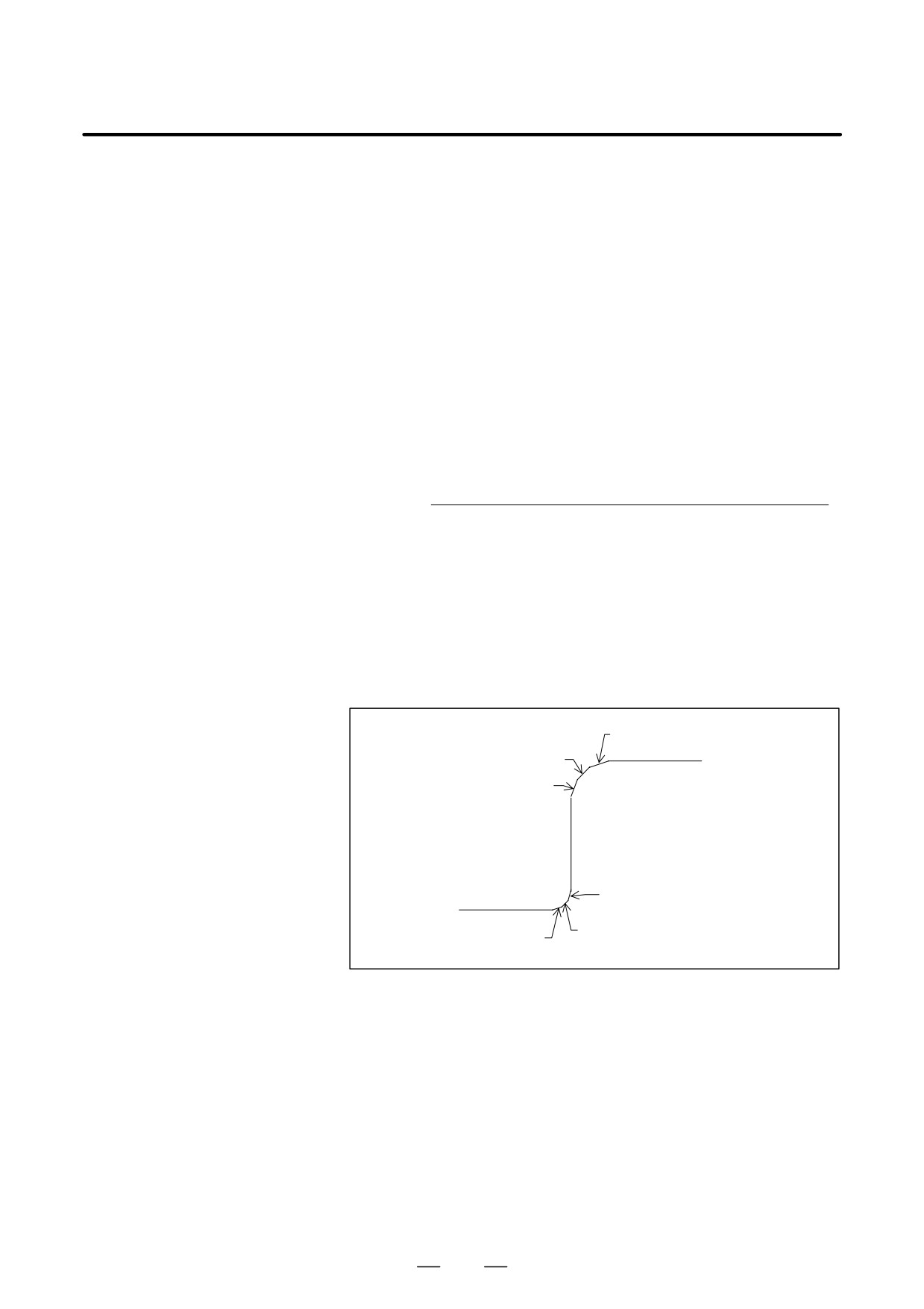
D Feedrate clamping by
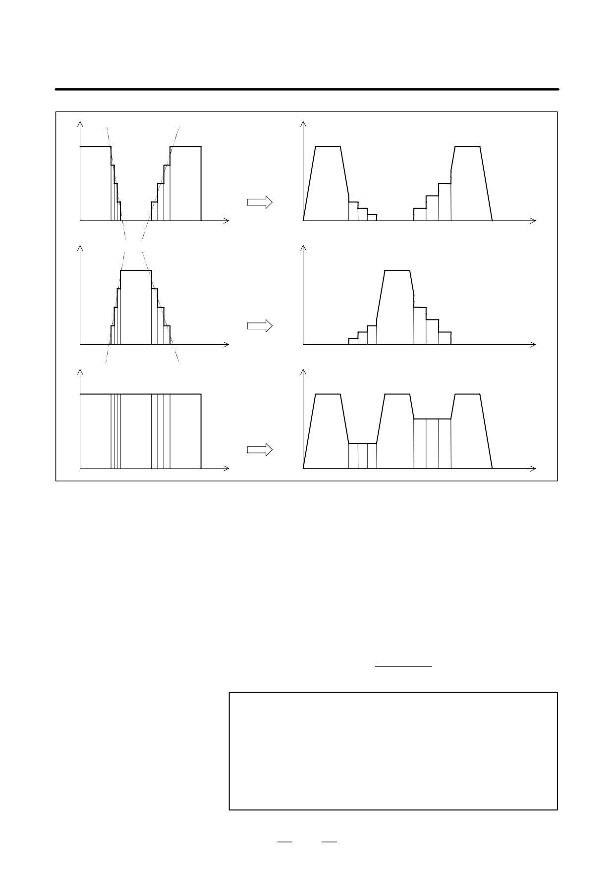
When continuous minute straight lines form curves as shown in the
acceleration
example in the figure below, the feedrate difference for each axis at each
corner is not so large. For this reason, deceleration according to the
feedrate difference is not effective. Continuous small feedrate differences
make a large acceleration for each axis as a whole, however.
In this case, deceleration is performed to suppress the shock on the
machine and machining errors caused by too large acceleration. The
feedrate is decreased so that the acceleration for each axis that is obtained
using the expression below does not exceed the allowable acceleration
setting for all axes.
The allowable acceleration is set based on the maximum cutting feedrate
(parameter No. 1432) and time required to reach the feedrate (parameter
No. 1785).
Acceleration for each axis =
Feedrate difference for each axis at each corner
maxƪTraveldistanceinprecedingblock
,Traveldistanceinfollowingblockƫ
F
F
The decreased feedrate is obtained for each corner. The decreased feedrate
obtained at the start or end point of the block, whichever is lower, is used
as the actual feedrate.
(Example) In the example below, deceleration is performed because the
acceleration (gradient of each dotted line in the feedrate
graphs) from N2 to N4 and from N6 to N8 is too large.
N8
N7
N9
N6
N5
N4
N1
N3
N2
386
19. HIGH SPEED CUTTING
B-64124EN/01
PROGRAMMING
FUNCTIONS
N1
N5
N9
N1
N5
N9
D Feedrate clamping by
The maximum allowable feedrate v for an arc of radius r specified in a
arc radius
program is calculated using the arc radius R and maximum allowable
feedrate V (setting of a parameter) for the radius as follows so that the
acceleration in an arc block does not exceed the allowable value. If the
specified feedrate exceeds the feedrate v, the feedrate is automatically
clamped to the feedrate v.
Maximum allowable feedrate +V2
R
R : Arc radius
V : Feedrate for arc radius R
then, the maximum allowable feedrate v for an arc of radius r can be
obtained using the following expression:
Ǹ
v+
(rńR) V
NOTE
As the specified arc radius becomes smaller, the maximum
allowable feedrate v becomes lower. If the maximum
allowable feedrate v is lower than the setting of parameter
No. 1732 (lower feedrate limit for feedrate clamping by arc
radius), it can be assumed to be the setting of the parameter
to prevent the maximum allowable feedrate from becoming
too low.
387
19. HIGH SPEED CUTTING
FUNCTIONS
PROGRAMMING
B-64124EN/01
D Rapid traverse
By setting the corresponding parameter, the linear or non-linear
interpolation type can be selected. (In the AI nano contour control mode,
the non-linear interpolation type cannot be selected.)
When the linear interpolation type is selected, acceleration/deceleration
is performed before interpolation and linear interpolation type
positioning is used for movement. For acceleration/deceleration, linear
or bell-shaped acceleration/deceleration can be selected by setting the
corresponding parameter.
The feedrate during movement and acceleration for acceleration/deceleration
before interpolation are obtained as follows:
(1) Feedrate during movement
The minimum value obtained using the following expression for each
axis along which movement is done is used as the feedrate during
movement:
Rapid traverse rate for each axis (parameter No. 1420) =
Amount of travel in block
Amount of travel for each axis
(2) Acceleration for acceleration/deceleration before interpolation
D For linear acceleration/deceleration
The minimum value obtained using the following expression for each
axis along which movement is done is used as the acceleration for linear
acceleration/deceleration before interpolation during movement:
Rapid traverse rate for each axis (parameter No. 1420)
Time constant for each axis (parameter No. 1620)
Amount of travel in block
Amount of travel for each axis
D For bell-shaped acceleration/deceleration
The time constant set in parameter No.
1621 (time constant for
bell-shaped acceleration/deceleration for rapid traverse for each axis) for
the axis for which the minimum value is obtained using the above
expression is applied to the feedrate obtained using the above
acceleration.
388
19. HIGH SPEED CUTTING
B-64124EN/01
PROGRAMMING
FUNCTIONS
Feedrate
Linear acceleration/
deceleration
Bell-shaped acceleration/
deceleration
ta Depends on the linear acceleration.
tb Time constant for bell-shaped
acceleration/deceleration
tc Bell-shapedacceleration/
deceleration time
tc = ta + tb
The value of ta is not constant and
depends on the rapid traverse rate
and the time constant of the rapid
traverse rate for the specified axis.
Time
tb
tb
tb
tb
The value of tb depends on the axis.
ta
ta
tc
tc
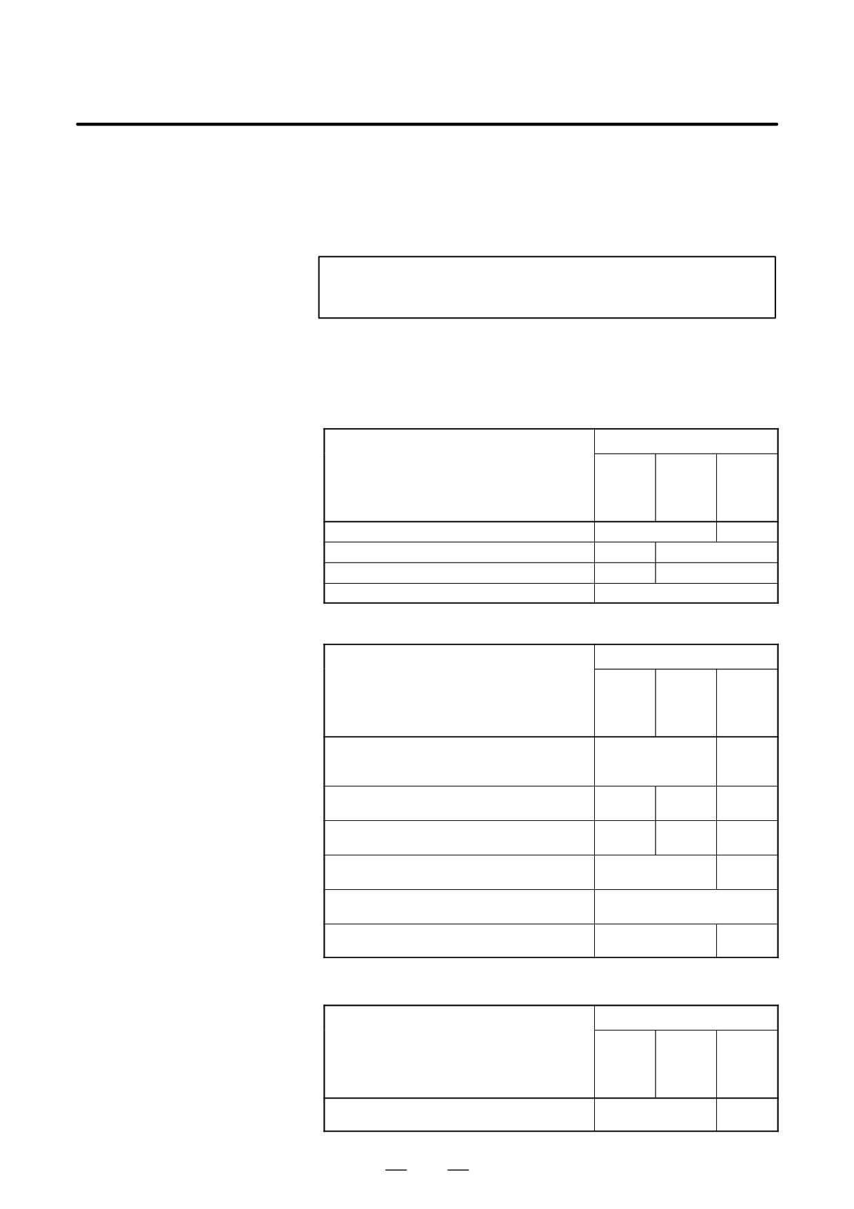
If the feedrate during movement is F, the acceleration for linear
acceleration/deceleration is A, the time constant for bell-shaped
acceleration/deceleration is T, the time required for acceleration/
deceleration can be obtained as follows:
Time required for acceleration/deceleration
= F/A
(linear acceleration/deceleration)
= F/A+T (bell-shaped acceleration/deceleration)
Feedrate
F
F/A : Time required for linear acceleration
T
: Time required for rounding the corner
Time
T/2
F/A
T/2
T
T
389
19. HIGH SPEED CUTTING
FUNCTIONS
PROGRAMMING
B-64124EN/01
When the non-linear interpolation type is selected, movement is
performed at the feedrate set in parameter No.
1420 with
acceleration/deceleration set in parameter No. 1620. The corresponding
value can be set in parameter No.
1621 to select bell-shaped
acceleration/deceleration.
NOTE
Rapid traverse block overlap is disabled.
D Corresponding
In the following tables, AI control means the AI advanced preview
parameter numbers in
control/AI contour control mode.
the normal mode,
(1) Parameters related to linear acceleration/deceleration before
advanced preview
interpolation
control mode, and AI
Parameter number
advanced preview
control/AI contour
Ad-
Parameter
control mode
vanced
AI
Normal
preview
contour
control
Acceleration/deceleration type (A or B)
FWB/1602#0
None
Parameter 1 for setting the acceleration
1630
1770
Parameter 2 for setting the acceleration
1631
1771
Feedrate at which an overtravel alarm occurs
1784
(2) Parameters related to automatic corner deceleration
Parameter number
Ad-
Parameter
vanced
AI
Normal
preview
contour
control
Method for determining whether to perform
CSD/1602#4
None
automatic corner deceleration (angle/fee-
drate difference)
Lower feedrate limit (control according to the
1778
1777
None
angle)
Angle at which automatic corner deceleration
1740
1779
None
is performed (control according to the angle)
Allowable feedrate difference for all axes
1780
None
(control according to the feedrate difference)
Allowable feedrate difference for each axis
1783
(control according to the feedrate difference)
Acceleration/deceleration type
FWB/1602#0
None
(Type A/Type B)
(3) Parameter related to feedrate clamping by acceleration
Parameter number
Ad-
Parameter
vanced
AI
Normal
preview
contour
control
Parameter for determining the allowable ac-
None
1785
celeration
390

19. HIGH SPEED CUTTING
B-64124EN/01
PROGRAMMING
FUNCTIONS
(4) Parameters related to feedrate clamping by arc radius
Parameter number
Ad-
Parameter
vanced
AI
Normal
preview
contour
control
Arc radius corresponding to the upper fee-
1731
drate limit
Upper feedrate limit at arc radius R
1730
Lower clamped feedrate limit
1732
(5) Other parameters
Parameter number
Ad-
Parameter
vanced
AI
Normal
preview
contour
control
Precision of radius errors in circular interpola-
PCIR1/3403#0
None
tion
Maximum cutting feedrate (common to all
1422
1431
1422
axes)
Maximum cutting feedrate (for each axis)
1430
1432
Rapid traverse movement type*
LRP/1401#1
AIR/
7054#1
LRP/
1401#1
Time constant for bell-shaped acceleration/
1621
RBL/
deceleration for rapid traverse
1603#6
1621
Arc radius corresponding to the upper fee-
1731
drate limit
391

19. HIGH SPEED CUTTING
FUNCTIONS
PROGRAMMING
B-64124EN/01
Alarms
Num-
Message
Description
ber
5110
IMPROPER G CODE
An unspecifiable G code was specified in
the AI advanced preview control/AI con-
(G05.1 Q1 MODE)
tour control mode.
5111
IMPROPER MODAL
An unavailable modal G code was found
G CODE
when the AI advanced preview control/AI
contour control mode was specified.
(G05.1 Q1)
5112
G08 CAN NOT BE
The look-ahead control command (G08)
COMMANDED
was specified in the AI advanced preview
control/AI contour control mode.
(G05.1 Q1)
5114
CAN NOT ERROR IN
Intervention by manual operation was per-
MDI MODE
formed during execution of the G28, G30,
or G53 command (linear interpolation
(G05.1 Q1)
type) in the AI advanced preview control/
AI contour control mode. After that, auto-
matic operation was restarted at a position
other than the stop position.
5156
ILLEGAL AXIS
In the AI advanced preview control/AI con-
OPERATION
tour control mode, the controlled axis
selection signal (PMC axis control)
(AICC)
changed.
In the AI advanced preview control/AI con-
tour control mode, the simple synchronous
axis selection signal changed.
5157
PARAMETER 0
The setting of the parameter for specifying
the maximum cutting feedrate (No. 1422,
(AICC)
1432, or 1420) is 0.
The setting of the parameter for specifying
acceleration/deceleration before interpola-
tion (No. 1770 or 1771) is 0.
Notes
1) The advanced preview control function (G08P1) can also be specified.
2) When the total distance of blocks read in advance reaches the distance
for decelerating from the current feedrate, deceleration is started.
When look-ahead operation proceeds and the total distance of blocks
increases by termination of deceleration, acceleration is started again.
If a series of blocks with a small amount of travel are specified, the
deceleration and acceleration may be alternated, which prevents the
feedrate from being constant. In this case, specify a lower feedrate.
3) When the dry run signal is inverted from ”0” to ”1” or from ”1” to ”0”
during movement along an axis, acceleration/deceleration is
performed to the specified feedrate without deceleration to feedrate 0.
4) If a non-movement block or one-shot G code command such as G04
is found in the AI advanced preview control/AI contour control mode,
the movement is decelerated and temporarily stopped in the preceding
block.
5) For acceleration/deceleration after interpolation, use linear or
bell-shaped acceleration/deceleration. Exponential acceleration/
deceleration cannot be used.
392

19. HIGH SPEED CUTTING
B-64124EN/01
PROGRAMMING
FUNCTIONS
D Specifications
Axis control
f : Can be specified.
: Cannot be specified.
Name
Function
Number of controlled axes
3 to 4
Number of simultaneously con-
Up to 4
trolled axes
Axis name
The basic three axes are fixed to X, Y, and Z.
Other axes are any of U, V, W, A, B, and C.
Least input increment
0.001 mm, 0.001 deg, 0.0001 inch
One-tenth input increment
0.0001 mm, 0.0001 deg, 0.00001 inch
One-tenth input increment for each axis cannot be
used.
Simple synchronous control
f
However, switching between synchronous and
normal operation cannot be performed during
automatic operation (when the automatic op-
eration signal (OP) is set to 1) regardless of
whether the AI advanced preview control/AI
contour control mode is set. In this case,
switching causes a PS213 alarm.
Angular axis control
Tandem control
f
However, full preloading is not allowed.
Inch/metric conversion
f
(*1)
(G20, G21)
Interlock
f
Interlock for each axis
f
Movement along all axes stops.
To stop movement only along the interlock axis
in non-linear interpolation type positioning, set
bit 5 (AIL) of parameter No. 7054 to 1 and bit 4
(XIK) of parameter No. 1002 to 0.
Machine lock
f
When the machine lock signal for each axis
(MLK1 to MLK8) is turned on or off, accelera-
tion/deceleration is not applied to the axis for
which machine lock is performed.
Stroke limit check before move
Mirror image
f
Stored pitch error compensation
f
Position switch
f
Set bit 3 (PSF) of parameter No. 6901 to 1.
When this parameter is set to 1, the signal out-
put timing changes.
Abnormal load detection
f
Manual handle interruption
f
Manual handle interruption is disabled during
switching to the AI advanced preview control/AI
contour control mode.
External pulse synchronization
Interpolation functions
f : Can be specified.
: Cannot be specified.
Name
Function
Positioning (G00)
f
Single direction positioning (G60)
f To perform single direction positioning in the AI
advanced preview control/AI contour control
mode, set bit 4 (ADP) of parameter No. 7055 to
1.
Exact stop (G09)
f
Exact stop mode (G61)
f
Tapping mode (G63)
f
Linear interpolation (G01)
f
Circular interpolation (G02, G03)
f (Circular interpolation for multiple quadrants is
enabled.)
393

19. HIGH SPEED CUTTING
FUNCTIONS
PROGRAMMING
B-64124EN/01
Name
Function
Dwell (G04)
f
(Dwell with the time in seconds or speed speci-
fied) For dwell with the speed specified, anoth-
er option is required.
Cylindrical interpolation (G07.1)
Helical interpolation (G02, G03)
f
(Circular interpolation + linear interpolation for
up to two axes)
Specify the feedrate including the helical axis in
the feedrate command.
Threading and synchronous feed
(G33)
Skip function (G31)
f
(*2)
High-speed skip function (G31)
f
(*2)
Multistage skip function (G31 Px)
f
(*2)
Reference position return (G28)
f
(*2)
To execute G28 in the status in which the refer-
ence position is not established, set bit 2 (ALZ)
of parameter No. 7055 to 1.
Reference position return check
f
(*2)
(G27)
2nd, 3rd, and 4th reference posi-
f
(*2)
tion return (G30)
Normal direction control
f
Set bit 2 (ANM) of parameter No. 5484 to 1.
(G41.1, G42.1)
Continuous dressing
In-feed control (G161)
Index table indexing
f
(*2)
To set follow-up of the index table indexing
axis (fourth axis), set bit 7 (NAH4) of parameter
No. 1819 and bit 0 (NMI4) of parameter No.
7052 to 1.
Feed functions
f : Can be specified.
: Cannot be specified.
Name
Function
Rapid traverse rate
Up to 240 m/min (0.001 mm)
Up to 100 m/min (0.0001 mm)
Rapid traverse rate override
F0, 25, 50, 100 %
Rapid traverse rate override in in-
0 to 100 %
crements of 1%
Feed per minute (G94)
f
Feed per revolution (G95)
Cutting feedrate clamp
f
Bell-shapedacceleration/decel-
f
eration for rapid traverse
Linearacceleration/deceleration
f
after cutting feed interpolation
Bell-typeacceleration/decelera-
f
tion after cutting feed interpolation
Linearacceleration/deceleration
f (Up to 20 blocks are read in advance in the AI
before cutting feed interpolation
advanced preview control mode.)
(Up to 40 blocks are read in advance in the AI
contour control mode.)
Feedrate override
0 to 254 %
Single-digit F code feed
f To enable feedrate change using a manual
handle, set bit 1 (AF1) of parameter No. 7055
to 1.
Inverse time feed (G93)
f
Override cancel
f
394

19. HIGH SPEED CUTTING
B-64124EN/01
PROGRAMMING
FUNCTIONS
Name
Function
External deceleration
f
Look-ahead bell-shaped accel-
f
eration/deceleration beforeinter-
polation
Program input
f : Can be specified.
: Cannot be specified.
Name
Function
Control in/control out command ()
f
Optional block skip command
f
(/n: n is a number.)
Absolute command (G90)/
f
incremental command (G91)
Decimal point programming/pock-
f
et calculator type decimal point
programming
10-fold input unit
f
Plane selection (G17, G18, G19)
f
Rotation axis specification
f
Rotation axis roll over
f
Polar coordinate command (G16)
Local coordinate system (G52)
f
(*2)
Machine coordinate system (G53)
f
(*2)
Workpiece coordinate system
f
(G54 to G59)
(G54.1Pxx)
Workpiece coordinate system
f
(*2)
(G92)
Workpiece coordinate system pre-
f
(*2)
set (G92.1)
Arbitrary angle chamfering/corner
rounding
Programmable data input (G10)
f
(*2)
Only the tool offset value, workpiece origin off-
set, and parameter can be changed.
Custom macro B
f
See the description of ”Notes on using custom
macros.”
Addition of custom macro com-
f
mon variables
Pattern data input
Interruption type custom macro
Canned cycle (G73 to G89)
f
(*2)
Initial level return (G98)/
f
(*2)
point R level return (G99)
Small hole peck drilling cycle
(G83)
Arc radius R programming
f
Automatic corner override (G62)
f
Set bit 0 (ACO) of parameter No. 7055 to 1.
Automatic corner deceleration
f
Feedrate clamping by arc radius
f
Scaling (G51)
f
Coordinate system rotation (G68)
f
Programmable mirror image
f
(G51.1)
F10/11 tape format
f
395

19. HIGH SPEED CUTTING
FUNCTIONS
PROGRAMMING
B-64124EN/01
Auxiliary functions/spindle-speed functions
f : Can be specified.
: Cannot be specified.
Name
Function
Miscellaneous function (Mxxxx)
f The function code and function strobe signals
are output only.
Second auxiliary function (Bxxxx)
f The function code and function strobe signals
are output only.
High-speed M/S/T/B interface
f
Multiple miscellaneous function
f
specification
Spindle-speed function (Sxxxx)
f
Spindle synchronous control
f
Rigid tapping
f
(*2)
Set bit 5 (G8S) of parameter No. 1602 or bit 3
(ACR) of parameter No. 7051 to 1.
Tool compensation functions
f : Can be specified.
: Cannot be specified.
Name
Function
Tool function (Txxxx)
f The function code and function strobe signals
are output only.
Tool length compensation
f
(G43, G44, G49)
Tool offset (G45 to G48)
Cutter compensation C
f
(G40, G41, G42)
Tool life management
Automatic tool length measure-
ment
Other functions
f : Can be specified.
: Cannot be specified.
Name
Function
Cycle start/feed hold
f
Dry run
f
Single block
f
Sequence number comparison
f
and stop
Program restart
f For the time constant for acceleration/decelera-
tion during movement to the restart position,
the following parameters are used:
When exponential acceleration/deceleration is
used: Parameter Nos. 1624 and 1625
Whenlinear/bell-shapedacceleration/decel-
eration is used: Parameter No. 1622
To set the acceleration/deceleration type, use
bits 0 and 1 of parameter No. 1610.
Rigid tapping return
Macro executor
(execution macro)
MDI operation
f
Manualintervention
f
NOTE
The above tables include a function that another option is
required for specifying.
1
Multiple blocks are not read in advance.
396

19. HIGH SPEED CUTTING
B-64124EN/01
PROGRAMMING
FUNCTIONS
D Conditions for setting the
When G05.1 Q1 is specified, the modal G codes must be set as listed
AI advanced preview
below. If one of these conditions is satisfied, a PS5111 alarm occurs.
control/AI contour
G code(s)
Description
control mode
G00
Positioning
G01
Linear interpolation
G02
Circular interpolation (CW)
G03
Circular interpolation (CCW)
G15
Polar coordinate command cancel
G40
Cutter compensation cancel
G40.1
Normal direction control cancel mode
G49
Tool length compensation cancel
G50
Scaling cancel
G50.1
Programmable mirror image cancel
G64
Cutting mode
G67
Macro modal call cancel
G69
Coordinate system rotation cancel
G80
Canned cycle cancel
G94
Feed per minute
G97
Constant surface speed control cancel
G160
In-feed control function cancel
397
19. HIGH SPEED CUTTING
FUNCTIONS
PROGRAMMING
B-64124EN/01
19.4
LOOK-AHEAD
BELL-SHAPED
ACCELERATION/DEC
ELERATION BEFORE
INTERPOLATION
TIME CONSTANT
CHANGE FUNCTION
General
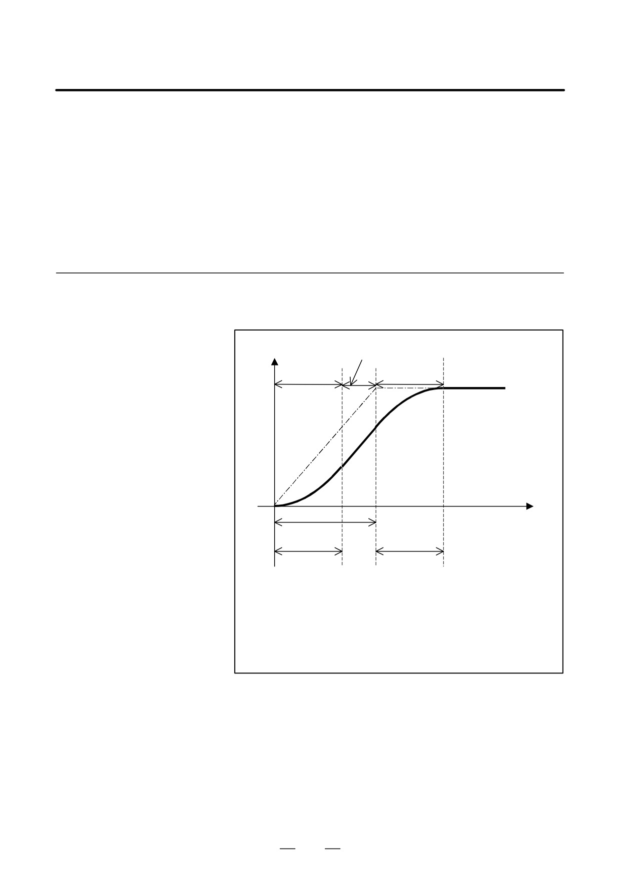
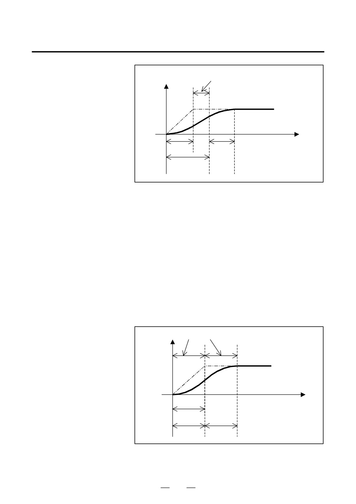
In Look-ahead bell-shaped acceleration/deceleration before
interpolation, the speed during acceleration/deceleration is as shown in
the figure below.
Linear
Speed
acceleration/deceleration
Non-linear
Non-linear
acceleration/deceleration
acceleration/deceleration
Specified
speed
Time
T1
T2
T2
T1: Time determined from the specified speed and the specified acceleration
Specified acceleration:
In case of AI contour control
Parameter No.1770/Parameter No.1771
T2: Acceleration change time
In case of AICC : Parameter No.1772
Fig.19.4 (a)
The time T1, shown above, varies with the specified speed. If the
specified speed is low, the speed will be as shown below, causing linear
acceleration/deceleration not reaching the specified acceleration.
398
19. HIGH SPEED CUTTING
B-64124EN/01
PROGRAMMING
FUNCTIONS
Linear acceleration/deceleration not reaching specified acceleration/deceleration
Speed
Specified
speed
Time
T1
T1
T2
Fig.19.4 (b)
If linear acceleration/deceleration not reaching the specified acceleration
occurs in AI contour control mode as shown above, this function shortens
the acceleration/deceleration time by changing the internal acceleration
for acceleration/deceleration before interpolation and the bell-shaped
time constant in order to generate an acceleration/deceleration pattern as
close as possible to that permits optimum bell-shaped
acceleration/deceleration before interpolation for the specified speed.
Optimum bell-shaped acceleration/deceleration before interpolation, as
mentioned here, refers to bell-shaped acceleration/deceleration before
interpolation in which
if T2 > T1, T1 and T2 are changed to T1’ and T2’ as shown in the figure
below so that linear acceleration/deceleration not reaching the specified
acceleration/deceleration does not occur.
This function becomes effective for the Acceleration /deceleration before
look-ahead interpolation in AI contour control mode.
Speed Non-linear acceleration/deceleration
Specified speed
Time
T1’
T2’
T2’
Fig.19.4 (c)
399

19. HIGH SPEED CUTTING
FUNCTIONS
PROGRAMMING
B-64124EN/01
Description
D Methods of specifying the
The acceleration/deceleration reference speed is the feedrate used as the
acceleration/deceleration
reference for calculating optimum acceleration. In Fig.19.4 (c), it is
reference speed
equivalent to the specified speed used to determine T1’ and T2’.
There are three methods for specifying the acceleration/deceleration
reference speed.
(1) Specifying the speed using an F in a G05.1 Q1 block
(2) Setting the speed on Parameter
(3) Setting the speed specified with the F command issued at the start of
cutting as the reference speed
NOTE
This function is effective if BCG (No. 7055 bit 3) is 1.
(1) Specifying the speed
If an F command is used in a G05.1 Q1 block, the speed specified with
in a G05.1 Q1 block
the F command is assumed the acceleration/deceleration reference speed.
This acceleration/deceleration reference speed is cleared upon a reset.
After the acceleration/deceleration reference speed is cleared upon a reset
or after the power is turned off and then on again, the
acceleration/deceleration reference speed specified for parameter No.
7066 will be used. (Method (2), described later)
If the acceleration/deceleration reference speed specified for the
parameter is 0, the feedrate assumed at the start of cutting will be assumed
the acceleration/deceleration reference speed.
(Method (3), described
later)
(Program example)
G05.1 Q1 F5000 ; ··· Sets the reference speed to 5000 mm/min.
The F command used in a G05.1 block is used to
specify the acceleration/deceleration reference speed,
and is also used as a normal F command.
Even if the feedrate is changed during the execution of the machining
program, the acceleration/deceleration reference speed specified with the
above command remains in effect. If this occurs, the machining time may
become longer because machining is performed at the feedrate different
from the acceleration/deceleration reference speed.
For this reason, the acceleration/deceleration reference speed to be
specified with the above command should be as close as possible to the
actual machining speed.
NOTE
The G05.1Q1Fxxxx command must be issued in feed per
minute (G94) mode.
If this command is issued in another mode, the speed
specified with this command will be generated the alarm
(PS5111).
400
19. HIGH SPEED CUTTING
B-64124EN/01
PROGRAMMING
FUNCTIONS
(2) Setting the speed on
the acceleration/deceleration reference speed is set in parameter No.
the Parameter
7066.
Because these parameters must be set in input unit, when the input unit
is changed, these parameters must be changed.
This method is used if the G05.1Q1 block does not have an F command.
(3) Using the speed
The speed specified with the F command issued when a cutting block
specified with the F
group
(such as G01 and G02) starts is assumed the
command issued at
acceleration/deceleration reference speed,
This method is used if the G05.1Q1 block does not have an F command
the start of cutting as
and the parameter of the acceleration/deceleration reference speed is set
the reference speed
to 0.
(G00)
G01 X--- Y--- Z--- F*** ;
X--- Y--- Z---
Cutting block group
X--- Y--- Z---
X--- Y--- Z---
G00 ;
Even if an F command is issued before a cutting block group and the F
command is effective to the cutting block group modally, the speed
specified with the modal F effective at the start of cutting will be assumed
the acceleration/deceleration reference speed.
D Acceleration/deceleratio
Optimum bell-shaped acceleration/deceleration before interpolation, as
n parameter calculation
mentioned here, refers to bell-shaped acceleration/deceleration before
method
interpolation in which linear acceleration/deceleration not reaching the
specified acceleration/deceleration does not occur if T2 > T1. Calculation
is performed as described below.
(1) If the bell-shaped acceleration/deceleration before interpolation time
constant T2’ is calculated under the condition that the bell-shaped
acceleration/deceleration before interpolation must not have a linear
portion,
T2 *F
T2
’
=
A
T2: Acceleration change time specified for bell-shaped acceleration/
deceleration before interpolation
F: Acceleration/deceleration reference speed
A: Acceleration for the acceleration/deceleration before interpolation
401
19. HIGH SPEED CUTTING
FUNCTIONS
PROGRAMMING
B-64124EN/01
(2)
A proper acceleration is determined under the condition that the
acceleration change must be about the same as the setting so that
parameter changes do not cause considerable shock to the machine,
that is:
Acceleration after change
Acceleration before change
=
Acceleration change time
Acceleration change time
after change
before change
The acceleration change time is regarded to be the sum of the
acceleration change time of bell-shaped acceleration/deceleration
and the time constant of acceleration/deceleration after interpolation,
and the acceleration A’ for the acceleration/deceleration before
interpolation is determined as follows:
T2’+Tc
A’=
A
T2+ Tc
A: Acceleration for the acceleration/deceleration before interpolation
Tc:Time constant of acceleration/deceleration after interpolation
Acceleration/deceleration is performed using T2’ and A’, determined
as described above.
402