FANUC Series 0i-MC. OPERATOR’S MANUAL - page 15
B-64124EN/01
PROGRAMMING
20. AXIS CONTROL FUNCTIONS
AXIS CONTROL FUNCTIONS
20
403
20. AXIS CONTROL FUNCTIONS
PROGRAMMING
B-64124EN/01
It is possible to change the operating mode for two or more specified axes
20.1
to either synchronous operation or normal operation by an input signal
SIMPLE
from the machine.
SYNCHRONOUS
Synchronous control can be performed for up to four pairs of axes with
the Series 16, or up to three pairs with the Series 18, according to the
CONTROL
parameter setting (parameter No. 8311).
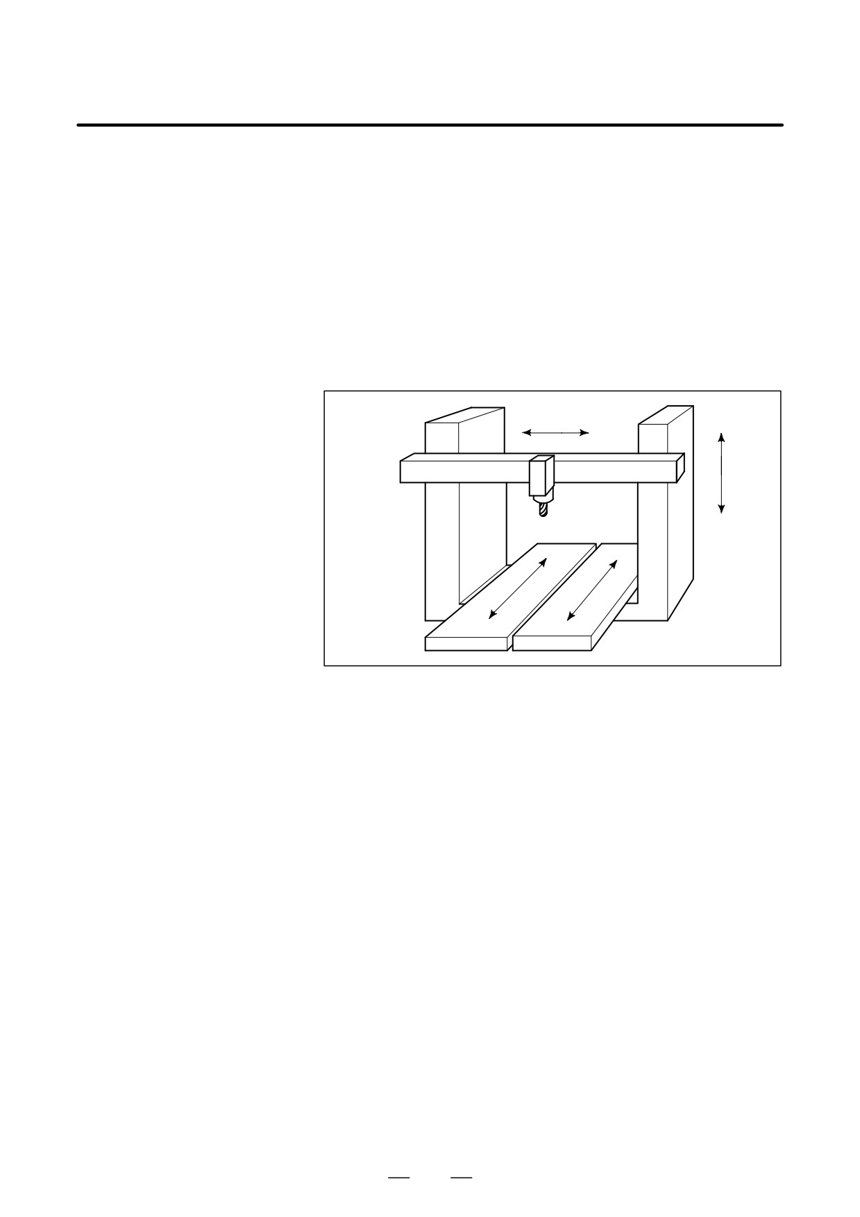
The following operating modes are applicable to machines having two
tables driven independently by separate control axes. The following
example is of a machine with two tables driven independently by the Y
axis and V axis. If the axis names and axis sets that are actually being used
differ from those in the example, substitute the actual names for those
below.
X
Z
Y
V
Fig. 20.1
Example of axis configuration of the machine operated
by simple synchronous control
Explanations
D Synchronous operation
This mode is used for, for example, machining large workpieces that
extend over two tables.
While operating one axis with a move command, it is possible to
synchronously move the other axis. In the synchronous mode, the axis
to which the move command applies is called the master axis, and the axis
that moves synchronously with the master axis is called the slave axis.
In this example, it is assumed that Y axis is the master axis and V axis is
the slave axis. Here, the Y axis and the V axis move synchronously in
accordance with program command Yyyyy issued to the Y axis (master
axis).
Synchronous operation is possible during automatic operation, jog feed,
manual handle feed using the manual pulse generator, and incremental
feed, but is not possible during manual reference position return.
404
B-64124EN/01
PROGRAMMING
20. AXIS CONTROL FUNCTIONS
D Normal operation
This operating mode is used for machining different workpieces on each
table. The operation is the same as in ordinary CNC control, where the
movement of the master axis and slave axis is controlled by the
independent axis address (Y and V). It is possible to issue the move
commands to both the master axis and slave axis in the same block.
(1) The Y axis moves normally according to program command Yyyyy
issued to the master axis.
(2) The V axis moves normally according to program command Vvvvv
issued to the slave axis.
(3) The Y axis and the V axis move simultaneously according to program
command YyyyyVvvvv.
Both automatic and manual operations are the same as in ordinary
CNC control.
D Switching between
For how to switch between the synchronous operation and normal
synchronous operation
operation modes, refer to the relevant manual published by the machine
and normal operation
tool builder.
D Automatic reference
When the automatic reference position return command (G28) and the
position return
2nd/3rd/4th reference position return command (G30) are issued during
synchronous operation, the V axis follows the same movement as the Y
axis returns to the reference position. After the return movement is
complete, the reference position return complete signal of the V axis goes
on when that of the Y axis goes on.
As a rule, commands G28 and G30 must be issued in the normal operating
mode.
D Automatic reference
When the automatic reference position return check command (G27) is
position return check
issued during synchronous operation, the V axis and Y axis move in
tandem. If both the Y axis and the V axis have reached their respective
reference positions after the movement is complete, the reference position
return complete signals go on. If either axis is not at the reference
position, an alarm is issued. As a rule, command G27 must be issued in
the normal operating mode.
D Specifying the slave axis
When a move command is issued to the slave axis during synchronous
operation, a P/S alarm (No. 213) is issued.
D Master axis and slave
The axis to be used as the master axis is set in parameter No. 8311.
axis
The slave axis is selected by an external signal.
D Displaying actual speed
Setting bit 7 (SMF) of parameter No. 3105 to 1 suppresses display of the
for master axis only
actual speed of the slave axes.
405
20. AXIS CONTROL FUNCTIONS
PROGRAMMING
B-64124EN/01
Limitations
D Setting a coordinate
In synchronous axis control, commands that require no axis motion, such
system
as the workpiece coordinate system setup command (G92) and the local
coordinate system setup command (G52), are set to the Y axis by program
command Yyyyy issued to the master axis.
D Externally-requested
For signals such as external deceleration, interlock, and machine lock,
deceleration, interlock,
only the signals issued to the master axis are valid in the synchronous
and machine lock
operating mode. Signals issued to other axes are ignored.
D Pitch error
Both the pitch error and backlash are compensated independently for the
compensation
master axis and the slave axis.
D Manual absolute
Turn on the manual absolute switch during synchronous operation. If it
is off, the slave axis may not move correctly.
D Synchronization error
The difference between the master axis and slave axis in servo positional
check using positional
deviation is always monitored. If the difference exceeds the parameter-
deviation
set limit, an P/S alarm (No. 213) is issued.
D Synchronization error
The difference between the master axis and slave axis in machine
check using machine
coordinates is always monitored. If the difference exceeds the parameter-
coordinates
set limit, an servo alarm (No. 407) is issued.
D Synchronization
When the power is turned on, compensation pulses are output for the slave
axis to match the machine position of the master axis with the machine
position of the slave axis.
(This is enabled only when the absolute
position detection function is used.)
D Compensation for
Compensation for out-of-synchronism (where the difference between
out-of-synchronism
the master and slave axes in servo positional deviation is always
monitored and the servo motor for the slave axis is compensated to reduce
the difference) is not performed.
D Manual reference
When the machine is manually returned to the reference position during
position return
synchronous operation, both the master axis and the slave axis move
synchronously until the acceleration movement is complete. However,
grid detection thereafter is carried out independently.
406
B-64124EN/01
PROGRAMMING
20. AXIS CONTROL FUNCTIONS
The roll-over function prevents coordinates for the rotation axis from
20.2
overflowing. The roll-over function is enabled by setting bit 0 of
ROTARY AXIS
parameter ROAx 1008 to 1.
ROLL-OVER
Explanations
For an incremental command, the tool moves the angle specified in the
command. For an absolute command, the coordinates after the tool has
moved are values set in parameter No. 1260, and rounded by the angle
corresponding to one rotation. The tool moves in the direction in which
the final coordinates are closest when bit 1 of parameter RABx No. 1008
is set to 0. Displayed values for relative coordinates are also rounded by
the angle corresponding to one rotation when bit 2 of parameter RRLx No.
1008 is set to 1.
Examples
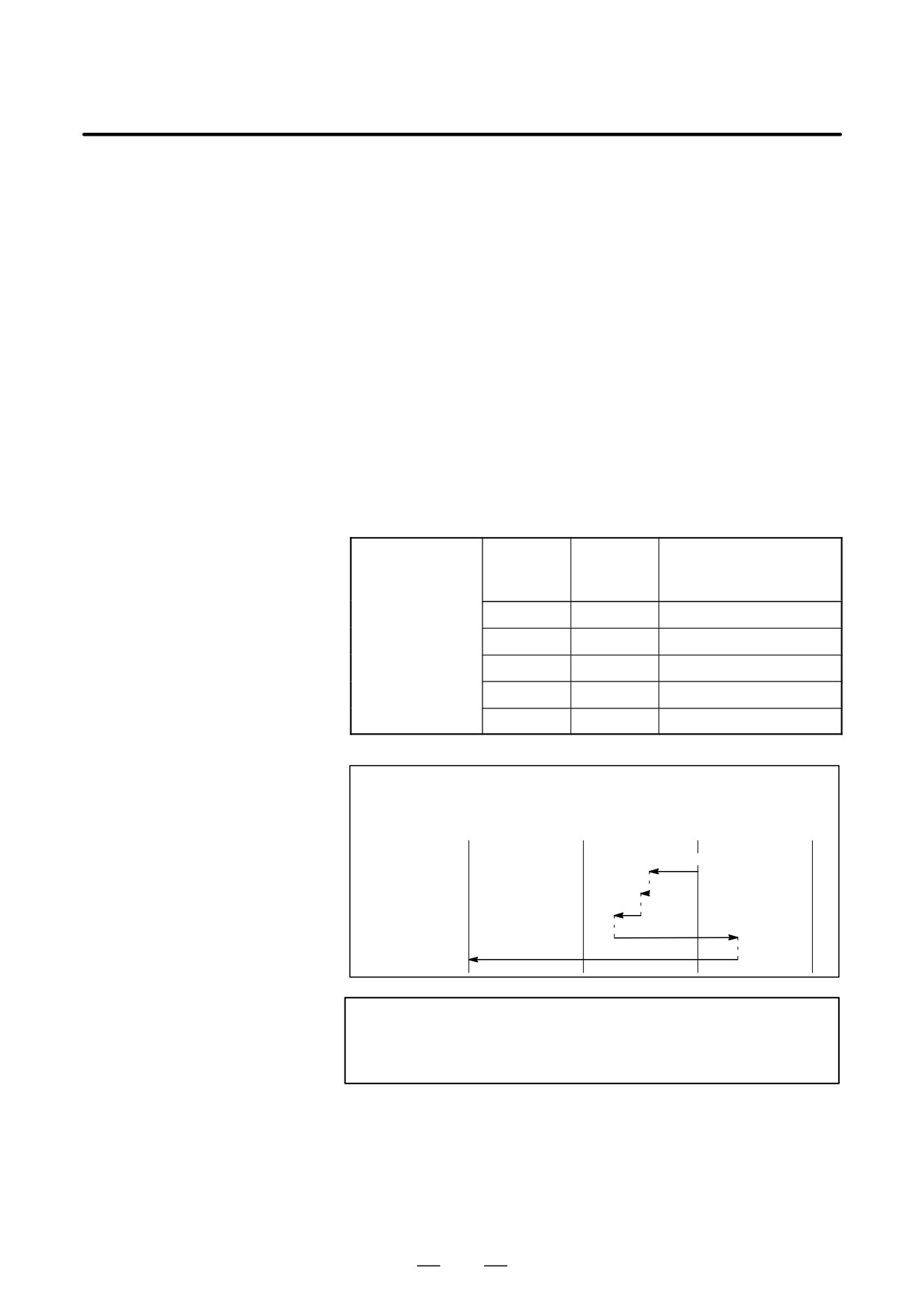
Assume that axis A is the rotating axis and that the amount of movement
per rotation is 360.000 (parameter No. 1260 = 360000). When the
following program is executed using the roll-over function of the rotating
axis, the axis moves as shown below.
Sequence
Actual
Absolute coordinate
G90 A0 ;
number
movement
value after movement
value
end
N1 G90 A-150.0 ;
N1
-150
210
N2 G90 A540.0 ;
N2
-30
180
N3 G90 A-620.0 ;
N3
-80
100
N4 G91 A380.0 ;
N4
+380
120
N5 G91 A-840.0 ;
N5
-840
0
Relative
-360°
-0°
360°
coordinate value-720°
Absolute
-0°
-0°
-0°
-0°
coordinate value
210°(Absolute)
N1
180°
N2
100°
N3
120°
N4
N5
NOTE
This function cannot be used together with the indexing
function of the index table.
407
20. AXIS CONTROL FUNCTIONS
PROGRAMMING
B-64124EN/01
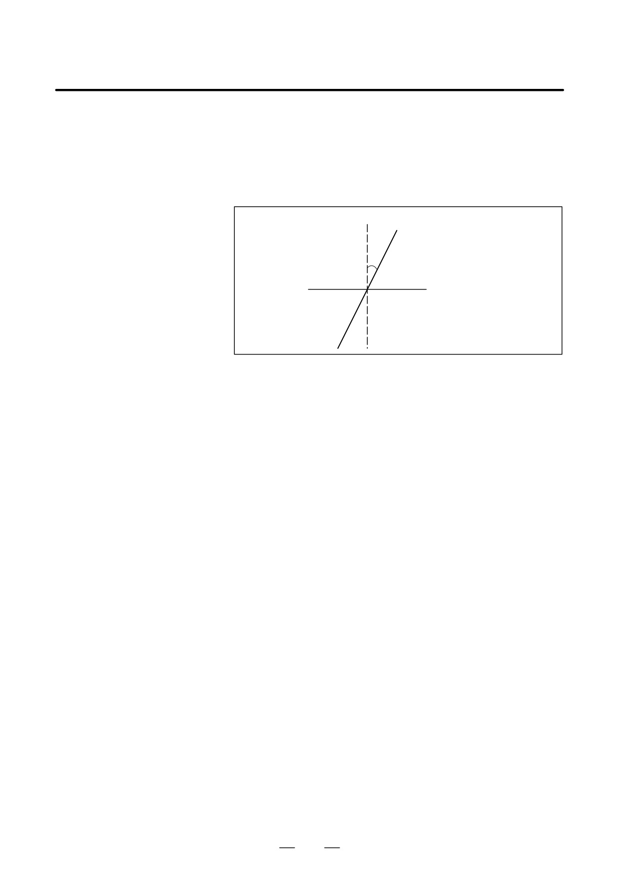
When the angular axis makes an angle other than
90° with the
20.3
perpendicular axis, the angular axis control function controls the distance
ANGULAR AXIS
traveled along each axis according to the inclination angle. A program,
CONTROL
when created, assumes that the angular axis and perpendicular axis
intersect at right angles. However, the actual distance traveled is
controlled according to an inclination angle.
+Y
Program coordinate system
+Y Coordinate system actually used
(Angular axis)
θ
+Z (Perpendicular axis)
θ : Inclination angle
Explanations
When the angular axis is the Y-axis and the perpendicular axis is the
Z-axis, the amount of travel along each axis is controlled according to the
formulas shown below.
The distance traveled along the Y-axis is determined by the following
formula:
Ya=Yp/cosθ
The distance traveled along the Z-axis is corrected by the inclination of
the Y-axis, and is determined by the following formula:
Za=Zp-Yp*tanθ
The speed component along the Y-axis is determined by the following
formula:
Fa=Fp/cosθ
Ya, Za, Fa : Actual distance and speed
Yp, Zp, Fp : Programmed distance and speed
D Method of use
The angular and perpendicular axes for which angular axis control is to
be applied must be specified beforehand, using parameters (No. 8211 and
8212).
Parameter AAC (No. 8200#0) enables or disables the inclined axis
control function. If the function is enabled, the distance traveled along
each axis is controlled according to an inclination angle parameter (No.
8210).
Parameter AZR (No. 8200#2) enables angular axis manual reference
point return only with a distance along the angular axis.
D Invalidity of normal axis
By setting the normal axis/angular axis control invalid signal NOZAGC
to 1, slanted axis control only for the angular axis can be available.
In this time the angular axis are converted to those along the slanted
coordinate system without affecting commands to normal axis.
D Absolute and relative
An absolute and a relative position are indicated in the programmed
position display
Cartesian coordinate system.
408
B-64124EN/01
PROGRAMMING
20. AXIS CONTROL FUNCTIONS
D Machine position display
A machine position indication is provided in the machine coordinate
system where an actual movement is taking place according to an
inclination angle. However, when inch/metric conversion is performed,
a position is indicated which incorporates inch/metric conversion applied
to the results of inclination angle operation.
WARNING
1
After angular axis control parameter setting, be sure to
perform manual reference position return operation.
2
If once manual reference position return has been
performed along the angular axis, also perform manual
reference position return along the perpendicular axis.
P/S alarm No.090 is issued when an attempt is made to
manually return to the reference position along the
perpendicular axis although the angular axis is not on the
reference point.
3
Once the tool has been moved along the angular axis when
perpendicular/angular axis control disable signal NOZAGC
has been set to 1, manual reference position return must be
performed.
4
Before attempting to manually move the tool along the
angular and perpendicular axes simultaneously, set
perpendicular/angular axis control disable signal NOZAGC
to 1.
NOTE
1
If an inclination angle close to 0° or ±90° is set, an error can
occur. (A range from ±20° to ±90° should be used.)
2
Before a perpendicular axis reference position return check
(G27) can be made, angular axis reference position return
operation must be completed.
409
20. AXIS CONTROL FUNCTIONS
PROGRAMMING
B-64124EN/01
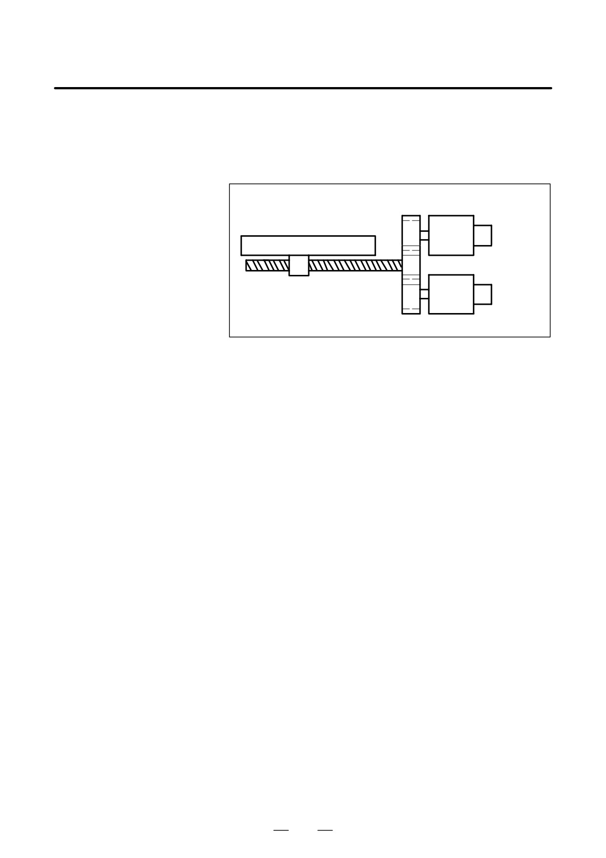
When enough torque for driving a large table cannot be produced by only
20.4
one motor, two motors can be used for movement along a single axis.
TANDEM CONTROL
Positioning is performed by the main motor only. The submotor is used
only to produce torque. With this tandem control function, the torque
produced can be doubled.
Main motor
Table
Ball screw
Submotor
Fig. 20.4 Example of operation
In general, the NC regards tandem control as being performed for one
axis. However, for servo parameter management and servo alarm
monitoring, tandem control is regarded as being performed for two axes.
For details, refer to the relevant manual published by the machine tool
builder.
410
III. OPERATION
B-64124EN/01
OPERATION
1. GENERAL
GENERAL
1
413
1. GENERAL
OPERATION
B-64124EN/01
1.1
MANUAL
OPERATION
Explanations
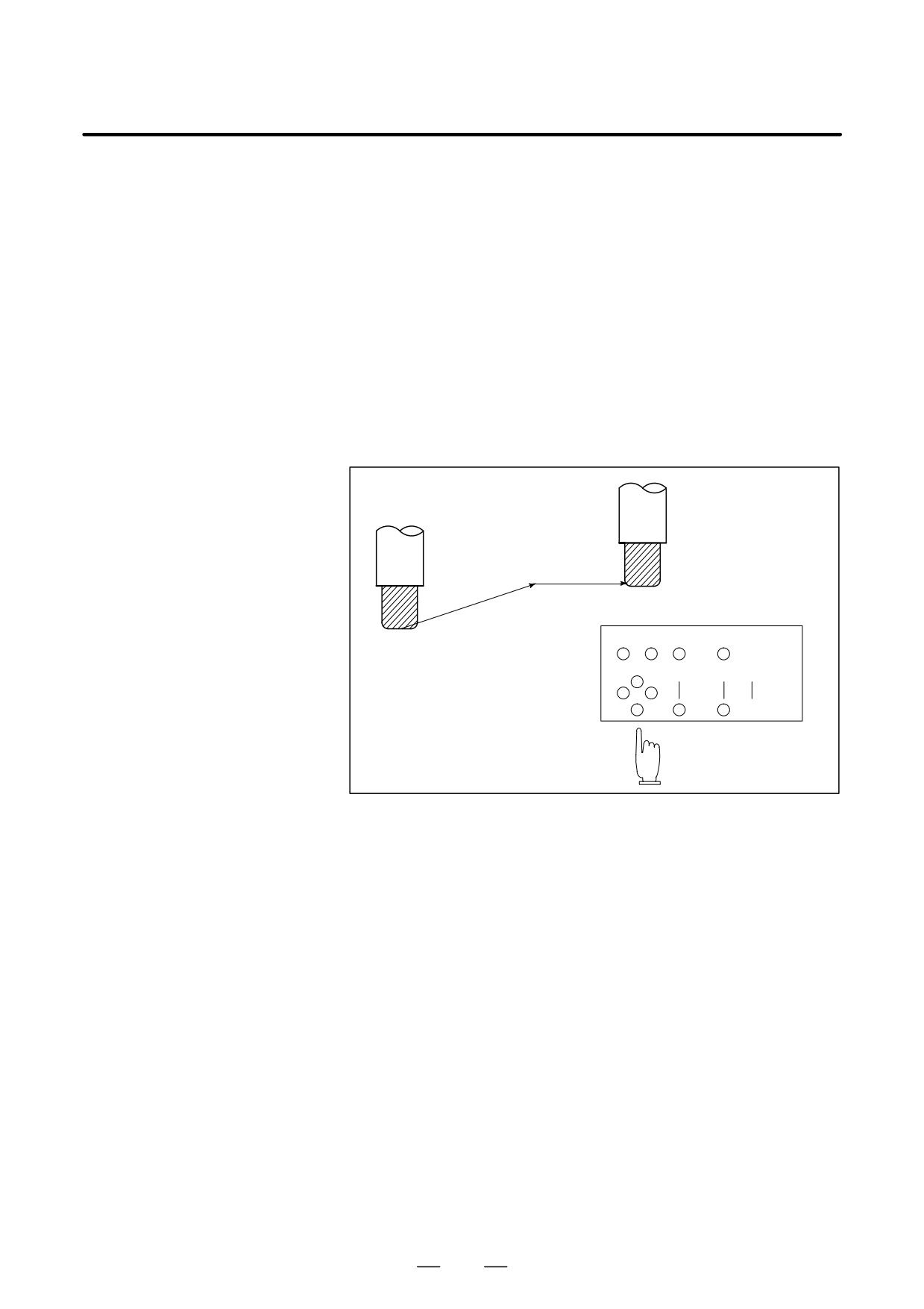
D Manual reference
The CNC machine tool has a position used to determine the machine
position return
position.
(See Section III-3.1)
This position is called the reference position, where the tool is replaced
or the coordinate are set. Ordinarily, after the power is turned on, the tool
is moved to the reference position.
Manual reference position return is to move the tool to the reference
position using switches and pushbuttons located on the operator’s panel.
Reference position
Tool
Machine operator’s panel
Fig. 1.1 (a) Manual reference position return
The tool can be moved to the reference position also with program
commands.
This operation is called automatic reference position return (See Section
II-6).
414
B-64124EN/01
OPERATION
1. GENERAL
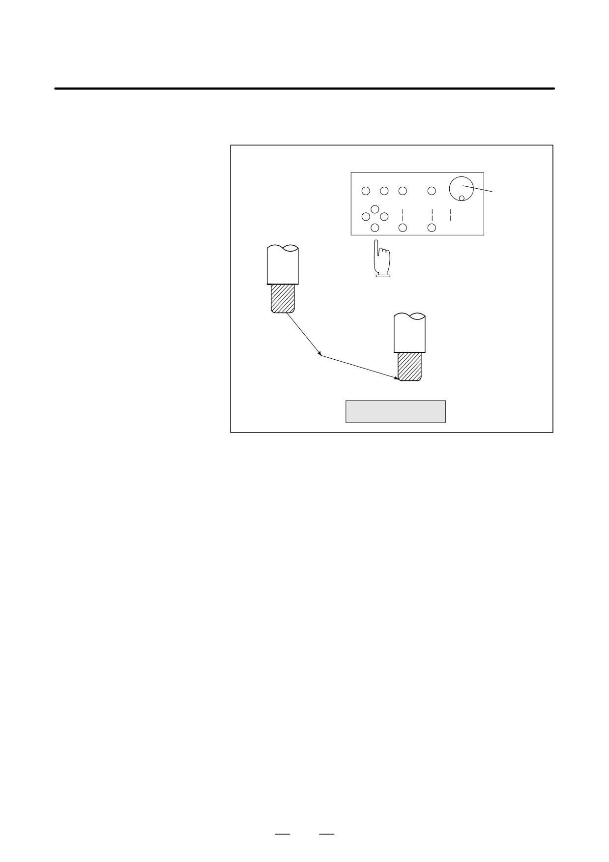
D The tool movement by
Using machine operator’s panel switches, pushbuttons, or the manual
manual operation
handle, the tool can be moved along each axis.
Machine operator’s panel
Manual
pulse
generator
Tool
Workpiece
Fig. 1.1 (b) The tool movement by manual operation
The tool can be moved in the following ways:
(i) Jog feed (See Section III-3.2)
The tool moves continuously while a pushbutton remains pressed.
(ii) Incremental feed (See Section III-3.3)
The tool moves by the predetermined distance each time a button is
pressed.
(iii) Manual handle feed (See Section III-3.4)
By rotating the manual handle,the tool moves by the distance
corresponding to the degree of handle rotation.
415
1. GENERAL
OPERATION
B-64124EN/01
1.2
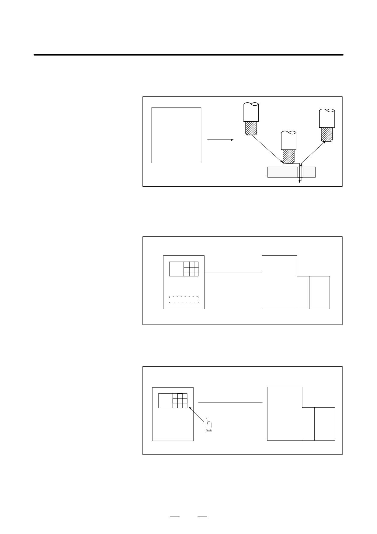
Automatic operation is to operate the machine according to the created
program. It includes memory, MDI and DNC operations. (See Section
TOOL MOVEMENT
III-4).
BY PROGRAMMING-
Program
AUTOMATIC
01000
;
OPERATION
M_S_T
;
Tool
G92_X_ ;
G00...
;
G01
;
Fig. 1.2 (a) Tool movement by programming
Explanations
D Memory operation
After the program is once registered in memory of CNC, the machine can
be run according to the program instructions. This operation is called
memory operation.
CNC
Machine
Memory
Fig. 1.2 (b) Memory operation
D MDI operation
After the program is entered, as an command group, from the MDI
keyboard, the machine can be run according to the program. This
operation is called MDI operation.
CNC MDI keyboard
Machine
Manual program
input
Fig. 1.2 (c) MDI operation
D DNC operation
In this mode of operation, the program is not registered in the CNC
memory. It is read from the external input/output devices instead. This
is called DNC operation. This mode is useful when the program is too
large to fit the CNC memory.
416
B-64124EN/01
OPERATION
1. GENERAL
1.3
AUTOMATIC
OPERATION
Explanations
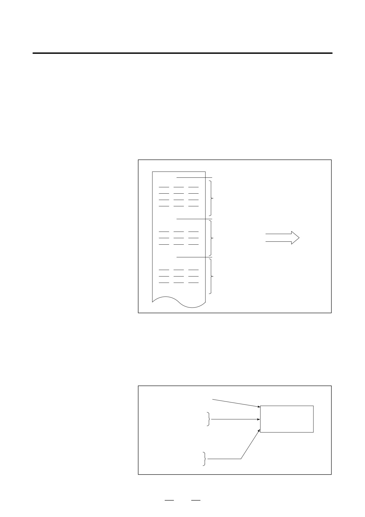
D Program selection
Select the program used for the workpiece. Ordinarily, one program is
prepared for one workpiece. If two or more programs are in memory,
select the program to be used, by searching the program number (Section
III-9.3).
In memory or on a tape
O1001
Program number
G92
------
Work-1 program
M30
O1002
Program number
Program number
G92
------
search
Work-2 program
Automatic
operation
M30
O1003
Program number
G92
------
Work-3 program
M30
Fig. 1.3 (a) Program selection for automatic operation
D Start and stop
Pressing the cycle start pushbutton causes automatic operation to start.
(See Section III-4)
By pressing the feed hold or reset pushbutton, automatic operation pauses
or stops. By specifying the program stop or program termination
command in the program, the running will stop during automatic
operation. When one process machining is completed, automatic
operation stops.
Start
Cycle start
Stop
Feed hold
Automatic operation
Reset
Program stop Stop caused
Program end
by program
Fig. 1.3 (b) Start and stop for automatic operation
417
1. GENERAL
OPERATION
B-64124EN/01
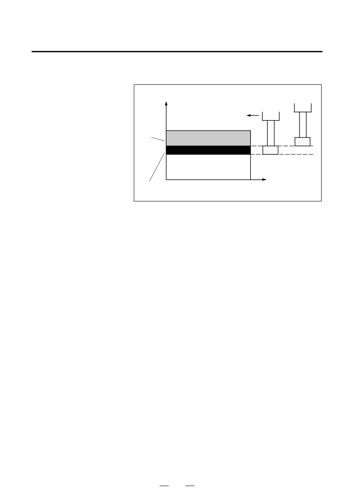
D Handle interruption
While automatic operation is being executed, tool movement can overlap
(See Section III-4.7)
automatic operation by rotating the manual handle.
Tool position during
Z
automatic operation
Tool position after
handle interruption
Programmed
depth of cut
X
Depth of cut by
handle interruption
Fig. 1.3 (c) Handle Interruption for automatic operation
418
B-64124EN/01
OPERATION
1. GENERAL
1.4
Before machining is started, the automatic running check can be
executed. It checks whether the created program can operate the machine
TESTING A
as desired. This check can be accomplished by running the machine
PROGRAM
actually or viewing the position display change (without running the
machine) (See Section III-5).
1.4.1
Check by Running the
Machine
Explanations
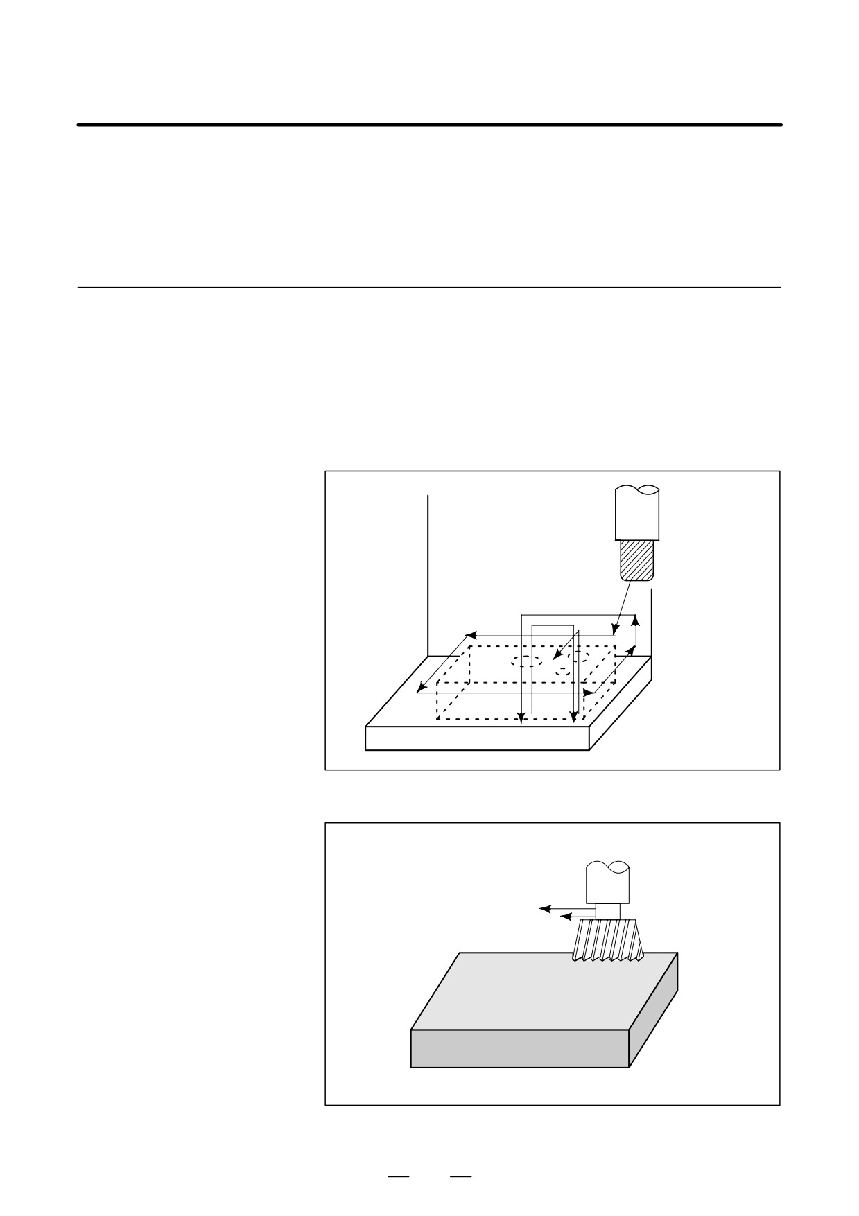
D Dry run
Remove the workpiece, check only movement of the tool. Select the tool
(See Section III-5.4)
movement rate using the dial on the operator’s panel.
Tool
Table
Fig. 1.4.1 (a) Dry run
D Feedrate override
Check the program by changing the feedrate specified in the program.
(See Section III-5.2)
Feed rate specified by program :
100 mm/min.
Tool
Feed rate after feed rate override (20%) :
20 mm/min.
Workpiece
Fig. 1.4.1 (b) Feedrate override
419
1. GENERAL
OPERATION
B-64124EN/01
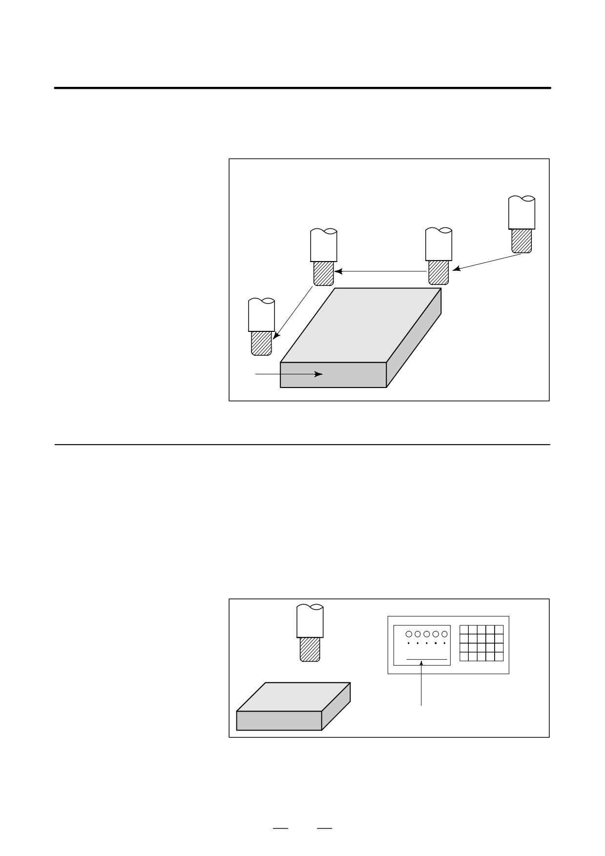
D Single block
When the cycle start pushbutton is pressed, the tool executes one
(See Section III-5.5)
operation then stops. By pressing the cycle start again, the tool executes
the next operation then stops. The program is checked in this manner.
Cycle start
Cycle start
Cycle start
Tool
Stop
Stop
Cycle start
Workpiece
Stop
Fig. 1.4.1 (c) Single block
1.4.2
How to View the
Position Display
Change without
Running the Machine
Explanations
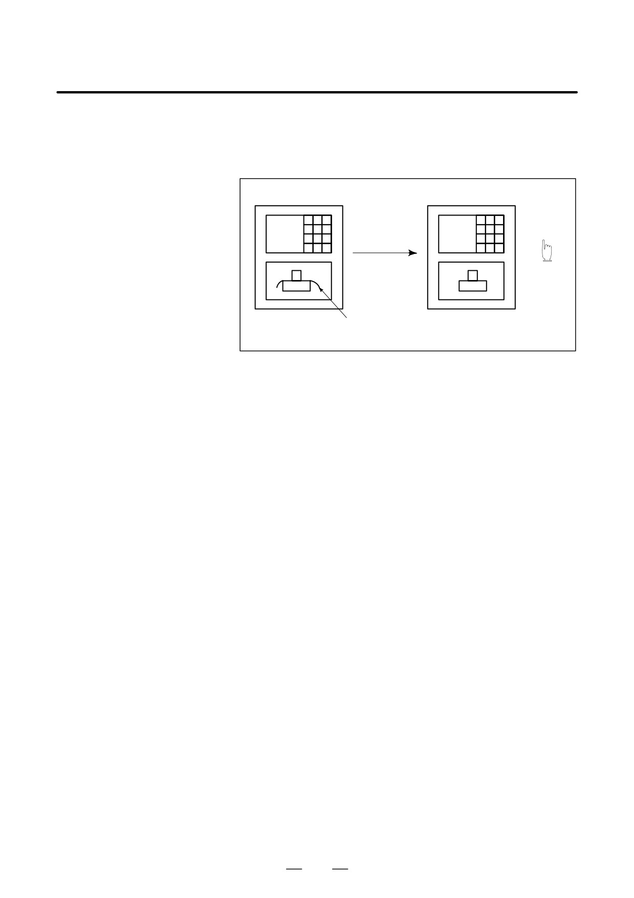
D Machine lock
(See Sections III-5.1)
MDI
X
Tool
Y
Z
Workpiece
The tool remains stopped, and only the
positional displays of the axes change.
Fig. 1.4.2 Machine lock
D Auxiliary function lock
When automatic running is placed into the auxiliary function lock mode
(See Section III-5.1)
during the machine lock mode, all auxiliary functions (spindle rotation,
tool replacement, coolant on/off, etc.) are disabled.
420
B-64124EN/01
OPERATION
1. GENERAL
1.5
After a created program is once registered in memory, it can be corrected
or modified from the MDI panel (See Section III-9).
EDITING A PART
This operation can be executed using the part program storage/edit
PROGRAM
function.
Program registration
Program correction or modification
MDI
Tape reader
CNC
CNC
CNC tape (program)
Fig. 1.5 Part program editing
421
1. GENERAL
OPERATION
B-64124EN/01
1.6
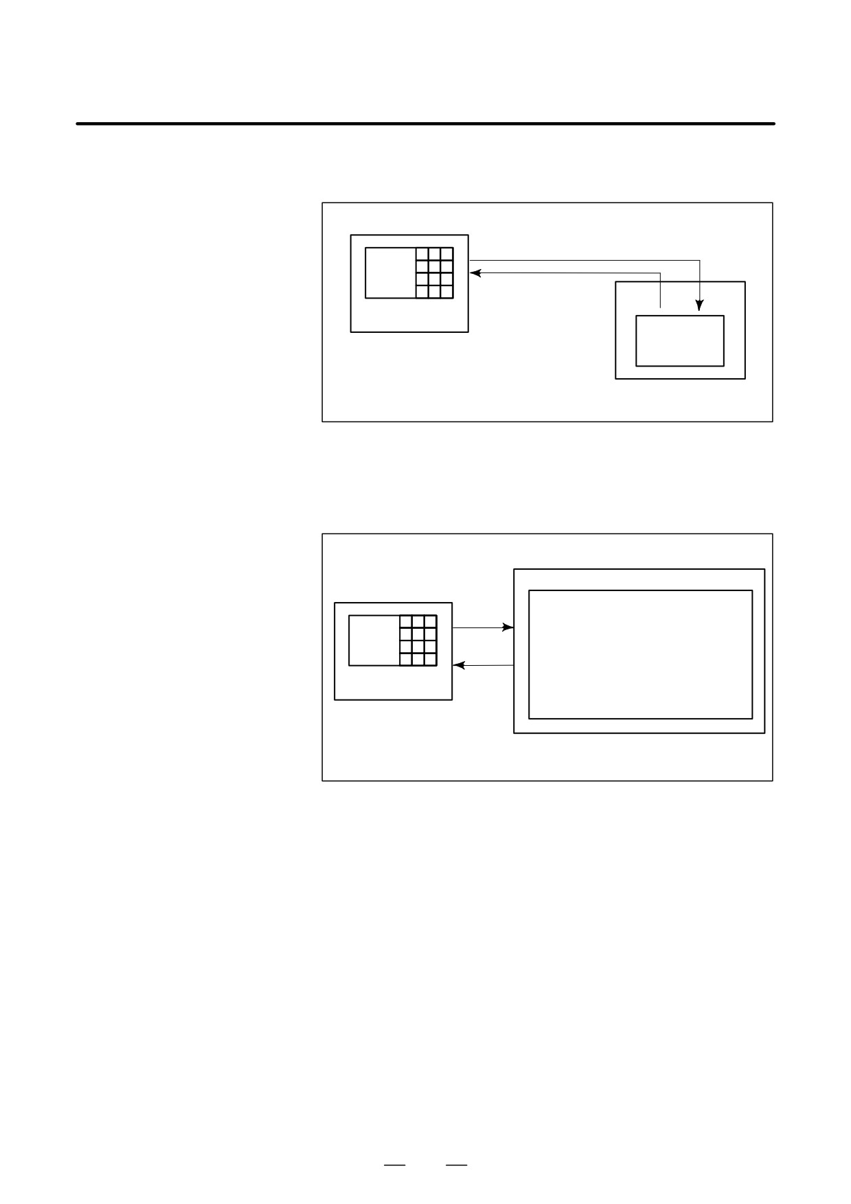
The operator can display or change a value stored in CNC internal
memory by key operation on the MDI screen (See III-11).
DISPLAYING AND
SETTING DATA
Data setting
Data display
Screen Keys
MDI
CNC memory
Fig. 1.6 (a) Displaying and setting data
Explanations
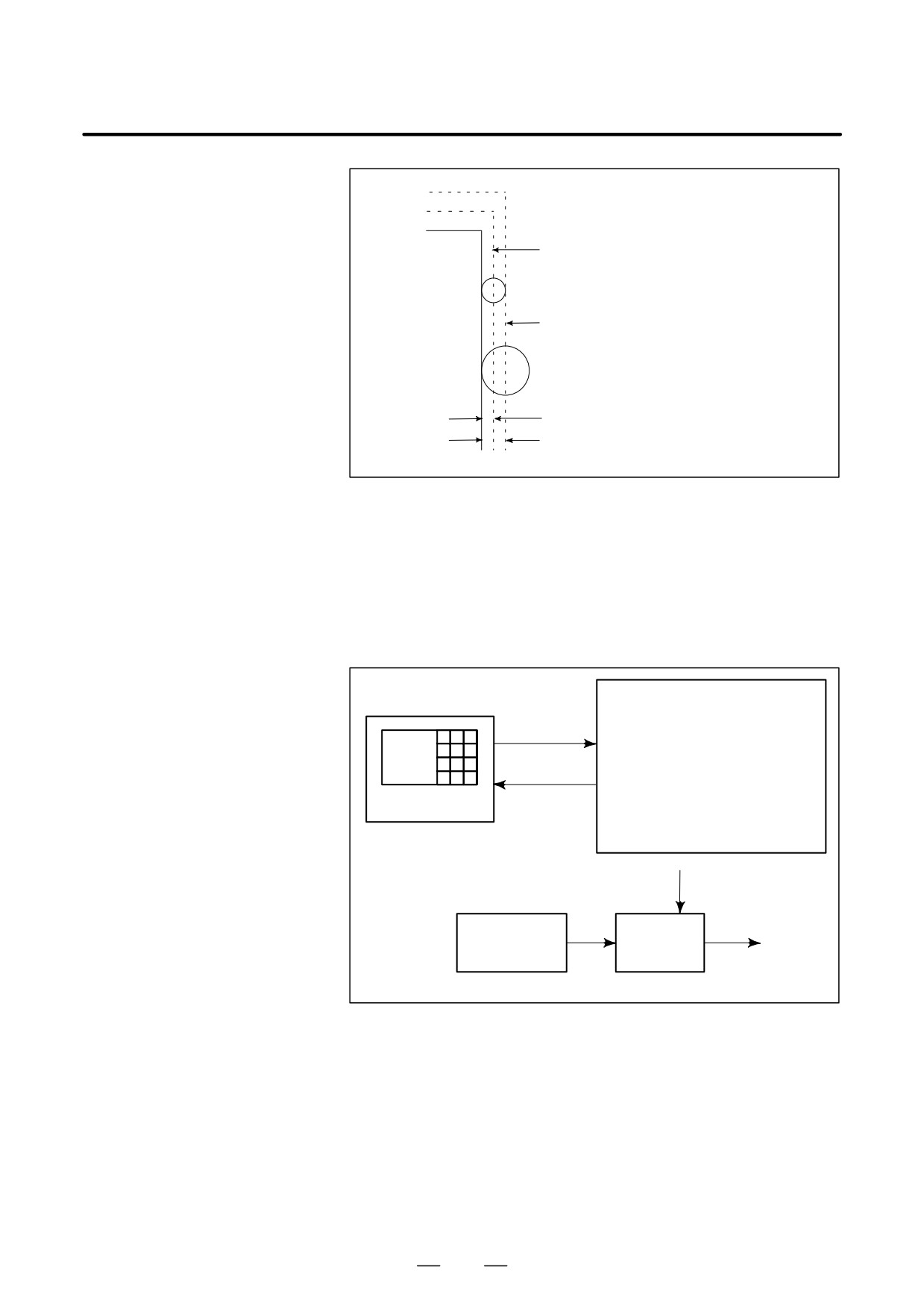
D Offset value
Geometry
Wear com-
compensation
pensation
Setting
Tool compensation
number1
12.3
25.0
Tool compensation
number2
20.0
40.0
Tool compensation
number3
⋅ ⋅ ⋅
⋅ ⋅ ⋅
Screen Keys
Display
⋅ ⋅ ⋅ ⋅ ⋅ ⋅ ⋅ ⋅ ⋅ ⋅ ⋅ ⋅ ⋅ ⋅ ⋅ ⋅
⋅ ⋅ ⋅
⋅ ⋅ ⋅
⋅ ⋅ ⋅ ⋅ ⋅ ⋅ ⋅ ⋅ ⋅ ⋅ ⋅ ⋅ ⋅ ⋅ ⋅ ⋅
⋅ ⋅ ⋅
⋅ ⋅ ⋅
MDI
CNC memory
Fig.1.6 (b) Displaying and setting offset values
The tool has the tool dimension (length, diameter). When a workpiece is
machined, the tool movement value depends on the tool dimensions.
By setting tool dimension data in CNC memory beforehand,
automatically generates tool routes that permit any tool to cut the
workpiece specified by the program. Tool dimension data is called the
offset value
(See Section III-11.4.1).
422
B-64124EN/01
OPERATION
1. GENERAL
1st tool path
Machined
shape
2nd tool path
Offset value of the 1st tool
Offset value of the 2nd tool
Fig. 1.6 (c) Offset value
D Displaying and setting
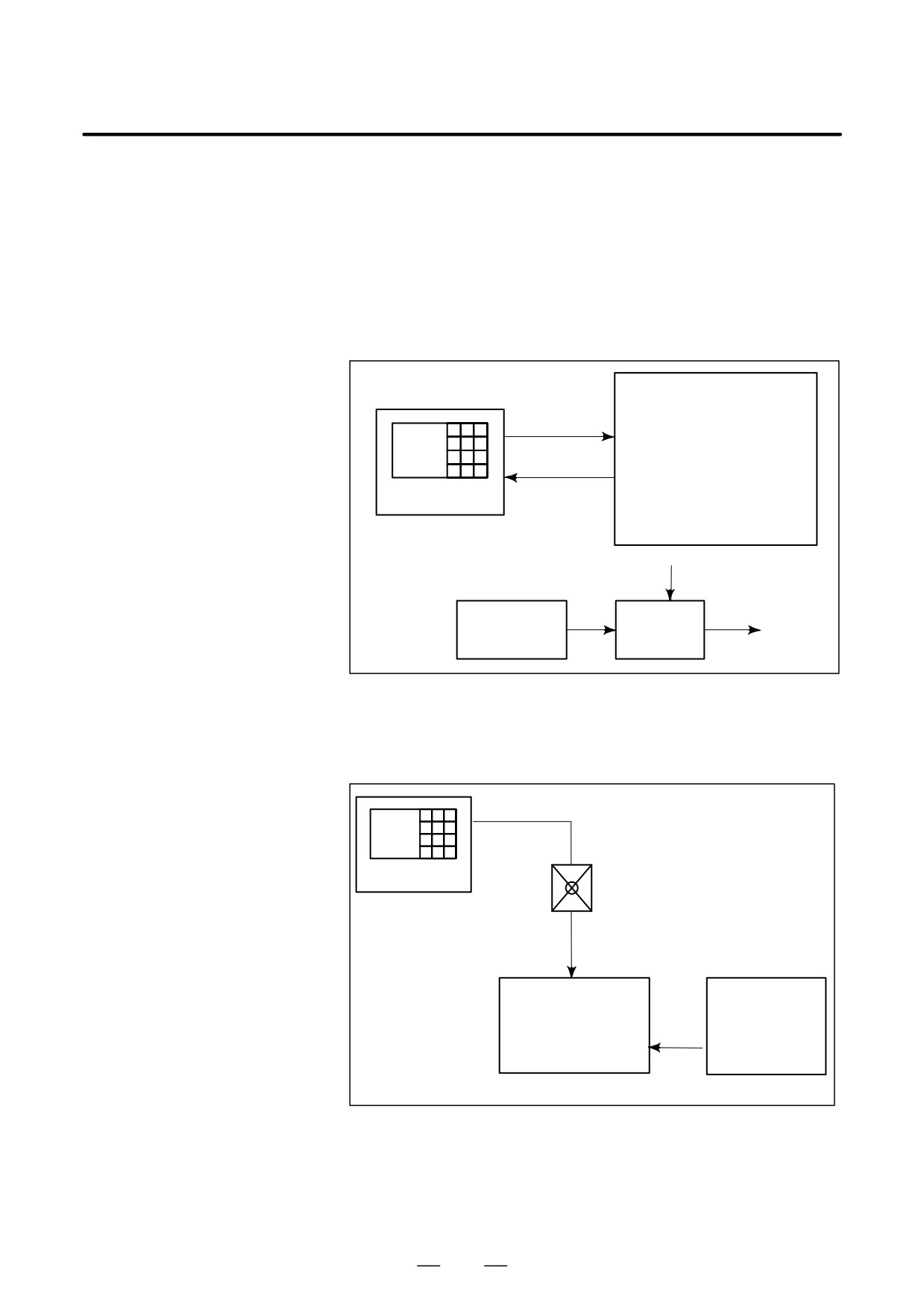
Apart from parameters, there is data that is set by the operator in
operator’s setting data
operation. This data causes machine characteristics to change.
For example, the following data can be set:
S Inch/Metric switching
S Selection of I/O devices
S Mirror image cutting on/off
The above data is called setting data (See Section III-11.4.3).
Setting data
Setting
⋅Inch/Metric switching
⋅Selection of I/O device
⋅Mirror image ON/OFF setting
⋅
Screen Keys
Displaying
⋅
⋅
CNC Memory
Operational
characteristics
Program
Automatic
operation
Movement of
the machine
Fig. 1.6 (d) Displaying and setting operator’s setting data
423
1. GENERAL
OPERATION
B-64124EN/01
D Displaying and setting
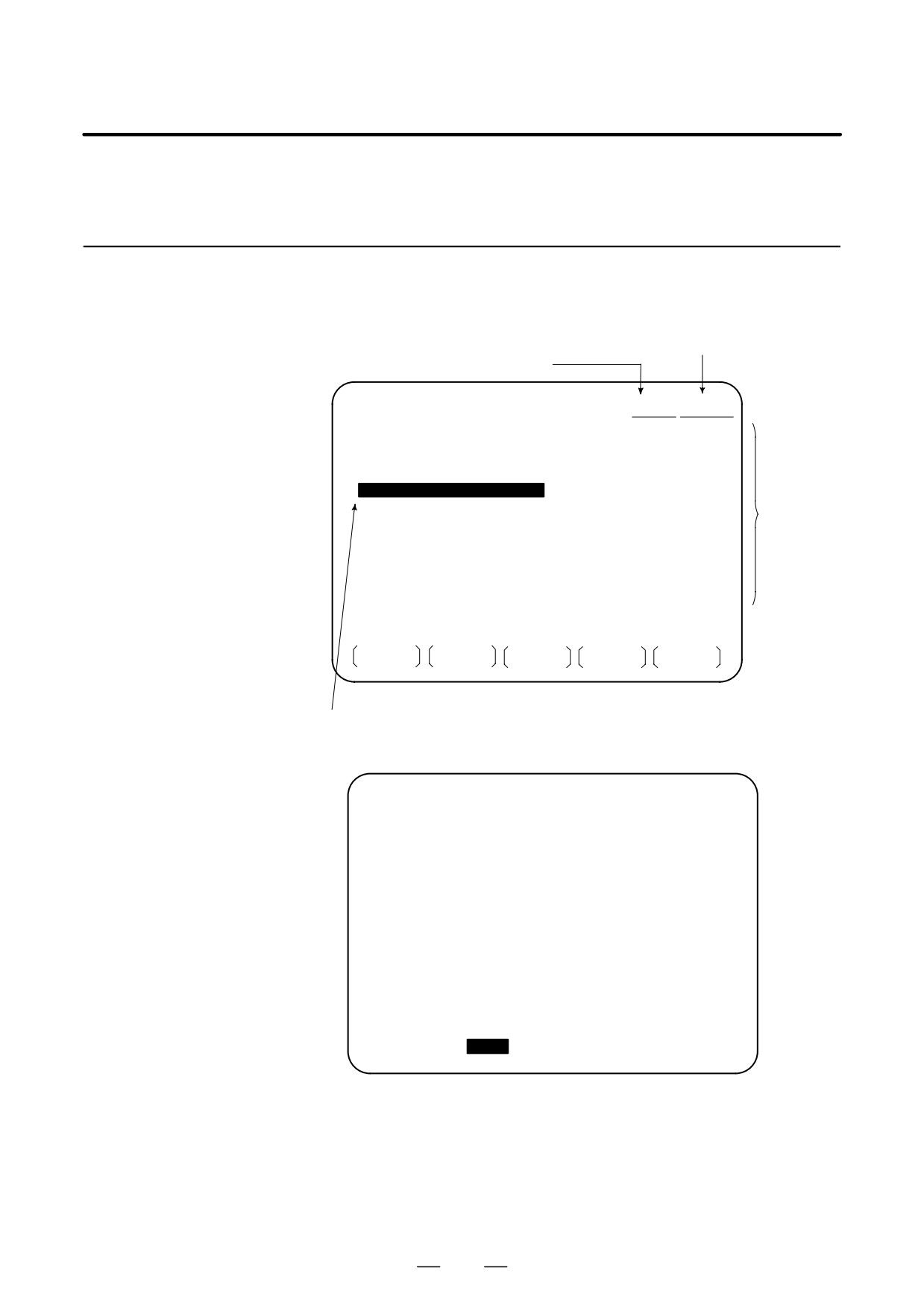
The CNC functions have versatility in order to take action in
parameters
characteristics of various machines.
For example, CNC can specify the following:
S Rapid traverse rate of each axis
S Whether increment system is based on metric system or inch system.
S How to set command multiply/detect multiply (CMR/DMR)
Data to make the above specification is called parameters (See Section
III-11.5.1).
Parameters differ depending on machine tool.
Parameter
Rapid traverse rate
Setting
Position control
Reference position return
Backlash compensation data
Pitch error compensation
Screen Keys
Display
data
⋅
⋅
MDI
⋅
CNC memory
Operational
characteristics
Movement
Program
Automatic
of the
operation
machine
Fig. 1.6 (e) Displaying and setting parameters
D Data protection key
A key called the data protection key can be defined. It is used to prevent
part programs, offset values, parameters, and setting data from being
registered, modified, or deleted erroneously
(See Section III-11).
Data Setting
Screen Keys
Protection Key
MDI
Registration / modification inhibition
Machine operator’s
panel
Program
Offset value
Data protection
Signal
Parameters
key
Setting data
CNC memory
Fig. 1.6 (f) Data protection key
424
B-64124EN/01
OPERATION
1. GENERAL
1.7
DISPLAY
1.7.1
The contents of the currently active program are displayed. In addition,
the programs scheduled next and the program list are displayed.
Program Display
(See Section III-11.2.1)
Active sequence number
Active program number
PROGRAM
1100
00005
N1
G90 G17 G00 G41 D07 X250.0 Y550.0 ;
N2
G01 Y900.0 F150 ;
N3
X450.0 ;
N4
G03 X500.0 Y1150.0 R650.0 ;
N5 G02 X900.0 R-250.0 ;
Program
N6
G03 X950.0 Y900.0 R650.0 ;
content
N7 G01 X1150.0 ;
N8
Y550.0 ;
N9
X700.0 Y650.0 ;
N10 X250.0 Y550.0 ;
N11 G00 G40 X0 Y0 ;
>_
MEM STOP * * *
* * *
13 : 18 : 14
PRGRM
CHECK
CURRNT
NEXT
(OPRT)
Currently executed program
The cursor indicates the currently executed location
PROGRAM DIRECTORY
O0001 N00010
PROGRAM (NUM.) MEMORY (CHAR.)
USED:
60
3321
FREE:
2
429
O0001
(MACRO-GCODE.MAIN)
O0002
(MACRO-GCODE.SUB1)
O0010
(TEST-PROGRAM.ARTHMETIC NO.1)
O0020
(TEST-PROGRAM.F10-MACRO)
O0040
(TEST-PROGRAM.OFFSET)
O0050
O0100
(INCH/MM CONVERT CHECK NO.1)
O0200
(MACRO-MCODE.MAIN)
> _
EDIT **** *** ***
16:05:59
[ PRGRM ]
[
DIR+
]
[
]
[
]
[
(OPRT) ]
425
1. GENERAL
OPERATION
B-64124EN/01
1.7.2
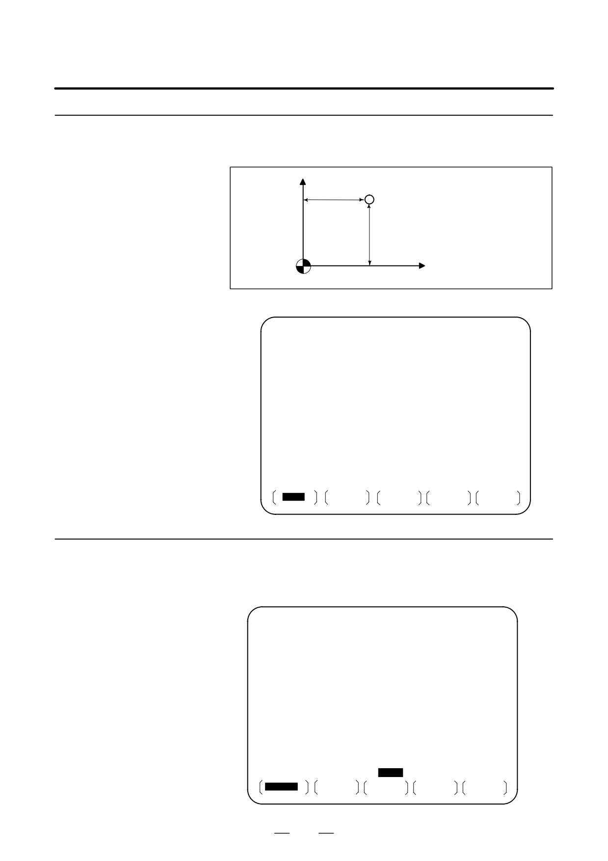
The current position of the tool is displayed with the coordinate values.
The distance from the current position to the target position can also be
Current Position
displayed. (See Section III-11.1.1 to 11.1.3)
Display
Y
x
y
X
Workpiece coordinate system
ACTUAL POSITION (ABSOLUTE)
O0003 N00003
X 150.000
Y 300.000
Z 100.000
PART COUNT 30
RUN TIME
0H41M CYCLE TIME 0H 0M22S
MEM
* * * *
* * *
* * *
19 : 47 : 45
ABS
REL
ALL
(OPRT)
1.7.3
When a trouble occurs during operation, alarm number and alarm
message are displayed on the screen. (See Section III-7.1)
Alarm Display
See APPENDIX G for the list of alarms and their meanings.
ALARM MESSAGE
O1000 N00003
010
IMPROPER G-CODE
>_
MEM STOP
* * *
* * *
ALM
19 : 55 : 22
ALARM
MSG
HISTRY
426
B-64124EN/01
OPERATION
1. GENERAL
1.7.4
Run time and number of parts are displayed on the screen. (See Section
lll-11.4.5)
Parts Count Display,
Run Time Display
ACTUAL POSITION (ABSOLUTE)
O0003 N00003
X 150.000
Y 300.000
Z 100.000
PART COUNT 18
RUN TIME
0H16M CYCLE TIME 0H 1M 0S
MEM STRT
FIN
* * * *
20 : 22 : 23
ABS
REL
ALL
(OPRT)
1.7.5
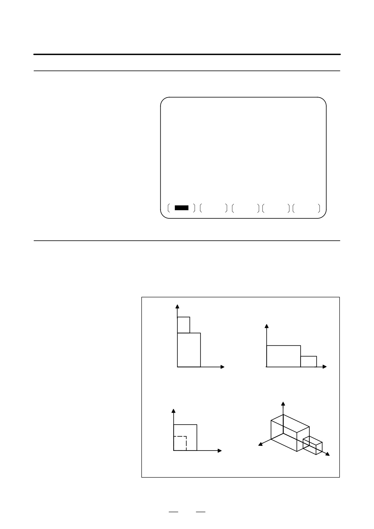
Programmed tool movement can be displayed on the following planes:
(See Section III-12)
Graphic Display
1) XY plane
2) YZ plane
3) XZ plane
4) Three dimensional display
(1)
Y
(2)
Z
X
Y
Display on the XY plane
Display on the YZ plane
(3)
Z
(4)
Z
X
X
Y
Display on the XZ plane
Three dimensional display (isometric)
Fig. 1.7.5 Graphic display
427
1. GENERAL
OPERATION
B-64124EN/01
1.8
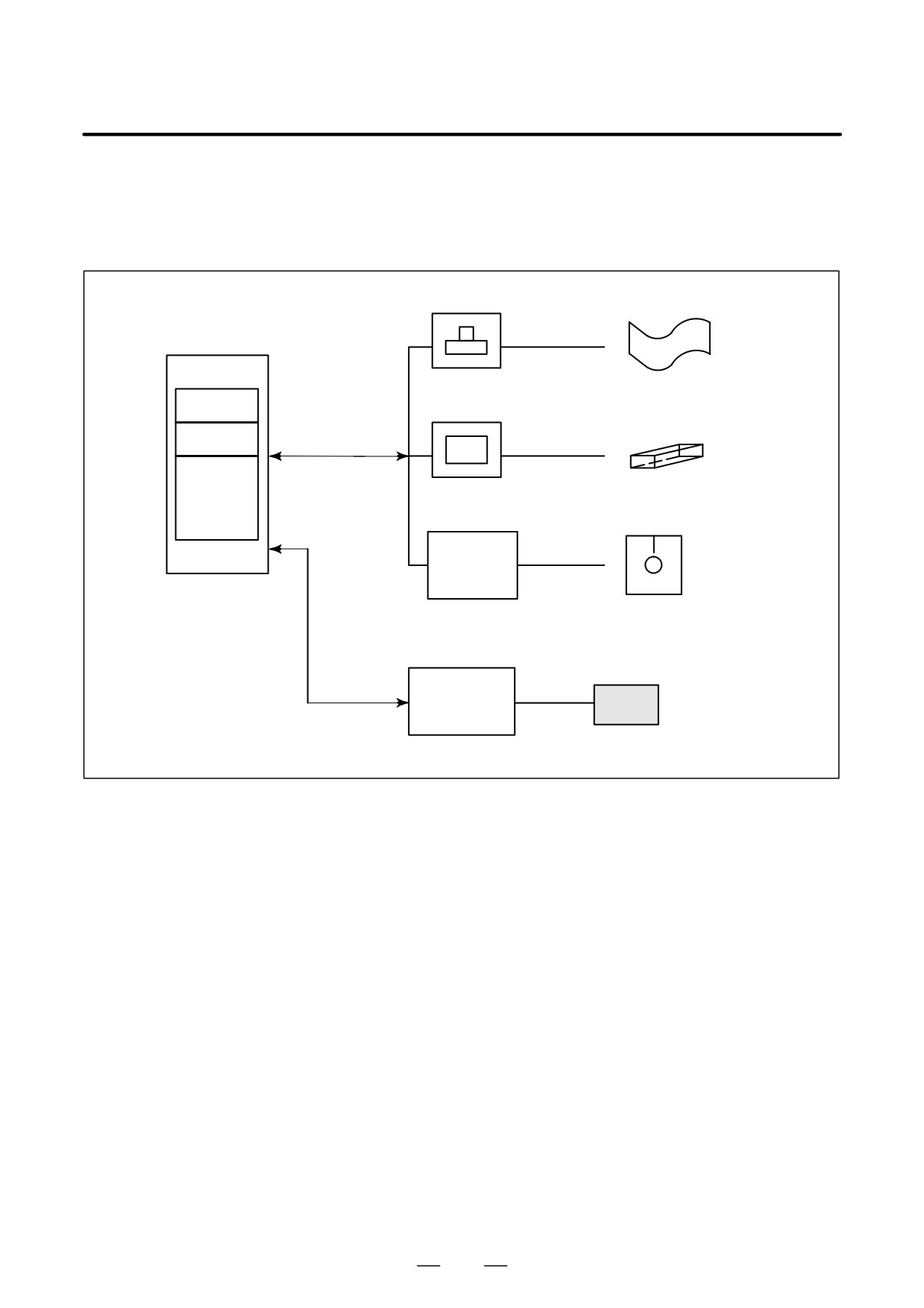
Programs, offset values, parameters, etc. input in CNC memory can be
output to paper tape, cassette, or a floppy disk for saving. After once
DATA INPUT /
output to a medium, the data can be input into CNC memory.
OUTPUT
Portable tape reader
FANUC PPR
Memory
Paper tape
Program
FANUC Floppy Cassette
Reader/puncher
FANUC Floppy
Offset
interface
cassette adaptor
Parameters
Floppy disk
SYSTEM P
CNC
Automatic programming system
Memory card
Memory card
adapter
(incorporated CNC)
Fig. 1.8 Data Output
428
B-64124EN/01
OPERATION
2. OPERATIONAL DEVICES
OPERATIONAL DEVICES
2
The available operational devices include the setting and display unit
attached to the CNC, the machine operator’s panel, and external
input/output devices such as a Handy File.
429
2. OPERATIONAL DEVICES
OPERATION
B-64124EN/01
2.1
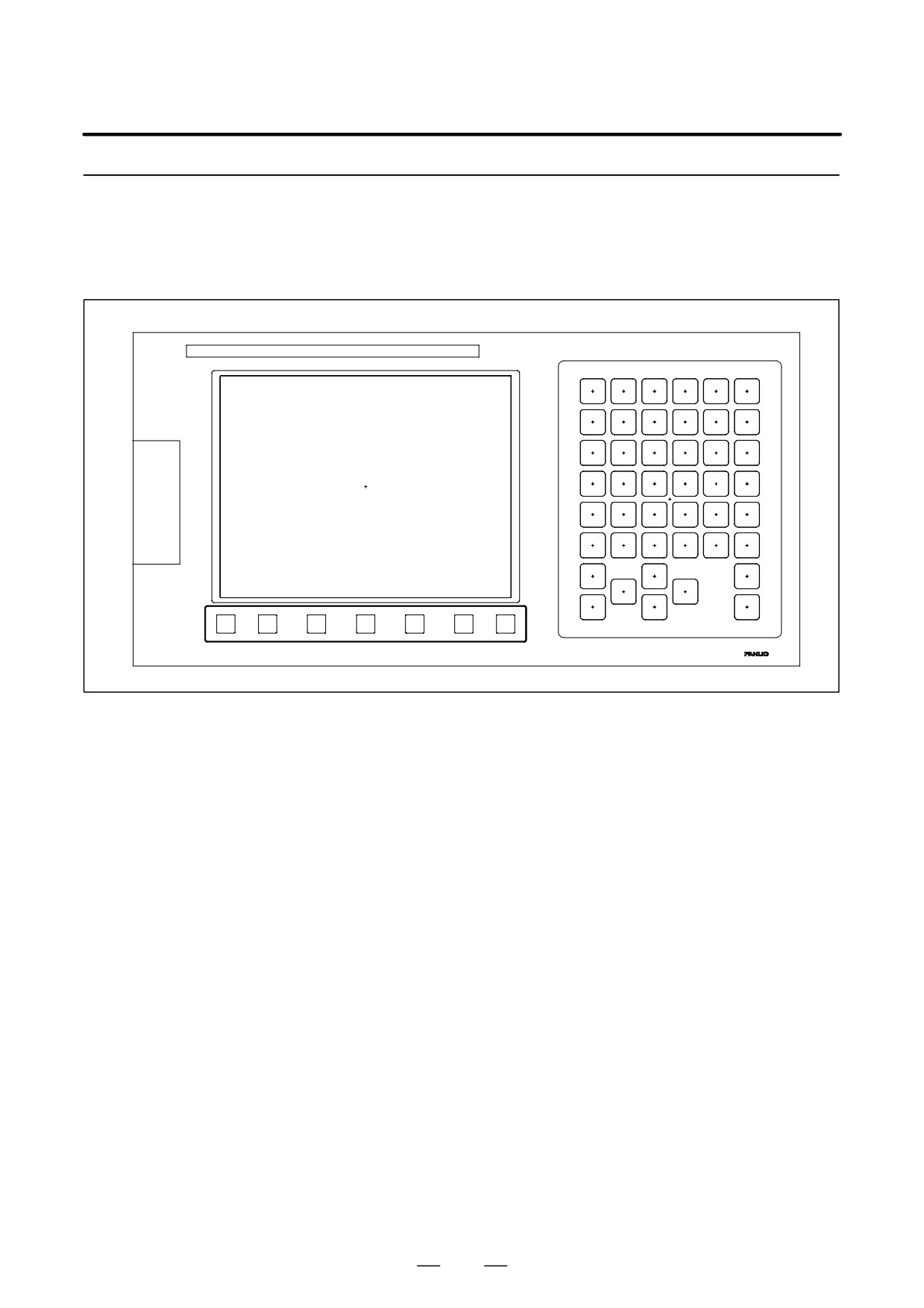
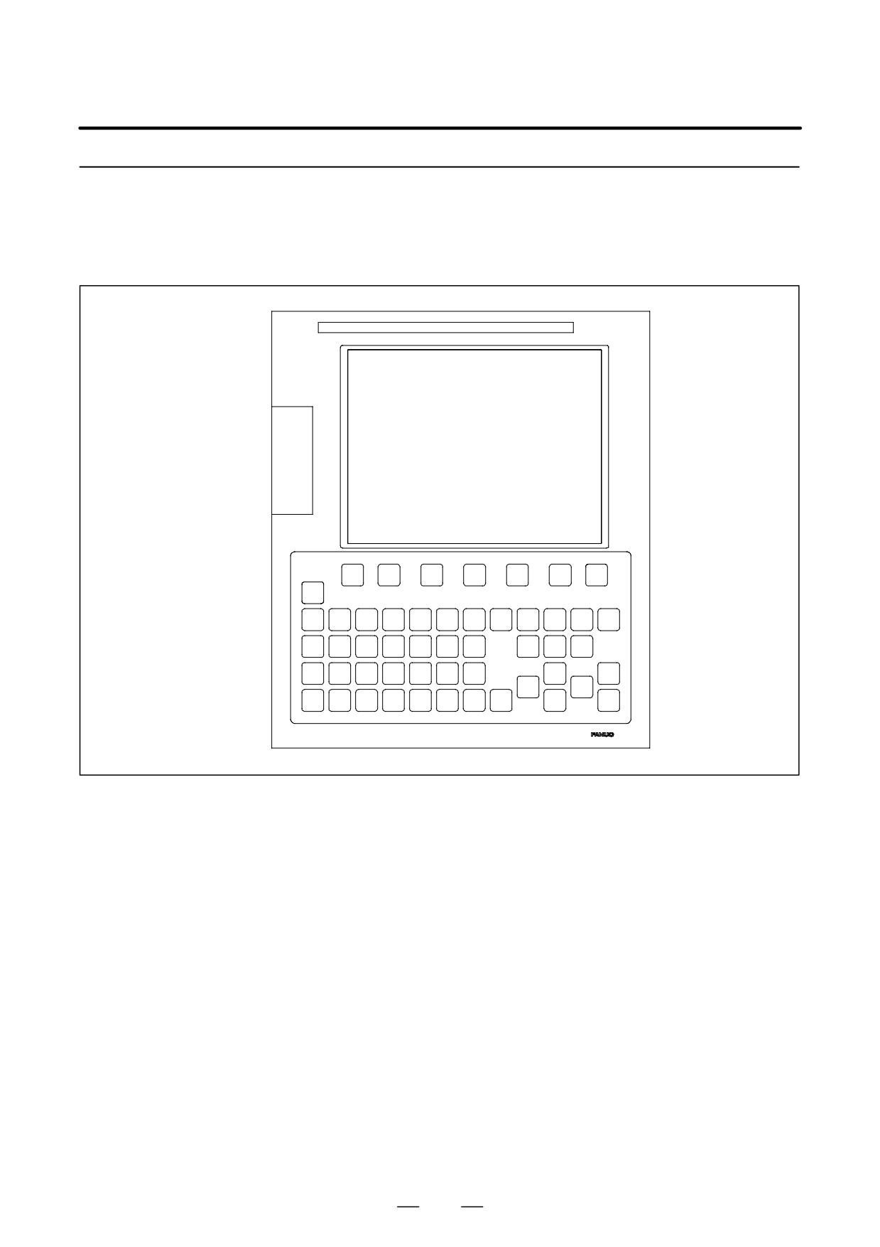
The setting and display units are shown in Subsections 2.1.1 to 2.1.4 of
Part III.
SETTING AND
DISPLAY UNITS
7.2″ monochrome / 8.4″ color LCD/MDI unit
(horizontal type)
III-2.1.1
7.2″ monochrome / 8.4″ color LCD/MDI unit
(vertical type)
III-2.1.2
Key location of MDI (horizontal type LCD/MDI unit) . . . III-2.1.3
Key location of MDI (vertical type LCD/MDI unit)
III-2.1.4
430
B-64124EN/01
OPERATION
2. OPERATIONAL DEVICES
2.1.1
7.2″ Monochrome/
8.4″ Color LCD/MDI
Unit (Horizontal Type)
431
2. OPERATIONAL DEVICES
OPERATION
B-64124EN/01
2.1.2
7.2″ Monochrome/
8.4″ Color LCD/MDI
Unit (Vertical Type)
432