FANUC MANUAL GUIDE i. OPERATOR’S MANUAL - page 33
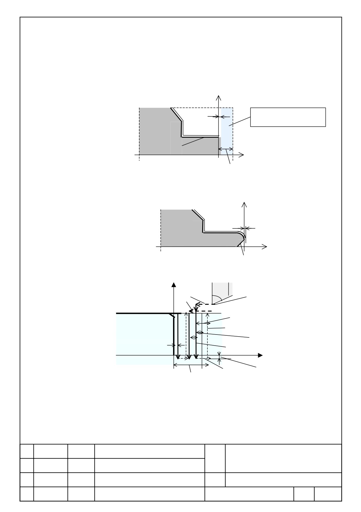
As the figure below, even though 1st figure part is started from a point X>0,
face part will be cut when face removal is set. However, face part is cut off
as below figure, even with these part figure is defined.
X
This face part is cut out
Finish Amount Z
even it is part figure.
1st Figure Part
Z
Face Removal
As upper description, when finish amount is set, finishing amount of face
part remain after completing outer facing rough.
X
Finish Amount
Z
1st Figure Part
Cut off the face part operates as followings.
+X
(a)
Start Point of Machining
(e)
●
(Xs, Zs)
X1
Escape Amount U
(d)
Cut Depth Q
Finish Amount W
(b)
X0
+Z
Z1
(c)
Nose Diameter+Clearance X
Z0
Face Removal I
(a) Tool is moved to “Z1-Q” beside Z axis
Then, move to [X1 + Clearance] beside X axis
(b) Tool is cut “X0 - Nose Diameter*2 - Clearance*2” beside X axis.
(c) Tool is returned to “Z1 + Clearance” beside Z axis by G00.
(d) Tool is returned to X1+ClearanceX*2 by G00.
(e) Tool is moved to “Z1-2*Q”, the point cut by amout Q from the last cut
position, beside Z axis by G00
(f) Here in after, tool is cut to ”Z0+W ” by cut depth Q.
FANUC MANUAL GUIDE i
Name
(Series16i/18i/21i-MB/TB)
OPERATOR’S MANUAL
Draw.
B-63874EN/05-1
Ed.
Date
Design
Description
Page
86/100
FANUC LTD.
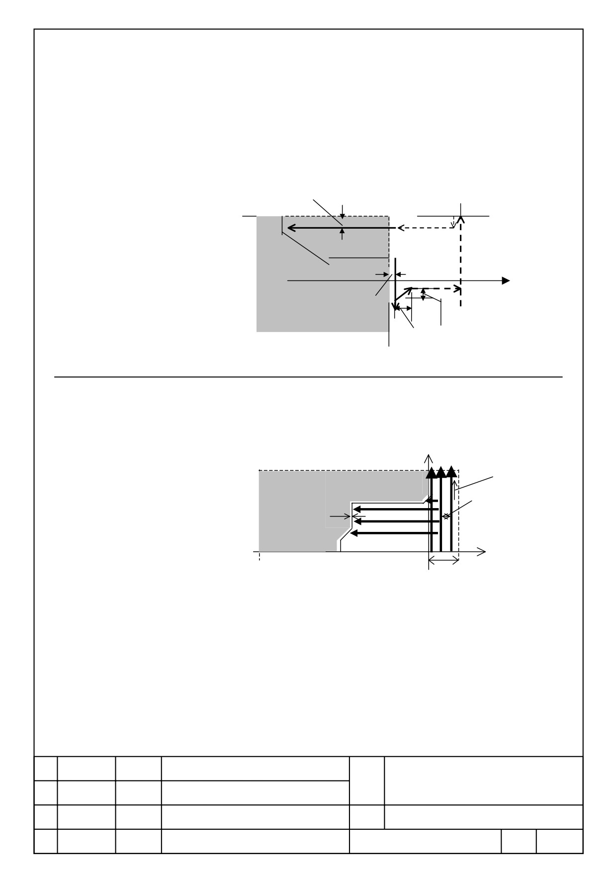
(g) At last returning motion, escape by escape amount to 45°direction as
the following, and then move to “Blank Face + Clearance Z” beside Z
axis by G00.
Move to +X direction “Blank outer point X1” by G00. Then, goes to outer
rough operation.
Outer Rough Cut Depth Q
Blank Face+Clearance Z
X1
Blank Outer X1
Finish Amount
Escape Amount U
Z0
27.2.2
Inner Facing Rough
When inner rough machining, as the figure below cut off the face part
first(①), then inner machining (②) is operated. Cut direction of face part is
always X plus direction as the figure below.
X
Face Cut Feed Rate
Face Cut Depth
Finish Amount
①
②
Z
Face Removal
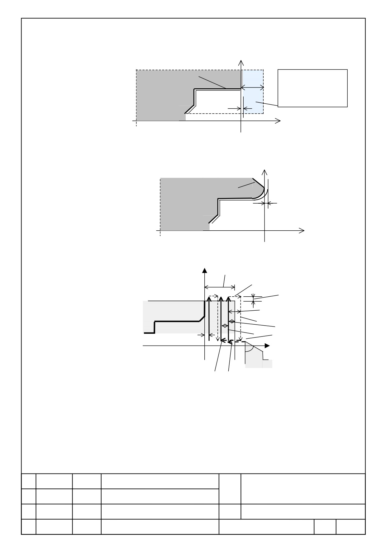
As the figure below, when 1st figure part is begin at X position inner from
outer of blank, and to cut off a face part, make sure to define face part of
blank figure.
FANUC MANUAL GUIDE i
Name
(Series16i/18i/21i-MB/TB)
OPERATOR’S MANUAL
Draw.
B-63874EN/05-1
Ed.
Date
Design
Description
Page
87/100
FANUC LTD.
X
1st Figure Part
On this part figure,
blank definition of
this part is needed to
Face Removal
cut off this face part.
Finish
Amount Z
Z
As upper description, when finish amount is set, finishing amount of face
part remain after completing outer facing rough as figure below.
X
1st Figure Part
Finish Amount
Z
Cut off the face part ① operates as followings.
+X
Face Removal
(c)
Nose Diameter R
X1
Escape Amount U
(d)
Cut Depth Q
Finish Amount W
(b)
Start Point of Machining (Xs, Zs)
X0
●
+Z
Z0
Z1
(e)
(a)
Each operation of face cut off (a)~(e) is the same as outer facing rough only
move direction is changed.
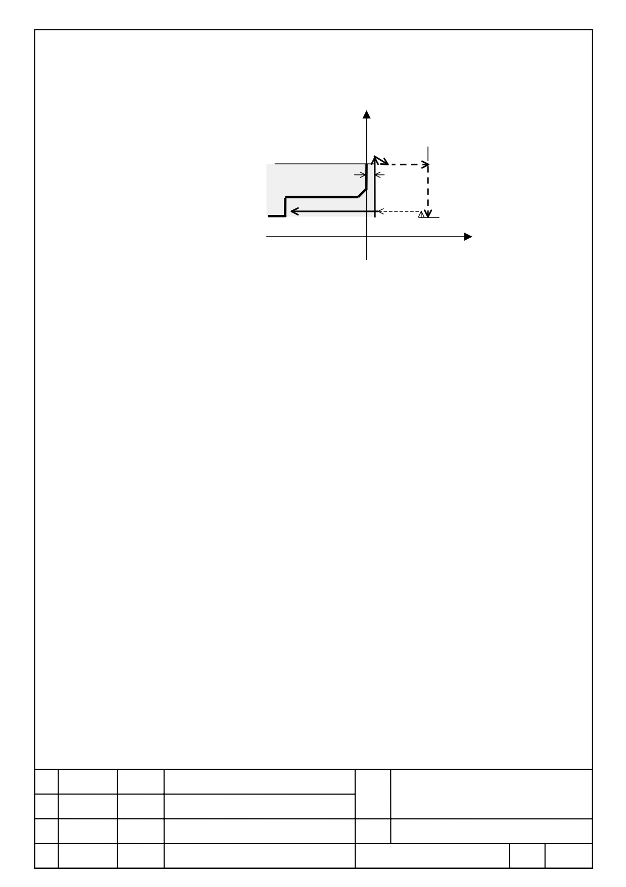
Approach motion to inner rough after the completion of facing is as follows.
As the same as outer facing, after escaping by escape amount to 45°
direction, move to the point ”Blank Face + Clearance Z” beside Z axis
direction by G00. Then move to “Blank inner point Xs” by G00. Then, goes
to inner rough operation.
FANUC MANUAL GUIDE i
Name
(Series16i/18i/21i-MB/TB)
OPERATOR’S MANUAL
Draw.
B-63874EN/05-1
Ed.
Date
Design
Description
Page
88/100
FANUC LTD.
Face
+X Removal
Blank Face+Clearance Z
X1
Finish Amount W
Xs
Blank Inner (*)
X0
+Z
Z0
FANUC MANUAL GUIDE i
Name
(Series16i/18i/21i-MB/TB)
OPERATOR’S MANUAL
Draw.
B-63874EN/05-1
Ed.
Date
Design
Description
Page
89/100
FANUC LTD.
28
Tool Management Function for Series 30i
Tool management function for Series 30i is available.
For details of this function, refer to [V. Tool Management Function] on
[B-63874EN/05 FANUC MANUAL GUIDE i operator’s manual].
FANUC MANUAL GUIDE i
Name
(Series16i/18i/21i-MB/TB)
OPERATOR’S MANUAL
Draw.
B-63874EN/05-1
Ed.
Date
Design
Description
Page
90/100
FANUC LTD.
29
Parameters
#7
#6
#5
#4
#3
#2
#1
#0
14705
#7
#5
#4
#1
#0
#0 Make the shortcut function of to soft key
0 : available.
1 : invalid.
#1 Cursor position after the copy are
0 : Return to the top block of a selected range.
1 : Keep a cursor to the end block of a selected range.
#4 Softkey [T-OFS]
0 : Display.
1 : Undisplay.
#5 Softkey [TOOL]
0 : Undisplay.
1 : Display.
#7 Tool icon display function and shortcut function to tool database screen
are
0 : not enabled.
1 : enabled.
14717
Axis Number of B Axis
Data Range :
0 ~ Number of control axis
14842
Drawing coordination of free figure cylinder blank figure screen.
=0 Same as 6
=1 Plane figure Horizontal axis =+Y, Vertical axis =+Z
=5 Plane figure Horizontal =+Y, Vertical axis =+Z
=6 Plane figure Horizontal =+Y, Vertical axis =-Z
Z
Y
Z
Y
Z
Y
1
5
6
FANUC MANUAL GUIDE i
Name
(Series16i/18i/21i-MB/TB)
OPERATOR’S MANUAL
Draw.
B-63874EN/05-1
Ed.
Date
Design
Description
Page
91/100
FANUC LTD.
14845
TLTAB
Set the display position of each tab of tool management data,
magazine information, tool offset, and tool information.
1digit
Tool Management Data Tab
10 place
Magazine Data Tab
100 place
Tool Offset Tab
1000 place
Tool Data Tab
Set 1~4 to each value to set a displaying order of a tab.
Tab is no displayed when 0 is set. When 0 is set to all, it is displayed
by default sorting.
Default sorting display is as follows.
1st
Tool Management Data Tab
2nd
Magazine Data Tab
3rd
Tool Offset Tab
4th
Tool Data Tab
Please input the figure of four digits to this parameter. And the
figure of each digit must not overlap.
#7
#6
#5
#4
#3
#2
#1
#0
27002
#5
#4
#4 Display/Undisplay a Side Finish Feed Rate on free figure for milling.
0 : Undisplay.
1 : Display.
#5 At entry screen of Pocketing/Embossing/Contouring/Grooving cycle
0 : Conventional order of tool cut depth and finish amount.
1 : Switch the order of tool cut depth and finish amount.
#7
#6
#5
#4
#3
#2
#1
#0
27003
#3
#2
#1
#0
27003#0=0, 27003#1=0, 27003#2=0, 27003#3=1,
Axis structure of machining center is X/Y/Z/B.
Displaying a menu of blank round Y-axis direction in blank
definition.
#7
#6
#5
#4
#3
#2
#1
#0
27004
#3
#2
#1
#0
P27004#0=1, 27004#1=0, 27004#2=0, 27004#3=1,
The following menus are displayed.
FANUC MANUAL GUIDE i
Name
(Series16i/18i/21i-MB/TB)
OPERATOR’S MANUAL
Draw.
B-63874EN/05-1
Ed.
Date
Design
Description
Page
92/100
FANUC LTD.
Grooving : Grooving (B axis) --- G1054
Hole Figure : B axis Hole figure (on arc) YB Plane --- G1777
B axis Hole figure (random points) YB Plane --- G1778
Groove Figure :B axis groove figure of YB Plane --- G1775
Y axis groove figure of YB Plane --- G1776
NOTE
3 After set the parameter No.27003, [F] key must be pressed at a
screen of NOW LOADING after power has been restored. Required
parameter is automatically set. (When parameter is set
automatically, a message ”NOW SETTING PARAMETERS” is
displayed at bottom left corner.)
4 By set the No.27003, the following parameter related to display are
automatically set.
No.27000#6
No.27000#1
No.27000#4
No.27100#4
No.27001#0,#1
No.14702#1
Convert
No.27060#1
Change Hole
Face
Face
Rotation Axis
Select Spindle
Coordinatio
PR1
Machining
Position-M
Position -T
Name
n
0
0
0
0
1
0
1
ML0
0
0
0
0
0
0
1
ML1
0
0
0
0
0
0
1
ML2
0
0
0
0
0
0
1
ML3
No.27004#0
No.27004#1
No.27004#2
No.27004#3
No.27314#0,#1
No.27334
Menu 1
Menu 2
OP 1
OP 2
Set Blank Figure
Set Rectangular Blank
ML0
1
0
0
0
0
0
ML1
0
0
0
0
0
0
ML2
1
0
1
0
0
0
ML3
1
0
0
1
1
1
27013
MSTOP
MSTOP : M code for Spindle stop in Fine Boring
=0 Output M05 for Spindle stop
≠0 Set M code number for Spindle stop
For Fine Boring for M series with End Feedrate (G1005) and Fine Boring
for T series (G1105, G1115)
27014
MORIE
FANUC MANUAL GUIDE i
Name
(Series16i/18i/21i-MB/TB)
OPERATOR’S MANUAL
Draw.
B-63874EN/05-1
Ed.
Date
Design
Description
Page
93/100
FANUC LTD.
MORIE : M code for Spindle orientation in Fine Boring
=0 Output M19 for Spindle orientation
≠0 Set M code number for Spindle orientation
For Fine Boring for M series with End Feedrate (G1005) and Fine Boring
for T series (G1115)
27018
SRCHBLNK
Blank form data is automatically copied at figure entry, reused function is
available by setting the below parameter.
SRCHBLNK : Block number when searching a blank form block.
When a standard value is (=0), block number to
search is 100.
#7
#6
#5
#4
#3
#2
#1
#0
27020
#6
#5
#4
#3
#0
#0 Input Item [GO PAST AMOUNT SET (H)] for drilling
0 : Undisplay.
1 : Display.
#3 In Fine Boring for T series:
0 : Output M code for spindle stop before an oriented spindle stop in
Fine Boring (G1115).
Output M code for spindle stop in Fine Boring (G1105).
1 : Not output M code for spindle stop in Fine Boring (G1105, G1115).
#5/#4
:
Set the axis and direction in which the tool in Fine Boring for T
series (G1115) is got free. #5 and #4 are set as shown below by
plane selection.
#5
#4
G17
G18
G19
0
0
+X
+Z
+Y
0
1
-X
-Z
-Y
1
0
+Y
+X
+Z
1
1
-Y
-X
-Z
#6 Set the direction in which the tool in Fine Boring for T series (G1105)
is got free.
0 :
+X direction is free.
1 :
-X direction is free.
FANUC MANUAL GUIDE i
Name
(Series16i/18i/21i-MB/TB)
OPERATOR’S MANUAL
Draw.
B-63874EN/05-1
Ed.
Date
Design
Description
Page
94/100
FANUC LTD.
#7
#6
#5
#4
#3
#2
#1
#0
27061
#5
#5 Display / Undisplay an input item [Cut Angle] at pocketing.
0 : Display.
1 : Undisplay.
#7
#6
#5
#4
#3
#2
#1
#0
27095
#2
#1
#0
#0 Set parameter No.27095#0 to exchange the input items [Bottom Thickness] and
[Side Thickness] at cycle entry screen and figure entry screen.
0 : Input bottom / side thickness at cycle entry screen.
1 : Input bottom / side thickness at figure entry screen.
#1 Blank form data is automatically copied at figure entry, reused function is
available by setting the below parameter.
0 : Not reuse the blank form data for figure data at machining.
(Reuse soft key is not displayed at figure entry screen.)
1 : Reuse the blank form data for figure data at machining.
(Reuse soft key is displayed at figure entry screen)
#2 Polygon pattern of fixed figure is
0 : Undisplay.
1 : Display.
#7
#6
#5
#4
#3
#2
#1
#0
27102
#4
#3
#3 Display / undisplay [Grinding Amount] at free figure of ZX plane for turning.
0 : Undisplay.
1 : Display.
#4 Display / undisplay a semi finish feed rate on a free figure of ZX plane at
turning.
0 : Undisplay.
1 : Display.
#7
#6
#5
#4
#3
#2
#1
#0
27120
#2
#2 Simultaneous Facing of Turning at outer / inner machining
0 : unavailable.
1 : available.
FANUC MANUAL GUIDE i
Name
(Series16i/18i/21i-MB/TB)
OPERATOR’S MANUAL
Draw.
B-63874EN/05-1
Ed.
Date
Design
Description
Page
95/100
FANUC LTD.
27131
CDOVR
CDOVR Override of face cut depth with Simultaneous Facing of Turning
1~200%, 1% Unit
Set 0 is considered as 100%
27132
CFOVR
CFOVR Override of face cut feed rate with Simultaneous Facing
1~200%, 1% Unit
Set 0 is considered as 100%
#7
#6
#5
#4
#3
#2
#1
#0
27140
#1
#1 Display / Undisplay [Threading Direction]
0 : Undisplay.
1 : Display.
#7
#6
#5
#4
#3
#2
#1
#0
27170
#1
#1
0 : Undisplay Roughing Type of Turning Grooving.
1 : Display Roughing Type of Turning Grooving.
(Roughing by versatile tool is available)
27178
Depth direction Minimum cut depth of Turning Grooving (Roughing) by
versatile tool.
#7
#6
#5
#4
#3
#2
#1
#0
27195
#1
#0
#0 Counter tapping by work rotation
0 : Disabled.
1 : Enabled.
#1 Counter tapping by rotating tool
0 : Disabled.
1 : Enabled.
The below parameter 27196~27211 are available only when counter
tapping (both or either 27195<#0>, and <#1> is set to “1”) is available.
FANUC MANUAL GUIDE i
Name
(Series16i/18i/21i-MB/TB)
OPERATOR’S MANUAL
Draw.
B-63874EN/05-1
Ed.
Date
Design
Description
Page
96/100
FANUC LTD.
27196
S1TTMN
S1TTMN
M code command before the normal tapping of spindle 1
Setting Range 0~65535
No output when 0 is set. This data is set individually per
turret (system) in multi path system.
27197
S1TTMR
S1TTMR
M code command before the counter tapping of spindle 1
Setting Range 0~65535
No output when 0 is set。This data is set individually per
turret (system) in multi path system.
27198
S2TTMN
S2TTMN
M code command before the normal tapping of spindle 2
Setting Range 0~65535
No output when 0 is set This data is set individually per
turret (system) in multi path system.
27199
S2TTMR
S2TTMR
M code command before the counter tapping of spindle 2
Setting Range 0~65535
No output when 0 is set。This data is set individually per
turret (system) in multi path system.
27200
S3TTMN
S3TTMN
M code command before the normal tapping of spindle 3
Setting Range 0~65535
No output when 0 is set This data is set individually per
turret (system) in multi path system.
27201
S3TTMR
S3TTMR
M code command before the counter tapping of spindle 3
Setting Range 0~65535
No output when 0 is set. This data is set individually per
turret (system) in multi path system.
27202
S1NMLM
S1NMLM
M code for rotating spindle 1.
Setting Range 0~65535
FANUC MANUAL GUIDE i
Name
(Series16i/18i/21i-MB/TB)
OPERATOR’S MANUAL
Draw.
B-63874EN/05-1
Ed.
Date
Design
Description
Page
97/100
FANUC LTD.
M3 is output when 0 is set. This data is set individually per
turret (system) in multi path system.
27203
S1RVSM(Reserved for counter rotation of spindle 1)
(For each turret (system))
27204
S2NMLM
S2NMLM M code for rotating spindle 2.
Setting Range 0~65535
M3 is output when 0 is set This data is set individually per
turret (system) in multi path system.
27205
S2RVSM(Reserved for counter rotation of spindle 2)
(For each turret (system))
27206
S3NMLM
S3NMLM M code for rotating spindle 3.
Setting Range 0~65535
M3 is output when 0 is set This data is set individually per
turret (system) in multi path system.
27207
S3RVSM(Reserved for counter rotation of spindle 3)
(For each turret (system))
27208
MILTMN
MILTMN
M code command before the normal tapping by rotating tool
Setting Range 0~65535
M3 is output when 0 is set This data is set individually per
turret (system) in multi path system.
27209
MILTMR
MILTMR
M code command before the counter tapping by rotating tool
Setting Range 0~65535
M3 is output when 0 is set This data is set individually per
turret (system) in multi path system.
27210
MLNMLM
MLNMLM
M code for rotating tool
Setting Range 0~65535
<Related parameter:No.27195#3(MLT)>
FANUC MANUAL GUIDE i
Name
(Series16i/18i/21i-MB/TB)
OPERATOR’S MANUAL
Draw.
B-63874EN/05-1
Ed.
Date
Design
Description
Page
98/100
FANUC LTD.
M3 is output when 0 is set This data is set individually per
turret (system) in multi path system.
27211
MLRVSM(Reserved for counter rotation of tool rotation)
(For each turret (system))
#7
#6
#5
#4
#3
#2
#1
#0
27314
#1
#0
Whether to display a blank figure of Y-axis direction is depend on the
following parameter settings.
#0
0 : Display a blank figure of Z-axis direction at definition screen of blank
figure.
1 : Undisplay a blank figure of Z-axis direction at definition screen of
blank figure.
#1
0 : Undisplay a blank figure of Y-axis direction at definition screen of blank
figure.
1 : Display a blank figure of Y-axis direction at definition screen of
blank figure.
※Because rectangular blank figure is common with each axis rotation, it
displays always with no relation to the parameter above.
27334
Center axis of work rotation for rectangular blank figure at simulation.
=0 Z-axis direction
=1 Y-axis direction
#7
#6
#5
#4
#3
#2
#1
#0
27384
#0
#0
0 : When versatile tool is drew by animation, tip position is drew in front.
1 : When versatile tool is drew by animation, tip position is drew in rear.
27385
Holder length when versatile tool is drew by animation.
Data Unit : When input unit by milli (0000#2=0):0.001 mm
When input unit by inch (0000#2=1):0.0001 inch
When input 0 by millimeter input unit (0000#2=0), it
automatically set to 50mm
FANUC MANUAL GUIDE i
Name
(Series16i/18i/21i-MB/TB)
OPERATOR’S MANUAL
Draw.
B-63874EN/05-1
Ed.
Date
Design
Description
Page
99/100
FANUC LTD.

When input 0 by inch (0000#2=1), it automatically set to
1.9685inch.
27386
Holder width when versatile tool is drew by animation.
Data Unit : When input unit by milli (0000#2=0):0.001 mm
When input unit by inch (0000#2=1):0.0001 inch
When input 0 by millimeter input unit (0000#2=0), it
automatically set to 14mm.
When input 0 by inch (0000#2=1), it automatically set to
0.5512inch.
FANUC MANUAL GUIDE i
Name
(Series16i/18i/21i-MB/TB)
OPERATOR’S MANUAL
Draw.
B-63874EN/05-1
Ed.
Date
Design
Description
Page
100/100
FANUC LTD.