FANUC MANUAL GUIDE i. OPERATOR’S MANUAL - page 32
21.2. Machining Operation
21.2.1
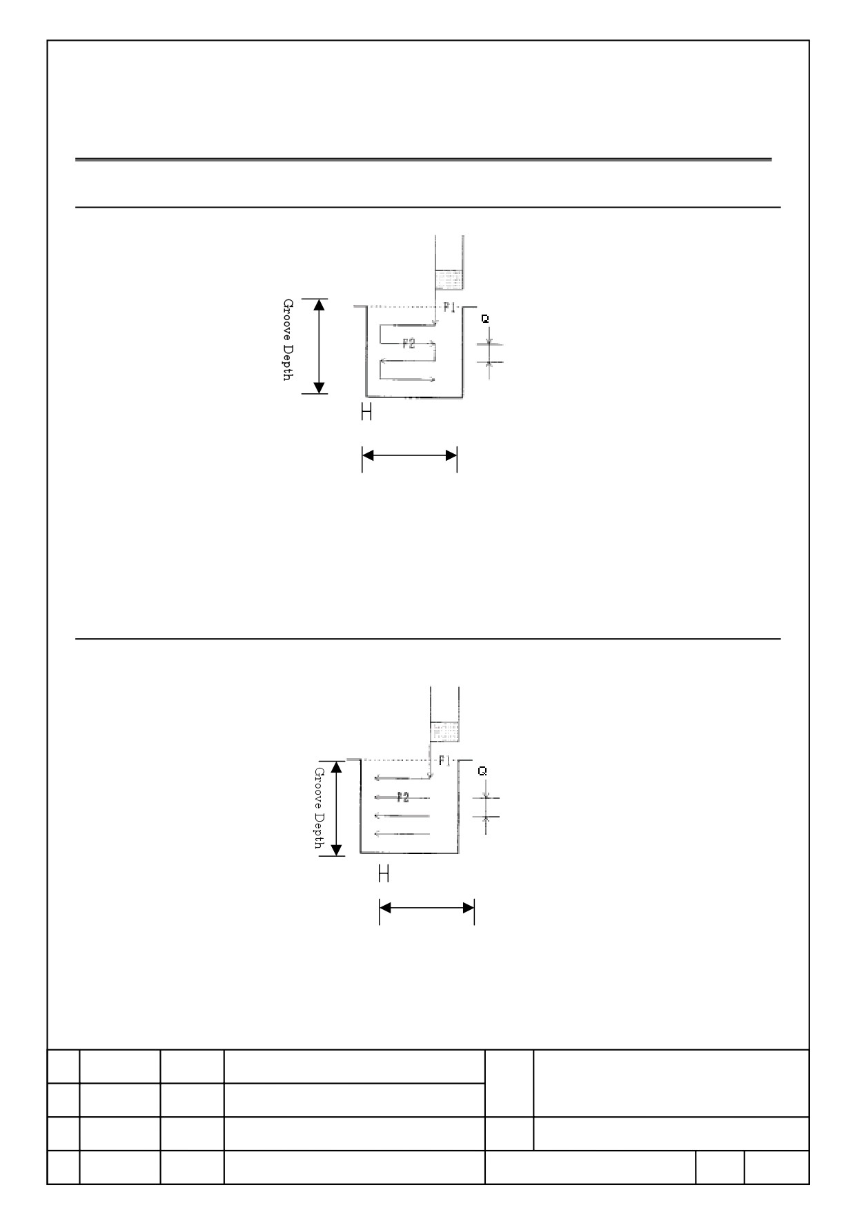
Versatile ZIGZAG
C*
D
F1:Groove Depth Direction Feed Rate
F2:Groove Width Direction Feed Rate
D:Groove Width
Q:Pecking Cut Depth(X axis direction)
C*:Side Finish Amount
21.2.2
Versatile 1 Direction
C*
D
F1:Groove Depth Direction Feed Rate
F2:Groove Width Direction Feed Rate
D:Groove Width
Q:Pecking Cut Depth(X axis direction)
FANUC MANUAL GUIDE i
Name
(Series16i/18i/21i-MB/TB)
OPERATOR’S MANUAL
Draw.
B-63874EN/05-1
Ed.
Date
Design
Description
Page
56/100
FANUC LTD.
C*:Side Finish Amount
21.3. Improvement of Tool Database Function
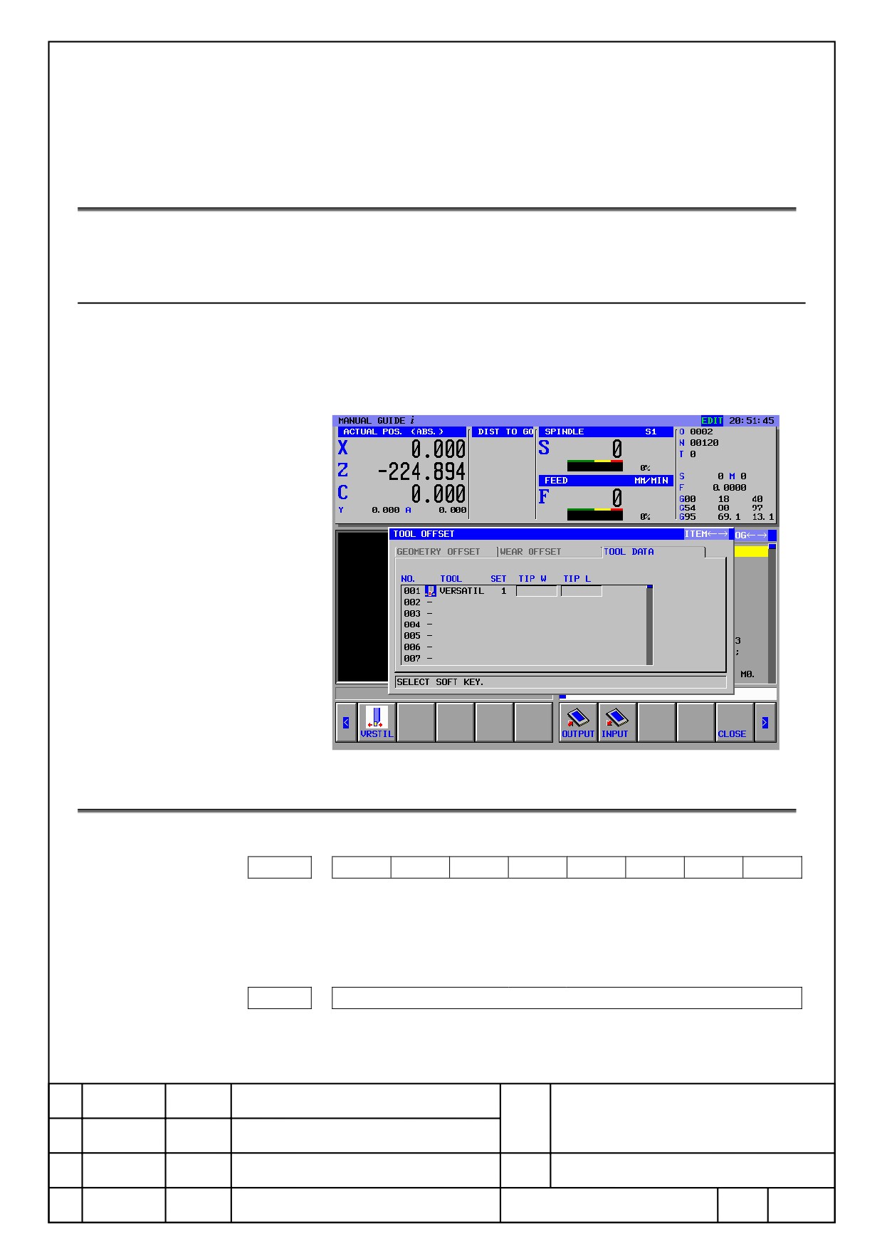
Versatile tool is added to tool kind of tool database function.
21.3.1
Tool Offset Screen
[Tool Data] tab at tool offset screen is displayed. Then, press right page soft
key several times to display [VERSTL] soft key. By pressing this soft key to
select a versatile tool.
21.4. Parameters
#7
#6
#5
#4
#3
#2
#1
#0
27170
#1
#1
0 : Undisplay Roughing Type of Turning Grooving.
1 : Display Roughing Type of Turning Grooving.
(Roughing by versatile tool is available)
27178
Depth direction Minimum cut depth of Turning Grooving
(Roughing) by versatile tool.
FANUC MANUAL GUIDE i
Name
(Series16i/18i/21i-MB/TB)
OPERATOR’S MANUAL
Draw.
B-63874EN/05-1
Ed.
Date
Design
Description
Page
57/100
FANUC LTD.
#7
#6
#5
#4
#3
#2
#1
#0
27384
#0
#0
0 : When versatile tool is drew by animation, tip position is drew in
front.
1 : When versatile tool is drew by animation, tip position is drew in
rear.
27385
Holder length when versatile tool is drew by animation.
Data Unit : When input unit by milli (0000#2=0):0.001 mm
When input unit by inch (0000#2=1):0.0001 inch
When input 0 by millimeter input unit (0000#2=0), it automatically set to
50mm
When input 0 by inch (0000#2=1), it automatically set to 1.9685inch.
27386
Holder width when versatile tool is drew by animation.
Data Unit : When input unit by milli (0000#2=0):0.001 mm
When input unit by inch (0000#2=1):0.0001 inch
When input 0 by millimeter input unit (0000#2=0), it automatically set to
14mm.
When input 0 by inch (0000#2=1), it automatically set to 0.5512inch.
FANUC MANUAL GUIDE i
Name
(Series16i/18i/21i-MB/TB)
OPERATOR’S MANUAL
Draw.
B-63874EN/05-1
Ed.
Date
Design
Description
Page
58/100
FANUC LTD.
22
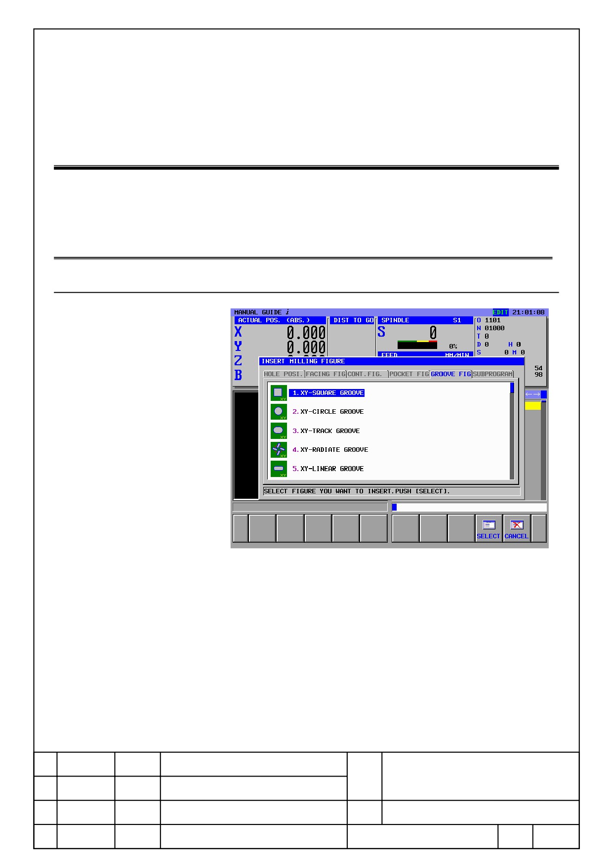
Linear Groove for XY Plane
Add [XY plane linear groove] on grooving figure at milling cycle. By adding
this, linear groove is possible to operate.
22.1. Cycle Input Screen
22.1.1
Figure Selection Screen
FANUC MANUAL GUIDE i
Name
(Series16i/18i/21i-MB/TB)
OPERATOR’S MANUAL
Draw.
B-63874EN/05-1
Ed.
Date
Design
Description
Page
59/100
FANUC LTD.
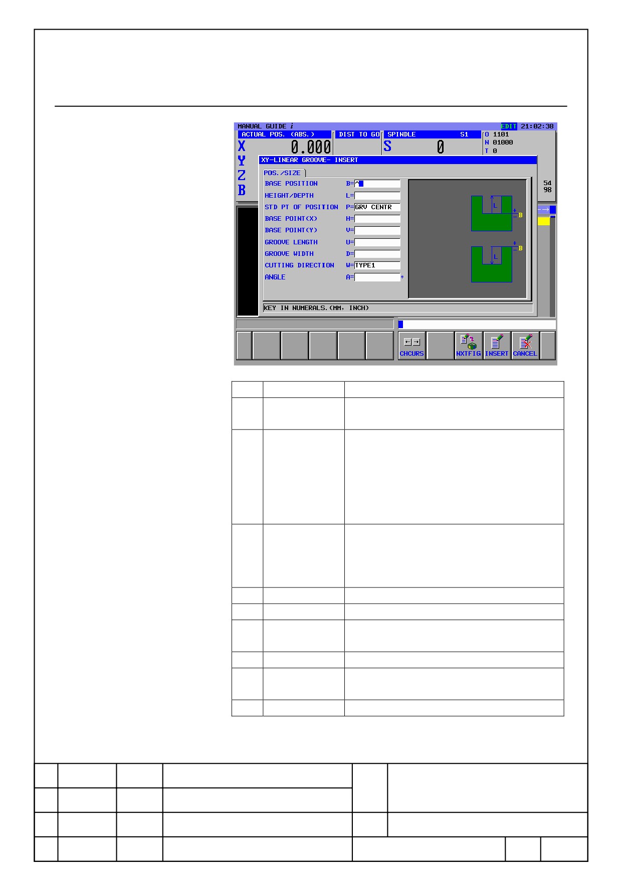
22.1.2 Linear Groove for XY Plane Input Screen
Input Item
Meaning
B
Base Position
Z-axis coordination at either upper face of work
to groove, or bottom of groove.
L
Height / Depth
Upper face of work is selected as a standard
position, and distance to the bottom of
groove is set by negative value. →Depth
Bottom of groove is selected as a standard
position, and distance to upper face of
groove is set by positive value. →Height
P
Standard Point
Position of standard position on coordination X
of Position
and coordination Y
1:Center of Groove
2:Corner of Groove
3:Center circle of corner groove
H
Base Point (X)
Value of coordination X at standard position
V
Base Point (Y)
Value of coordination Y at standard position
U
Grooving
Length of a grooving
Length
D
Grooving Width
Width of a grooving
W
Cutting
Direction of cutting
Direction
A
Angle
Slope angle from a position of standard point.
FANUC MANUAL GUIDE i
Name
(Series16i/18i/21i-MB/TB)
OPERATOR’S MANUAL
Draw.
B-63874EN/05-1
Ed.
Date
Design
Description
Page
60/100
FANUC LTD.
22.2. Format of Program
22.2.1
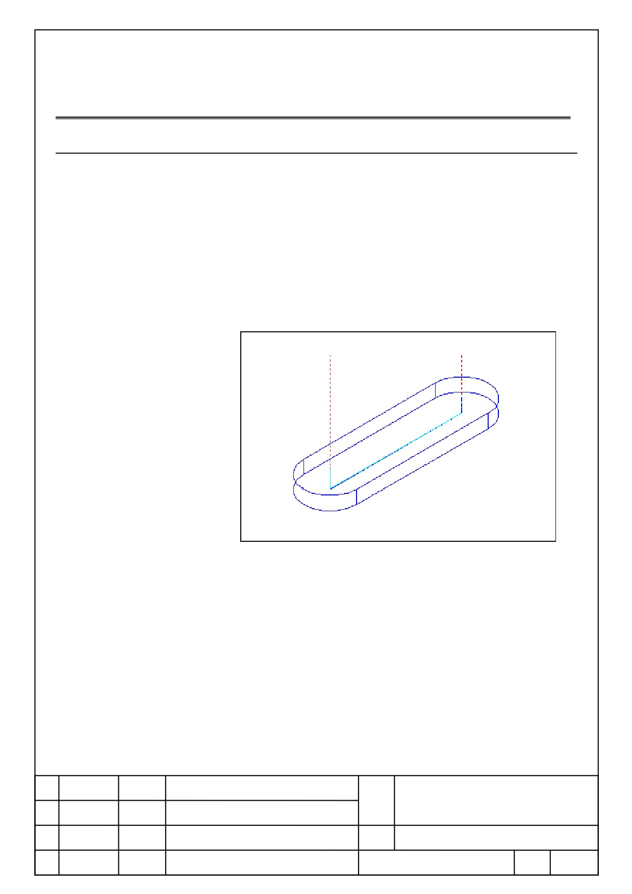
Roughing of Linear Groove
When creating a program of linear groove roughing, enter a grooving
process block and linear groove block.
(Example Program)
G1050 (Grooving Rough)
G1224 (Linear Groove)
Tool path when a groove width of linear groove roughing is the same as tool
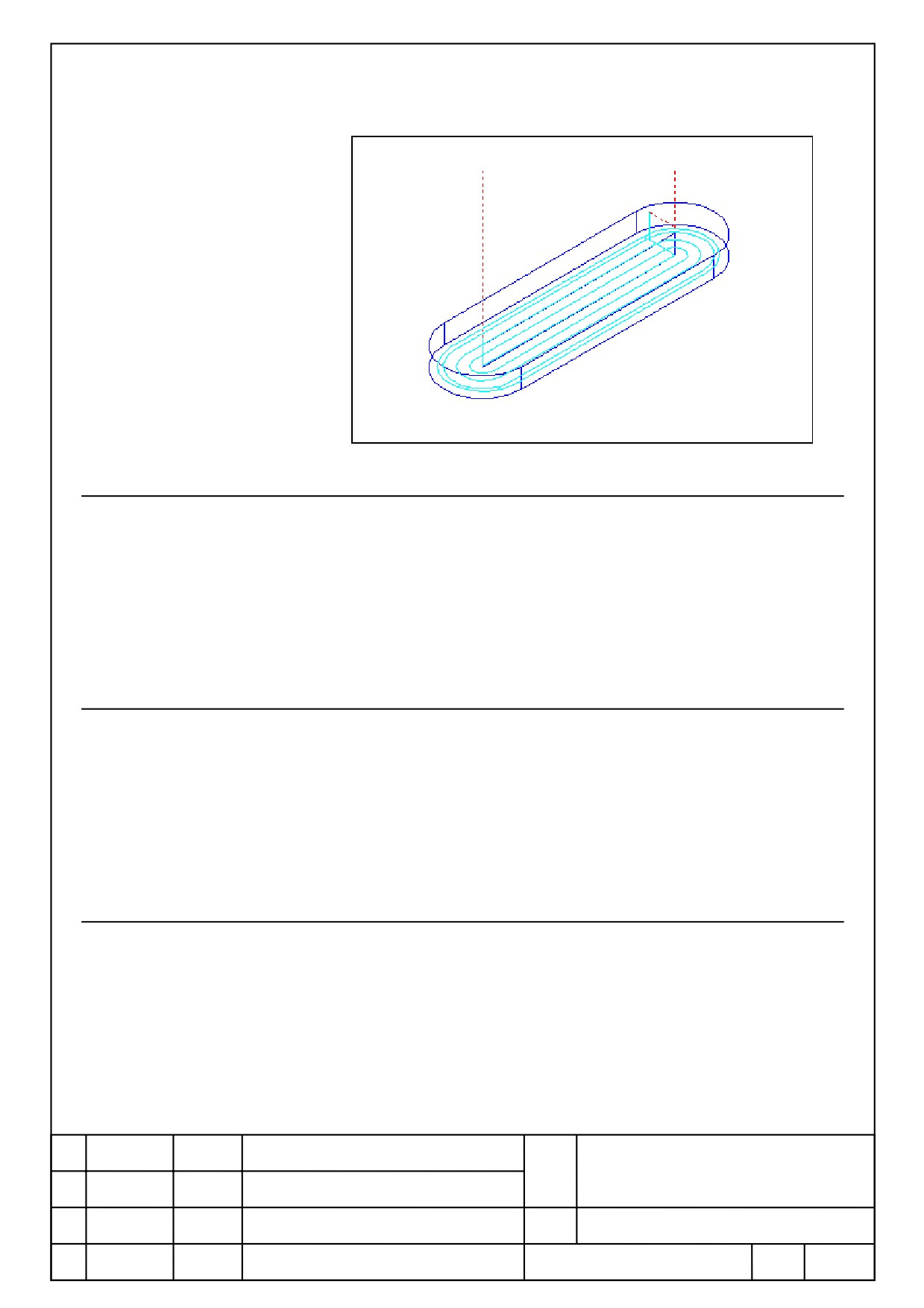
diameter.
Tool path when a groove width of linear groove roughing is larger than tool
diameter.
FANUC MANUAL GUIDE i
Name
(Series16i/18i/21i-MB/TB)
OPERATOR’S MANUAL
Draw.
B-63874EN/05-1
Ed.
Date
Design
Description
Page
61/100
FANUC LTD.
22.2.2
Bottom Finishing of Linear Groove
When creating a program of linear groove bottom finishing, enter a grooving
process block and linear groove block.
Tool path is the same as linear groove roughing.
(Example Program)
G1051 (Bottom Finish Grooving)
G1224 (Linear Groove)
22.2.3
Side Finishing of Linear Groove
When creating a program of linear groove side finishing, enter a grooving
process block and linear groove block.
Tool path is the same when linear groove is defined on free figure.
(Example Program)
G1052 (Side Finish Grooving))
G1224 (Linear Groove)
22.2.4
Chamfering of Linear Groove
When creating a program of linear groove chamfering, enter a grooving
process block and linear groove block.
Tool path is the same when linear groove is defined on free figure.
(Example Program)
G1053 (Chamfering Grooving)
G1224 (Linear Groove)
FANUC MANUAL GUIDE i
Name
(Series16i/18i/21i-MB/TB)
OPERATOR’S MANUAL
Draw.
B-63874EN/05-1
Ed.
Date
Design
Description
Page
62/100
FANUC LTD.
23
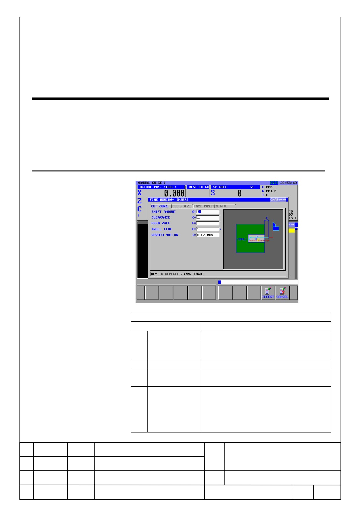
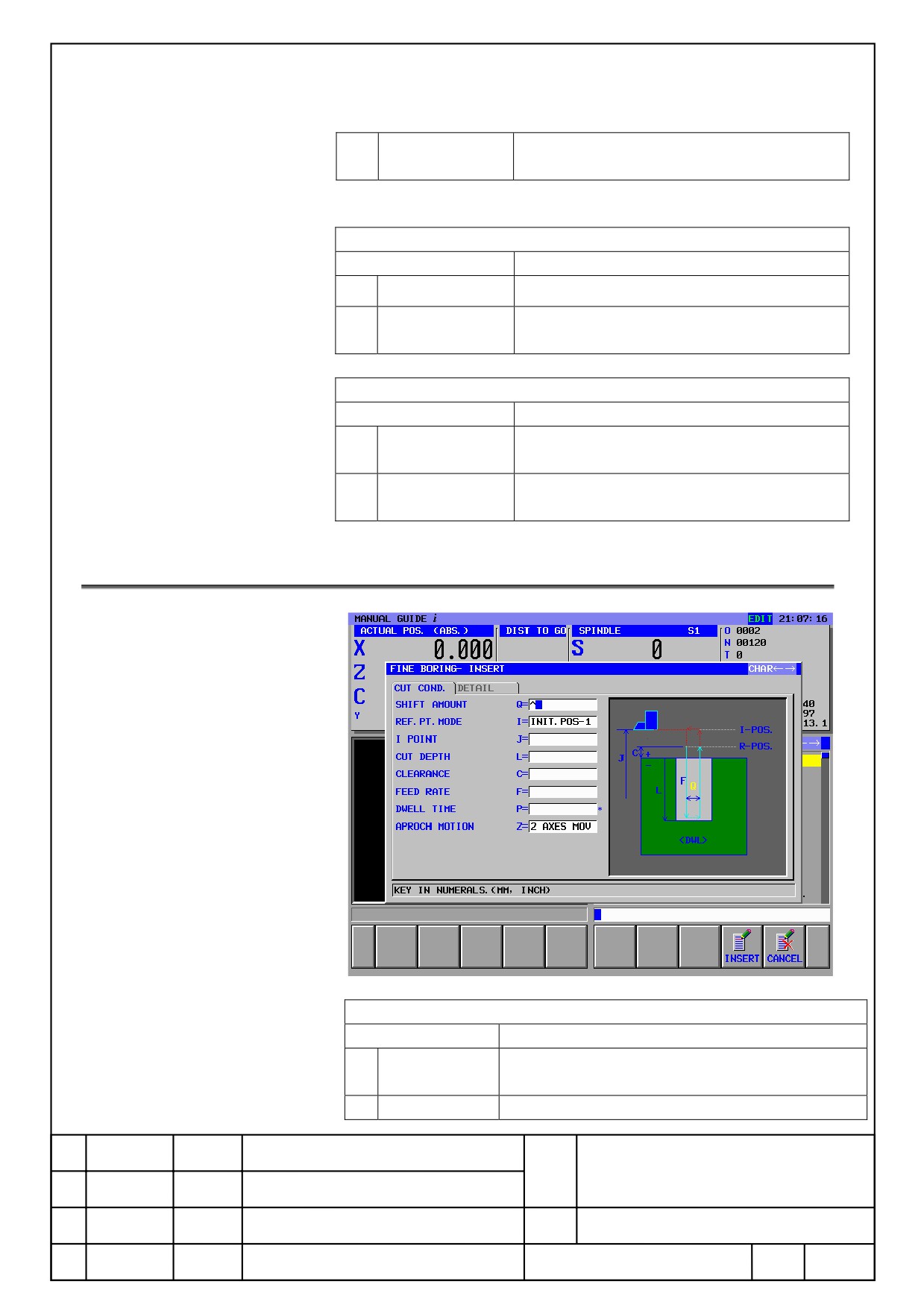
Fine Boring for Turning
Fine Boring is added for turning.
(1)
Fine Boring(Work Rotation for Turning)
: G1105
(2)
Fine Boring(Tool Rotation for Turning)
: G1115
23.1. Fine Boring(Work Rotation for Turning): G1105
Cut Condition
Data Items
Meanings
Q
Shift Amount
Bottom Shift Amount(Radius Value)(Copy)
C
Clearance
Distance between work surface and R point.
(Radius Value, Positive Value)(Copy)
F
Feed Rate
Feed Rate at Cutting(Positive Value)(Copy)
P*
Dwell Time
Dwell time at the Bottom(Second Bit, Positive
Value)(Copy)
Z
Approach Motion
[Z→X]:When moving from current position to
start point, X axis moves after Z axis movement.
[X→Z]:When moving from current position to
start point, X axis moves after Z axis
movement.(Default)
FANUC MANUAL GUIDE i
Name
(Series16i/18i/21i-MB/TB)
OPERATOR’S MANUAL
Draw.
B-63874EN/05-1
Ed.
Date
Design
Description
Page
63/100
FANUC LTD.
[2 axis]:When moving from current position to
start point, X/Z axis move at once.
Position / Measurement
Data Items
Meanings
B
Base Position
Z axis coordination value at work surface
L
Cut Depth
Available depth of hole(Radius Value, Negative
Value)
Details
Data Items
Meanings
D
Cut Depth at
Cut depth when cutting with federate changed at
Ending
cut ending.
E
Feed rate at
Cut feed rate when cutting with federate
Ending
changed at cut ending.
23.2. Fine Boring(Tool Rotation for Turning): G1115
Cut Condition
Data Items
Meanings
Q
Shift Amount
Shift Amount after the Spindle orientation at the
Bottom(Radius Value)(Copy)
I
Return Mode
[Point I-1]:Move between holes by R point Return,
FANUC MANUAL GUIDE i
Name
(Series16i/18i/21i-MB/TB)
OPERATOR’S MANUAL
Draw.
B-63874EN/05-1
Ed.
Date
Design
Description
Page
64/100
FANUC LTD.
and move to the last by I point.(Default)
[Point I-2]:All movement between holes by I point
return including a last return mode.
[Point R]: All movement between holes by R point
return including a last return mode.
J
Point I
Coordination of Point I(Copy)
Coordination
L
Available Depth
Available Depth of Hole(Radius Value, Negative
Value)
C
Clearance
Distance between work surface and R point(Radius
Value, Positive Value)(Copy)
F
Feed Rate
Feed Rate at Cutting(Positive Value)(Copy)
P*
Dwell Time
Dwell Time at the Bottom(Second Bit, Positive Value)
(Copy)
Z
Approach
[Z→X]:When moving from current position to start
Motion
point, X axis moves after Z axis movement.
[X→Z]:When moving from current position to start
point, X axis moves after Z axis
movement.(Default)
[2 axis]:When moving from current position to start
point, X/Z axis move at once.
Details
Data Items
Meanings
D
Cut Depth at
Cut depth when cutting with feed rate changed at cut
Ending
ending.
E*
Feed rate at
Cut feed rate when cutting with feed rate changed at
Ending
cut ending.
23.3.
Parameters
27013
MSTOP
MSTOP : M code for Spindle stop in Fine Boring
=0 Output M05 for Spindle stop
≠0 Set M code number for Spindle stop
For Fine Boring for M series with End Feedrate (G1005) and Fine Boring
for T series (G1105, G1115)
FANUC MANUAL GUIDE i
Name
(Series16i/18i/21i-MB/TB)
OPERATOR’S MANUAL
Draw.
B-63874EN/05-1
Ed.
Date
Design
Description
Page
65/100
FANUC LTD.
27014
MORIE
MORIE : M code for Spindle orientation in Fine Boring
=0 Output M19 for Spindle orientation
≠0 Set M code number for Spindle orientation
For Fine Boring for M series with End Feedrate (G1005) and Fine Boring
for T series (G1115)
#7
#6
#5
#4
#3
#2
#1
#0
27020
#6
#5
#4
#3
In Fine Boring for T series:
#3
0 : Output M code for spindle stop before an oriented spindle stop in Fine
Boring (G1115).
Output M code for spindle stop in Fine Boring (G1105).
1 : Not output M code for spindle stop in Fine Boring (G1105, G1115).
#5/ #4 : Set the axis and direction in which the tool in Fine Boring for T series
(G1115) is got free. #5 and #4 are set as shown below by plane selection.
#5
#4
G17
G18
G19
0
0
+X
+Z
+Y
0
1
-X
-Z
-Y
1
0
+Y
+X
+Z
1
1
-Y
-X
-Z
Set the direction in which the tool in Fine Boring for T series (G1105) is got free.
#6
0 :
+X direction is free.
1 :
-X direction is free.
FANUC MANUAL GUIDE i
Name
(Series16i/18i/21i-MB/TB)
OPERATOR’S MANUAL
Draw.
B-63874EN/05-1
Ed.
Date
Design
Description
Page
66/100
FANUC LTD.
24
Milling Machining of Workpiece Rotating
round Y-axis
24.1.
Outline
This function is complied with the Milling machine which machines a
workpiece rotating round Y-axis.
NOTE
1 This function is available for only Milling machine.
2 Set the number of B axis as the rotational axis of workpiece.
24.1.1
Applied Milling Cycle
In Hole machining and Grooving, this function is applied as follows.
(1) Hole Machining
Only B axis hole machining on cylindrical face (YB) are applied.
(2) Grooving
B axis grooving and Y-axis grooving on cylindrical face are appplied.
NOTE
1 Turning Cycle cannot be used.
2 Polar Coordinate Interpolation cannot be used.
3 Cylindrical Interpolation cannot be used.
24.1.2
Machining Simulation
Machining simulation of workpiece rotating round Y-axis is available.
NOTE
1 Turning Simulation cannot be operated.
2 Simulation with Polar Coordinate Interpolation cannot be operated.
3 Simulation with Cylindrical Interpolation cannot be operated.
4 Since rotational axis of workpiece is decided by parameter, the
rotational axis cannot be changed while machining simulation.
FANUC MANUAL GUIDE i
Name
(Series16i/18i/21i-MB/TB)
OPERATOR’S MANUAL
Draw.
B-63874EN/05-1
Ed.
Date
Design
Description
Page
67/100
FANUC LTD.
5 While machining simulation of the workpiece rotating around Y-axis,
the axis name is displayed as X, Y, and -Z
24.2.
Details
24.2.1
Machining Type Block
The following menu and G code are added for Milling.
1.
Grooving Block
Groove (B axis) : G1054
24.2.2
Figure Type Block
The following menu and G code are added for each Milling.
1. Hole position block
B axis hole (arc) figure of cylindrical face (YB) : G1777
B axis hole (random points) figure of cylindrical face (YB) : G1778
2. Groove figure block
B axis groove figure of cylindrical face: G1775
Y axis groove figure of cylindrical face: G1776
NOTE
1 When the parameter P27004#3 = 1, the items of YZ plane is not
displayed.
24.2.3
Machining Type Block Entry
Press [CYCLE] soft key, menu screen for selecting milling cycle is opened.
And select tab “GROOVING”, the menu “Grooving (B axis)” are displayed as
the following figure.
FANUC MANUAL GUIDE i
Name
(Series16i/18i/21i-MB/TB)
OPERATOR’S MANUAL
Draw.
B-63874EN/05-1
Ed.
Date
Design
Description
Page
68/100
FANUC LTD.
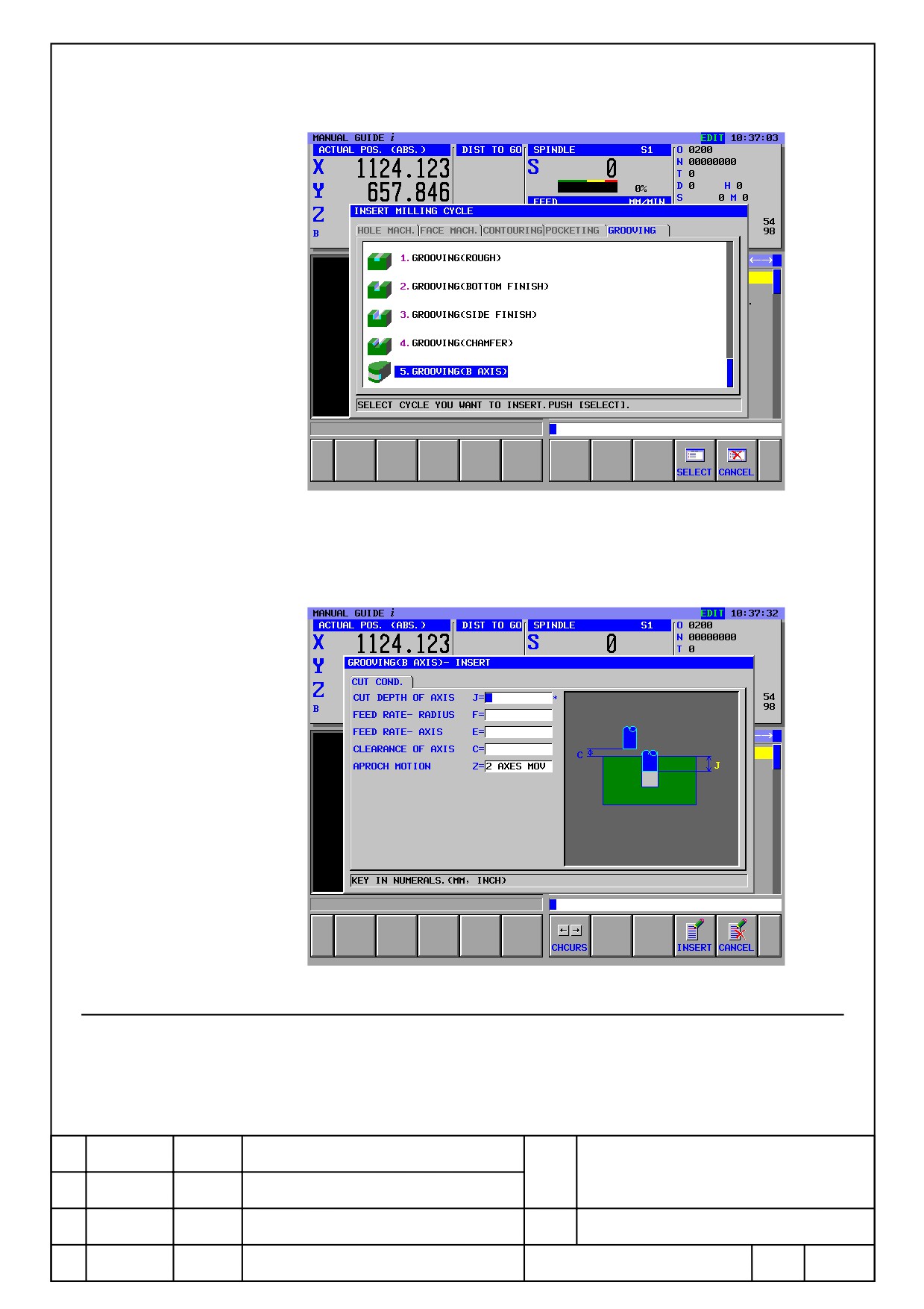
Then, select the menu to display data entry screen of grooving (B axis) as
below figure. Input the data by following the entry items, and press
[INSERT] soft key to create a program.
24.2.4
Figure Block Entry
Press [FIGURE] soft key, the menu screen for selecting milling figure is
opened. And select tab “GROOVE FIG”, the menus of the groove figure on
YB plane are displayed.
FANUC MANUAL GUIDE i
Name
(Series16i/18i/21i-MB/TB)
OPERATOR’S MANUAL
Draw.
B-63874EN/05-1
Ed.
Date
Design
Description
Page
69/100
FANUC LTD.
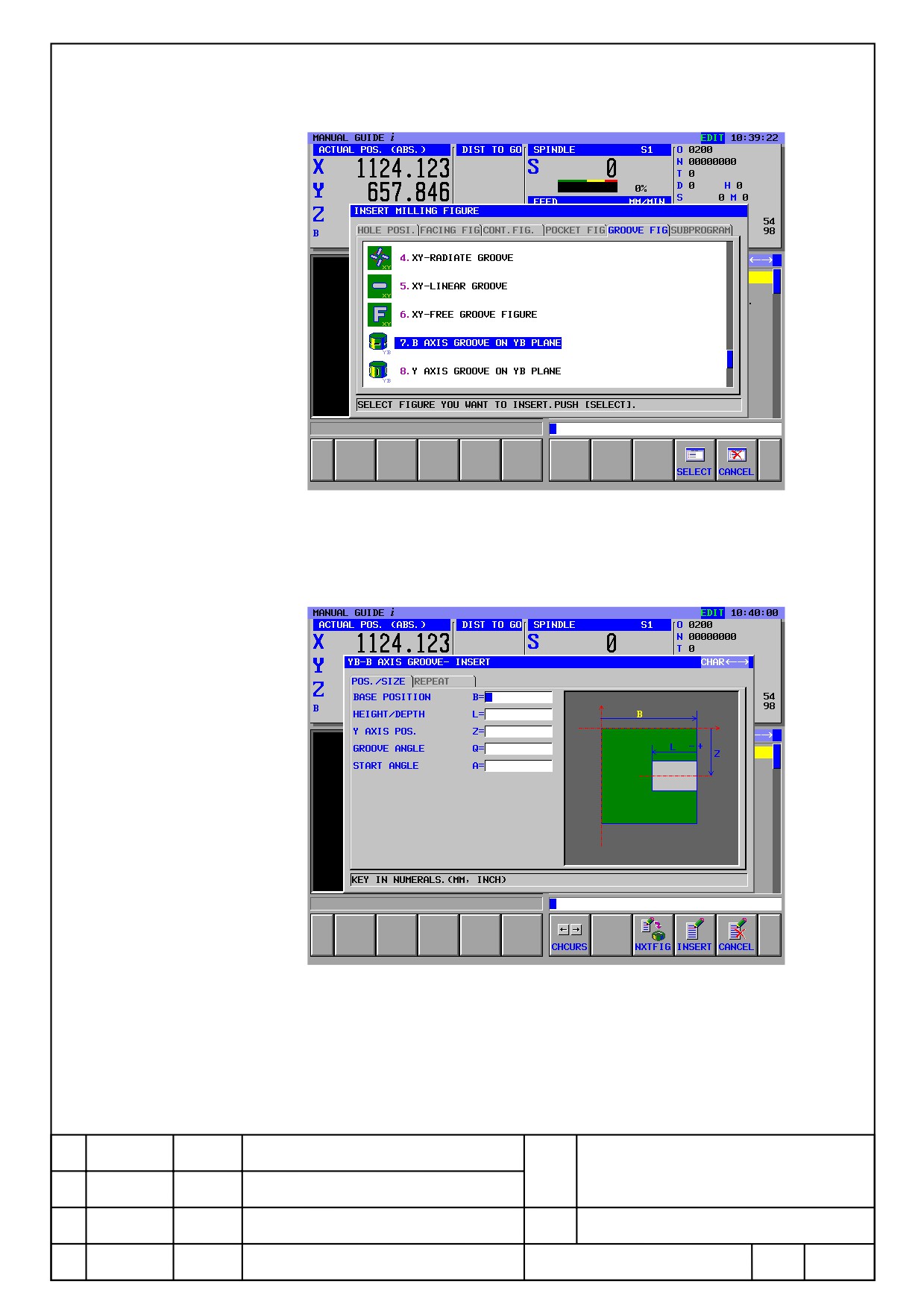
Select the menu to display the data entry screen of YB cylindrical face as
below figure. Input the data by following the entry items, and press
[INSERT] soft key to create a program.
Press [FIGURE] soft key, the screen for selecting milling figure is opened.
And select [HOLE POSI.] tab, the menus of hole figure on YB plane are
displayed as below figure.
FANUC MANUAL GUIDE i
Name
(Series16i/18i/21i-MB/TB)
OPERATOR’S MANUAL
Draw.
B-63874EN/05-1
Ed.
Date
Design
Description
Page
70/100
FANUC LTD.
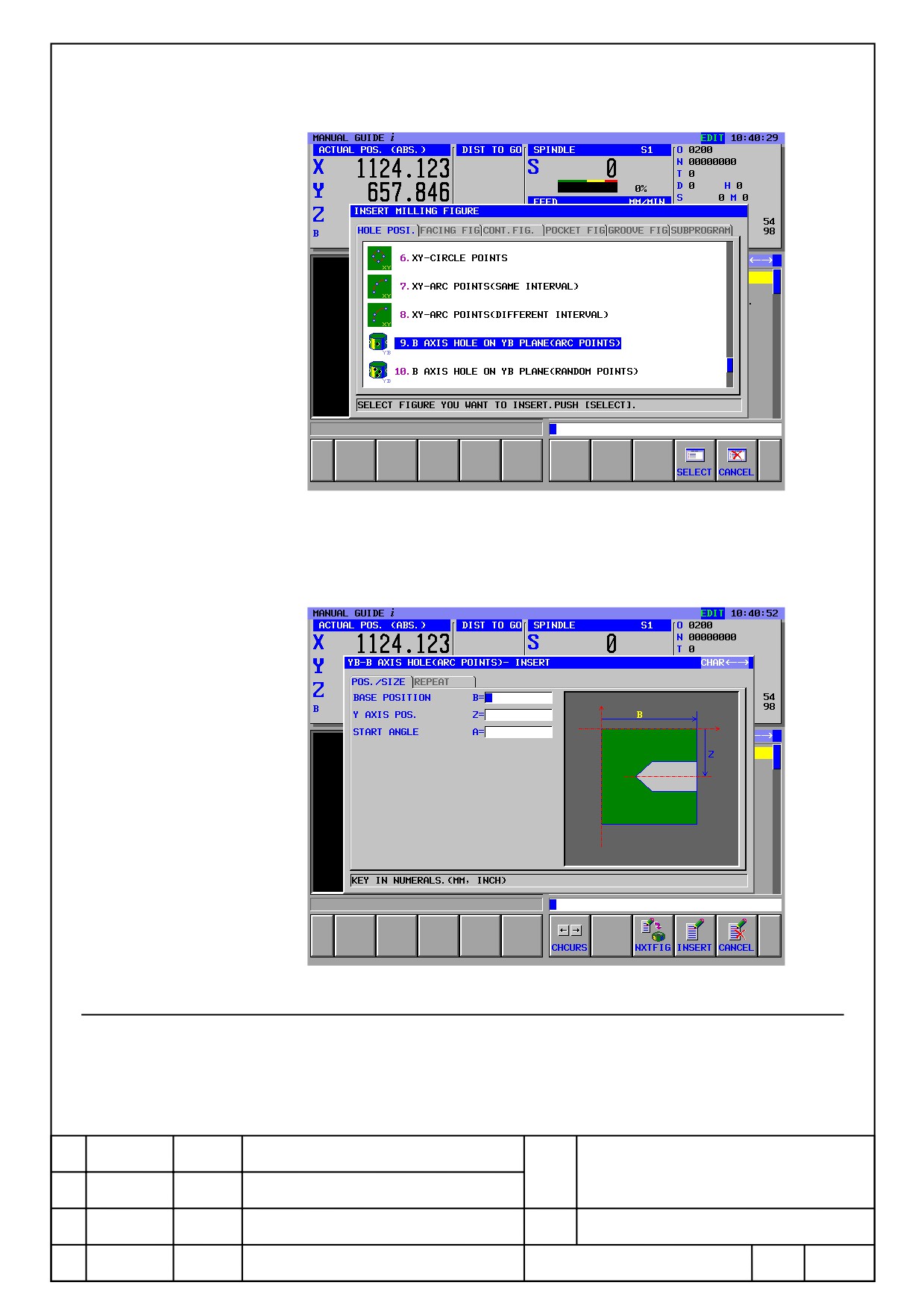
Select the menu to display the figure data entry screen of YB cylinder face
as below figure. Input the data by following the entry items, and press
[INSERT] soft key to create a program.
24.2.5
Blank Data
The following G code is added as the Blank data.
(1) Cylinder Blank Figure (Round Y axis) : G1756
(2) Hollow Cylinder Blank Figure (Round Y axis) : G1757
(3) Prism Blank Figure (Round Y axis) : G1758
FANUC MANUAL GUIDE i
Name
(Series16i/18i/21i-MB/TB)
OPERATOR’S MANUAL
Draw.
B-63874EN/05-1
Ed.
Date
Design
Description
Page
71/100
FANUC LTD.
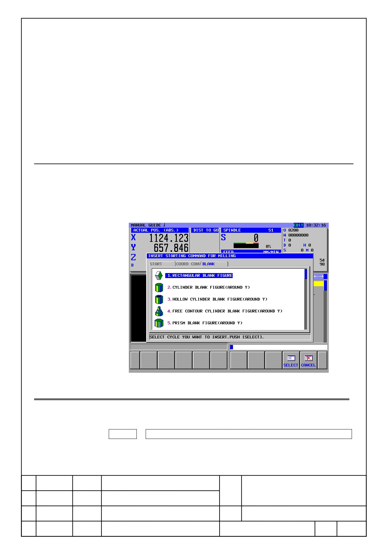
(4) Hollow Prism Blank Figure (Round Y axis) : G1759
(5) Free Figure Cylinder Blank Figure (Round Y axis)
Start Point (Round Y axis) : G1780
Line (Round Y axis) : G1781
Arc (CW) (Round Y axis) : G1782
Arc (CCW) (Round Y axis) : G1783
Face Removal (Round Y axis) : G1784
Corner R (Round Y axis) : G1785
End Point (Round Y axis) : G1786
24.2.6
Blank Data Entry
The menus of Blank Figure round Y axis are displayed for cylinder blank
figure, hollow cylinder blank figure and free figure cylinder blank figure.
By selecting the menu and enter the data according to a guidance message,
define the blank figure.
24.3. Parameters
This function is available by setting the below parameters.
14717
Axis Number of B Axis
Data Range :
0 ~ Number of control axis
FANUC MANUAL GUIDE i
Name
(Series16i/18i/21i-MB/TB)
OPERATOR’S MANUAL
Draw.
B-63874EN/05-1
Ed.
Date
Design
Description
Page
72/100
FANUC LTD.
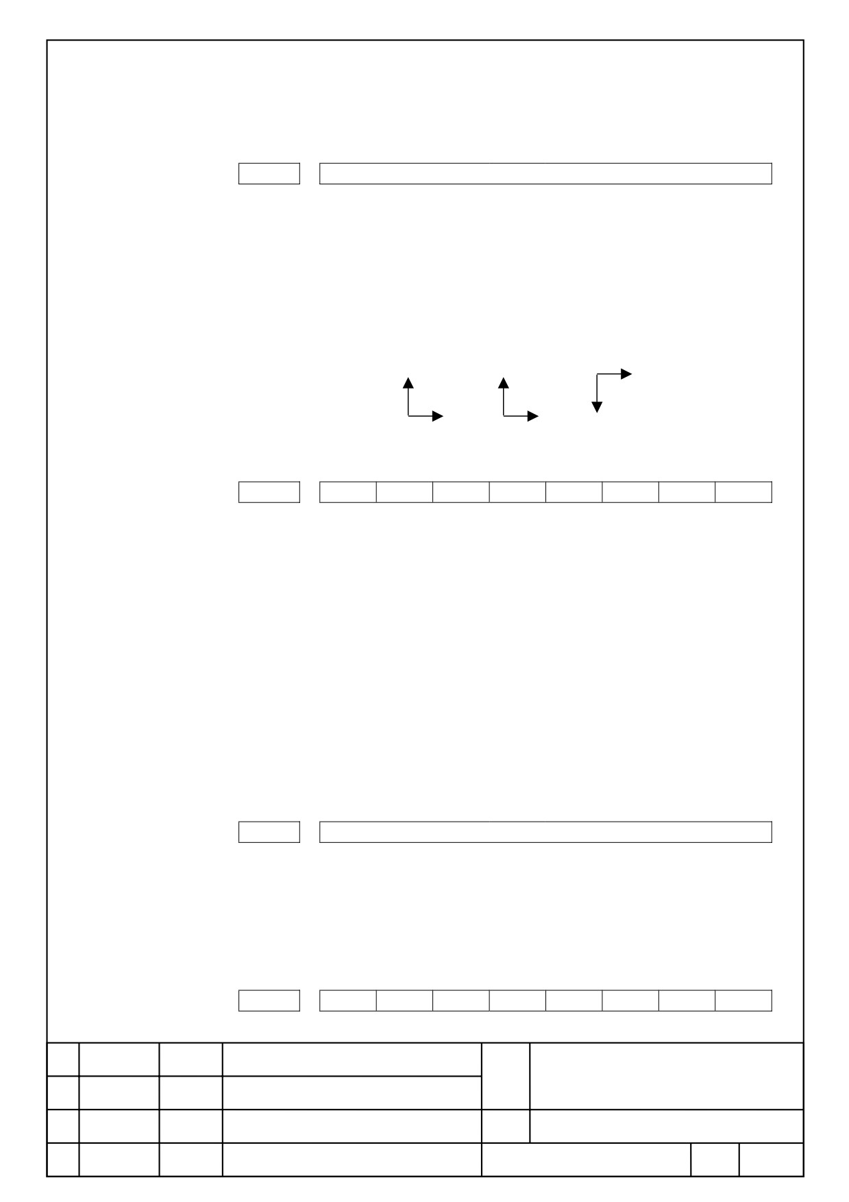
14842
Drawing coordination on the blank figure screen of cylindrical free
figure.
=0 Same as the data 6
=1 Plane figure Horizontal axis =+Y, Vertical axis =+Z
=5 Plane figure Horizontal =+Y, Vertical axis =+Z
=6 Plane figure Horizontal =+Y, Vertical axis =-Z
Z
Y
Z
Y
Z
Y
1
5
6
#7
#6
#5
#4
#3
#2
#1
#0
27314
#1
#0
Whether to display a blank figure of Y-axis direction is depend on
the following parameter settings.
#0
0 : Display a blank figure of Z-axis direction at definition screen of
blank figure.
1 : Undisplay a blank figure of Z-axis direction at definition screen
of blank figure.
#1
0 : Undisplay a blank figure of Y-axis direction at definition
screen of blank figure.
1 : Display a blank figure of Y-axis direction at definition screen of
blank figure.
* Because rectangular blank figure is common with each axis rotation, it
displays always with no relation to the above-mentioned parameter.
27334
Center axis of work rotation for rectangular blank figure at
machining simulation.
=0 Round Z-axis
=1 Round Y-axis
#7
#6
#5
#4
#3
#2
#1
#0
27003
#3
#2
#1
#0
FANUC MANUAL GUIDE i
Name
(Series16i/18i/21i-MB/TB)
OPERATOR’S MANUAL
Draw.
B-63874EN/05-1
Ed.
Date
Design
Description
Page
73/100
FANUC LTD.
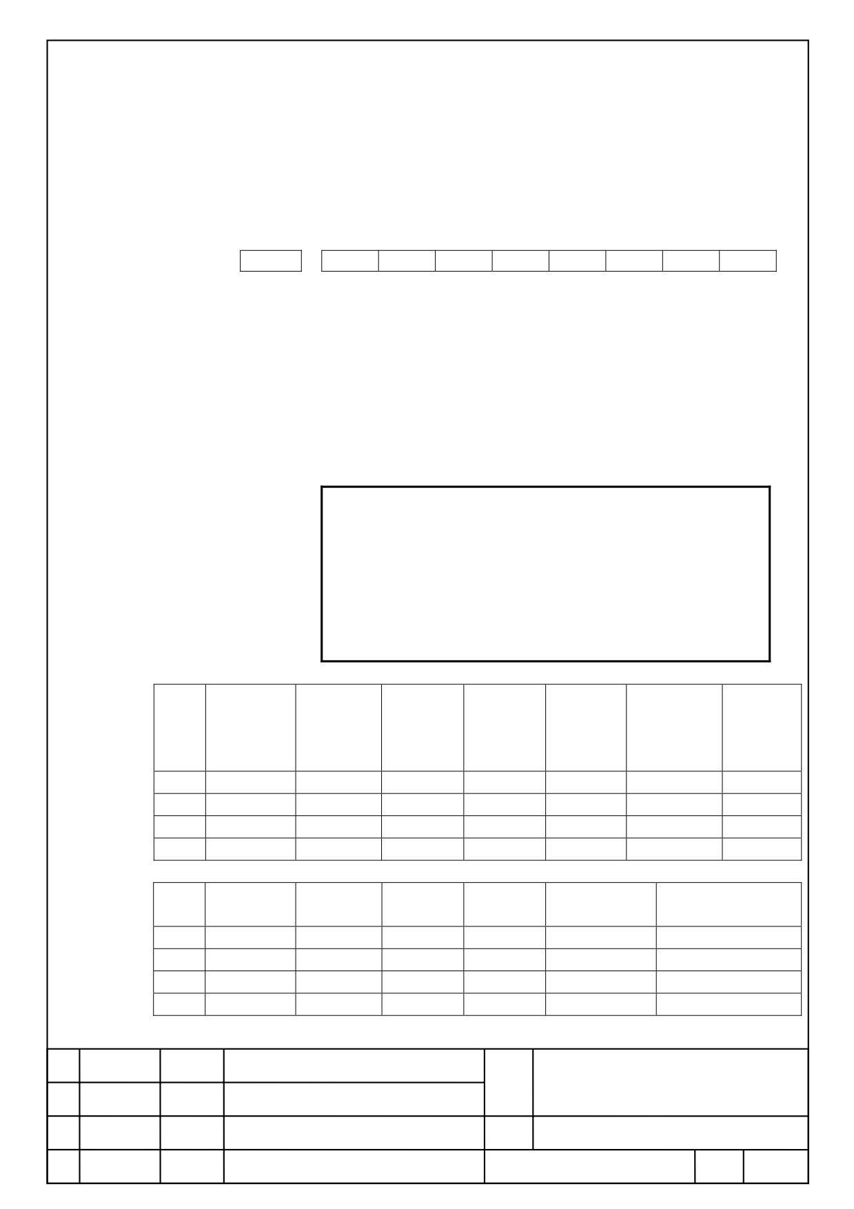
27003#0=0, 27003#1=0, 27003#2=0, 27003#3=1,
Axis structure of machining center is X/Y/Z/B.
Displaying a menu of blank round Y-axis direction in blank
definition.
#7
#6
#5
#4
#3
#2
#1
#0
27004
#3
#2
#1
#0
P27004#0=1, 27004#1=0, 27004#2=0, 27004#3=1,
The following menus are displayed.
Grooving : Grooving (B axis) --- G1054
Hole Figure : B axis Hole figure (on arc) YB Plane --- G1777
B axis Hole figure (random points) YB Plane --- G1778
Groove Figure :B axis groove figure of YB Plane --- G1775
Y axis groove figure of YB Plane --- G1776
NOTE
1 After set the parameter No.27003, [F] key must be pressed at a
screen of NOW LOADING after power has been restored. Required
parameter is automatically set. (When parameter is set
automatically, a message ”NOW SETTING PARAMETERS” is
displayed at bottom left corner.)
2 By set the No.27003, the following parameter related to display are
automatically set.
No.27000#6
No.27000#1
No.27000#4
No.27100#4
No.27001#0,#1
No.14702#1
Convert
No.27060#1
Change Hole
Face
Face
Rotation Axis
Select Spindle
Coordinatio
PR1
Machining
Position-M
Position -T
Name
n
0
0
0
0
1
0
1
ML0
0
0
0
0
0
0
1
ML1
0
0
0
0
0
0
1
ML2
0
0
0
0
0
0
1
ML3
No.27004#0
No.27004#1
No.27004#2
No.27004#3
No.27314#0,#1
No.27334
Menu 1
Menu 2
OP 1
OP 2
Set Blank Figure
Set Rectangular Blank
ML0
1
0
0
0
0
0
ML1
0
0
0
0
0
0
ML2
1
0
1
0
0
0
ML3
1
0
0
1
1
1
FANUC MANUAL GUIDE i
Name
(Series16i/18i/21i-MB/TB)
OPERATOR’S MANUAL
Draw.
B-63874EN/05-1
Ed.
Date
Design
Description
Page
74/100
FANUC LTD.
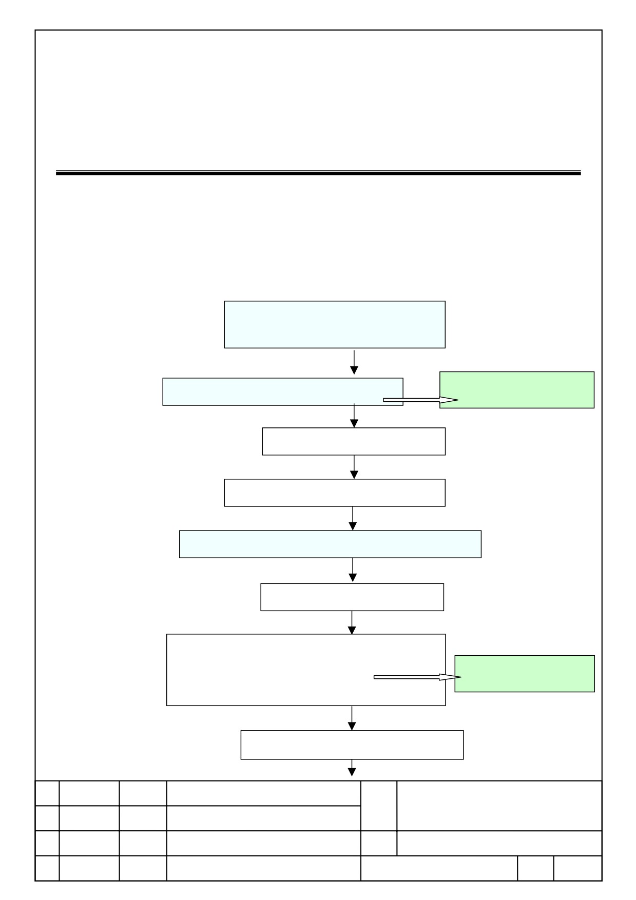
25
Counter Tapping Cycle
At tapping cycle for turning (work rotation, tapping by rotating tool),
counter tapping can be operated. This function is available by set the
parameter 27195<#1:TRV>, and <#0:WRV> to 1.
When this function is available, output [M-code to notice tapping / counter
tapping], counter rotation of spindle is controlled by PMC with the M-code,
as below.
M code command before Normal Rotation/
counter rotation tapping
(Output float tap)
Reverse the rotation by
Spindle Normal Rotation Command (Float Tap)
PMC side, actually
Move to holing position
Move to Approach point(R point)
(M Code before Normal Rotate/Counter Rotate Tapping)
(Output rigid tap)
(Output a Rigid tap, Output S
Tapping (G84/88 Command)
(1) Spindle Normal Rotation(Rigid)
Reverse the rotation by
(2) Counter rotate at bottom hole
PMC side, actually
(3) Return to R point, and Normal Rotate. Stop at Rigid
(Move to next holing position , Holing)
FANUC MANUAL GUIDE i
Name
(Series16i/18i/21i-MB/TB)
OPERATOR’S MANUAL
Draw.
B-63874EN/05-1
Ed.
Date
Design
Description
Page
75/100
FANUC LTD.
Finishing of Holing(G80)
Tapping cycle G 84 for turning, M04 is always output when spindle rotation
command is weather normal rotation or counter rotation tapping. When tool
is returned to R point, M 03 is output.(At rigid tapping, it output as M03
after moving to R point.→M05 at the bottom →M04,→M05 after
returning.)
Because same M code is output by NC at normal rotation tapping or counter
rotation tapping, actual spindle rotation is reversed at PMC side when
operating counter tapping.
To reverse the spindle rotation by PMC side, [M code to notice Normal
Rotation / Counter Rotation] is used to operate.
On PMC, provide a sign to reverse the rotation of spindle rotation command
after this M code, and reverse the spindle rotation command by this sign.
The sign newly provided is operate cancellation of this sign by PMC ladder
side, such as canceling at TAP signal (F0002<#5:TAP>).
25.1.
Specify Normal Tapping / Counter Tapping
Parameter No.27195<#1:TRV>, <#0:WRV> are set to 1, [Machining Type
W] is displayed at deleting condition menu of tapping.
When a cursor is placed to [Machining Type W] , soft key [Normal] or
[Counter Tap] is displayed. Select either one.
Specified upper machining type is programmed as below.
G1102 W1/W2 ……..;
(Work Rotation)
W1: Normal W2: Counter Tap
G1112 W1/W2 ……..;
(Tool Rotation)
W1: Normal W2: Counter Tap
25.2.
Machining Operation
25.2.1
Float Tapping by work rotation
When this function is available, operate G1102 to operate a command as
followings. (G code Type A)
Ordered by parameter
(*1)
:
M(nth spindle Normal / Counter tapping command);
Ordered by parameter
(*2)
M(nth spindle Normal tapping command);
G0X0;
---- Move to a hole position
FANUC MANUAL GUIDE i
Name
(Series16i/18i/21i-MB/TB)
OPERATOR’S MANUAL
Draw.
B-63874EN/05-1
Ed.
Date
Design
Description
Page
76/100
FANUC LTD.
Z___ _;
---- Move to approach point
G84 Z______R______P_____F_____;
---- Tapping Command
G80;
:
When a parameter of counter tapping command M code is unset at
operating a counter tapping command, P/S alarm [3017 NO M-CODE
BEFORE TAP CYCL] is occurred.
When a parameter of normal tapping command M code is unset at
operating a normal tapping command, no data is output with off alarm.
(*1) Parameter No.27196 ~ 27201
(*2) Parameter No.27202,27204,27206
Please refer the chapter of parameter description for details for the
parameters listed above.
25.2.2
Rigid Tapping by work rotation
When this function is available, operate G1102 to operate a command as
followings.(G code Type A)
:
G0X0;
---- Move to a hole position
Ordered by parameter
(*1)
Z____;
---- Move to approach point
M(nth spindle Normal/Counter tapping command);
M__S_____;
---- Command of Rigid tapping mode
G84 Z______R______P_____F_____; ---- Command of Rigid tapping mode
G80;
:
When a parameter of counter tapping command M code is unset at
operating a counter tapping command, P/S alarm [3017 NO M-CODE
BEFORE TAP CYCL] is occurred.
When a parameter of normal tapping command M code is unset at
operating a normal tapping command, no data is output with off alarm.
(*1) Parameter No.27196 ~ 27201
Please refer the chapter of parameter description for details for the
parameters listed above.
FANUC MANUAL GUIDE i
Name
(Series16i/18i/21i-MB/TB)
OPERATOR’S MANUAL
Draw.
B-63874EN/05-1
Ed.
Date
Design
Description
Page
77/100
FANUC LTD.
25.2.3
Selecting Spindle
As explaining below, M code before tapping or M code for spindle normal
rotation are required to output by following a spindle currently selected.
Specify a selecting spindle number from a screen as below.
・When this function is available with a spindle is1(parameter
No.14702#1=0), [spindle number Q] is displayed.
Spindle Number Q
Spindle1
・When a cursor is placed at [Spindle Number Q], soft key [Spindle 1] and
[Spindle 2] are displayed. Spindle number selected at [Spindle
number Q] is displayed by pressing soft key.
・Specified upper spindle number is programmed a below.
G1102 W1……Qn…;(Work Rotation Tap)
Qn = Q1:Select a Spindle 1, Q2: Select a Spindle 2
NOTE) Operating G 1102 with this function is available, a movement
when returned value Q of spindle number is unset is as follows.
・When using more than 2 spindle(parameter No14702#1=1), it alarm out
as [WRONG SPINDLE NUMBER].
・When using spindle is one(parameter No. 14702#1=0), it operates as
spindle number 1(Refer a parameter for spindle number 1, for parameter
set as referring spindle parameter)
25.2.4
Float Tapping by Tool Rotation
Operating G1112 when this function is available, the following command is
operated.(Listed as G code Type A)
:
G0
;
---- Move to 1st hole position
Z____;
---- Move to approach point
Ordered by parameter
(*1)
M(For Each Turrets Pre command to rotating tool /
command before counter tapping);
Ordered by parameter
(*2)
M(For Each Turrets Pre command to rotating tool);
G84/88 Z______R______P_____F_____;
---- Tapping Command
____; ---- Move to 2nd hole position, and holing
:
G80 ;
:
FANUC MANUAL GUIDE i
Name
(Series16i/18i/21i-MB/TB)
OPERATOR’S MANUAL
Draw.
B-63874EN/05-1
Ed.
Date
Design
Description
Page
78/100
FANUC LTD.
When a parameter of M code command before a counter tapping is unset,
P/S alarm occur.[3017 NO M-CODE BEFORE TAP CYCL]
When a parameter of normal tapping command M code is unset at
operating a normal tapping command, no data is output with off alarm.
(*1) Parameter No.27208,27209
(*2) Parameter No.27210
Please refer the chapter of parameter description for details for the
parameters listed above.
25.2.5
Rigid Tapping by Tool Rotation
Operating G1112 when this function is available, the following command is
operated.(Listed as G code Type A)
:
G0____;
---- Move to 1st hole position
Z____;
---- Move to approach point
Ordered by parameter
(*1)
M(For Each Turrets Pre command to rotating tool /
command before counter tapping);
M__ S_____;
---- Rigid Tapping mode Command
G84/88 Z______R______P_____F_____;
---- Rigid Tapping Command
____; ---- Move to 2nd hole position, and holing
:
G80 ;
:
When a parameter of counter tapping command M code is unset at
operating a counter tapping command, P/S alarm[3017 NO M-CODE
BEFORE TAP CYCL]is occurred.
When a parameter of normal tapping command M code is unset at
operating a normal tapping command, no data is output with off alarm.
(*1) Parameter No.27208,27209
Please refer the chapter of parameter description for details for the
parameters listed above.
FANUC MANUAL GUIDE i
Name
(Series16i/18i/21i-MB/TB)
OPERATOR’S MANUAL
Draw.
B-63874EN/05-1
Ed.
Date
Design
Description
Page
79/100
FANUC LTD.
25.3.
Parameters
About the details of the parameters for this function, refer to the chapter
“30 Parameters”. And there is the following CNC Parameters related to this
function.
#7
#6
#5
#4
#3
#2
#1
#0
5200
G84
Command method of rigid tapping.
G84
Command method of rigid tapping.
0:command M code of rigid tapping mode command preceding
G84command.
1:Not command M code of rigid tapping mode command
(G84command)
(It cannot command G84 for float tapping as G code.)
5210
M code command in rigid tapping mode
M code command in rigid tapping mode
Setting Range
0~255
M29 is output when 0 is set
When M code over 256 is needed to use, set a parameter No5212.
5212
M code command in rigid tapping mode
M code command in rigid tapping mode
Setting Range
0~255
When M code over 256 is needed to use, set this parameter.
FANUC MANUAL GUIDE i
Name
(Series16i/18i/21i-MB/TB)
OPERATOR’S MANUAL
Draw.
B-63874EN/05-1
Ed.
Date
Design
Description
Page
80/100
FANUC LTD.
26
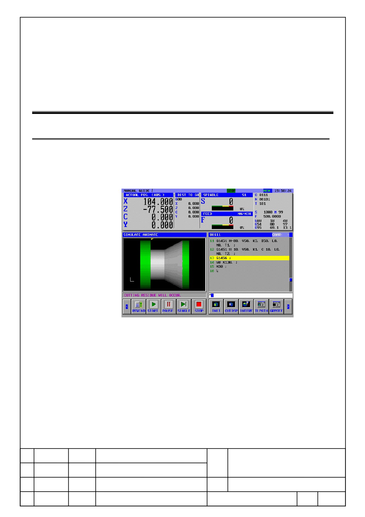
A warning message when a residual cutting
part remains
26.1. Details
When a residual cutting part remains in turning cycle, a warning
message ”CUTTING RESIDUE WILL OCCUR” is displayed. And, it is not
necessary to set any parameter for this function.
FANUC MANUAL GUIDE i
Name
(Series16i/18i/21i-MB/TB)
OPERATOR’S MANUAL
Draw.
B-63874EN/05-1
Ed.
Date
Design
Description
Page
81/100
FANUC LTD.
27
Simultaneous Facing at Turning Cycle
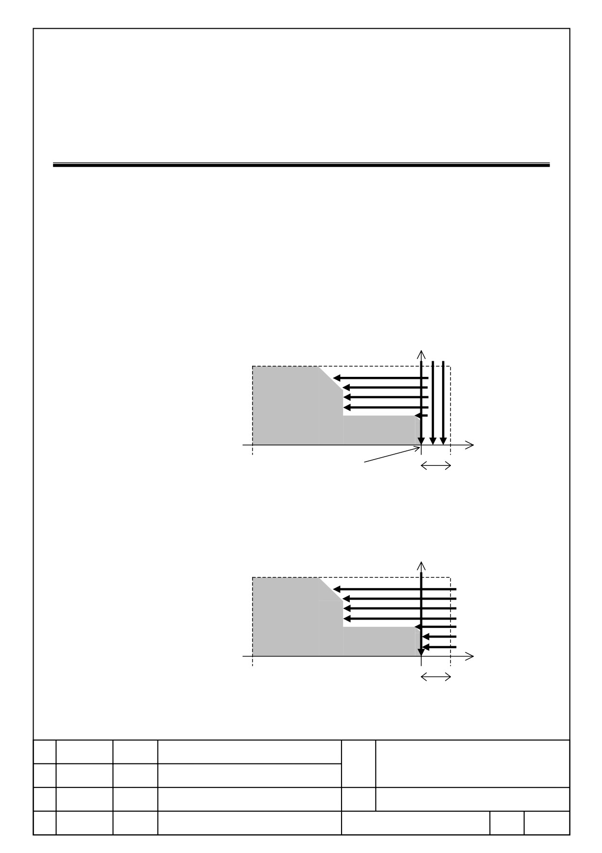
For blank outer or inner machining, facing can be operated at the same
process (Simultaneous Facing) as follows.
This function is available when a parameter No. 27120#2 = 1.
When this function is available, by selecting the turning (outer rough) or
the turning (inner rough) menu, [Facing] tab is displayed and possible to
specify a simultaneous facing of turning.
This function is available only at turning rough.
< Roughing with using a simultaneous facing of turning >
X
Z
Face center
Face removal
(Operating outer machining after cutting the facing removal part)
< Roughing without using a simultaneous facing of turning >
X
Z
Face removal
FANUC MANUAL GUIDE i
Name
(Series16i/18i/21i-MB/TB)
OPERATOR’S MANUAL
Draw.
B-63874EN/05-1
Ed.
Date
Design
Description
Page
82/100
FANUC LTD.
27.1.
Operations
27.1.1
Specify the Simultaneous Facing
When this function is available, [Facing ] tab is displayed at [Turning
(Outer Rough)] or [Turning (Inner Rough)].
Select [Facing] tab to display the following items.
・Facing availability N
Selection of facing availability is selected by the soft key [Facing] and
[None] displayed at this tab.
On outer rough, the following entry items are displayed by selecting
[Facing]. On inner rough , it is not displayed.
・Face Removal
I
Cut depth and feed rate at facing is decided as following.
Facing cut depth is automatically set by face removal amount and
outer/inner cut depth amount. Please refer a chapter on machining
operations for in details.
Facing cut feed rate is used cut feed rate of outer/inner cut. Please refer a
chapter on machining operations for in details.
27.1.2
Settings of Face Removal
Face removal amount is used either [Face Removal I] that is entered on the
screen, or face removal set by a parts figure and a blank figure.
However, a face removal cannot specify at inner rough and it should specify
a blank figure at face removal parts.
When any removal amount isn’t entered, simultaneous facing cannot
operated.
・When face removal I is not entered, face removal amount set by parts
figure, blank figure is used.
・When face removal I is entered, a larger amount of each removal amount
is used.
Settings of [Face Removal]
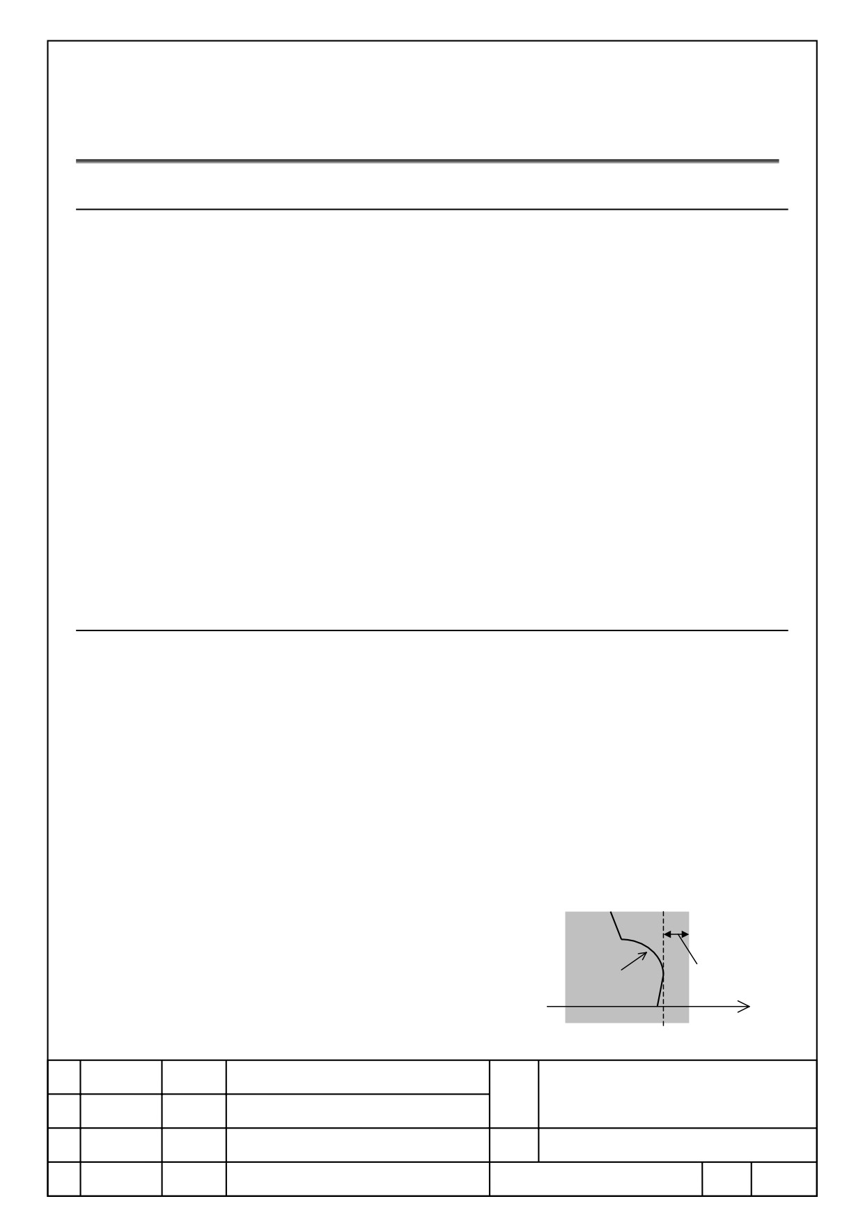
<When cut direction is -Z>
Specify the amount from parts
Face Removal I
Face(Max z point of parts
Parts Figure
figure) as right figure.
+Z
<When cut direction is +Z>
Parts Face
FANUC MANUAL GUIDE i
Name
(Series16i/18i/21i-MB/TB)
OPERATOR’S MANUAL
Draw.
B-63874EN/05-1
Ed.
Date
Design
Description
Page
83/100
FANUC LTD.
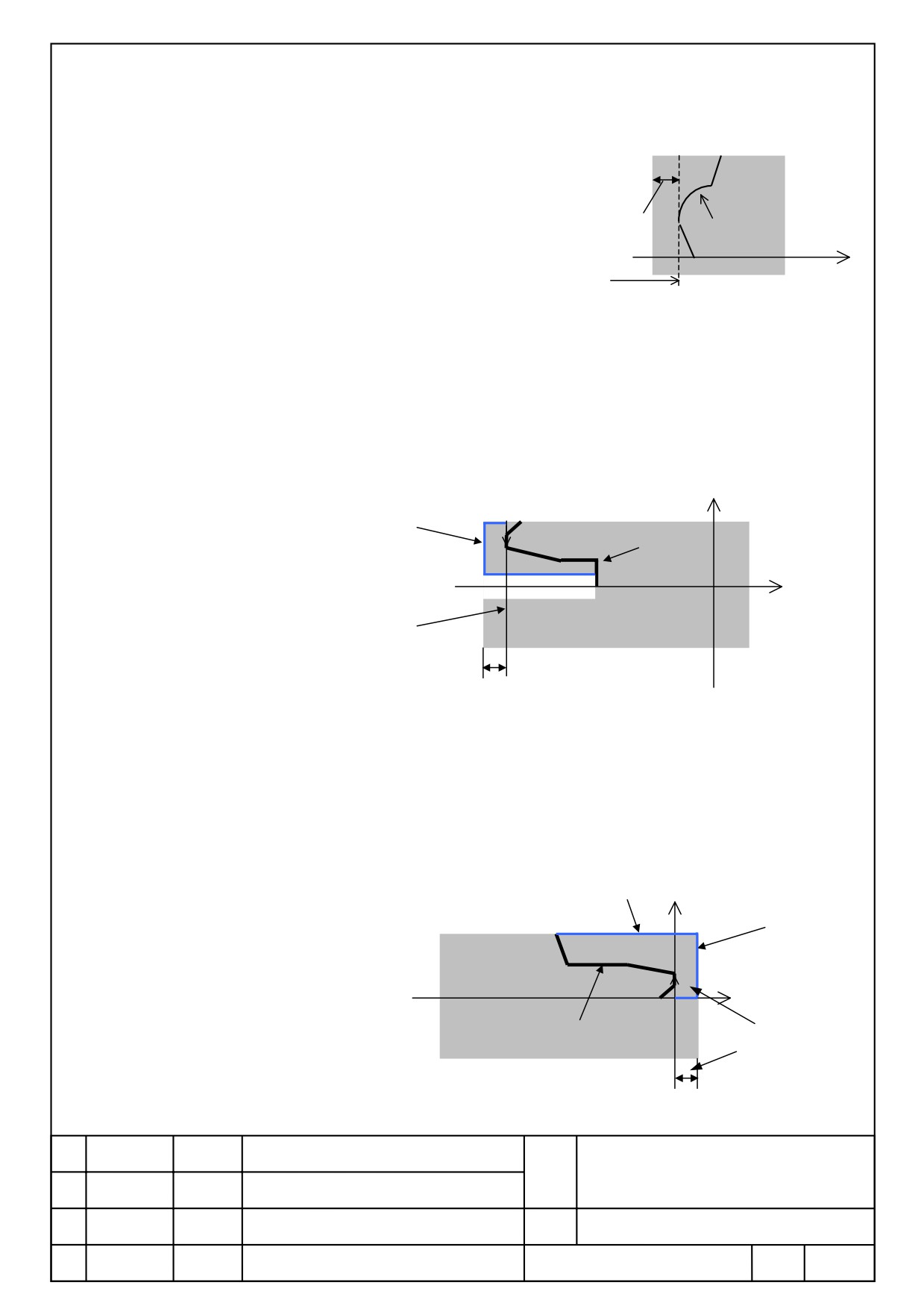
Specify the amount from parts
Face(Minimum z point of parts
figure) as right figure.
Face Removal I
Parts Figure
+Z
Parts Face
Face Removal set from Parts Figure, Blank Figure
<When cut direction is -Z>
As the below figure, either at outer or inner, the amount from parts
face(Maximum Z of parts figure) to
blank figure(Maximum Z of blank figure) is the face
removal amount.
+X
<Inner Machining>
Blank Face
(Blank Figure)
Parts Figure
+Z
Parts Face
Face Removal
<When cut direction is -Z>
As the below figure, either at outer or inner, the amount from parts
face(Minimum Z of parts figure) to
blank figure(Minimum Z of blank figure) is
the face removal amount.
< Outer Machining > Blank Figure
+X
Blank Face
+Z
Parts Face
Parts
Face Removal
Figure
FANUC MANUAL GUIDE i
Name
(Series16i/18i/21i-MB/TB)
OPERATOR’S MANUAL
Draw.
B-63874EN/05-1
Ed.
Date
Design
Description
Page
84/100
FANUC LTD.
Note: Cut direction of Facing is follow the cut direction of outer/inner
machining.
27.2. Machining Operations
27.2.1
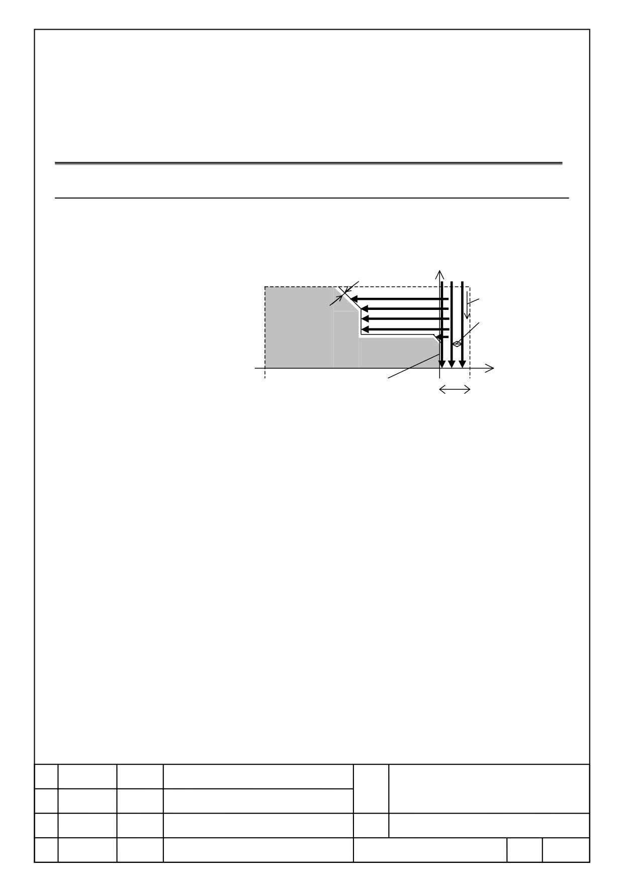
Outer Facing Rough
At outer facing rough, as the figure below cut off the face part first(①), then
outer machining (②) is operated. Cut direction of face part is always X
minus direction as the figure below.
①
②
Face Cut Feed Rate
Finish
Amoun
Face Cut Depth
Z
1st Figure Part
Face Removal
Face cut depth is automatically set by face removal and outer/inner cut
depth as follow.
(Face Removal)
------------------------------------- ==( round up after the decimal point)=>Number
(Outer or Inner Cut Depth)
of Cutting
N
(Face Removal)
-------------------------
==Face Cut Depth d’
(N)
Calculated face cut depth d +override, recalculate the face cut depth.
(Face Removal Amount)
------------------------------------
=(round up after the decimal point)=>Number
(d’)x Override
of Cutting N’
(Face Removal)
------------------------------
==
Face Cut Depth d
(N’)
Specify the override by parameter 27131. When a set value is 0, the
override is 100%
Face cut feed rate is the amount override(%) is added to outer/inner cut
feedrate.
That override is specified by a parameter 27132, and a set value is 0,the
override is 100%.
FANUC MANUAL GUIDE i
Name
(Series16i/18i/21i-MB/TB)
OPERATOR’S MANUAL
Draw.
B-63874EN/05-1
Ed.
Date
Design
Description
Page
85/100
FANUC LTD.