FANUC MANUAL GUIDE i. OPERATOR’S MANUAL - page 31
9
Simultaneous Delete of Multiple Programs
Select a several programs, and it is possible to delete at once. Using the
three of individual selection, range selection, and all selection to select the
programs to delete.
It is also possible to remove from the selection individually using unselect.
For these selected multiple programs, deleting is performed.
NOTE
1 Conventionally, deleting all registered program in a folder is
performed by pressing [ALLDEL] soft key. That conventional function
is included to this function. All delete operation is converted to the
method of deleting after selecting the all programs with this function
of multi programs simultaneous deletion. Therefore, unnecessary
[ALLDEL] soft key is deleted, and newly added the [MLTDEL] soft
key to operate this function for same position.
9.1.
Details
NEWPRG
O-LIST
SRCH↑
SRCH↓
O SRCH
COPY
CUT
DELETE
KEYPST
PAST
Press [O-List] to display a window to open program.
FANUC MANUAL GUIDE i
Name
(Series16i/18i/21i-MB/TB)
OPERATOR’S MANUAL
Draw.
B-63874EN/05-1
Ed.
Date
Design
Description
Page
26/100
FANUC LTD.
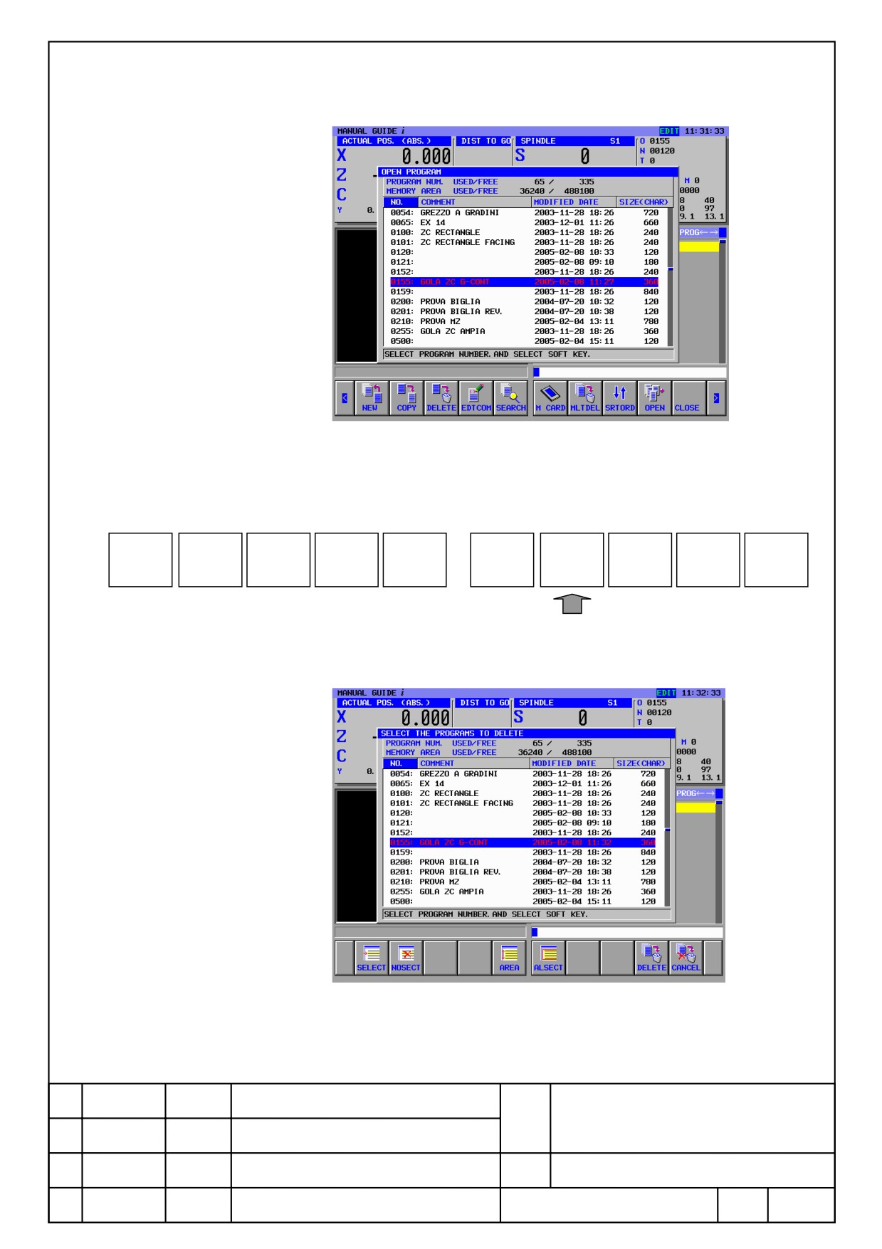
In this event, below soft keys are displayed.
A position [ALLDEL] were displayed in conventional version, [MULDEL] is
displayed.
NEW
COPY
DELETE
EDTCOM
SEARCH
M CARD
MLTDEL
SRTORD
OPEN
CLOSE
At a window to open program, press [MLTDEL] to open a window to select
the programs to delete.
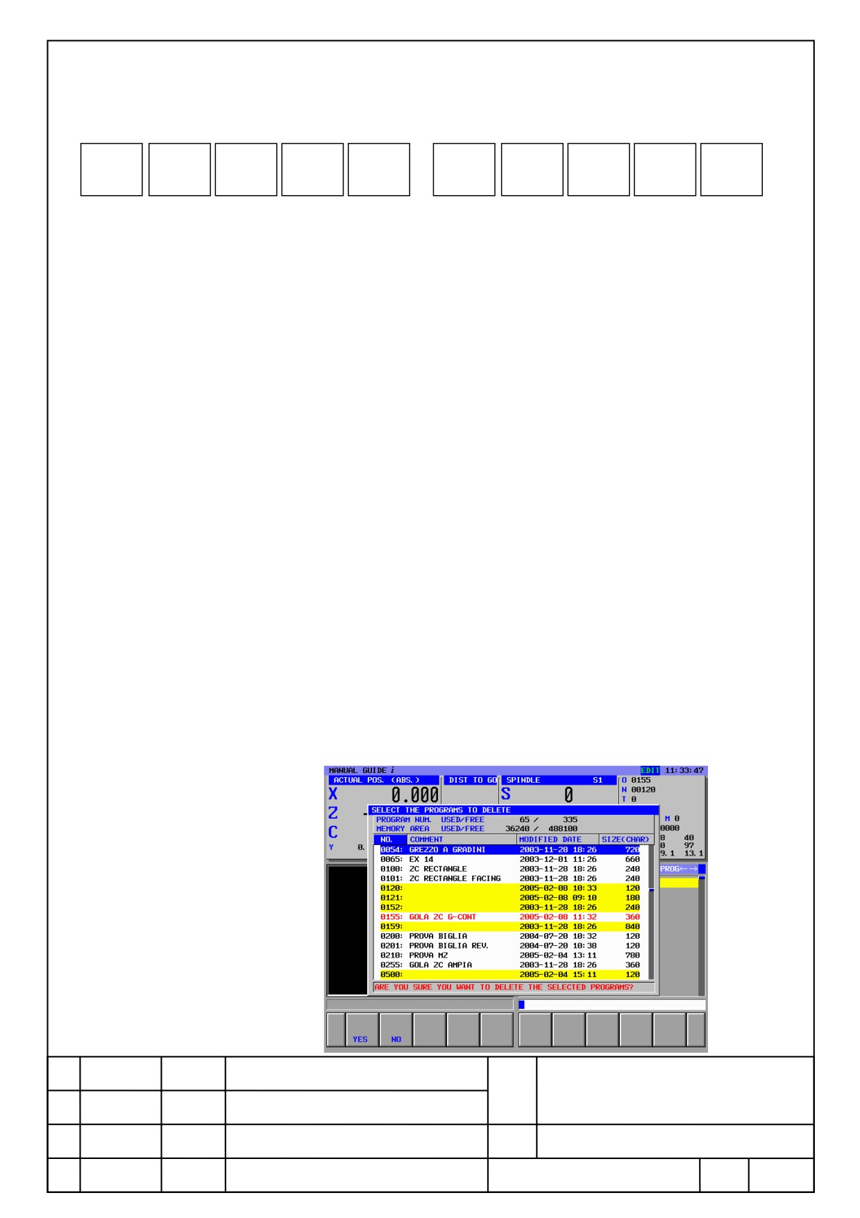
In this event, below soft keys are displayed.
FANUC MANUAL GUIDE i
Name
(Series16i/18i/21i-MB/TB)
OPERATOR’S MANUAL
Draw.
B-63874EN/05-1
Ed.
Date
Design
Description
Page
27/100
FANUC LTD.
SELECT
NOSECT
AREA
ALSECT
DELETE
CANCEL
[SELECT] Use to select a program individually. Move a cursor to a
program selected, and press [SELECT]. Background color of
selected program is changed to yellow.
[NOSECT] Individually remove from a selection. Move to a cursor to a
program to unselect, and press [NOSECT]. Background color of
unselected program is changed back from yellow to white.
[AREA]
Use to select a range. Move a cursor to a top of selected
program, and press [AREA]. Move a cursor to the end program
to be selected. At this time, background color of specified area
changed to purple. Then, press
[SELECT] to determine.
Background color of selected program is changed from purple to
yellow.
[ALSECT] Use to select all programs. All programs in a folder are selected,
and background color of these programs is changed to yellow.
[DELETE] Delete the selected programs.
[CANCEL] All programs in a folder are unselected, and background color
of program change back from yellow to white.
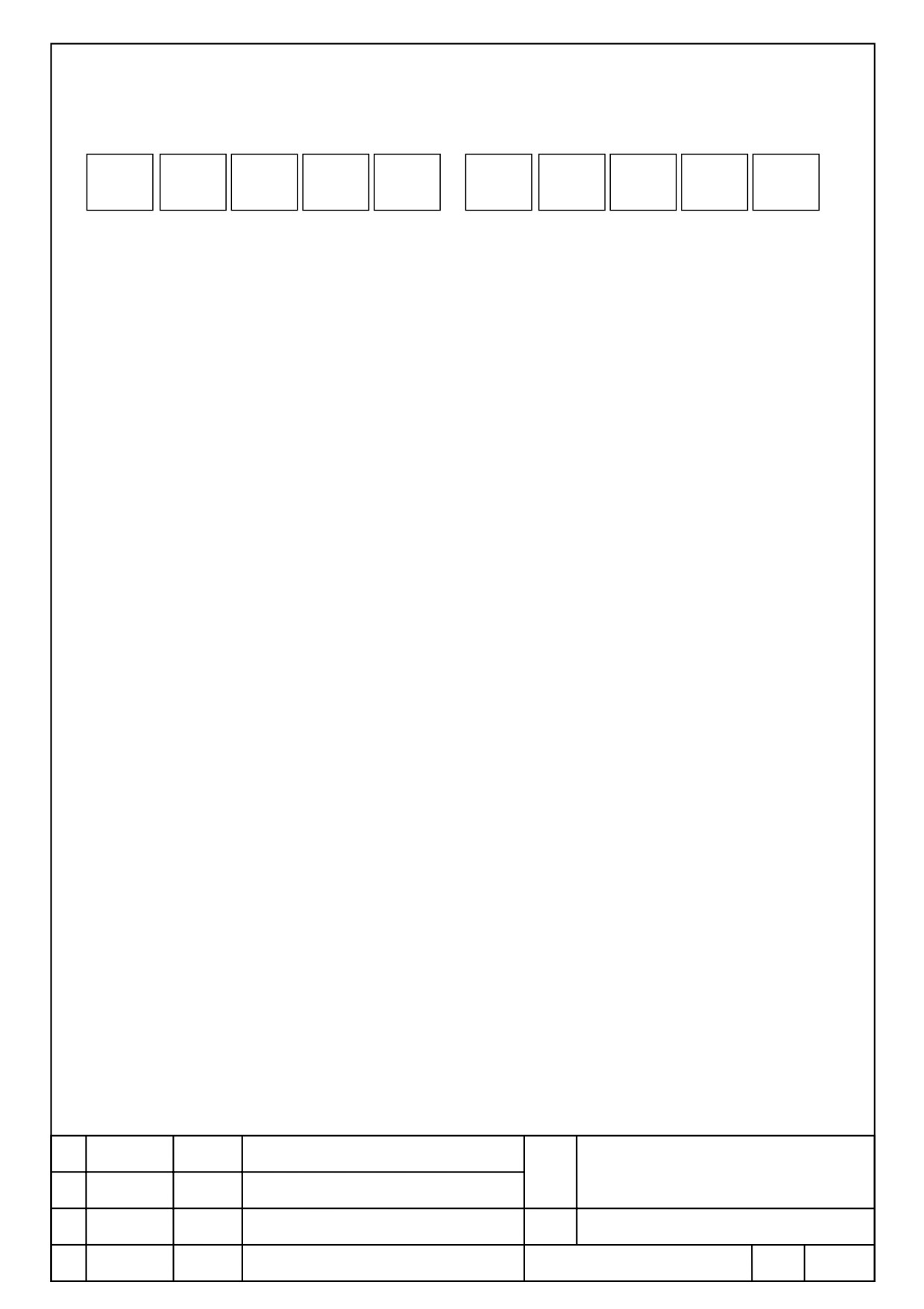
By press [DELETE], a message is displayed whether to delete the program.
Press [YES] to Delete the program, and press [NO] to cancel the deletion.
However, when [NO] is pressed, it keeps a selection for deleting range, and
range selection screen is displayed.
FANUC MANUAL GUIDE i
Name
(Series16i/18i/21i-MB/TB)
OPERATOR’S MANUAL
Draw.
B-63874EN/05-1
Ed.
Date
Design
Description
Page
28/100
FANUC LTD.
YES
NO
FANUC MANUAL GUIDE i
Name
(Series16i/18i/21i-MB/TB)
OPERATOR’S MANUAL
Draw.
B-63874EN/05-1
Ed.
Date
Design
Description
Page
29/100
FANUC LTD.

10
Invalidate of Shortcut Function
This function is to invalidate the shortcut function (pressing NUMERIC +
INPUT ) in base window.
10.1. Parameter
#7
#6
#5
#4
#3
#2
#1
#0
14705
#0
Make the shortcut function of to soft key
#0
0 : available.
1 : invalid.
FANUC MANUAL GUIDE i
Name
(Series16i/18i/21i-MB/TB)
OPERATOR’S MANUAL
Draw.
B-63874EN/05-1
Ed.
Date
Design
Description
Page
30/100
FANUC LTD.

11
Shortcut Function to Tool Database Screen
When tool database function is available, move a cursor to tool offset
command, and press [ALTER] or INPUT key to display tool database
screen.
At this event, cursor move on the data of tool number corresponding to tool
geometry offset number (Lathe) or tool radius compensation number
(machining center)
NOTE
1 This function is unavailable when compound machine function is
available.
2 This function is unavailable when changing offset memory function
is available.
3 This function is unavailable when tool database function is
unavailable. (No.14850#0=1).
4 This function is available with setting a parameter No. 14705#7=1
5 Operate this function by pressing INPUT key. On MDI mode,
machining simulation, and NC program conversion, [ALTER] is not
displayed.
6 When move a cursor on tool offset command by block unit, and
there are multiple tool offset command in a block, the last command
is used to operate this function.
7 On machining center with tool management function is available,
D99 is used to command a offset number on tool at spindle position.
Therefore, when move a cursor on D99 to use this function, warning
is displayed and invalid this function.
8 On a lathe with tool management function is available,
D9/D99/D999 are used to command a offset number on tool at
spindle position. Therefore, when move a cursor on D9/D99/D999 to
use this function, warning is displayed and invalid this function.
9 D code to command a offset number on tool at spindle position is
changed by set a parameter No.13265.
FANUC MANUAL GUIDE i
Name
(Series16i/18i/21i-MB/TB)
OPERATOR’S MANUAL
Draw.
B-63874EN/05-1
Ed.
Date
Design
Description
Page
31/100
FANUC LTD.

11.1.
Shortcut Function to Tool Database Screen
11.1.1
Use Condition
This function is available on the status listed below.
1. Editing foreground in EDIT mode.
2. Editing background in MEM mode.
3. Editing MDI program in MDI mode.
4. Not operating drawing at machining simulation.
5. Not operating conversion at NC program conversion.
11.1.2
Tool Offset Command
Whether tool offset command operated this function is T code or D code, are
depend on 3 cases listed below.
(1) When a lathe which tool management function is unavailable.
Tool offset command is T code.
(2) When a machining center which tool management function is
unavailable.
Tool offset command is D code.
(3) When a lather and a machining center which tool management
function is available.
Tool offset command is D code.
11.1.3
Operation Procedure
Operation procedure of this function is as follows.
(1) When this function is available to use (Refer 11.1.1).
(2) Move a cursor on tool offset command (Refer 11.1.2). Place a cursor
either at a word or at a block unit. When a cursor is placed on a block,
it operates by searching tool offset command in a block.
FANUC MANUAL GUIDE i
Name
(Series16i/18i/21i-MB/TB)
OPERATOR’S MANUAL
Draw.
B-63874EN/05-1
Ed.
Date
Design
Description
Page
32/100
FANUC LTD.
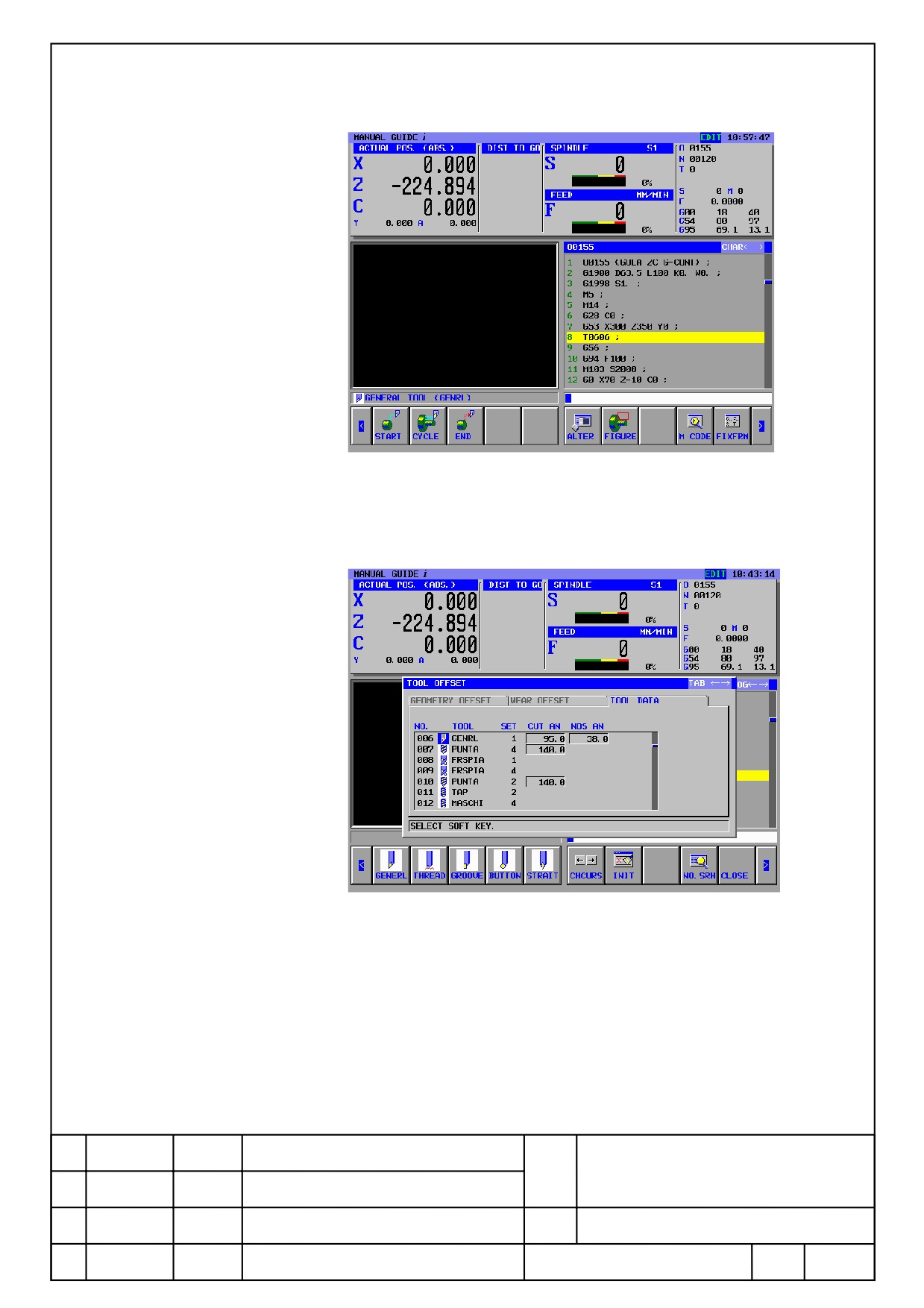
(3) Press [ALTER] or INPUT key. However, in MDI mode, machining
simulation, and NC conversion, [ALTER] is not displayed, so press
INPUT key.
(4) Tool database screen (tool information tab at tool offset screen) is
displayed. At this event, a cursor move to the data of tool offset
number corresponding to tool geometry offset number (lathe), or tool
radius compensation number (machining center)
(5) Confirm or input a tool information.
(6) By pressing [CLOSE] to close a tool database screen. At this event, a
cursor return to a tool offset command.
FANUC MANUAL GUIDE i
Name
(Series16i/18i/21i-MB/TB)
OPERATOR’S MANUAL
Draw.
B-63874EN/05-1
Ed.
Date
Design
Description
Page
33/100
FANUC LTD.
12
Display Tool Icon Function
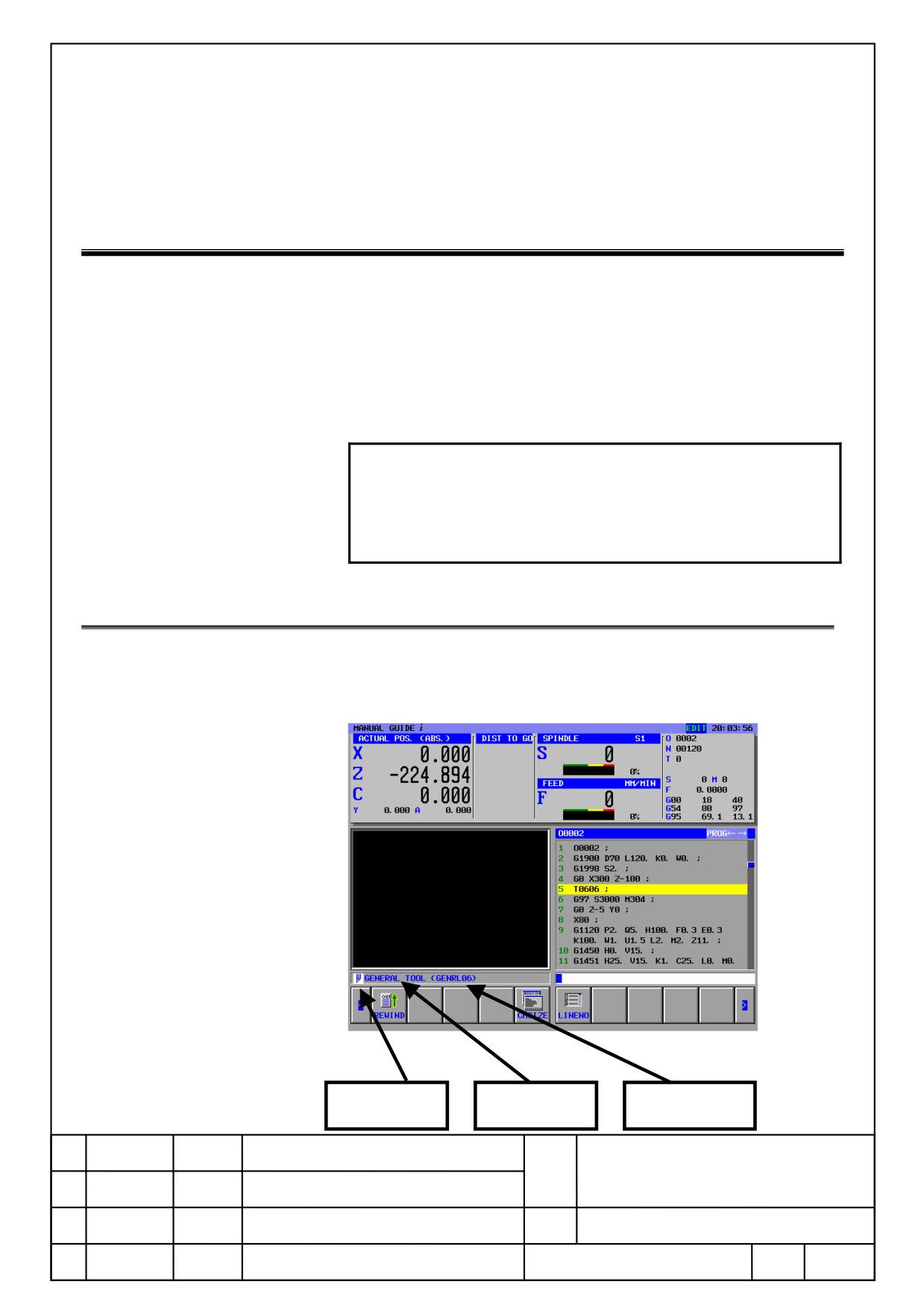
When tool database function is available, if the cursor is on the offset
command, tool icon and tool name corresponding to the number is displayed
on the guidance message screen.
The offset command is T code on lathes without tool management function.
And it is D code on lathes with tool management function or machining
centers.
NOTE
1 This function is unavailable on compound machines.
2 This function is unavailable when there is the offset memory
switching function.
3 Set a parameter No.14705#7=1 to use this function.
12.1. DETAILS
When place a cursor to tool offset command defined a data of tool database
tool icon, tool type, and tool name are displayed.
TOOL ICON
TOOL KIND
TOOL NAME
FANUC MANUAL GUIDE i
Name
(Series16i/18i/21i-MB/TB)
OPERATOR’S MANUAL
Draw.
B-63874EN/05-1
Ed.
Date
Design
Description
Page
34/100
FANUC LTD.

NOTE
1 On the lathe, tool data that is registered a same number to tool
geometry offset command are displayed. It is not a offset number of
tool wear.
2 On machining center, tool data registered to the same number of
tool diameter compensation command is displayed.
FANUC MANUAL GUIDE i
Name
(Series16i/18i/21i-MB/TB)
OPERATOR’S MANUAL
Draw.
B-63874EN/05-1
Ed.
Date
Design
Description
Page
35/100
FANUC LTD.

13
Machining Time Display Function
for Series 30i
13.1. Details
For Series 30i, Machining time display function is available.
The difference from Series 16i are as followings.
1. Inserting a machining time is possible in EDIT mode.
2. In MEM mode, a machining time cannot be inserted to a file selecting
at foreground.
In details of this function, refer to [Chapter 23 “Machining Time Display
Function”] of [II. Operations] on [B-63874JA/05 FANUC MANUAL GUIDE i
operator’s manual].
FANUC MANUAL GUIDE i
Name
(Series16i/18i/21i-MB/TB)
OPERATOR’S MANUAL
Draw.
B-63874EN/05-1
Ed.
Date
Design
Description
Page
36/100
FANUC LTD.
14
Improvement of Input Item for Milling
14.1. Outline
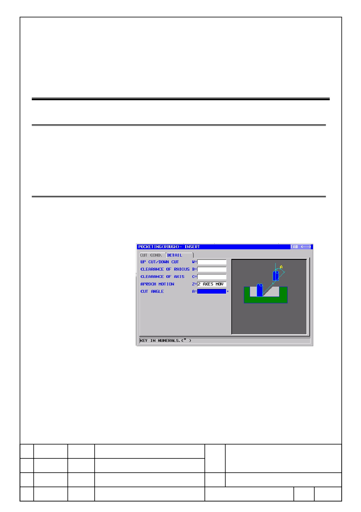
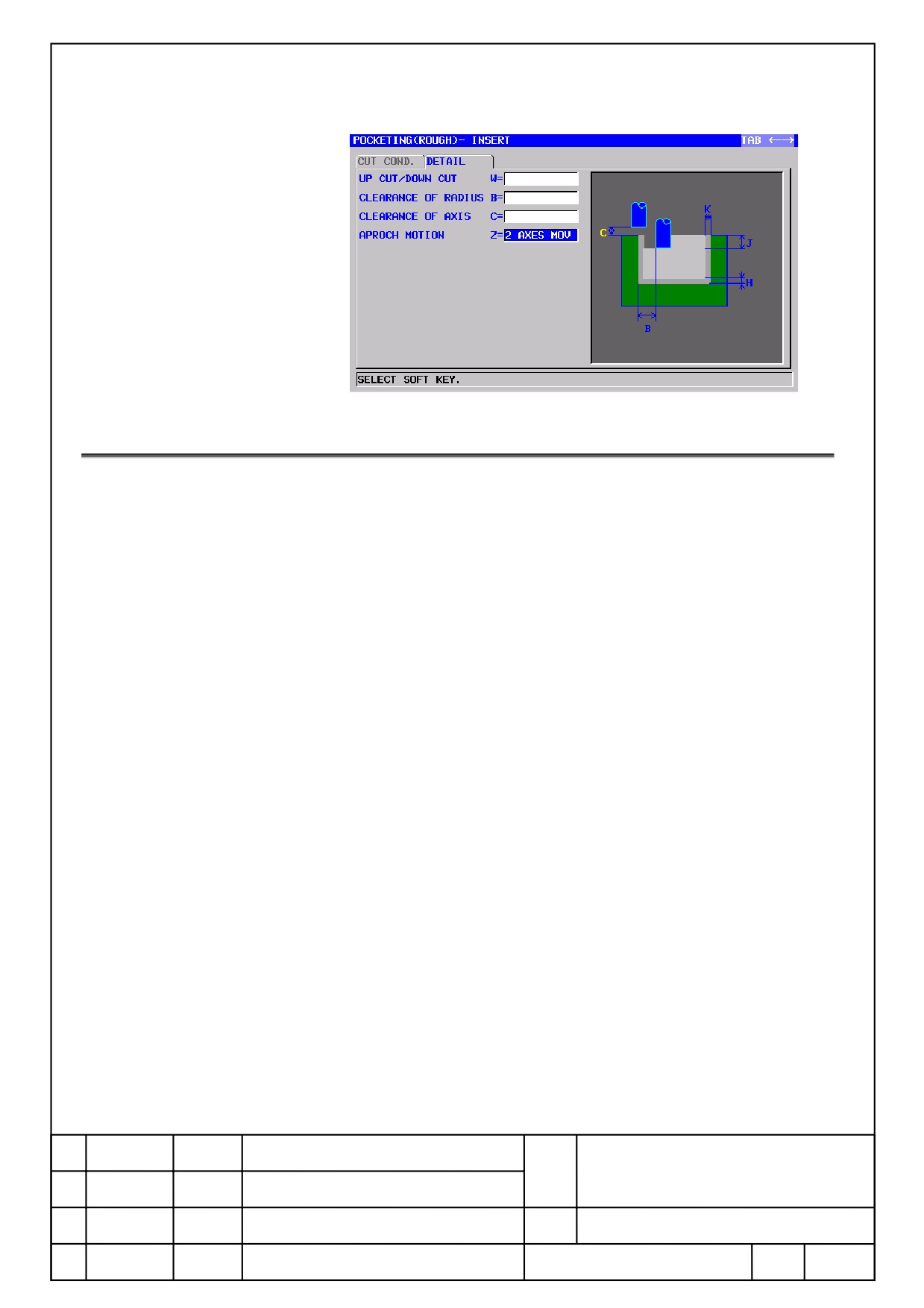
[Approach Motion] is undisplayed when a option of control axis number
expansion is unavailable. [Cut Angle] can be set by a parameter.
Undisplay [Approach Motion] when there is no option for simultaneous
control axis number expansion.
14.2. Details
The below screen is [Detail] tab at pocketing (Rough).
A following is displaying the input items [Approach Motion] and [Cut
Angle].
The screen below is the condition to undisplay the input item [Cut Angle] by
setting the parameter 27061<#5> to 1.
FANUC MANUAL GUIDE i
Name
(Series16i/18i/21i-MB/TB)
OPERATOR’S MANUAL
Draw.
B-63874EN/05-1
Ed.
Date
Design
Description
Page
37/100
FANUC LTD.
14.3.
Related Cycles
Improved cycle menus are listed below.
● Machining block related to approach motion.
Hole Machining
Center drilling
: G1000
Drilling
: G1001
Tapping
: G1002
Reaming
: G1003
Boring
: G1004
Fine Boring
: G1005
Back Boring
: G1006
Facing
Rough
: G1020
Finishing
: G1021
Contouring
Outer Wall Rough
: G1060
Outer Wall Bottom Finish
: G1061
Outer Wall Side Finish
: G1062
Outer Wall Chamfer
: G1063
Inner Wall Rough
: G1064
Inner Wall Bottom Finish
: G1065
Inner Wall Side Finish
: G1066
Inner Wall Chamfer
: G1067
Partial Wall Rough
: G1068
Partial Wall Bottom Finish
: G1069
FANUC MANUAL GUIDE i
Name
(Series16i/18i/21i-MB/TB)
OPERATOR’S MANUAL
Draw.
B-63874EN/05-1
Ed.
Date
Design
Description
Page
38/100
FANUC LTD.

Partial Wall Side Finish
: G1070
Partial Wall Chamfer
: G1071
Embossing
Rough
: G1080
Bottom Finish
: G1081
Side Finish
: G1082
Chamfer
: G1083
Pocketing
Rough
: G1040
Bottom Finish
: G1041
Side Finish
: G1042
Chamfer
: G1043
Grooving
Rough
: G1050
Bottom Finish
: G1051
Side Finish
: G1052
Chamfer
: G1053
A-Axis Grooving
Rough
: G1058
B-Axis Grooving
Rough
: G1054
C-Axis Grooving
Rough
: G1056
● Machining block related to cut angle
Pocketing
Rough
: G1040
Bottom Finish
: G1041
FANUC MANUAL GUIDE i
Name
(Series16i/18i/21i-MB/TB)
OPERATOR’S MANUAL
Draw.
B-63874EN/05-1
Ed.
Date
Design
Description
Page
39/100
FANUC LTD.
15
Imprvement of Displaying Position of
Input Items [SIDE FINISH AMOUNT]
and [BOTTOM FINISH AMT.]
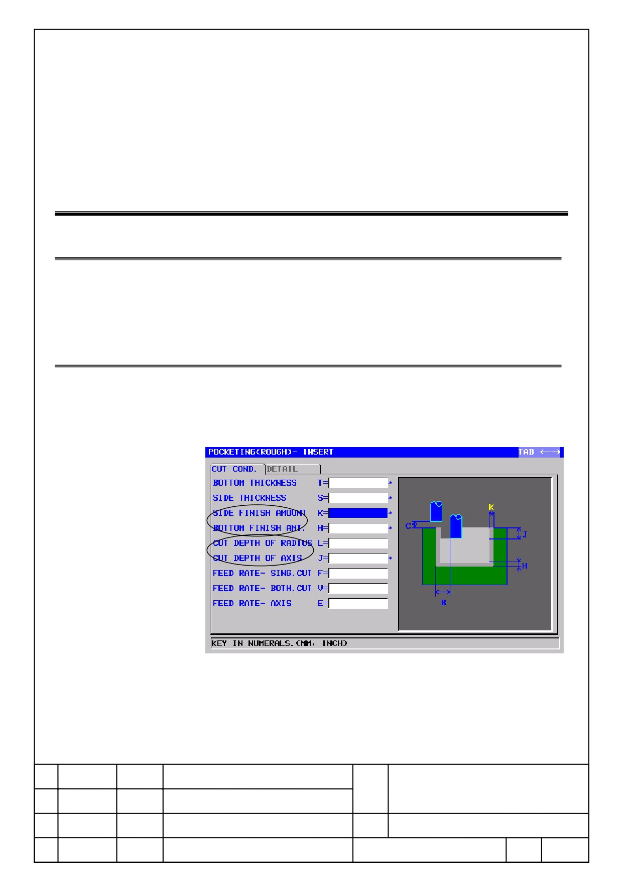
15.1. Outline
Switch the order of input items [Cut Depth of Radius], [Cut Depth of Axis],
[Side Finish Amount], and [Bottom Finish Amount] by setting the
parameter 27002<#5> to 1.
15.2. Details
The following screen is a new spec pocketing (Rough) screen. The input
items [Side Finish Amount], [Bottom Finish Amount] were placed upper
part than the input items [Cut Depth of Radius], [Cut Depth of Axis].
FANUC MANUAL GUIDE i
Name
(Series16i/18i/21i-MB/TB)
OPERATOR’S MANUAL
Draw.
B-63874EN/05-1
Ed.
Date
Design
Description
Page
40/100
FANUC LTD.

15.3. Related Cycles
Improved cycle menus are listed below.
・Each Roughing of Contouring
(G1060,G1064,G1068)
・Pocketing Rough
(G1040)
・Grooving Rough
(G1050)
・Embossing Rough
(G1080)
FANUC MANUAL GUIDE i
Name
(Series16i/18i/21i-MB/TB)
OPERATOR’S MANUAL
Draw.
B-63874EN/05-1
Ed.
Date
Design
Description
Page
41/100
FANUC LTD.
16
Improvement of the Input Item for Drilling
16.1. Outline
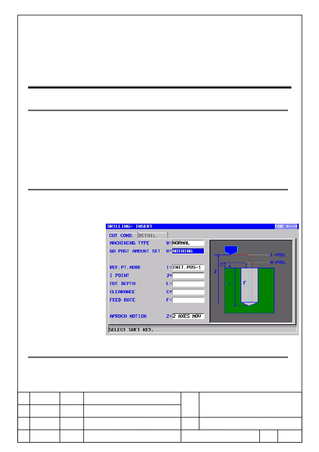
Whether to set or to unset the input item [GO PAST AMOUNT] at drilling
can be set by the input item [GO PAST AMOUNT SET]. When the
parameter 27020<#0> is set to 0, the input item [GO PAST AMOUNT SET]
is not displayed.
[TOOL DIAMETER] and [NOSE ANGLE] are also added, so that the [GO
PAST AMOUNT] can calculated by pressing [CALCULATE] soft key.
16.2.
[Cut Condition] Tab
A below figure is a [CUT COND.] tab. Input item [GO PAST AMOUNT
SET] is added, and [NOTHING] and [SETTING] can be selectable.
16.3.
[Detail] Tab
The below figure is a [DETAIL] tab. When selecting [SETTING] in input
item [GO PAST AMOUNT SET] at [Cut Condition] tab, input items [TOOL
DIAMETER], [NOSE ANGLE], and [GO PAST AMOUNT] at [DETAIL] tab.
FANUC MANUAL GUIDE i
Name
(Series16i/18i/21i-MB/TB)
OPERATOR’S MANUAL
Draw.
B-63874EN/05-1
Ed.
Date
Design
Description
Page
42/100
FANUC LTD.
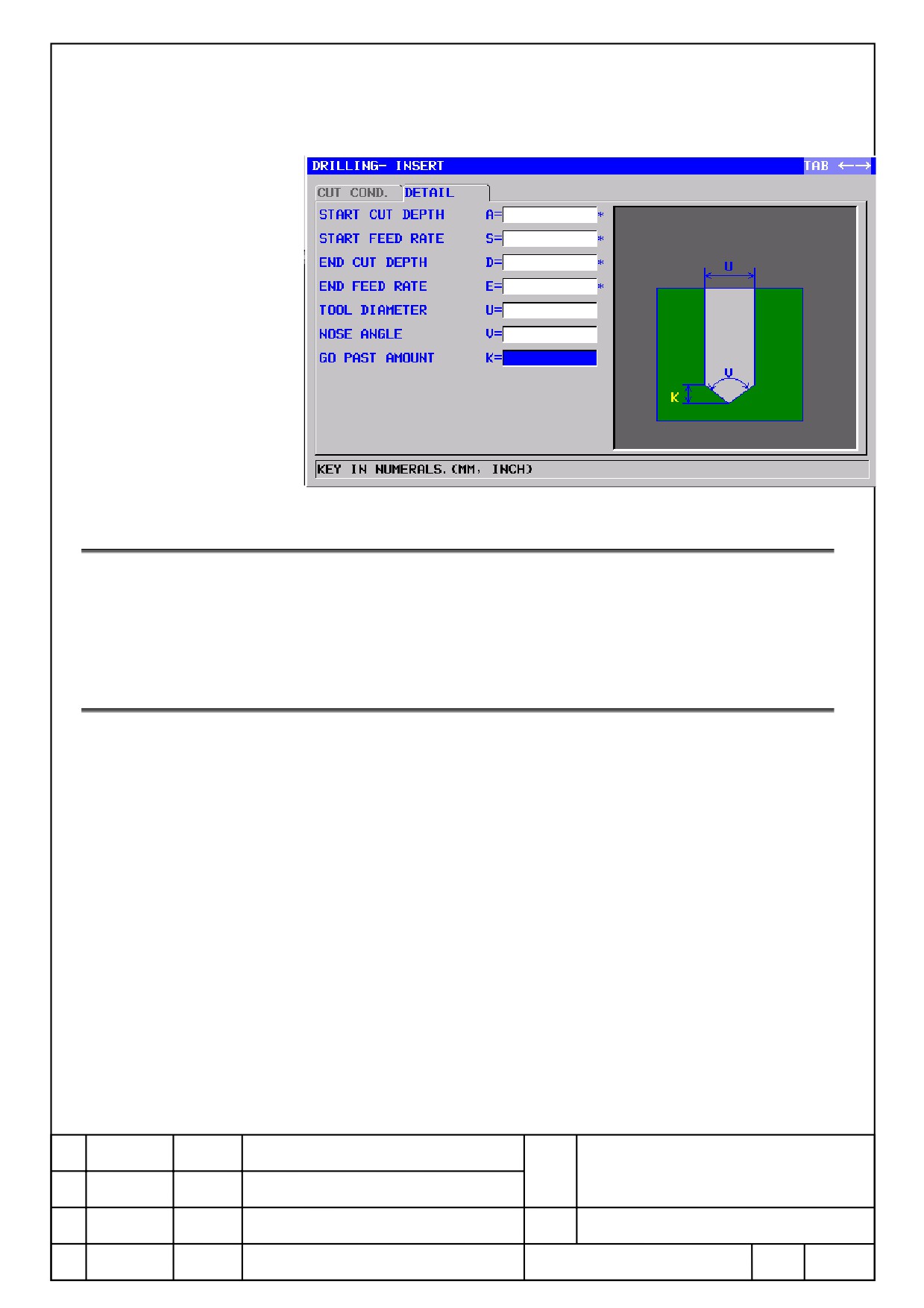
16.4. Calculation Function
When enter the data to input items [TOOL DIAMETER] and [NOSE
ANGLE] at [DETAIL] tab, and press [CALCULATE] soft key, input item
[GO PAST AMOUNT] is set the value automatically calculated.
16.5. Related Cycles
Improved Machining Types are listed below.
・ Drilling :G1001
(Tool Rotation M Type)
・ Drilling :G1111
(Tool Rotation T Type)
・ Drilling :G1101
(Work Rotation)
FANUC MANUAL GUIDE i
Name
(Series16i/18i/21i-MB/TB)
OPERATOR’S MANUAL
Draw.
B-63874EN/05-1
Ed.
Date
Design
Description
Page
43/100
FANUC LTD.
17
Improvement of Input Item for Tapping
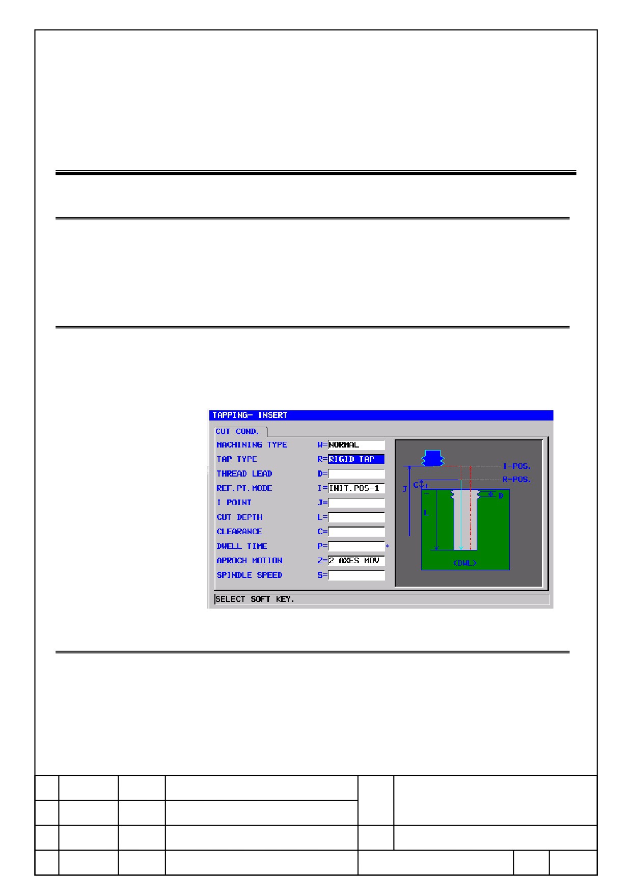
17.1. Outline
At tapping cycle input screen, input items [TAP TYPE] and [SPINDLE
SPEED] are moved to [CUT CONDITION] tab.
A default of input item [TAP TYPE] is also changed by parameter.
17.2. New Tapping Cycle G1002 Screen
For a result [RIGIT TAP] tab are deleted, and these input items are moved
to a front tab, an operator can consider about tap type. Input item [TAP
TYPE] are consistently displayed.
17.3. Default of [Tap Type]
The following soft key and default displayed when place a cursor to [TAP
TYPE].
1.When there is no option of [RIGIT TAP]
FANUC MANUAL GUIDE i
Name
(Series16i/18i/21i-MB/TB)
OPERATOR’S MANUAL
Draw.
B-63874EN/05-1
Ed.
Date
Design
Description
Page
44/100
FANUC LTD.
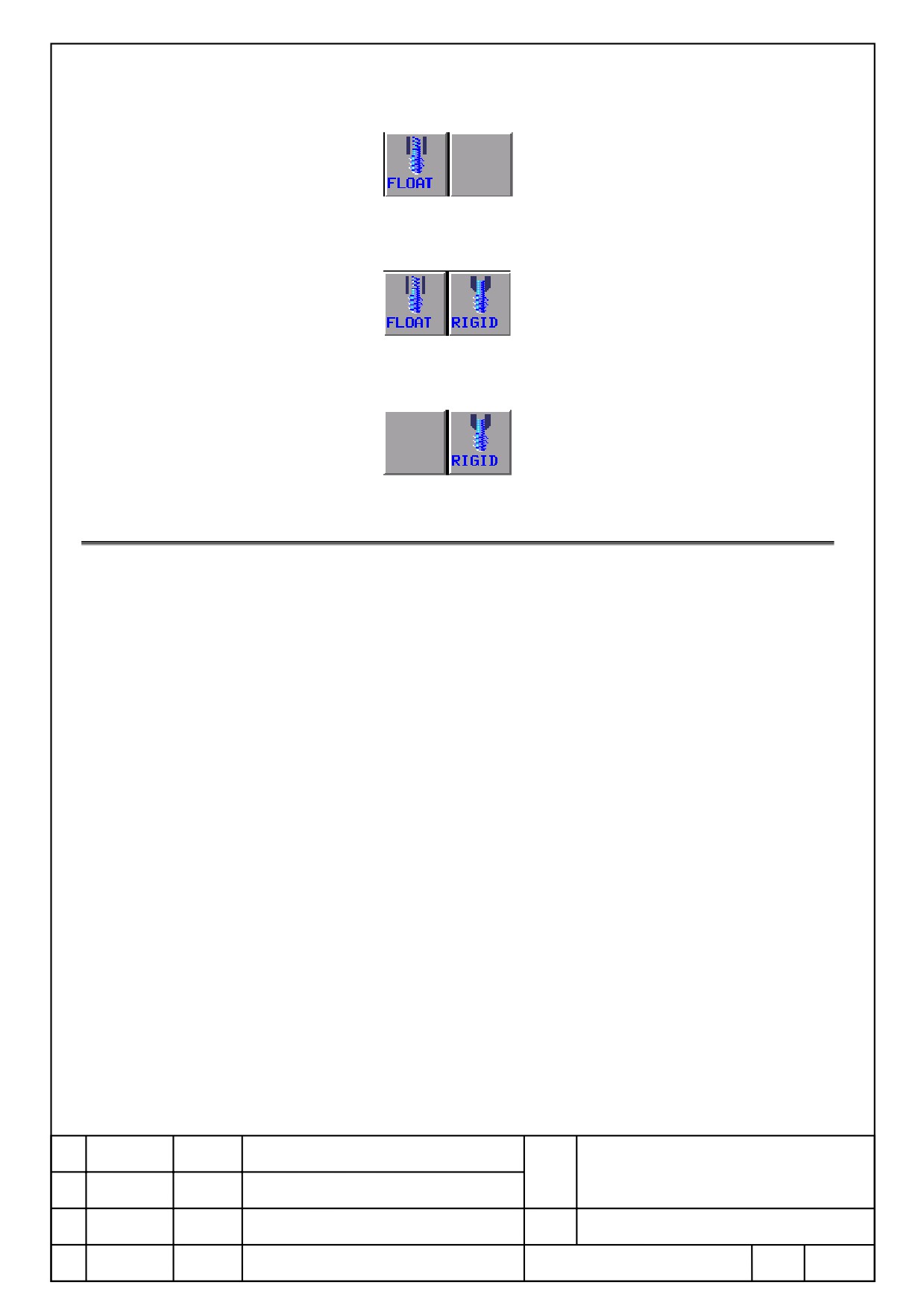
Default Value:[FLOAT TAP]
2.When there is an option of [RIGIT TAP] and parameter No.5200 #0=0
Default Value:[RIGIT TAP]
3.When there is an option of [RIGIT TAP] and parameter No.5200 #0=1
Default Value:[RIGIT TAP]
17.4. Related Cycles
Improved cycle machining types are as followings.
・Tapping
: G1002(Tool Rotation M Type)
・Tapping
: G1112(Tool Rotation T Type)
・Tapping
: G1102(Work Rotation)
FANUC MANUAL GUIDE i
Name
(Series16i/18i/21i-MB/TB)
OPERATOR’S MANUAL
Draw.
B-63874EN/05-1
Ed.
Date
Design
Description
Page
45/100
FANUC LTD.
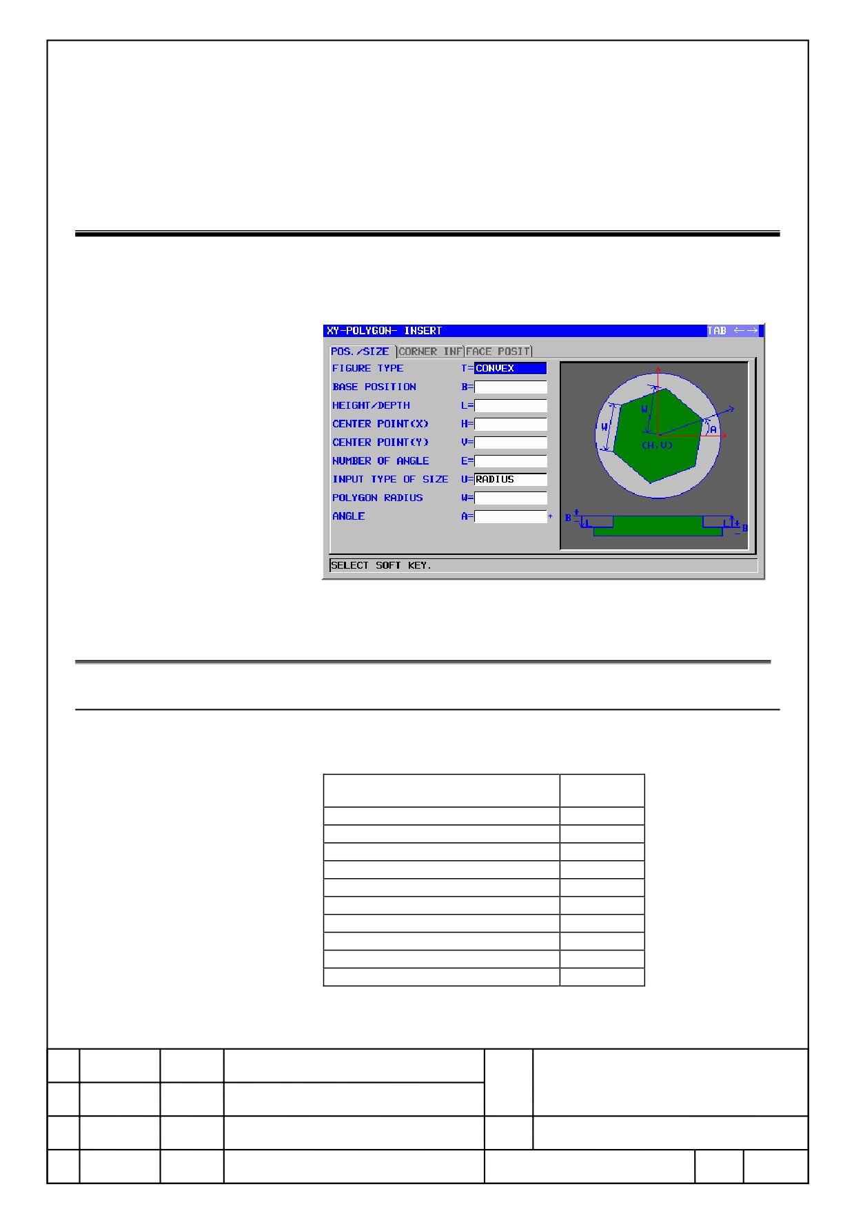
18
Polygon Fixed Figure
”Polygon” can be used at fixed figure on XY, YZ, and XC plane for milling.
This function is available by set the parameter No.27095#2 = 1.
Example: XY plane polygon convex figure of Contouring
18.1. Details of Fixed Figure (Polygon) Cycle(G1x25)
18.1.1
Available Combination of Machining
Matching machining type block is as followings
Machining Type
Availability
Hole Machining (M Type)
×
Facing
○
Contouring (exclude parts machining)
○
Pocketing
○
Grooving
○
Hole Machining (T Type:Tool Rotation)
×
Hole Machining (work Rotation)
×
Turning
×
Turning Groove
×
Threading
×
FANUC MANUAL GUIDE i
Name
(Series16i/18i/21i-MB/TB)
OPERATOR’S MANUAL
Draw.
B-63874EN/05-1
Ed.
Date
Design
Description
Page
46/100
FANUC LTD.
18.1.2
G-Code
G code of polygon fixed figure at each machining plane are as follows.
Plane
G code
XY
G1225
YZ
G1325
XC
G1525
18.1.3
Format
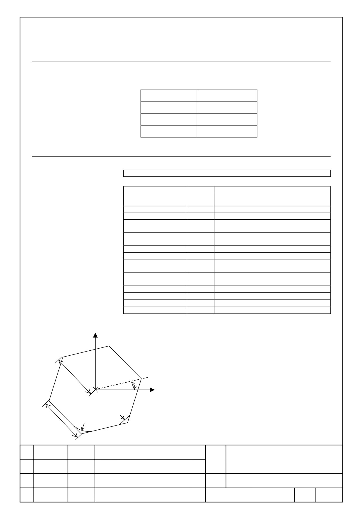
G1x25 Tt Bb Ll Hh Vv Ee Uu Ww Aa Dd Cc Rr Zz Yy;
Meanings
Address
Explanation
FIGURE TYPE
T
T1: FACE, T2: CONVEX, T3: CONCAVE,
T4: GROOVE
BASE POSITION
B
HEIGHT/DEPTH
L
Undisplay at Facing
CENTER POINT
H
(THE FIRST AXIS)
CENTER POINT
V
(THE SECOND AXIS)
NUMBER OF ANGLE
E
Positive integer value from 3 to 99.
INPUT TYPE OF SIZE
U
U1: POLYGON RADIUS, U2: SIDE LENGTH
POLYGON RADIUS/
W
SIDE LENGTH
ANGLE
A
Inclination from the first axis.
GROOVE WIDTH
D
Specify only used at Grooving.
CORNER TYPE
C
C1: NOTHING, C2: CHAMFER, C3: CORNER R
CORNER SIZE
R
FACE POSITION
Z
Z1:+FACE, Z2:-FACE,
ROTATION AXIS NAME
Y
※ “Corner Position” is displayed with added tab by set parameter
No.27000#4
= 1.
※ “Rotation Axis Name” is displayed on XC plane, by set parameter
No.27001#0 = 1.
W
A
(H, V)
R
R
W
FANUC MANUAL GUIDE i
Name
(Series16i/18i/21i-MB/TB)
OPERATOR’S MANUAL
Draw.
B-63874EN/05-1
Ed.
Date
Design
Description
Page
47/100
FANUC LTD.
19
Reuse of Blank Form Data at Machining
Figure Entry
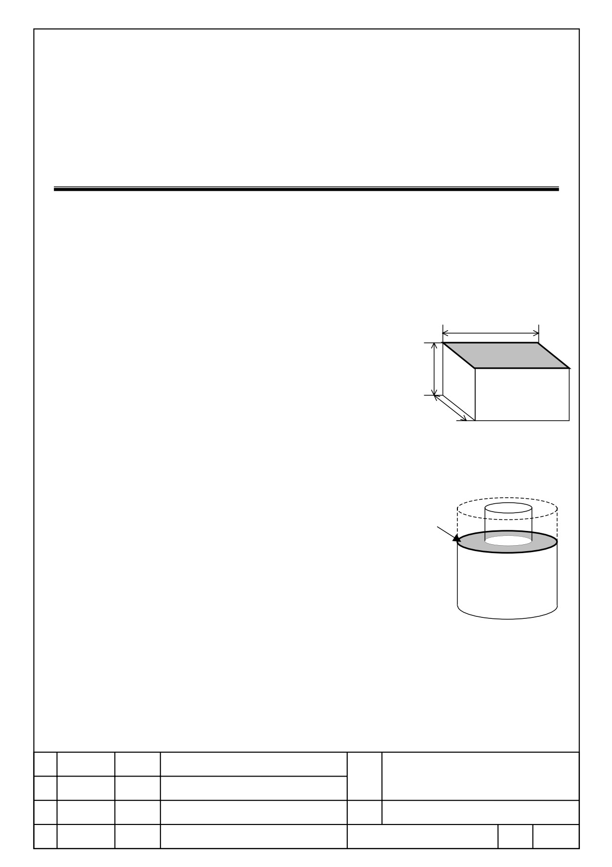
Blank form data can reuse at machining figure entry. Measurement data
(radius or length of each lines) entered at element figure is automatically
copied to input items of fixed form figure or free figure. This function is
available by setting a parameter No.27095#1=1.
1.At facing, blank form data of cutting face can be reused as cutting area.
D
Cutting Area of Facing
H
B
2.At Embossing, blank form data can be reused as outside borderline of
embossing.
Outside Borderline of Embossing of Cut Area
At other machining cycle, it is easy to enter the input item automatically
copied by using calculating function.
FANUC MANUAL GUIDE i
Name
(Series16i/18i/21i-MB/TB)
OPERATOR’S MANUAL
Draw.
B-63874EN/05-1
Ed.
Date
Design
Description
Page
48/100
FANUC LTD.
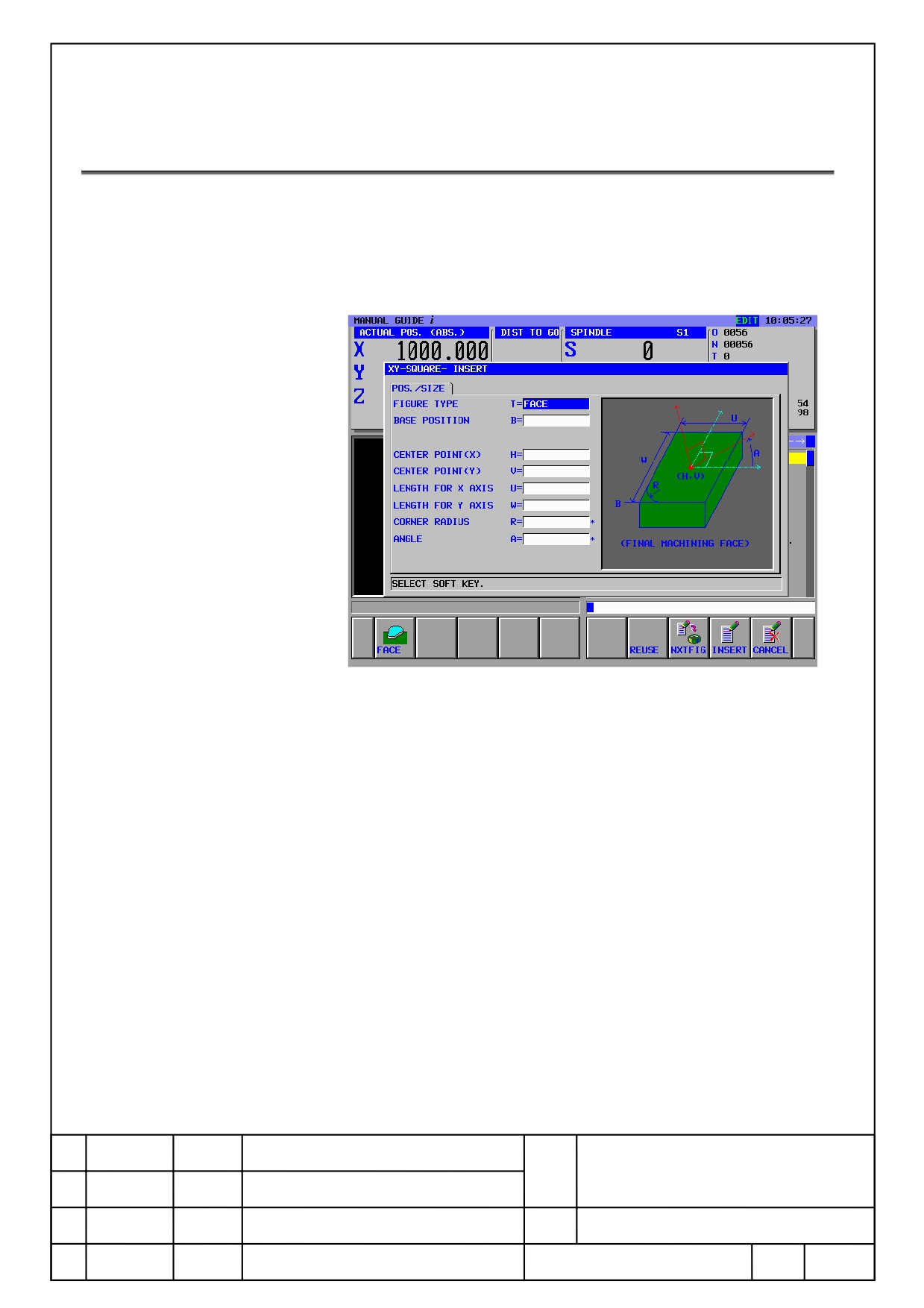
19.1. Operation
(1) Enter Fixed Figure
When reuse of blank form data for machining figure data is available
(parameter No.27095#1 = 1), it automatically copied to each items at
figure input screen by pressing [REUSE] soft key.
Note: When the plane of blank is circle figure, even if the figure data is
tried to copy to rectangle, an alarm message “FIGURE DATA IS
WRONG” is displayed.
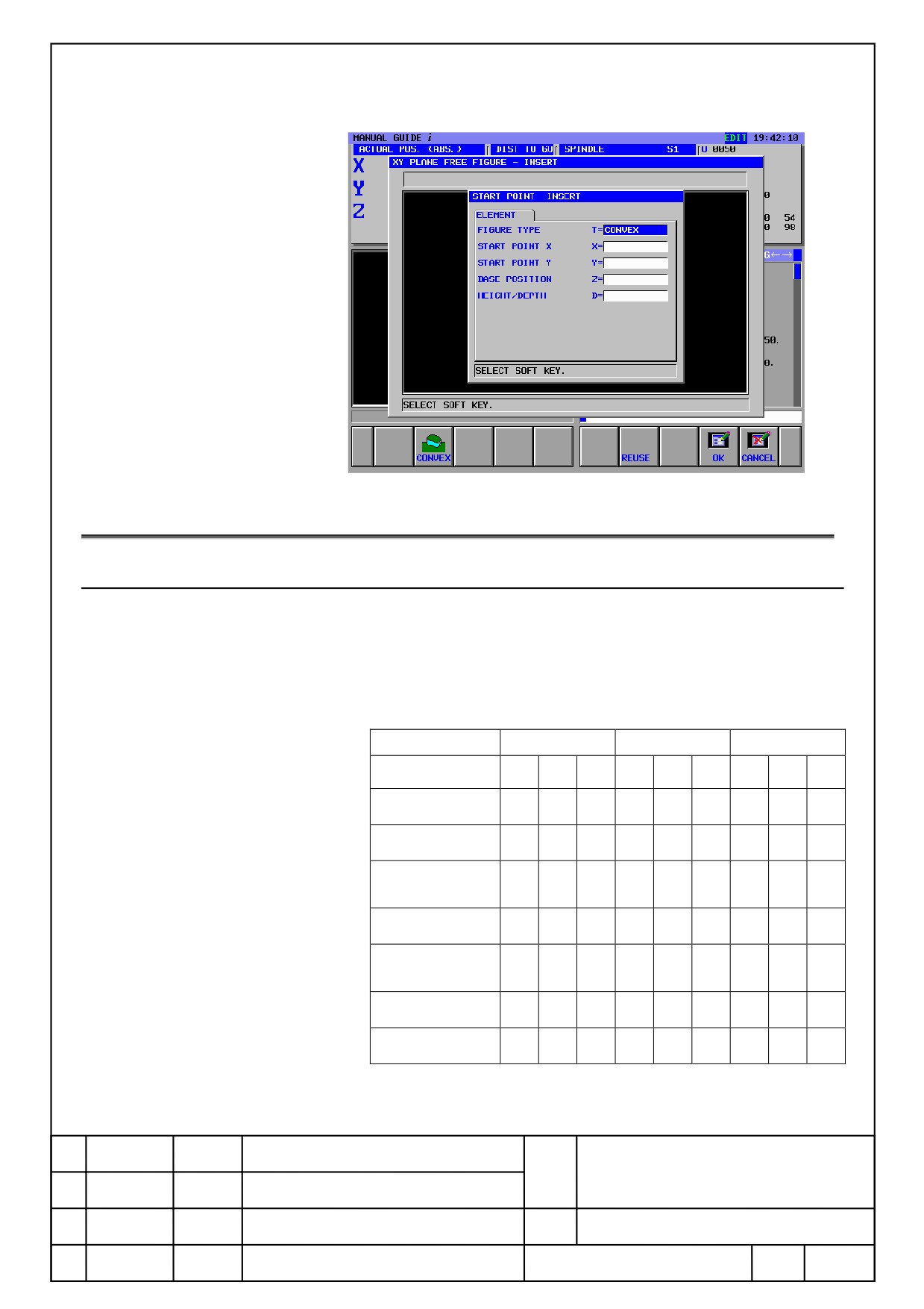
(1) Enter Free Figure
When reuse of blank form data for machining figure data is available
(parameter No.27095#1 = 1), it automatically copied to each items at
figure input screen by pressing [REUSE] soft key.
After the entry of requirement items of start point (Standard position,
Height/ Depth), press [REUSE] soft key. Free figure is not drew by
pressing [INSERT] soft key followed by pressing [REUSE] soft key
without entered a standard position, or height/depth.
FANUC MANUAL GUIDE i
Name
(Series16i/18i/21i-MB/TB)
OPERATOR’S MANUAL
Draw.
B-63874EN/05-1
Ed.
Date
Design
Description
Page
49/100
FANUC LTD.
19.2.
Reuse Condition
19.2.1
Blank and Available Machining Figure/Plane
At each blank form, the relation of reusable machining figure and plane are
listed below.
(1) Fixed Figure
Rectangular
Arc
Polygon
XY
YZ
XC
XY
YZ
XC
XY
YZ
XC
Rectangular
○
○
○
Cylinder
○
○
Cylinder
○
(X axis rotation)
Hollow Cylinder
○
○
Hollow Cylinder
○
(X axis rotation)
Prism
○
○
Hollow Prism
○
○
FANUC MANUAL GUIDE i
Name
(Series16i/18i/21i-MB/TB)
OPERATOR’S MANUAL
Draw.
B-63874EN/05-1
Ed.
Date
Design
Description
Page
50/100
FANUC LTD.
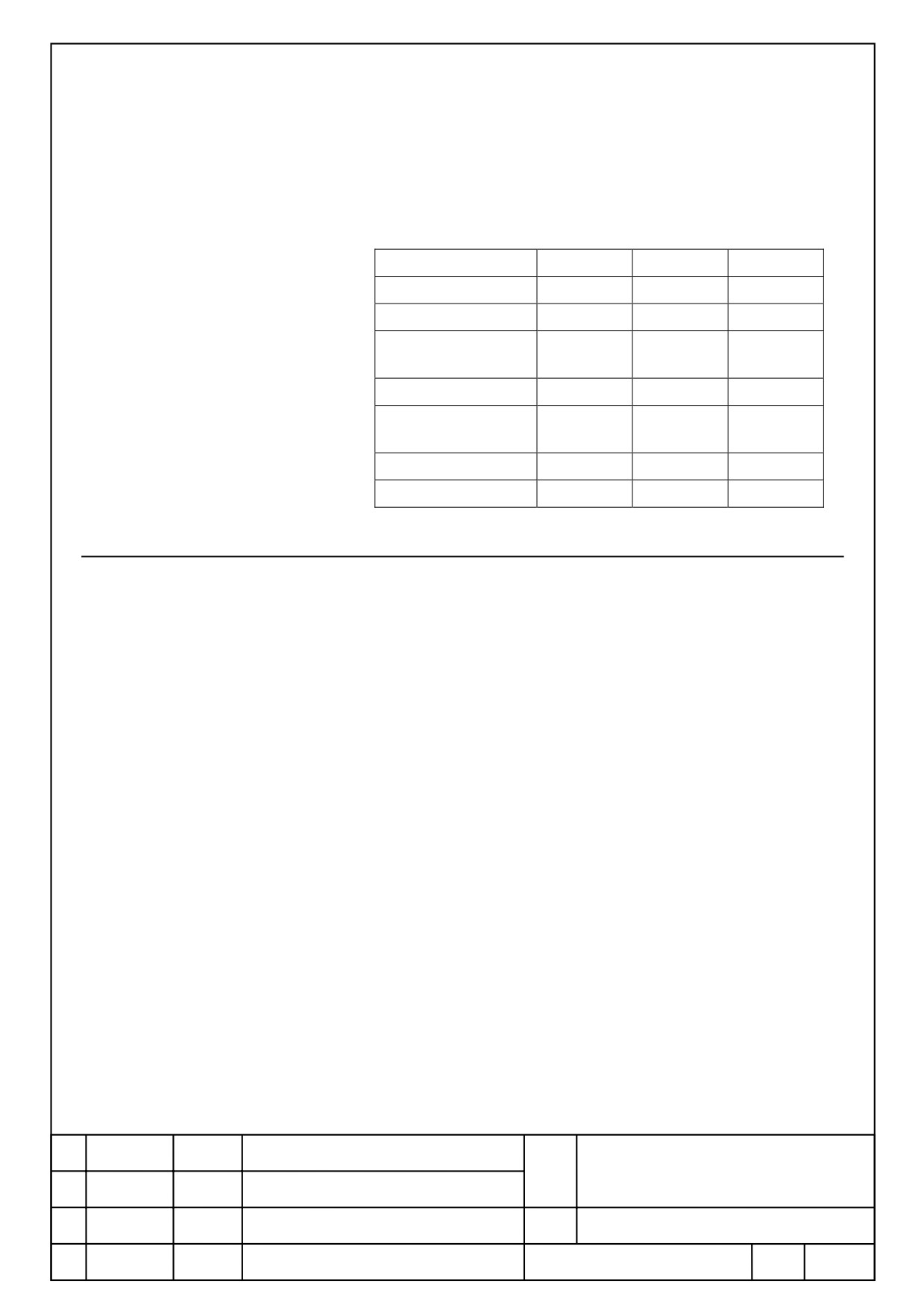
Reuse is available only at machining figure corresponding to blank
form data.
(2) Free Figure
XY
YZ
XC
Rectangular
○
○
○
Cylinder
○
○
Cylinder
○
(X axis rotation)
Hollow Cylinder
○
○
Hollow Cylinder
○
(X axis rotation)
Prism
○
○
Hollow Prism
○
○
19.2.2
Blank Figure Data to be Used
(1) Timing to update a blank form data to reuse.
1) When alter or create a blank and register, the blank form data is saved
and used as reuse data at machining figure entry screen.
2) When machining program is opened at O list, program from a top of to
a maximum block set by a parameter No. 27018(SRCHBLNK) are
analyzed, and save an blank form data placed from the beginning, and
used as reuse data at machining figure entry screen.
(2) Timing to clear the blank form data to reuse.
1) Saved blank form data is cleared when powered off.
2) A part of the first blank form data in a block set by a parameter
NO.27018 (SRCHBLNK) is deleted (Example: Only an element width
B of rectangular is deleted), saved blank form data to reuse is cleared.
Note 1: Reuse function is assuming only one blank form block existing at
one machining. When there are multiple blank form blocks in a
machining program, the corresponding blank form block is register
again to edit a machining figure block for 2nd blank for normal
operation.
Note 2: When there is a sub program in a block range set by parameter
No.27018 (SRCHBLNK), it does not analyze in the sub program.
FANUC MANUAL GUIDE i
Name
(Series16i/18i/21i-MB/TB)
OPERATOR’S MANUAL
Draw.
B-63874EN/05-1
Ed.
Date
Design
Description
Page
51/100
FANUC LTD.
20
Changing Input Screen of Thickness Item
Input items [Bottom Thickness] and [Side Thickness] can be entered at
figure entry screen instead of cycle entry screen. With using this function,
there are some advantages as following.
1:
[Bottom Thickness] and [Side Thickness] at cycle entry screen and
[Base Position] and [Height/Depth] at figure entry screen are closely
related. These items can enter at the same block.
2: Multiple figure blocks can enter to one processing. By entering [Bottom
Thickness] and [Side Thickness] at figure block, [Thickness] can be set
to multiple machining figure individually.
This function is available by set a parameter No.27095#0=1.
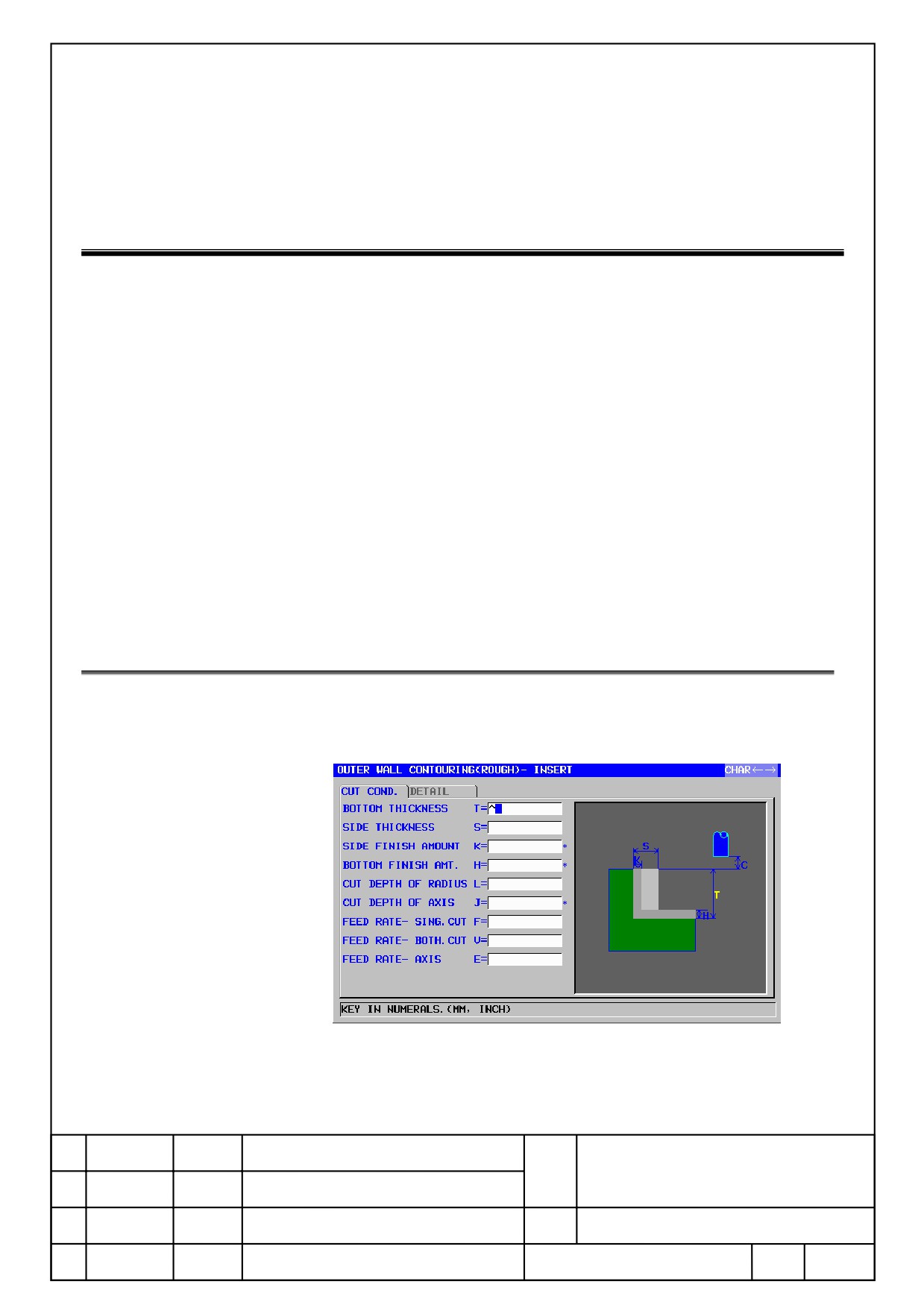
20.1. Cycle Entry Screen
Cycle entry screen is displayed as figure below by setting a parameter
No.27095#0
(1)
NO.27095#0=0
Example:Outer Wall Contouring (Rough)
FANUC MANUAL GUIDE i
Name
(Series16i/18i/21i-MB/TB)
OPERATOR’S MANUAL
Draw.
B-63874EN/05-1
Ed.
Date
Design
Description
Page
52/100
FANUC LTD.
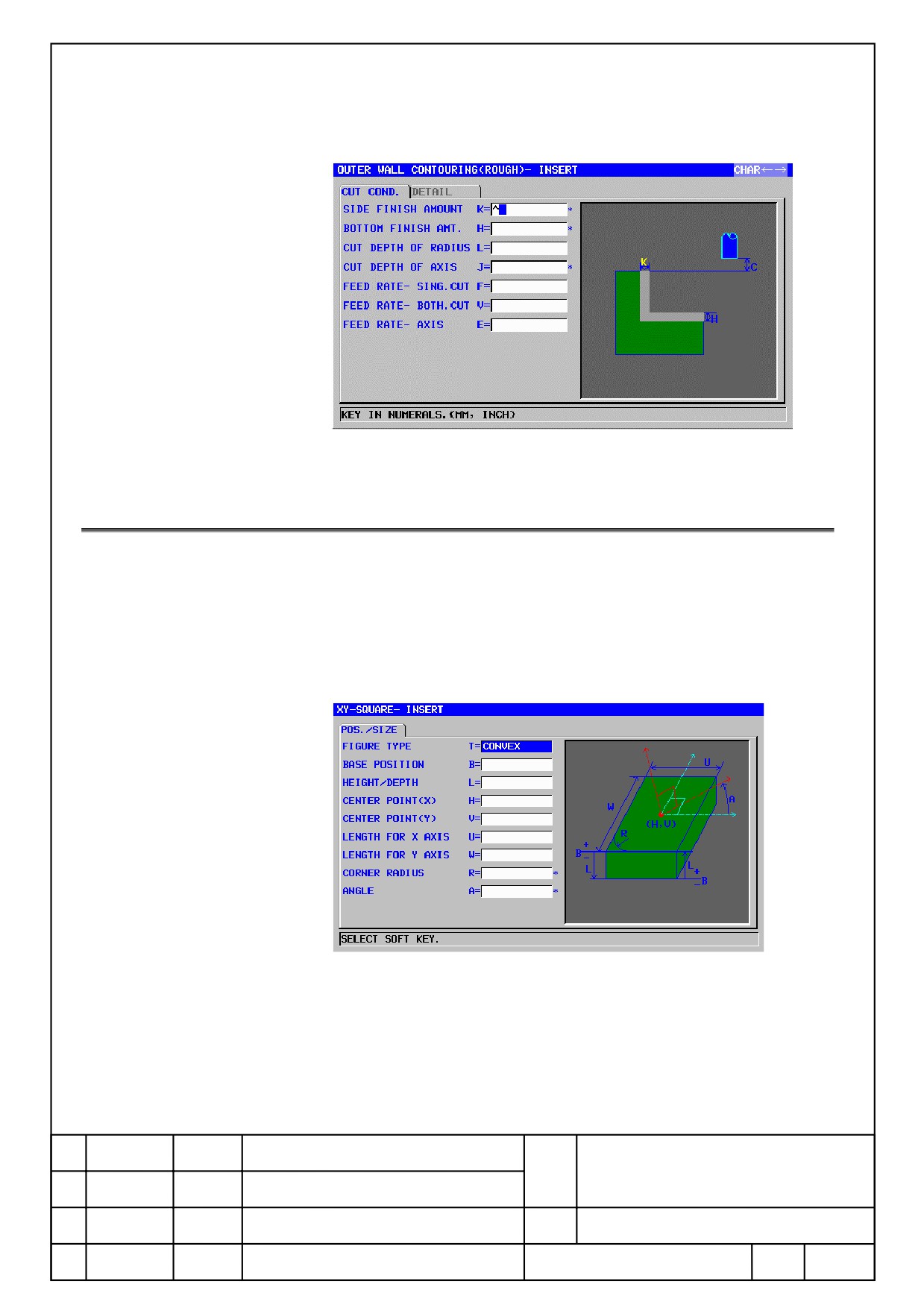
(2)
NO.27095#0=1
Example:Outer Wall Contouring(Rough)
20.2. Figure Entry Screen
Figure entry screen is displayed as a figure below by setting a parameter
No.27095#0. When a parameter No.27095#0=1,
<Thickness> tab is
displayed, and [Base Thickness] and [Side Thickness] can be input.
(1)
NO.27095#0=0
Example:XY plane Square
(2)
NO.27095#0=1
FANUC MANUAL GUIDE i
Name
(Series16i/18i/21i-MB/TB)
OPERATOR’S MANUAL
Draw.
B-63874EN/05-1
Ed.
Date
Design
Description
Page
53/100
FANUC LTD.
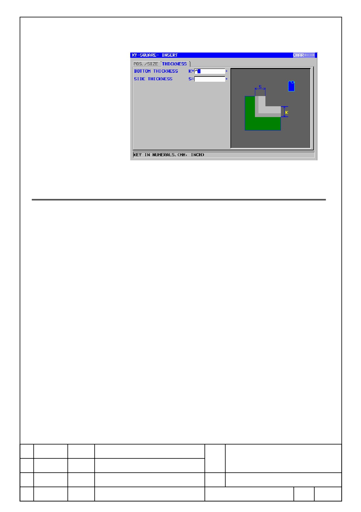
Example:XY plane Square
20.3. Mutuality
When enable a setting of input items
[Bottom Thickness] and
[Side
Thickness] at figure entry screen, machining program created at a setting of
[bottom thickness] and [Side Thickness] at cycle entry screen cannot be
used as it stands. It needs to alter partially.
Depending on a setting, alarms listed below would occur.
1. When input bottom / side thickness at figure entry screen (Parameter
No.27095#0=1).
・ At machining type block, a bottom thickness or side thickness exists.
→ Alarm Number 3043(16i), 3543(30i) “WRONG THICKNESS”
・ At machining figure block, even bottom thickness or side thickness is
required item, a return value does not exist.
→ Alarm Number 3016(16i), 3516(30i) “NO NECESSARY ADDRESS”
2. When input bottom / side thickness at cycle entry screen. (Parameter
No.27095#0=0)
・ At machining figure block, a bottom thickness or side thickness exists
→ Alarm Number 3043(16i), 3543(30i) “WRONG THICKNESS”
Note: When bottom / side thickness is omissible at machining type block,
it won’t alarm out with leaving a blank to the item of bottom/side
thickness.
When bottom/side thickness is required item
(a part of plane
contouring), it alarm out as “NO NECESSARY ADDRESS”.
FANUC MANUAL GUIDE i
Name
(Series16i/18i/21i-MB/TB)
OPERATOR’S MANUAL
Draw.
B-63874EN/05-1
Ed.
Date
Design
Description
Page
54/100
FANUC LTD.
21
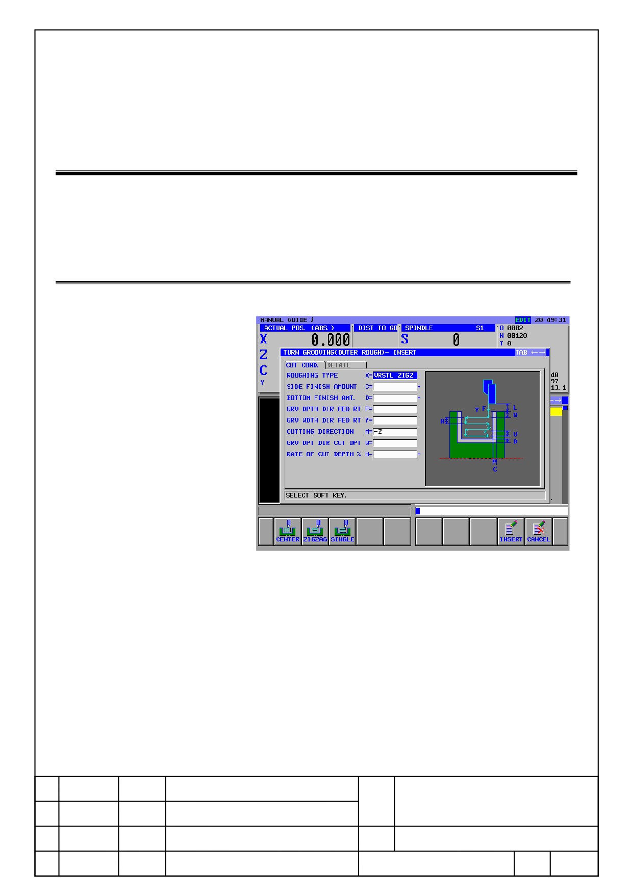
Turning Grooving by Versatile Tool
At turning grooving, input item [Roughing Type] is added.. When select
versatile ZIGZAG, or versatile one direction by roughing type, turning
grooving by versatile tool can be operated.
21.1. Data Entry Screen of Turning Grooving
Input item [Roughing Type] is added to the following machining type block
screen.
[Versatile ZIGZAG] and [Versatile 1 Direction] is added to [Roughing Type].
By selecting these, turning grooving by versatile tool is available.
(1)
Outer Rough of Turning Grooving(G1130)
(2)
Inner Rough of Turning Grooving(G1131)
(3)
Facing Rough of Turning Grooving(G1132)
(4)
Outer Rough and Finishing of Turning Grooving(G1133)
(5)
Inner Rough and Finishing of Turning Grooving(G1134)
(6)
Facing Rough and Finishing of Turning Grooving(G1135)
FANUC MANUAL GUIDE i
Name
(Series16i/18i/21i-MB/TB)
OPERATOR’S MANUAL
Draw.
B-63874EN/05-1
Ed.
Date
Design
Description
Page
55/100
FANUC LTD.