FANUC MANUAL GUIDE i. OPERATOR’S MANUAL - page 29

B.ALARMS
APPENDIX
B-63874EN/05
Alarm
Description
16i
30i
Cause
The tool offset cannot be read correctly.
3015
3515
Necessary options, such as the number of offset sets, may not be set. Modify the
Action
machining program by, for example, changing the offset number to an available one.
With a cycle machining command or other 4-digit G commands, necessary arguments are
Cause
3016
3516
not entered.
Action
Modify the machining program by, for example, adding necessary arguments.
Cause
The parameter setting is invalid.
3025
3525
Action
Check the parameter setting.
Cause
The machining type specification is invalid.
3030
3530
Action
Modify the machining program to specify an appropriate machining type.
Cause
The return mode is invalid.
3031
3531
Action
Modify the machining program to specify an appropriate return mode.
Cause
The I point coordinate specification is invalid.
3032
3532
Action
Modify the machining program to specify an appropriate I point coordinates.
Cause
The dwell time specification is invalid.
3033
3533
For example, a negative value may be entered as the dwell time. Modify the machining
Action
program to specify an appropriate dwell time.
Cause
The overrun specification is invalid.
3034
3534
For example, a negative value may be entered as the overrun. Modify the machining
Action
program to specify an appropriate overrun.
Cause
The thread lead specification is invalid.
3035
3535
For example, a negative value may be entered as the thread lead. Modify the machining
Action
program to specify an appropriate thread lead.
Cause
The shift specification is invalid.
3036
3536
For example, a negative value may be entered as the shift. Modify the machining program
Action
to specify an appropriate shift.
Cause
The cutting method specification is invalid.
3037
3537
A value not specifiable as threading or other cutting methods is entered. Modify the
Action
machining program to specify an appropriate cutting method.
Cause
The cutting direction specification is invalid.
3038
3538
A value not specifiable as turning or other cutting directions is entered. Modify the
Action
machining program to specify an appropriate cutting direction.
Cause
The cut direction specification is invalid.
3039
3539
A value not specifiable as turning or other cut directions is entered. Modify the machining
Action
program to specify an appropriate cut direction.
Cause
The movement method specification is invalid.
3040
3540
A value not specifiable as facing or other movement methods is entered. Modify the
Action
machining program to specify an appropriate movement method.
Cause
The chamfer amount specification is invalid.
3041
3541
A value not specifiable as chamfering or other chamfer amounts is entered, such as a
Action
negative value. Modify the machining program to specify an appropriate chamfer amount.
Cause
The ejection amount specification is invalid.
3042
3542
A value not specifiable as chamfering or other face ejection amounts is entered, such as a
Action
negative value. Modify the machining program to specify an appropriate ejection amount.
Cause
The surplus thickness specification is invalid.
3043
3543
A value not specifiable as pocketing or other surplus thicknesses is entered, such as a
Action
negative value. Modify the machining program to specify an appropriate surplus thickness.
Cause
The cutter radius is invalid.
3044
3544
A value not specifiable as a cutter radius is entered, such as a negative value. Modify the
Action
machining program to specify an appropriate cutter radius.
- 822 -

B-63874EN/05
APPENDIX
B.ALARMS
Alarm
Description
16i
30i
Cause
The depth of cut is invalid.
3045
3545
A value not specifiable as a depth of cut is entered, such as a negative value. Modify the
Action
machining program to specify an appropriate depth of cut.
Cause
The cutting angle is invalid.
3046
3546
A value not specifiable as a cutting angle is entered. Modify the machining program to
Action
specify an appropriate cutting angle.
Cause
The cut angle is invalid.
3047
3547
A value not specifiable as pocketing or other cut angles is entered. Modify the machining
Action
program to specify an appropriate cut angle.
Cause
The clearance is invalid.
3048
3548
A value not specifiable as a clearance is entered, such as a negative value. Modify the
Action
machining program to specify an appropriate clearance.
Cause
The finishing allowance is invalid.
3049
3549
A value not specifiable as a finishing allowance is entered, such as a negative value.
Action
Modify the machining program to specify an appropriate finishing allowance.
Cause
The feedrate is invalid.
3050
3550
A value not specifiable as a feedrate is entered, such as zero. Modify the machining
Action
program to specify an appropriate feedrate.
Cause
The number of finishing operations is invalid.
A value not specifiable as the number of threading or other finishing operations is entered,
3051
3551
Action
such as 0. Modify the machining program to specify an appropriate number of finishing
operations.
Cause
The approach specification is invalid.
3052
3552
A value not specifiable as contouring or other approaches is entered. Modify the
Action
machining program to specify an appropriate approach.
Cause
The escape specification is invalid.
3053
3553
A value not specifiable as contouring or other escapes is entered. Modify the machining
Action
program to specify an appropriate escape.
Cause
The compensation number is invalid.
3054
3554
A value not specifiable as contour finishing or other compensation numbers is entered.
Action
Modify the machining program to specify an appropriate compensation number.
Cause
The radius of the tool nose is invalid.
3055
3555
A value not specifiable as turning or other tool nose radii is entered. Modify the machining
Action
program to specify an appropriate radius of the tool nose.
Cause
The cutting edge angle/tool angle is invalid.
3056
3556
A value not specifiable as turning or other cutting edge angles or tool angles is entered.
Action
Modify the machining program to specify an appropriate value.
Cause
The virtual tool tip position is invalid.
3057
3557
A value not specifiable as turning or other virtual tool tip positions is entered. Modify the
Action
machining program to specify an appropriate virtual tool tip position.
Cause
The depth-of-cut change ratio is invalid.
3058
3558
A value not specifiable as turning or other depth-of-cut change ratios is entered. Modify
Action
the machining program to specify an appropriate value.
Cause
The return clearance is invalid.
3059
3559
A value not specifiable as turning or other return clearances is entered. Modify the
Action
machining program to specify an appropriate value.
Cause
The tool width is invalid.
3060
3560
A value not specifiable as turning and grooving or other tool widths is entered. Modify the
Action
machining program to specify an appropriate value.
Cause
The pecking is invalid.
3061
3561
A value not specifiable as turning and grooving or other peckings is entered. Modify the
Action
machining program to specify an appropriate value.
- 823 -

B.ALARMS
APPENDIX
B-63874EN/05
Alarm
Description
16i
30i
Cause
The first feed override is invalid.
3062
3562
A value not specifiable as turning or other first feed overrides is entered. Modify the
Action
machining program to specify an appropriate value.
Cause
The spindle speed is invalid.
3063
3563
A value not specifiable as the spindle speed, for example 0, is entered. Modify the
Action
machining program to specify an appropriate spindle speed.
Cause
Tool data aren’t enough to execute cycle.
3064
3564
Action
Set tool data in offset window or tool condition in machining blocks.
Cause
Tool type doesn’t fit the cycle type.
3065
3565
Action
Modify tool data in offset window or the cycle type in machining program.
Cause
Program coordinate system changing function is invalid.
3066
3566
Necessary options or parameters concerning with program coordinate system changing
Action
function may not be set. Confirm these setting.
Cause
Modal can’t be sheltered and restored.
3070
3570
Action
Command G00, G01, G02 or G03 before the cycle is executed.
Cause
Modal can’t be sheltered and restored.
3071
3571
Action
Command G40 before the cycle is executed.
Cause
Modal can’t be sheltered and restored.
3072
3572
Action
Command G80 before the cycle is executed.
Cause
The figure type is invalid.
3075
3575
A type not specifiable as the figure type of a figure block is selected. Modify the machining
Action
program to specify an appropriate type.
Cause
The reference position is invalid.
3076
3576
A value not specifiable as the reference position of a figure block is entered. Modify the
Action
machining program to specify an appropriate value.
Cause
The height/depth is invalid.
3077
3577
A value not specifiable as the height/depth of a figure block is entered. Modify the
Action
machining program to specify an appropriate value.
Cause
The figure length is invalid.
3078
3578
A value not specifiable as the length of a figure block is entered. Modify the machining
Action
program to specify an appropriate value.
Cause
The corner rounding specification is invalid.
3079
3579
A value not specifiable as the corner rounding of a figure block is entered. Modify the
Action
machining program to specify an appropriate value.
Cause
The figure angle specification is invalid.
3080
3580
A value not specifiable as the angle of a figure block is entered. Modify the machining
Action
program to specify an appropriate value.
Cause
The groove width specification is invalid.
3081
3581
A value not specifiable as the groove width of a figure block is entered. Modify the
Action
machining program to specify an appropriate value.
Cause
The figure radius specification is invalid.
3082
3582
A value not specifiable as the arc radius of a figure block is entered. Modify the machining
Action
program to specify an appropriate value.
Cause
The center-to-center distance specification is invalid.
3083
3583
A value not specifiable as the center-to-center distance of track or other figures is entered.
Action
Modify the machining program to specify an appropriate value.
Cause
The pitch specification is invalid.
3084
3584
A value not specifiable as the pitch angle of a figure block is entered. Modify the
Action
machining program to specify an appropriate value.
Cause
The number of holes/grooves specification is invalid.
3085
3585
A value not specifiable as the number of holes or grooves in a figure block is entered.
Action
Modify the machining program to specify an appropriate value.
- 824 -
B-63874EN/05
APPENDIX
B.ALARMS
Alarm
Description
16i
30i
Cause
The coordinate specification is invalid.
3086
3586
A value not specifiable as a coordinate of a figure block is entered. Modify the machining
Action
program to specify an appropriate value.
Cause
The groove depth specification is invalid.
3087
3587
A value not specifiable as the groove depth of a figure block is entered. Modify the
Action
machining program to specify an appropriate value.
Cause
The groove corner specification is invalid.
3088
3588
A value not specifiable as the corner rounding of a figure block for grooving is entered.
Action
Modify the machining program to specify an appropriate value.
Cause
The groove bottom specification is invalid.
3089
3589
A value not specifiable as the groove bottom of a figure block for grooving is entered.
Action
Modify the machining program to specify an appropriate value.
Cause
The thread/hole diameter specification is invalid.
3090
3590
A value not specifiable as a thread or hole diameter in a figure block is entered. Modify the
Action
machining program to specify an appropriate value.
Cause
The number-of-threads specification is invalid.
3091
3591
A value not specifiable as the number of threads in a figure block to be threaded is
Action
entered. Modify the machining program to specify an appropriate value.
Cause
An arbitrary figure is not closed.
An arbitrary figure entered for facing, pocketing, or turning is not closed. Modify the
3092
3592
Action
machining program to specify a closed figure that uses the same point both as the start
and end points.
Cause
All figure elements of an arbitrary figure are specified as parts.
All figure elements of an arbitrary figure entered for turning are specified as "parts."
3093
3593
Action
Modify the machining program to specify the figure elements corresponding to actual
blanks as "blanks."
Cause
The end face specification is invalid.
3094
3594
A value not specifiable as the end face of the cycle machining is entered. Modify the
Action
machining program to specify an appropriate value.
Cause
The arbitrary figure group specification is not correct.
3095
3595
In the group specification used in, for example, pocketing with islands, either the start or
Action
end block is not entered. Enter an appropriate block.
Cause
The arbitrary figure group specification is not correct.
3098
3598
In the group specification used in, for example, pocketing with islands, either the start or
Action
end block is not entered. Enter an appropriate block.
NOTE
Alarm numbers 3503 through 3598 for the Series
30i are changed to 0503 through 0598 when bit 1
of parameter No. 6008 is 1.
- 825 -
C.MANUAL GUIDE i SETUP METHOD APPENDIX
B-63874EN/05
C
MANUAL GUIDE i SETUP METHOD
- 826 -
B-63874EN/05
APPENDIX C.MANUAL GUIDE i SETUP METHOD
C.1 GENERAL
In this chapter, the fundamental method of starting up MANUAL
GUIDE i is described. If it is already installed and running correctly,
you need not the following operations.
C.2 HARDWARE
The configuration of hardware for running MANUAL GUIDE i is
determined according to the combination of other CNC functions
ordered. In this manual, it is assumed that the necessary hardware is
completed.
- 827 -
C.MANUAL GUIDE i SETUP METHOD APPENDIX
B-63874EN/05
C.3
SOFTWARE
Software described below is necessary for MANUAL GUIDE i.
C.3.1
Lathe (Series 16i/18i/21i)
(1)
In case of using only MANUAL GUIDE i Basic function (S781),
following software is necessary. As to BY43 and BY44, please
select one according to the machine configuration.
File name
Note
BY45_1.MEM
Control software
BY43_2.MEM / BY43_3.MEM
Horizontal Lathe defination software
BY44_2.MEM / BY44_3.MEM
Vertical Lathe defination software
(2)
In case of using MANUAL GUIDE i Optional Functions like
Milling Cycle (S782), Turning Cycle (S783), Animation (S784),
Set Up Guidance (S785), or Multi Path Lathe function (S786),
following software is necessary instead of that mentioned in (1).
As to BY43 and BY44, please select one according to the
machine configuration.
File name
Note
BY40_1.MEM
Control software
BY43_2.MEM / BY43_3.MEM
Horizontal Lathe defination software
BY44_2.MEM / BY44_3.MEM
Vertical Lathe defination software
BH00.MEM
Lathe optional software
(3)
For 2-path Lathe, following software is necessary addition to that
mentioned in (2).
File name
note
BY41.MEM
Control software
BH01.MEM
Lathe optional software
(4)
For 3-path Lathe, following software is necessary addition to that
mentioned in (2).
File name
note
BY42.MEM
Control software
BH01.MEM
Lathe optional software
BH02.MEM
Lathe optional software
NOTE
BY41*.MEM is not required.
- 828 -

B-63874EN/05
APPENDIX C.MANUAL GUIDE i SETUP METHOD
C.3.2
Machining Center (Series 16i/18i/21i)
(1) In case of using only MANUAL GUIDE i Basic function (S781),
following software is necessary. As to BY46 and BY47, please
select one according to the machine configuration.
File name
Note
BY45_1.MEM
Control software
BY46_2.MEM / BY46_3.MEM
Horizontal Milling defination software
BY47_2.MEM / BY47_3.MEM
Vertical Milling defination software
(2) In case of using MANUAL GUIDE i Optional Functions like
Milling Cycle (S782), Turning Cycle (S783), Animation (S784),
or Set Up Guidance (S785), following software is necessary
instead of that mentioned in (1). As to BY46 and BY47, please
select one according to the machine configuration.
File name
Note
BY40_1.MEM
Control software
BY46_2.MEM / BY46_3.MEM
Horizontal Milling defination software
BY47_2.MEM / BY47_3.MEM
Vertical Milling defination software
BJ00.MEM
Milling optional software
- 829 -
C.MANUAL GUIDE i SETUP METHOD APPENDIX
B-63874EN/05
C.3.3
Lathe or Machining Center (Series 30i)
(1) In case of using only MANUAL GUIDE i Basic function (S781),
following software is necessary.
As to BY80 - BY83, please select one according to the machine
configuration.
File name
note
BY75.MEM
Control software
BY80.MEM
Horizontal Lathe defination software
BY81.MEM
Vertical Lathe definition software
Horizontal Milling defination software
BY82.MEM
Vertical Milling definition software
BY83.MEM
BY95.MEM
Language software
NOTE
Graphic software is 60VD.
(2) In case of using MANUAL GUIDE i Optional Functions like
Milling Cycle (S782), Turning Cycle (S783), Animation (S784),
or Set Up Guidance (S785), following software is necessary
instead of that mentioned in (1).
As to BY80 - BY83 and BJ11- BH11, please select each one
according to the machine configuration.
File name
note
BY70.MEM
Control software
BY80.MEM
Horizontal Lathe defination software
BY81.MEM
Vertical Lathe definition software
Horizontal Milling defination software
BY82.MEM
Vertical Milling definition software
BY83.MEM
BY95.MEM
Language software
BJ11.MEM
Lathe optional software
BH11.MEM
Milling optional software
NOTE
Graphic software is 60VA.
- 830 -
B-63874EN/05
APPENDIX C.MANUAL GUIDE i SETUP METHOD
C.3.4
Lathe with Compound Machining Function (Series 16i/18i/21i)
(1) In case of using only MANUAL GUIDE i Basic function (S781),
following software is necessary. As to BY43 and BY44, please
select one according to the machine configuration.
File name
Note
BY45_1.MEM
Control software
BY43_2.MEM / BY43_3.MEM
Horizontal Lathe defination software
BY44_2.MEM / BY44_3.MEM
Vertical Lathe defination software
(2) In case of using MANUAL GUIDE i Optional Functions like
Milling Cycle (S782), Turning Cycle (S783), Animation (S784),
Set Up Guidance (S785), following software is necessary instead
of that mentioned in (1). As to BY43 and BY44, please select one
according to the machine configuration.
File name
Note
BY40_1.MEM
Control software
BY43_2.MEM / BY43_3.MEM
Horizontal Lathe defination software
BY44_2.MEM / BY44_3.MEM
Vertical Lathe defination software
BH10.MEM
Lathe optional software
BJ10.MEM
Milling optional software
C.3.5
Other Machines (Series 16i/18i/21i)
MANUAL GUIDE i Basic function (S781) is common for all machine
configurations. Following software is necessary. As to BY43 - BY47,
please select one according to the machine configuration.
File name
Note
BY45_1.MEM
Control software
BY43_2.MEM / BY43_3.MEM
Horizontal Lathe defination software
BY44_2.MEM / BY44_3.MEM
Vertical Lathe defination software
BY46_2.MEM / BY46_3.MEM
Horizontal Milling defination software
BY47_2.MEM / BY47_3.MEM
Vertical Milling defination software
- 831 -
C.MANUAL GUIDE i SETUP METHOD APPENDIX
B-63874EN/05
C.3.6 Other Machines (Series 30i)
MANUAL GUIDE i Basic function (S781) is common for all machine
configurations. Following software is necessary.
As to BY80 - BY83, please select one according to the machine
configuration.
File name
Note
BY75.MEM
Control software
BY80.MEM
Horizontal Lathe defination software
BY81.MEM
Vertical Lathe definition software
BY82.MEM
Horizontal Milling defination software
Vertical Milling definition software
BY83.MEM
BY95.MEM
Language software
NOTE
Graphic software is 60VD.
C.3.7 Note
Some functions of MANUAL GUIDE i may not work if CNC and
Graphic (*) software are old, because MANUAL GUIDE i uses the
CNC and Graphic functions. So it is recommended to install the latest
version of those software.
* In case of 160is/180is/210is, 160i/180i/210i or 30is/300i, CNC
screen display function corresponds to graphic software.
- 832 -
B-63874EN/05
APPENDIX C.MANUAL GUIDE i SETUP METHOD
C.4
PARAMETER SETTING
C.4.1
Lathe
Set the parameters of the cells
in the first path and set those
of cells
in each path in case of multi path lathe and lathe with
compound machining function.
(1) Set following parameters for MANUAL GUIDE i Basic function.
No.
Value
note
CNC ignores [HELP] key during displaying C
3103#3
1
executor screen in open CNC.
(It is necessary in Series 30i.)
[NEXT DISTANCE] display is available in single
block mode
It sumultaneously enables to look ahead 1 block.
3106#2
1
So if you stop the execution by SINGLE BLOCK
signal, then edit the next block and re-start, the
block before editting is executed.
No.3106#6, position display change for 3D
3206#6
1
conversion mode, is effective in MANUAL GUIDE i
screen
Servo wave display is not available
3112#0
0
(It is necessary in Series 30i.)
M02,M30,M99 are not regarded as the end of
3201#6
1
resister
SRAM size for application’s backup variables
8661
40
(40KB)
(It is necessary in Series 30i.)
SRAM size for application’s backup (23KB)
8662
23
(It is necessary in Series 30i.)
not switched to alarm screen automatically during
8650#1
1
displaying C executor screen
C executor transfer [RESET] key code to
8650#0
1
application
TV check is skipped during edit operation
8701#6
1
(It is necessary in Series 30i.)
Vacant value of P code variables can be read.
8701#4
1
(It is necessary in Series 30i.)
DRAM size for user program of C executor must
8781
0
be zero
(It is necessary in Series 30i.)
9000#0
0
Debug parameter for macro program must be zero
14700#7=0
0
Enable to run MANUAL GUIDE i
14794-14795
Assign function key for start MANUAL GUIDE i
P code number for MANUAL GUIDE i
9071
90
( in Series 30i with optional function)
Block number for dealing with Macro sentence
continuously in Execute Macro program for
9072
1
MANUAL GUIDE i.
( in Series 30i with optional function)
*
- 833 -
C.MANUAL GUIDE i SETUP METHOD APPENDIX
B-63874EN/05
14794#0=1: [POS] key is assigned for start
#1=1: [PRG] key is assigned for start
#2=1: [OFS] key is assigned for start
#3=1: [SYS] key is assigned for start
#4=1: [MES] key is assigned for start
#5=1: [GRP] key is assigned for start
14795#0=1: [CUSTOM](AUX screen) key is assigned for start
(No.8652#5 must be set to 1 in case macro screen does
not exist)
#1=1: [CUSTOM](MCR screen) key is assigned for start
(No.8652#6 must be set to 1 in case macro screen does
not exist)
#2=1: [CUSTOM](MENU screen) key is assigned for start
(No.8652#7 must be set to 1 in case macro screen does
not exist)
#3=1: Blank key is assigned for start
(No.8652#4 must be set to 1)
(2) Set following parameters for displaying load meter. Following
parameters depend on machining configuration. Refer to
Parameter Manual (B-63530EN) for detail.
No.
Value
note
1023
≠0
Servo axis number of control axis
2086
≠0
regular current parameter
2165
≠0
maximum value of amplifier current
3151-3158
≠0
Axis number to display load meter
(Note)
4127
≠0
Displayed value in maximum load
NOTE
In Series 30i, there are not the parameters from
No.3154 to No.3158.
(3) Set following parameters for optimizing cycle menu and icons of
Turning Cycle and Milling Cycle functions according to machine
configuration. In case of no above cycle options, it is unnecessary
to set.
No.
Value
note
14702#0
→
0:Vertical, 1:Horizontal
for icons
27003#1-#0
Xxxxxx00
xxxxxx00:Lathe
0xxx0001: 2 axes (XZ) lathe
0xxx0010: 3 axes (XZC) lathe
0xxx0100: 4 axes (XZCY) lathe
0xxx1000: 5 axes (XZCYB) lathe
27103#7,#3-#0
→
1xxx0001: 2 axes (XZ) lathe with sub spindle
1xxx0010: 3 axes (XZC) lathe with sub spindle
1xxx0100: 4 axes (XZCY) lathe with sub spindle
1xxx1000: 5 axes (XZCYB) lathe with sub spindle
* In case 27003= xxxxxx00 & 27103=0xxx0000, all of cycle menu is
displayed
* This parameter is available on BY40/04 and later.
- 834 -
B-63874EN/05
APPENDIX C.MANUAL GUIDE i SETUP METHOD
NOTE
When the parameter No.27003 or No.27103 is set,
please sure to push [F] key on NOW LOADING
screen after Power ON. The necessary parameters
are set automatically. (When the necessary
parameters are set, the message of “NOW
SETTING PARAMETERS” is displayed on the left
side of NOW LOADING screen.)
(4) Set following parameters for output of polar coordinate
interpolation command
(G12.1) and cylindrical interpolation
command (G7.1) in cycle motion. In case of no Cs axis or
Milling Cycle option, it is unnecessary to set.
No.
Value
note
0: G12.1/G13.1 are not output in cycle motion
on XC plane
27000#2
→
1: G12.1/G13.1 are automatically output in
cycle motion on XC plane
0: G7.1Cxx/G7.1C0 are not output in cycle
motion on ZC plane
27000#3
→
1: G7.1Cxx/G7.1C0 are automatically
output in cycle motion on ZC plane
(5) Set following parameters for optimizing C axis figure data input
screen, if two rotate (Cs) axes in main and sub spindle exist and
have different axis name. In case of no Milling Cycle option, it is
unnecessary to set.
No.
Value
note
xxxx0011: Tab for C or A axis selection is
displayed in figure data input screen
xxxx0101: Tab for C or B axis selection is
27001#3-#0
→
displayed in figure data input screen
xxxx1001: Tab for C or E axis selection is
displayed in figure data input screen
- 835 -
C.MANUAL GUIDE i SETUP METHOD APPENDIX
B-63874EN/05
(6) Set following parameters for adapting tool motion to workpiece
coordinate in MANUAL GUIDE i Animation function. In case of
no Animation option, it is unnecessary to set.
No.
Value
note
14706
Workpiece coordinate for main spindle
14707
Workpiece coordinate for sub spindle if existing
Setting value for 14706 and14707
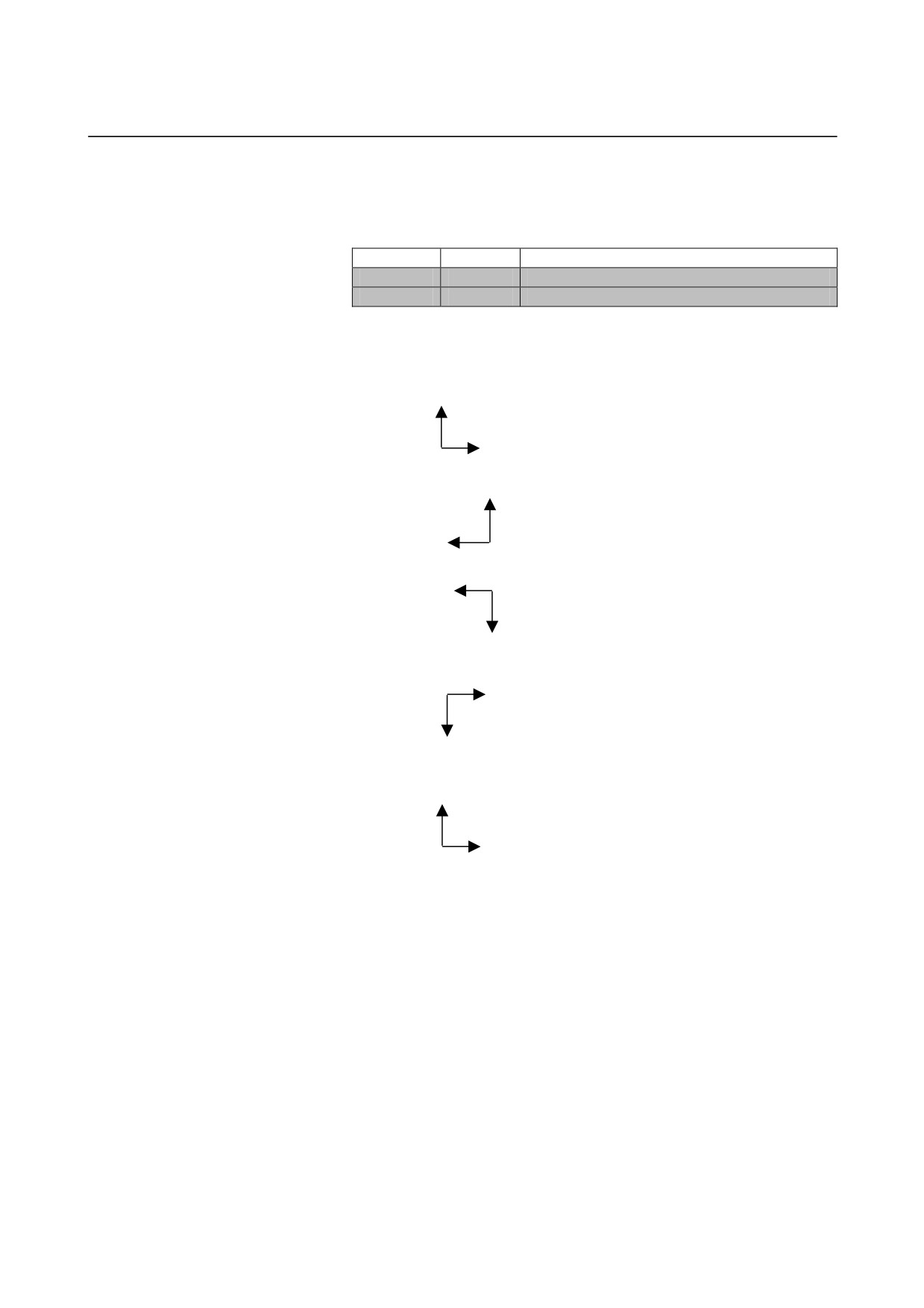
16
: Right hand coordinate, right =+Z and upper =+X
X
Z
17
: Right hand coordinate, right =-Z and upper =+X
X
Z
18
: Right hand coordinate, right =-Z and upper =-X
Z
X
19
: Right hand coordinate, right =+Z and upper =-X
Z
X
20
: Right hand coordinate, right =+X and upper =+Z
Z
X
- 836 -
B-63874EN/05
APPENDIX C.MANUAL GUIDE i SETUP METHOD
(7) Set following parameters for adapting rotate (Cs) axis motion to
workpiece coordinate. If no Cs axis or Animation option, it is
unnecessary to set.
In case of one Cs axis of main spindle
No.
Value
note
14717
→
Cs axis number
In case of two Cs axis with main and sub spindle
No.
Value
note
27301
→
Cs axis number of main spindle
27302
→
Cs axis number of sub spindle
switch Cs axis number by spindle selection
27312
xxxxxxx1
command for animation, “G1998 S__;” .
NOTE
14717 is used as working number for Cs axis.
(8) Set following parameters for adapting rotate axis motion, which
tilts tool head or table, to workpiece coordinate. If no such axis or
Animation option, it is unnecessary to set.
No.
Value
note
rotate axis number, which tilts tool head or
14718
→
table
(9) Set following parameters for Set up Guidance function. If no Set
up Guidance option, it is unnecessary to set.
No.
Value
note
Top number of variables for measurement
12381
10000*
condition
12382
10180*
Top number of variables for calibration
Top number of variables for measurement
12383
10300*
execution
Top number of variables for storing
12384
10500*
measurement result
Amount number of variables for storing
12385
699*
measurement result
12386
951*
Address of PMC R signal for measurement
12387
0*
Macro program number for tool select
Macro program number for measurement
12388
3600*
execution
* Settings described above is a sample. Set proper value according to
macro program made by MTB.
- 837 -
C.MANUAL GUIDE i SETUP METHOD APPENDIX
B-63874EN/05
(10) Set following parameters for Multi Path Lathe function. If no
Multi Path Lathe option, it is unnecessary to set.
No.
Value
note
14703#3
1
Process list editing is available
0:Softkey switches the display for each path
27400#0
→
1:Head select signal switches the display for
each path
0:Head#1 can not machine with spindle#2
14701#1
→
1:Head#1 can machine with spindle#2
0:Head#1 machines upper part of spindle#1
14701#2
→
1:Head#1 machines lower part of spindle#1
0:Head#1 machines upper part of spindle#2
14701#3
→
1:Head#1 machines lower part of spindle#2
0:Head#2 can not machine with spindle#1
27401#0
→
1:Head#2 can machine with spindle#1
0:Head#2 can not machine with spindle#2
27401#1
→
1:Head#2 can machine with spindle#2
0:Head#2 machines upper part of spindle#1
27401#2
→
1:Head#2 machines lower part of spindle#1
0:Head#2 machines upper part of spindle#2
27401#3
→
1:Head#2 machines lower part of spindle#2
0:Head#3 can not machine with spindle#1
27402#0
→
1:Head#3 can machine with spindle#1
0:Head#3 can not machine with spindle#2
27402#1
→
1:Head#3 can machine with spindle#2
0:Head#3 machines upper part of spindle#1
27402#2
→
1:Head#3 machines lower part of spindle#1
0:Head#3 machines upper part of spindle#2
27402#3
→
1:Head#3 machines lower part of spindle#2
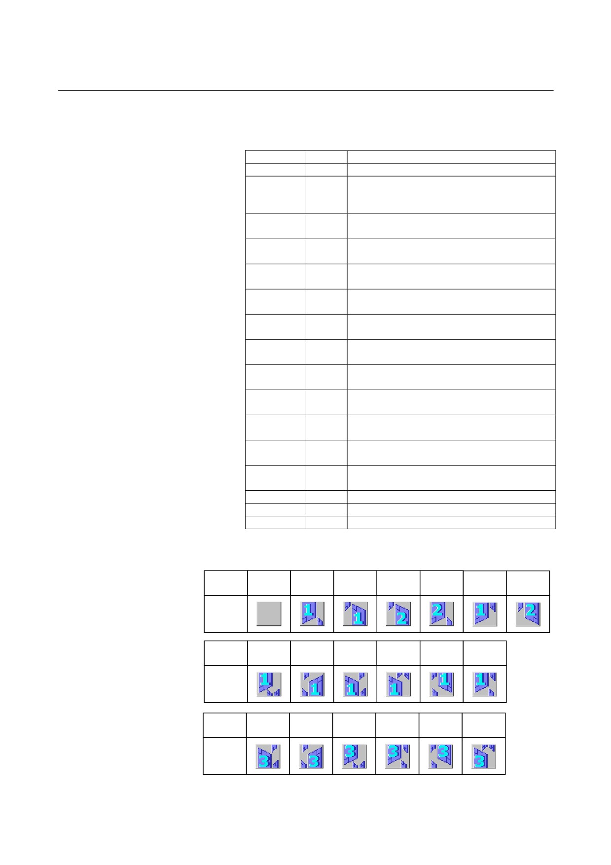
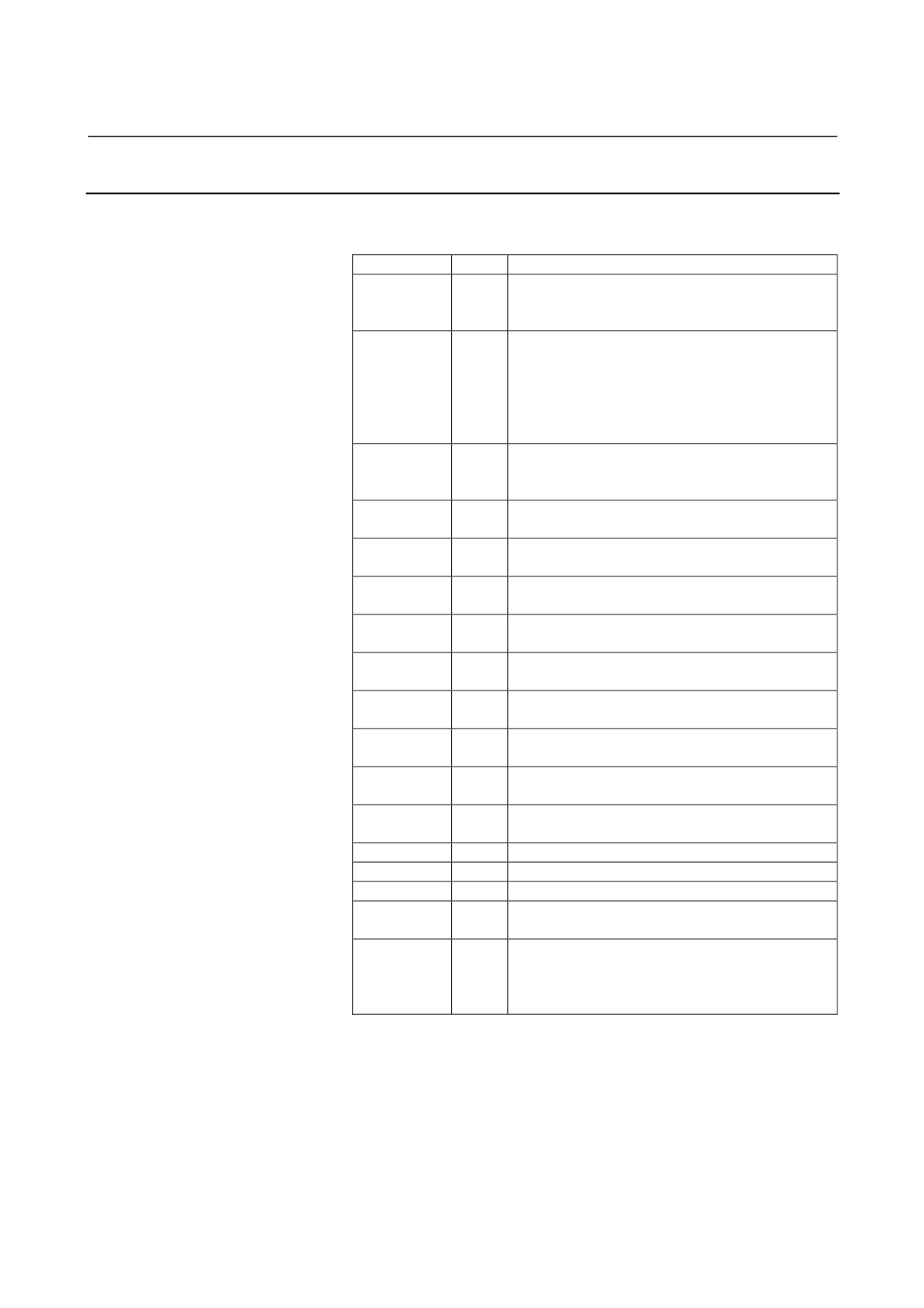
27410
Icon number for path 1 display
27411
Icon number for path 2 display
27412
Icon number for path 3 display
*
Icon number
Number
0
1
2
3
4
5
6
Icon
Number
10
11
12
13
14
15
Icon
Number
30
31
32
33
34
35
Icon
- 838 -
B-63874EN/05
APPENDIX C.MANUAL GUIDE i SETUP METHOD
C.4.2
Machining Center
(1) Set following parameters for MANUAL GUIDE i Basic function.
No.
Value
note
CNC ignores [HELP] key during displaying C
3103#3
1
executor screen in open CNC.
(It is necessary in Series 30i.)
[NEXT DISTANCE] display is available in single
block mode
It sumultaneously enables to look ahead 1 block.
3106#2
1
So if you stop the execution by SINGLE BLOCK
signal, then edit the next block and re-start, the
block before editting is executed.
No.3106#6, position display change for 3D
3206#6
1
conversion mode, is effective in MANUAL GUIDE i
screen
Servo wave display is not available
3112#0
0
(It is necessary in Series 30i.)
M02,M30,M99 are not regarded as the end of
3201#6
1
resister
SRAM size for application’s backup variables
8661
40
(40KB)
(It is necessary in Series 30i.)
SRAM size for application’s backup (23KB)
8662
23
(It is necessary in Series 30i.)
not switched to alarm screen automatically during
8650#1
1
displaying C executor screen
C executor transfer [RESET] key code to
8650#0
1
application
TV check is skipped during edit operation
8701#6
1
(It is necessary in Series 30i.)
Vacant value of P code variables can be read.
8701#4
1
(It is necessary in Series 30i.)
DRAM size for user program of C executor must
8781
0
be zero
(It is necessary in Series 30i.)
9000#0
0
Debug parameter for macro program must be zero
14700#7=0
0
Enable to run MANUAL GUIDE i
14794-14795
Assign function key for start MANUAL GUIDE i
P code number for MANUAL GUIDE i
9071
90
( in Series 30i with optional function)
Block number for dealing with Macro sentence
continuously in Execute Macro program for
9072
1
MANUAL GUIDE i.
( in Series 30i with optional function)
*
14794#0=1: [POS] key is assigned for start
#1=1: [PRG] key is assigned for start
#2=1: [OFS] key is assigned for start
#3=1: [SYS] key is assigned for start
#4=1: [MES] key is assigned for start
#5=1: [GRP] key is assigned for start
- 839 -
C.MANUAL GUIDE i SETUP METHOD APPENDIX
B-63874EN/05
14795#0=1: [CUSTOM](AUX screen) key is assigned for start
(No.8652#5 must be set to 1 in case macro screen does
not exist)
#1=1: [CUSTOM](MCR screen) key is assigned for start
(No.8652#6 must be set to 1 in case macro screen does not
exist)
#2=1: [CUSTOM](MENU screen) key is assigned for start
(No.8652#7 must be set to 1 in case macro screen does not
exist)
#3=1: Blank key is assigned for start
(No.8652#4 must be set to 1)
(2) Set following parameters for displaying load meter. Following
parameters depend on machining configuration. Refer to
Parameter Manual (B-63530EN) for detail.
No.
Value
note
1023
≠0
Servo axis number of control axis
2086
≠0
regular current parameter
2165
≠0
maximum value of amplifier current
3151-3158
≠0
Axis number to display load meter
(Note)
4127
≠0
Displayed value in maximum load
NOTE
In Series 30i, there are not the parameters from
No.3154 to No.3158.
(3) Set following parameters for optimizing cycle menu and icons of
Turning Cycle and Milling Cycle functions according to machine
configuration. In case of no above cycle options, it is unnecessary
to set.
No.
Value
note
14702#0
→
0:Vertical, 1:Horizontal
for icons
Xxxxxx01: 3 axes (XYZ) Machining Center
27003#1-#0
→
xxxxxx10: 5 axes (XYZCB) Machining Center
27103#7,#3-#0
0xxx0000
0xxx0000: Machining Center
* In case 27003= xxxxxx00 & 27103=0xxx0000, all of cycle menu is
displayed
* This parameter is available on BY40/04 and later.
NOTE
When the parameter No.27003 or No.27103 is set,
please sure to push [F] key on NOW LOADING
screen after Power ON. The necessary parameters
are set automatically. (When the necessary
parameters are set, the message of “NOW
SETTING PARAMETERS” is displayed on the left
below of NOW LOADING screen.)
- 840 -
B-63874EN/05
APPENDIX C.MANUAL GUIDE i SETUP METHOD
(4) Set following parameters for output of polar coordinate
interpolation command
(G12.1) and cylindrical interpolation
command (G7.1) in cycle motion. In case of no Cs axis or
Milling Cycle option, it is unnecessary to set.
No.
Value
note
0: G12.1/G13.1 are not output in cycle motion
on XC plane
2700#2
→
1: G12.1/G13.1 are automatically output in
cycle motion on XC plane
0: G7.1Cxx/G7.1C0 are not output in cycle
motion on ZC plane
2700#3
→
1: G7.1Cxx/G7.1C0 are automatically
output in cycle motion on ZC plane
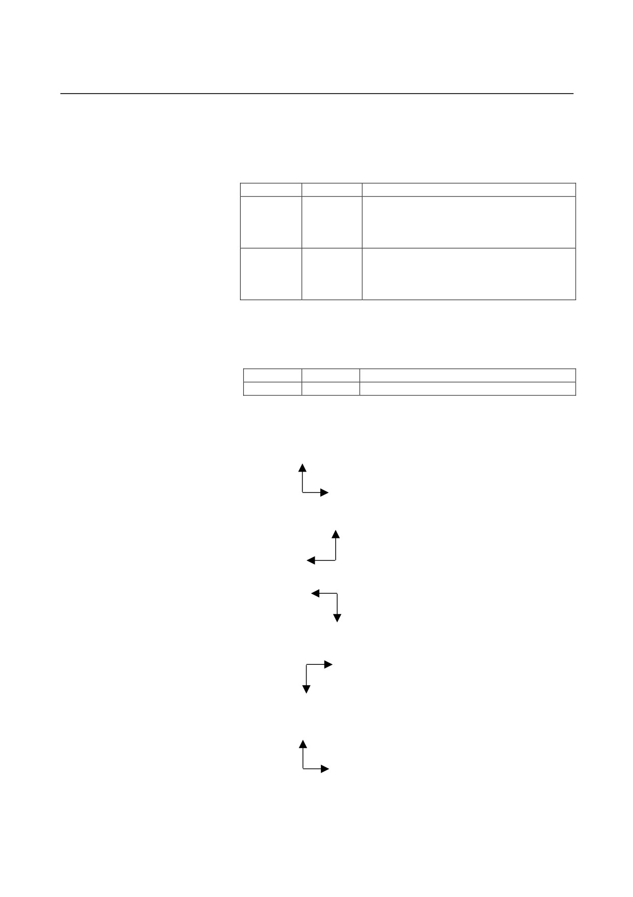
(5) Set following parameters for adapting tool motion to workpiece
coordinate in MANUAL GUIDE i Animation function. In case of
no Animation option, it is unnecessary to set.
No.
Value
note
14706
Workpiece coordinate
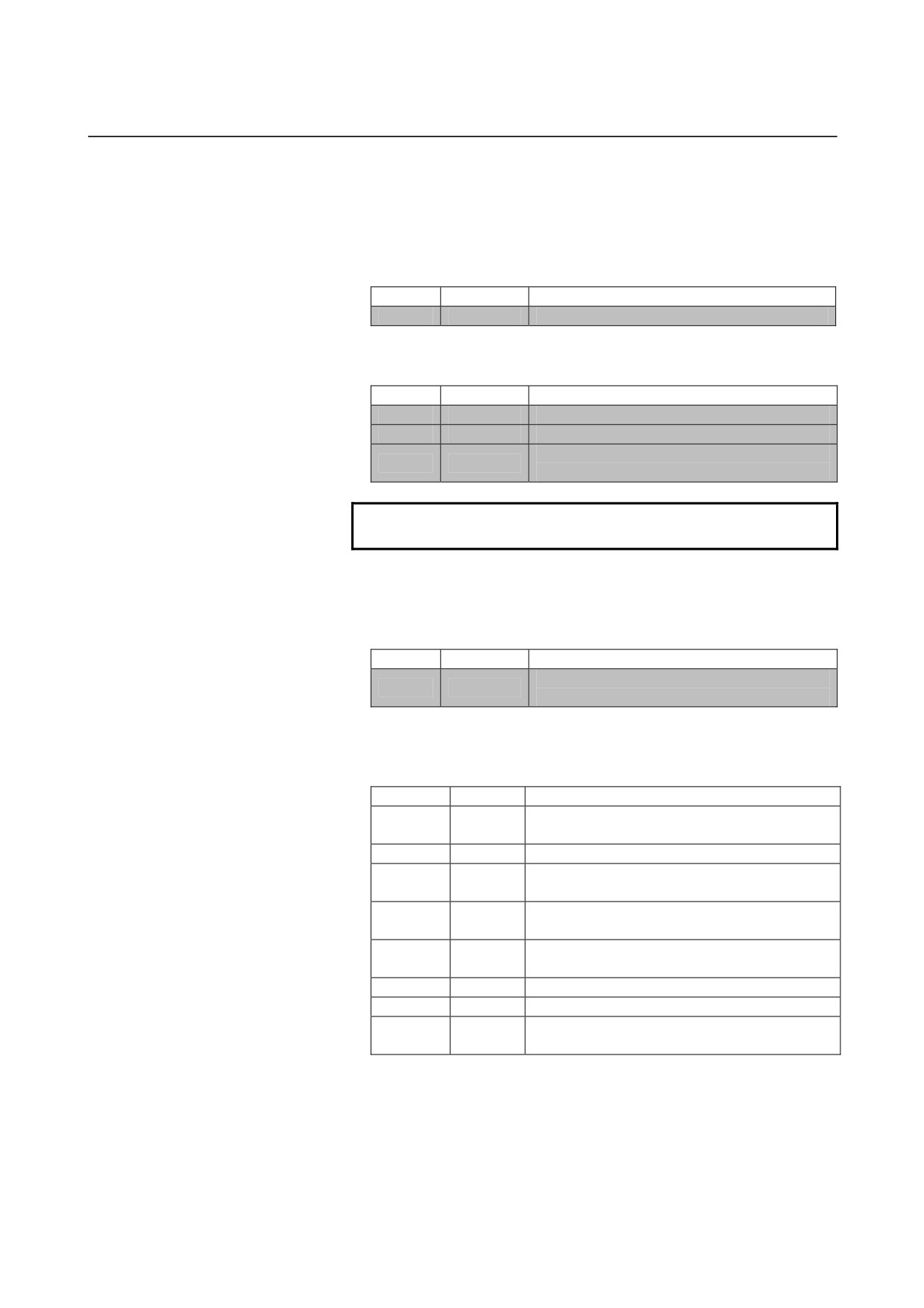
Setting value for 14706
16
: Right hand coordinate, right =+Z and upper =+X
X
Z
17
: Right hand coordinate, right =-Z and upper =+X
X
Z
18
: Right hand coordinate, right =-Z and upper =-X
Z
X
19
: Right hand coordinate, right =+Z and upper =-X
Z
X
20
: Right hand coordinate, right =+X and upper =+Z
Z
X
- 841 -
C.MANUAL GUIDE i SETUP METHOD APPENDIX
B-63874EN/05
(6) Set following parameters for adapting rotate (Cs) axis motion to
workpiece coordinate. If no Cs axis or Animation option, it is
unnecessary to set.
No.
Value
note
14717
→
Cs axis number
(7) Set following parameters for adapting rotate axis motion, which
tilts tool head or table, to workpiece coordinate. If no such axis or
Animation option, it is unnecessary to set.
No.
Value
note
Rotate axis number, which tilts tool head or
14718
→
table
(8) Set following parameters for Set up Guidance function. If no Set
up Guidance option, it is unnecessary to set.
No.
Value
note
Top number of variables for measurement
12381
10000*
condition
12382
10180*
Top number of variables for calibration
Top number of variables for measurement
12383
10300*
execution
Top number of variables for storing
12384
10500*
measurement result
Amount number of variables for storing
12385
699*
measurement result
12386
951*
Address of PMC R signal for measurement
12387
0*
Macro program number for tool select
Macro program number for measurement
12388
3600*
execution
* Settings described above is a sample. Set proper value according to
macro program made by MTB.
C.4.3 Other Machines
Refer to C.4.1 Lathe or C.4.2 Machining Center, which is closer to
your machine.
- 842 -
B-63874EN/05
APPENDIX C.MANUAL GUIDE i SETUP METHOD
C.5
M CODE OUTPUTED DURING CYCLE EXECUTING
Following M code is output in milling cycle
- M code for rigid tapping
- M code for clamping and unclamping rotate axis as “C”
C.5.1
M code for Rigid Tapping
(1) M code is output in following cycles in case that rigid tap is
specified and parameter No.5200#0 is zero.
G1002 (Tapping Cycle for Machining Center by live tool)
G1112 (Tapping Cycle for Lathe by live tool)
G1102 (Tapping Cycle for Lathe by rotating work)
(2) M code is output in following timing
G90
G00 X(x1) Y(y1) Z(I point)
G99
M29 S(spindle)*
G84 Z(depth) R(R point) P(dwell) F(feed)
X(x2) Y(y2)
X(x3) Y(y3)
G80
G00 Z(I point)
* M code value depends on parameter No.5210 and No.5212.
- 843 -
C.MANUAL GUIDE i SETUP METHOD APPENDIX
B-63874EN/05
C.5.2
M code for Clamping and Unclamping Rotate Axis as “C”
(1)
M code is automatically output in C axis, which position C axis
in the cycle motion.
In Hole Machining Cycles combined with following figures, C
axis clamping and unclamping M codes are automatically output.
a) C-axis hole on the polar coordinate plane (circle points):
G1572
b) C-axis hole on the polar coordinate plane (random points):
G1573
c) C-axis hole on the cylindrical surface (circle points): G1672
d) C-axis hole on the cylindrical surface
(random points):
G1673
In Grooving Cycles combined with following figures, C axis
clamping and unclamping M codes are automatically output.
e) X-axis groove on the polar coordinate plane: G1571
f)
Z-axis groove on the cylindrical surface: G1671
(2)
M code is output in following timing
In case of Hole Machining Cycles
G90
G17
Mb*
G00 X(x1) C(c1) Z(I point)
G99
G81 Z(depth) R(R point) F(feed) Ma*
Mb
X(x2) C(c2) Ma*
Mb
X(x3) C(c3) Ma*
Mb
G80
G00 Z(I point)
* Ma means C axis clamping M code, Mb means C axis
unclamping one.
M code value depends on parameter No.27005, No.27006,
No.27011 and No.27012
- 844 -
B-63874EN/05
APPENDIX C.MANUAL GUIDE i SETUP METHOD
In case of Grooving Cycles
Mb *
G17
G0 X 80. C0.
G0 Z2.
Ma *
G1Z-10.F100.
G1 X40. F100.
G1Z2.F100.
Mb *
G17
G0 X80. C120.
G0 Z2.
Ma *
G1Z-10.F100.
G1 X40. F100.
G1Z2.F100.
Mb *
* Ma means C axis clamping M code, Mb means C axis
unclamping one.
M code value depends on parameter No.27005, No.27006,
No.27011 and No.27012
- 845 -
C.MANUAL GUIDE i SETUP METHOD APPENDIX
B-63874EN/05
C.6 OPTIONAL FUNCTIONS AVAILABLE
Following optional functions are installed with MANUAL GUIDE i,
when a CNC is shipped.
C.6.1 Lathe (Series 16i/18i/21i)
Function
NO.
J734(*)
J872
MANUAL GUIDE i Basic
(S781)
J972
J973
J738#256K
J878
MANUAL GUIDE i Turning Cycle
(S783)
J930
J855
* User application on C executor is not available.
C.6.2 Machining Center (Series 16i/18i/21i)
Function
NO.
J734(*)
J872
J972
MANUAL GUIDE i Basic
(S781)
J973
J956
J738#256K
J890
MANUAL GUIDE i Milling Cycle
(S782)
J931
* User application on C executor is not available.
C.6.3 Lathe, Machining Center (Series 30i)
Function
NO.
J888
J873
J972
MANUAL GUIDE i Basic
(S781)
J973
J956
J760
J738#256K
J890
MANUAL GUIDE i Turning Cycle
(S783)
J855
J930
J890
MANUAL GUIDE i Milling Cycle
(S782)
J930
- 846 -
B-63874EN/05
INDEX
INDEX
AUTOMATIC SETTING OF INITIAL VALUE
<+>
DATA
298
[+INPUT] Soft Key
226, 231
AUTOMATIC SETTING OF INITIAL VALUES ON
<A>
THE INPUT DATA SCREEN
299
ACCESSING TOOL DATA BASE FUNCTION
259
AUTOMATIC TOOL DEFINITION BLOCK COPY ..299
Addition of Optional Block Skip for Each Path
<B>
Program Check
626
BACKGROUND EDITING
240
ADDRESS SETTING OF ROTATION AXIS
474
BASIC EDITING OPERATIONS OF PART
ALARMS
821
PROGRAM
55
ALL-IN-ONE SCREEN
9
BASIC OPERATIONS
604
ANIMATION FOR MULTI-PATH LATHE
585
Basic Operations
604
Arbitrary Figure Blocks for Contouring (XY Plane)
407
BASIC PARAMETERS
747
Arbitrary Figure Blocks for Contouring
BASIC SPECIFICATIONS
244
(YZ Plane, XC Plane, ZC Plane, XA Plane)
409
Basic Specifications
259
Arbitrary Figure Blocks for Emboss machining
BG EDITING
153
(XY Plane)
420
Arbitrary Figure Blocks for Emboss machining
<C>
(YZ Plane, XC Plane, ZC Plane, XA plane)
421
C AXIS CLAMPING M CODE OUTPUT
476
Arbitrary Figure Blocks for Facing (XY Plane)
380
CALCULATOR FUNCTION
294
Arbitrary Figure Blocks for Facing
CALCULATOR FUNCTION
295
(YZ Plane, XC Plane, ZC Plane, XA Plane)
381
CAUTIONS
322
Arbitrary Figure Blocks for Grooving (XY Plane)
463
C-AXIS GROOVING
465
Arbitrary Figure Blocks for Grooving
Cell
601
(YZ Plane, XC Plane, ZC Plane, XA Plane)
464
Changing by a soft-key
584
Arbitrary Figure Blocks for Pocketing (XY Plane)
439
Changing by a switch on a machine operator’s panel ...584
Arbitrary Figure Blocks for Pocketing
CHANGING CYCLE MACHINING AND FIGURE
(YZ Plane, XC Plane, ZC Plane, XA Plane)
441
DATA
83
Arbitrary Figure Blocks for Turning
516
Changing Screens for Each Path
584
ARBITRARY FIGURE COPY FUNCTIONS
140
CHANGING THE CURRENT POSITION DISPLAY. 150
ARBITRARY FIGURES FOR THE CYLINDRICAL
Changing the Program Number (ALTER key)
56
SURFACE (ZC PLANE)
118
CHANGING TOOL PRIORITY
658
ARBITRARY FIGURES FOR THE POLAR
CHANGING WORKPIECE COORDINATE DURING
COORDINATE INTERPOLATION PLANE
MACHINING SIMULATION
(XC PLANE)
107
(ANIMATION, TOOL PATH DRAWING)
188
Arbitrary Figures for the XY Plane
86
Checking by Animation
711, 740
ARBITRARY FIGURES FOR THE YZ PLANE
97
CHECKING OF THE PART PROGRAM
711, 740
ARBITRARY FIGURES FOR TURNING
[cnctitle] section
32
(ZX PLANE)
129
Comment
25, 29
Assign of Transfer
622
CONTOURING
382
Assign of Waiting
617
COORDINATE OF ARBITRARY FIGURES
ASSOCIATING TOOL NUMBERS WITH OFFSET
(XZ, ZC, ZY PLANE)
315
NUMBERS
635
i-1
INDEX
B-63874EN/05
COORDINATE SYSTEM SELECTION
DISPLAYED WARNING MESSAGES
666
COMMAND
313
DISPLAYING MACHINING TIME
COPY
58
(FOR Series 16i/18i/21i ONLY)
307
Copy Condition Input Screen
141
DISPLAYING MEASUREMENT RESULTS
152
Copying
261
DISPLAYING THE DRAWING-DURING-
Copying of a Cell
609
MACHINING WINDOW
152
CREATING MACHINING PROGRAMS
51
DISPLAYING THE MACHINING SIMULATION
Creating New Part Program
696, 719
WINDOW
152
CREATING OF PART PROGRAM
696, 719
Distinction between Main and Sub Spindle
477
Current Cell
601
DRAWING DURING MACHINING (TOOL PATH)..163
Current Position Display Part
595
<E>
CUT
58
EDITING A FIXED FORM FIGURE
Cutting Edge angle of Tool Data Base Function
255
SUBPROGRAM
267
<D>
EDITING A FREE FORM FIGURE
Data Displayed in the Program List
301
SUBPROGRAM
264
Data Format
286
EDITING CYCLE MACHINING OPERATIONS
66
DATA HANDLED DURING MACHINING
EDITING IN A PROGRAM LIST
52
SIMULATION (FOR Series 30i)
185
EDITING MACHINING PROGRAMS
48
DEALING OF THE PART PROGRAM WITH
EDITING OF FREE FIGURE AND FIXED FORM
UNFITTED TO PROCESS LIST FORM
629
FIGURE OF SUBPROGRAM FORM
263
DELETE
59
Editing of Tool Name
254
Deleting a Block (DELETE key)
56
EDITING OPEARTIONS
605
Deleting a Fixed Form Sentence
239
EDITING WITH THE MACHINING PROGRAM
Deleting a Word (DELETE key)
56
LIST
149
Deletion of a Cell
607
EMBOSS MACHINING
410
Deletion of Optional Block Skip for Each Path
End
600
Program Check
628
End Command of Reflection
218
DETAILED DESCRIPTIONS ABOUT ENTERING
ENDING BACKGROUND EDITING
242
ARBITRARY FIGURES
84
Entering a Word (INSERT key)
55
DETAILS
592
ENTERING ARBITRARY FIGURE DATA FOR
DISABLE WARNING MESSAGE
638, 647
CYCLE MACHINING
78
DISPLAY CONTENTS
601
Entering blank form data
697, 720
DISPLAY DATA ini FILE FORMAT
29
Entering by fixed form sentence menu
Display Life States of Group
663
................................ 698, 707, 710, 721, 731, 736, 739
DISPLAY MACHINING TIME
311
Entering C-axis drilling cycle block
708
DISPLAY OF ARBITRARY FIGURES OF M98
Entering C-axis Drilling Process
708
SUBPROGRAMS
305
ENTERING CONTOUR PROGRAMS
81
DISPLAY OF GROUP NUMBER LIST
663
ENTERING CYCLE MACHINING DATA
71
Display Position of Each Path
593
Entering drilling cycle block
737
DISPLAY TOOL MANAGEMENT DATA OF CNC
Entering Drilling Process
737
STANDARD SCREEN
675
Entering figure for outer finishing
706
DISPLAYED OFFSET TYPES
Entering figure for outer finishing cycle block
705
(SET BY THE MACHINE TOOL BUILDER)
674
Entering figure for outer roughing
701
Displayed Warning Messages
651, 653
Entering figure for outer wall contouring (rough)
723
i-2
B-63874EN/05
INDEX
Entering figure for pocket bottom finishing
733
Execution Operations in Machining Simulation
Entering figure for pocket roughing
726
(Tool Path)
170, 182
Entering figure for pocket side finishing
735
EXPLANATORY NOTES
685
ENTERING FIXED FORM FIGURE DATA FOR
<F>
CYCLE MACHINING
75
FACING
370
Entering hole position block
709, 738
Figure after Arbitrary Figure Copy Execution
147
Entering in ISO-code form directly
Figure Blocks for C-axis Grooving and A-axis
................................ 698, 707, 710, 721, 731, 736, 739
Grooving
467
Entering of the Fixed Form Sentence for Milling
File Format Allowed for Memory Card Input/Output ...283
Machining
694
Fixed Form Figure Blocks for Contouring (XY Plane) .403
Entering of Tool Data
254
Fixed Form Figure Blocks for Contouring
Entering Outer Finishing Cycle Machining Process
705
(YZ Plane, XC Plane)
406
Entering outer roughing cycle block
699
Fixed Form Figure Blocks for Facing (XY Plane)
376
Entering Outer Roughing Process
699
Fixed Form Figure Blocks for Facing
Entering outer wall contouring (rough) cycle block
722
(YZ Plane, XC Plane)
379
Entering Outer Wall Contouring Process
722
Fixed Form Figure Blocks for Grooving (XY Plane)
457
Entering Pocket Bottom and Side Finishing Process
732
Fixed Form Figure Blocks for Grooving
Entering pocket bottom finishing cycle block
732
(YZ Plane, XC Plane)
462
Entering pocket roughing cycle block
724
Fixed Form Figure Blocks for Pocketing (XY Plane) ...435
Entering Pocket Roughing Process
724
Fixed Form Figure Blocks for Pocketing
Entering pocket side finishing cycle block
734
(YZ Plane, XC Plane)
438
Entering releasing motion blocks in ISO-code form
706
Fixed Form Figure Blocks for Threading
564
ENTERING THE END COMMAND
83
Fixed Form Figure Blocks for Turning Grooving
544
Entering the Fixed Form Sentence for Milling
717
FIXED FORM SENTENCE INSERTION
64
Entering the Fixed Form Sentence for Turning
FORMAT
631
Machining
693
Format of Fixed Form Sentences
289
ENTERING THE START COMMAND
67
FORMAT OF MACHINING TIME DATA
308
Entering Tool Changing and Spindle Rotating Blocks
[frame_functionkey] section
36
for C-axis Drilling
707
[frame_mainscreen] section
31
Entering Tool Changing and Spindle Rotating Blocks
[frame_mdikey] section
34
for Drill
736
FULL-SCREEN DISPLAY
22
Entering Tool Changing and Spindle Rotating Blocks
Function
217
for Finishing Flat End Mill
731
[functionkey] section
37
Entering Tool Changing and Spindle Rotating Blocks
FUNCTIONS OPERATING DIFFERENTLY
for Roughing Flat End Mill
721
BETWEEN MACHINING SIMULATION AND
Entering Tool Changing and Spindle Rotating Blocks
AUTOMATIC OPERATION (FOR Series 30i)
186
for Turning Machining
698
Functions That Can Be Used for Machining
Entering Tool Changing and Spindle Rotation Blocks
Simulation (Milling System)
187
for Outer Finishing in ISO-code Form
704
Functions That Cannot Be Used for Machining
Executing Arbitrary Figure Copy Operation
145
Simulation
187
Execution Operations in Machining Simulation
(Animated)
174
<G>
Execution Operations in Machining Simulation
GROOVING
442
(Animated)
183
GROUP NUMBER LIST DISPLAY
661
i-3
INDEX
B-63874EN/05
<H>
Lathe, Machining Center (Series 30i)
846
HANDLING A PROGRAM LARGER THAN THE
LIFE MANAGEMENT DATA LIST SCREEN
669
MAXIMUM ALLOWABLE SIZE
292
<M>
HANDLING LARGE PROGRAMS
290
M code for Clamping and Unclamping Rotate Axis
HARDWARE
827
as “C”
844
HELP SCREEN
275
M code for Rigid Tapping
843
HOLE MACHINING (WORKPIECE ROTATION)
483
M CODE OUTPUTED DURING CYCLE
HOLE MACHINING BY MILLING
335
EXECUTING
843
HOLE MACHINING BY TURNING
Machine Configuration Setting
582
(WITH THE TOOL ROTATED)
363
MACHINING CENTER
712
Hole Machining Type Block
335
Machining Center
839
Hole Position Block
Machining Center (Series 16i/18i/21i)
829, 846
(XA Plane and Cylindrical Surface)
362
MACHINING PROGRAM FORMAT
46
Hole Position Block (XC Plane and End Face)
360
MACHINING PROGRAM WINDOW AND EIDITNG 49
Hole Position Block (XY Plane)
351
MACHINING SIMULATION
316
Hole Position Block (YZ Plane)
359
MACHINING SIMULATION (ANIMATED)
Hole Position Block
(FOR Series 16i/18i/21i)
172
(ZC Plane and Cylindrical Surface)
362
MACHINING SIMULATION (ANIMATED)
How to Finish
592
(FOR Series 30i)
183
HOW TO SELECT PATH
596
Machining Simulation (Animation)
586
How to Start
592
MACHINING SIMULATION (TOOL PATH)
<I>
(FOR Series 16i/18i/21i)
168
INCREMENTAL PROGRAMMING
85
MACHINING SIMULATION (TOOL PATH)
Information to be passed when a button is pressed
38
(FOR Series 30i)
177
INHIBITION OF EDITING TOOL MANAGEMENT
MACHINING SIMULATION AND DRAWING
DATA AT CNC STANDARD SCREEN
681
DURING MACHINING
161
Initialization
262
MACHINING SIMULATION FOR EACH PATH
587
Initialization of All Tool Data
262
Machining Type Blocks for C-axis Grooving
465
Initialization to Standard Fixed Form Sentences
239
Machining Type Blocks for Contouring
382
Initializing of Tool Data
256
Machining Type Blocks for Emboss machining
410
[INP.C.] Soft Key
232
Machining Type Blocks for Facing
370
Input Fixed Form Sentences
289
Machining Type Blocks for Grooving
442
Insertion of a Cell
606
Machining Type Blocks for Hole Machining
(Workpiece Rotation)
483
<K>
Machining Type Blocks for Hole Machining by
Key
25, 30
Turning (with the Tool Rotated)
363
KEY-IN PASTE
60
Machining Type Blocks for Pocketing
422
<L>
Machining Type Blocks for Threading
559
LATHE
686
Machining Type Blocks for Turning
488
Lathe
833
Machining Type Blocks for Turning Grooving
517
Lathe (Series 16i/18i/21i)
828, 846
MAGAZINE DATA SCREENS
Lathe or Machining Center (Series 30i)
830
(MAGAZINE 1 TO 4)
650
Lathe with Compound Machining Function (Series
MAIN FEATURES OF MANUAL GUIDE i
44
16i/18i/21i)
831
MANUAL GUIDE i SETUP METHOD
826
i-4
B-63874EN/05
INDEX
MANUAL GUIDE i SIMULATOR FOR THE
<O>
PERSONAL COMPUTER
16
OPERATING ENVIRONMENT
17
MANUAL MEASUREMENT
321
Operating Environment
17
M-CODE MENU
62
OPERATING THE NC PROGRAM CONVERSION
[mdikey] section
35
FUNCTION
246
[MEASUR] Soft Key
225
Operation
659
[MEASUR] Soft Key
230
OPERATION
676
MEASUREMENT CYCLE
321
OPERATION FOR INSERTING MACHINING
MEASUREMENT RESULT DISPLAY SCREEN
321
TIME
309
MEMORY CARD I/O SCREEN
304
Operations
681
Memory Card Input Operation for Part Program
282
Operations Added for the Program List Screen
302
Memory Card Input Operation for Tool Data
286
OPERATIONS DURING BACKGROUND EDITING 242
MEMORY CARD INPUT/OUTPUT FUNCTION
277
Operations in the “END” Menu
710, 739
MEMORY CARD INPUT/OUTPUT OF FIXED FORM
OPERATIONS IN THE MANUAL MODE
SENTENCES
287
(HANDLE AND JOG)
160
MEMORY CARD INPUT/OUTPUT OF PART
OPERATIONS IN THE MDI MODE
158
PROGRAM
278
OPERATIONS IN THE MEM MODE
148
MEMORY CARD INPUT/OUTPUT OF TOOL DATA284
Operations of “START” Menu
697, 720
Memory Card Input/Output Screen of Fixed Form
OPERATIONS OF MULTI-PATH LATHE
584
Sentences
287
OPTIONAL FUNCTIONS AVAILABLE
846
Memory Card Input/Output Screen of Part Program
278
Other Machines
842
Memory Card Input/Output Screen of Tool Data
284
Other Machines (Series 16i/18i/21i)
831
Memory Card Output Operation for Part Program
279
Other Machines (Series 30i)
832
Memory Card Output Operation for Tool Data
285
Other Parameters
772, 820
METHOD OF INSTALLATION
18
OTHERS
589, 596, 631, 678
MILLING
325
Output Fixed Form Sentences
288
MODAL DISPLAY OF OFFSET TYPES
672
OUTPUT OF AN ARBITRARY FIGURE AS A
Modification of Process Name
614
SUBPROGRAM
304
Modifying a Block (ALTER key)
56
OVERVIEW OF THE PROCEDURE
43
Modifying a Fixed Form Sentence
238
OVERVIEW OF THIS MANUAL
3
Modifying a Word (ALTER key)
55
<P>
Modifying the Numeric Value of a Word (ALTER key) 55
[P TYPE] Soft-key
156
Moving of a Cell
611
PARAMETER
23
MULTI-PATH LATHE APPLICATION
581
Parameter
598
<N>
Parameter for Machining Simulation (Animated)
816
NC PROGRAM CONVERSION
153
Parameter for Turning and Grooving Cycles
801
NC PROGRAM CONVERSION FUNCTION
243
PARAMETER SETTING
833
NEXT-BLOCK DISPLAY FUNCTION
154
PARAMETERS
743
Note
832
Parameters Common to Turning Cycles
795
NOTES
24, 644
Parameters for Contouring Cycles
784
Notes on Arbitrary Figure Copy Operation
147
Parameters for Facing Cycles
783
NOTES ON CREATING PROGRAMS
13
Parameters for Grooving Cycles
792
Notes on Machining Simulation
175
Parameters for Icon of Path Number Display
819
Parameters for Machining Simulation (Animated)
804
i-5