FANUC MANUAL GUIDE i. OPERATOR’S MANUAL - page 28
A.PARAMETERS
APPENDIX
B-63874EN/05
A.3.5
Parameters for Grooving Cycles
These parameters are for the settings for grooving cycles.
#7
#6
#5
#4
#3
#2
#1
#0
27080
GR2
GR1
GR0
GR0
0 :
During roughing and bottom finishing, in-feed in the cutter radius
direction is performed with a uniform depth of cut.
(A uniform depth is the calculated depth automatically.)
1 :
During roughing and bottom finishing, in-feed in the cutter radius
direction is performed with [CUT DEPTH OF RADIUS].
GR1
0 :
During roughing and bottom finishing, in-feed in the tool axis
direction is performed with a uniform depth of cut.
(A uniform depth is the calculated depth automatically.)
1 :
During roughing and bottom finishing, in-feed in the tool axis
direction is performed with [CUT DEPTH OF AXIS].
GR2
0 :
During roughing and bottom finishing, tool retracts to the top
workpiece surface plus the clearance..
1 :
During roughing and bottom finishing, the tool retracts to the position
of the machining surface plus the clearance.
#7
#6
#5
#4
#3
#2
#1
#0
27081
GF4
GF3
GF2
GF1
GF0
GF0
0 :
During in-feed in side finishing and chamfering, the tool moves by
retracting to the height of the top workpiece surface plus the
clearance.
1 :
During in-feed in side finishing and chamfering, the tool moves by
retracting to the height of the machining surface plus the clearance.
GF1
0 :
In side finishing and chamfering, the tool moves at a hollow by
retracting to the height of the top workpiece surface plus the
clearance.
1 :
In side finishing and chamfering, the tool moves at a hollow by
retracting to the height of the machining surface plus the clearance.
GF2
0 :
In side finishing and chamfering, the tool moves at an opening by
retracting to the height of the top workpiece surface plus the
clearance.
1 :
In side finishing and chamfering, the tool moves at an opening by
retracting to the height of the machining surface plus the clearance.
GF3
0 :
In side finishing, NC does not perform cutter compensation.
1 :
In side finishing, NC performs cutter compensation.
Remark) Tool path is not calculated with Cutter compensation in
inside, but G41 or G42 is outputted directly.
GF4
0 :
The system performs an interference check.
1 :
The system does not perform an interference check.
- 792 -
B-63874EN/05
APPENDIX
A.PARAMETERS
27085
GOFSW
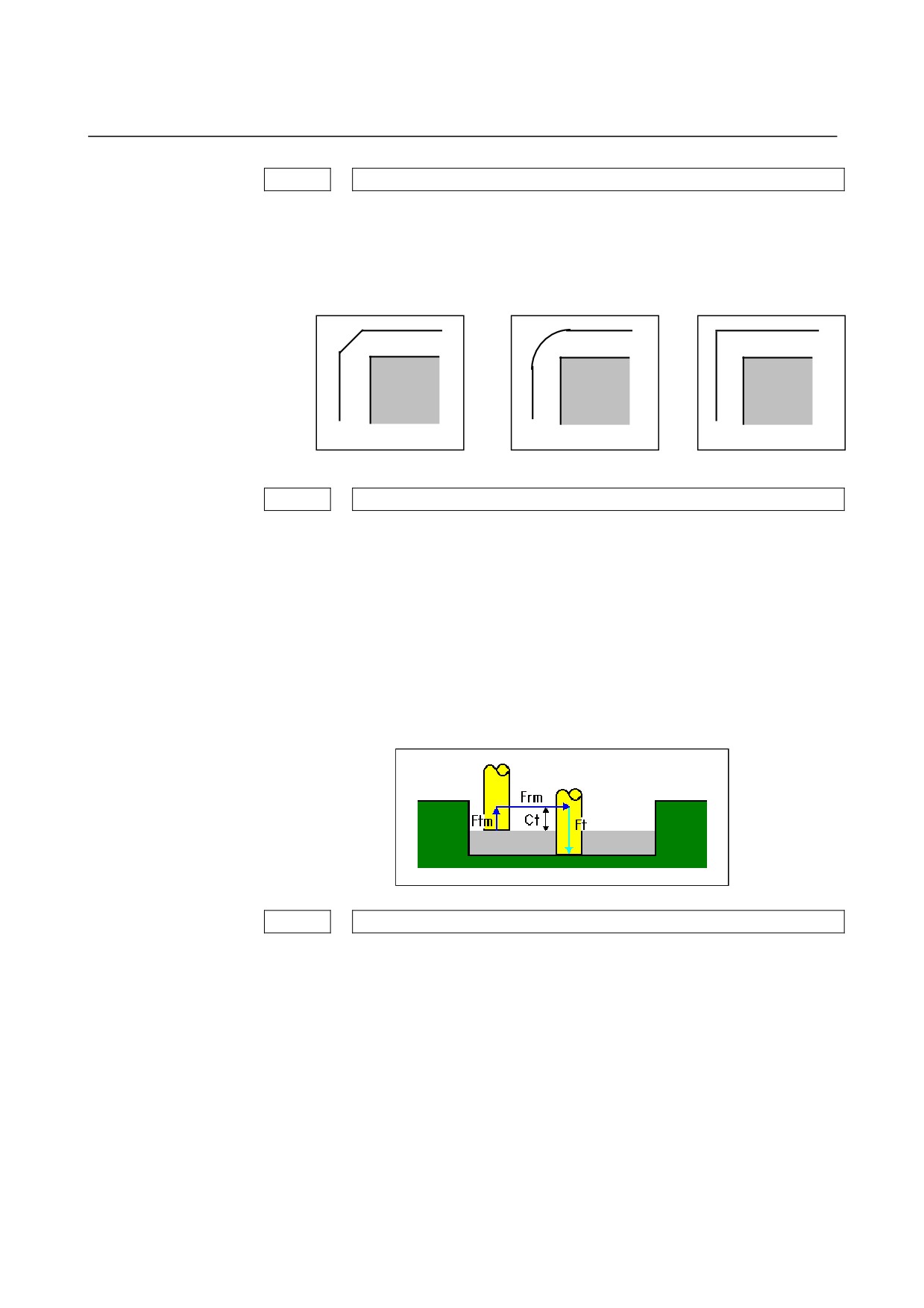
GOFSW : Offset method for groove finishing paths.
= 0 : Corner cut interpolation.
= 1 : Circular interpolation.
= 2 : Extended straight line.
0
1
2
27086
GMVFR
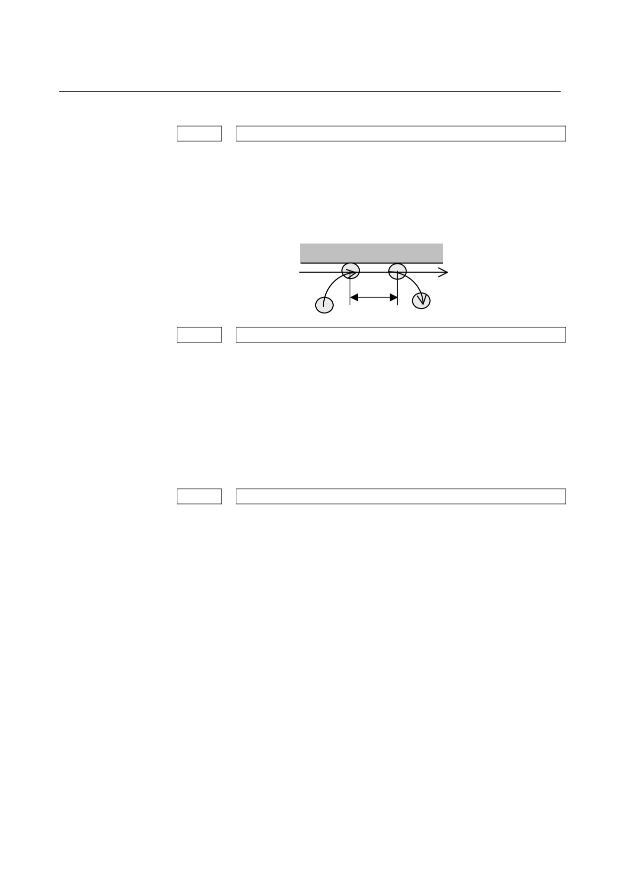
GMVFR : Feedrate during movement in the cutter radius direction in grooving
for feed per minute.
If 0 is set, the feedrate is assumed Rapid traverse feedrate.
Unit of data:
For metric input (0000#2=0) : 1(mm/min)
For inch input (0000#2=1) : 0.01(inch/min)
Remark) Feedrate during movement in the cutter radius direction is
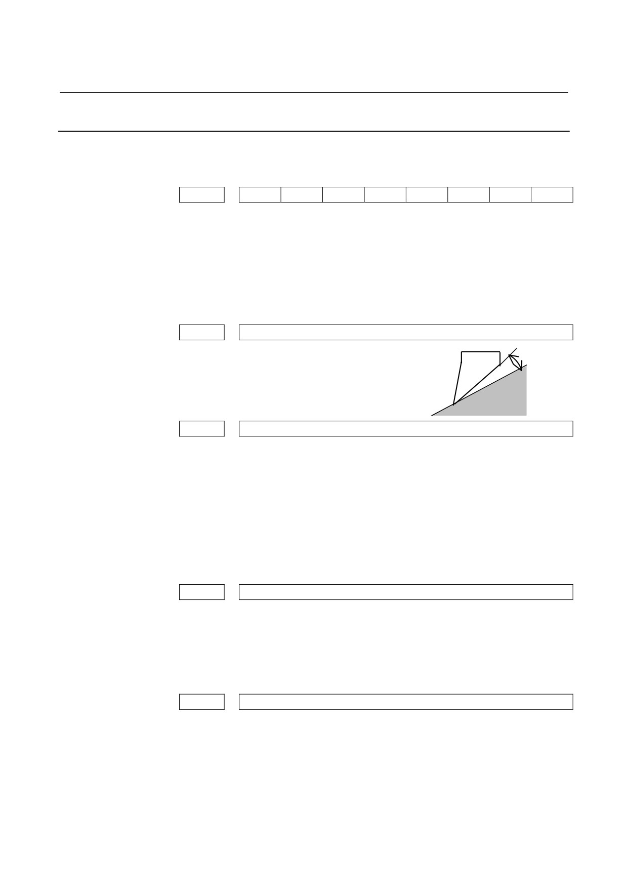
‘Frm’ as the following illustration.
27087
GMVFT
GMVFT : Feedrate during movement in the tool axis direction in contouring for
feed per minute.
If 0 is set, the feedrate is assumed Rapid traverse feedrate.
Unit of data:
For metric input (0000#2=0) : 1(mm/min)
For inch input (0000#2=1) : 0.01(inch/min)
Remark) Feedrate during movement in the tool axis direction is ‘Ftm’
as the above illustration.
- 793 -
A.PARAMETERS
APPENDIX
B-63874EN/05
27088
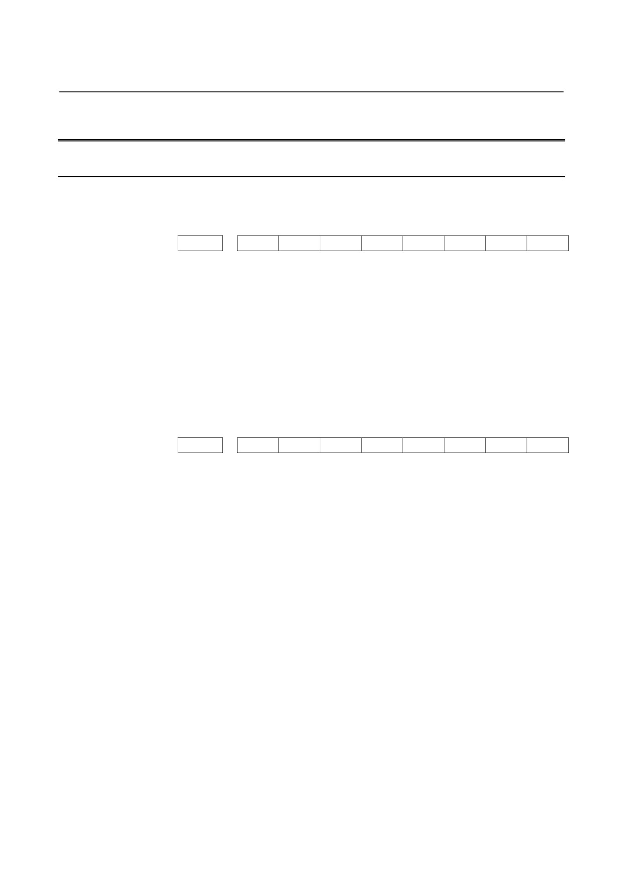
GVOVL
GVOVL : Amount of overlapping for an approach/escape during side finishing
and chamfering.
Unit of data :
For metric input (0000#2=0) : 0.001(mm)
For inch input (0000#2=1) : 0.0001(inch)
GVOVL
27089
GMVFR
GMVFR :
Feedrate during movement in the cutter radius direction in grooving
for feed per revolution.
If 0 is set, the feedrate is assumed Rapid traverse feedrate.
Unit of data:
For metric input (0000#2=0) : 0.0001(mm/rev)
For inch input (0000#2=1) : 0.000001(inch/rev)
Remark) Refer to No.27086.
27090
GMVFT
GMVFT :
Feedrate during movement in the tool axis direction in contouring for
feed per revolution.
If 0 is set, the feedrate is assumed Rapid traverse feedrate.
Unit of data:
For metric input (0000#2=0) : 0.0001(mm/rev)
For inch input (0000#2=1) : 0.000001(inch/rev)
Remark) Refer to No.27087.
- 794 -
B-63874EN/05
APPENDIX
A.PARAMETERS
A.4
PARAMETERS FOR TURNING CYCLE OPTIONS
A.4.1
Parameters Common to Turning Cycles
These parameters are used for settings common to Turning cycles.
#7
#6
#5
#4
#3
#2
#1
#0
27100
TC4
TC1
TC0
TC0
0 :
The input item of [CUT DEPTH DIRECTION] is not displayed.
1 :
The input item of [CUT DEPTH DIRECTION] is displayed.
TC1
0 :
The input item of
[POCKET CUTTING] and
[OVERHANG
CUTTING] are not displayed.
1 :
The input item of
[POCKET CUTTING] and
[OVERHANG
CUTTING] are displayed.
TC4
0 :
The tab of [FACE POSIT] for end face position is not displayed.
1 :
The tab of [FACE POSIT] for end face position is displayed.
Remark) Refer to “III-2.5 Rear End Facing by Turning”.
#7
#6
#5
#4
#3
#2
#1
#0
27102
ESC
MDL
LOC
TYP
TLG
TLG
0 :
In Turning cycle menu, the tab of [TOOL COND.] is not displayed.
1 :
In Turning cycle menu, the tab of [TOOL COND.] is displayed.
TYP
0 :
When the data input window for a turning figure block is opened for
modification, the item "FIGURE TYPE" displays all figure types.
1 :
When the data input window for a turning figure block is opened for
modification, the item "FIGURE TYPE" displays only the figure type
that is applicable to the immediately preceding machining process.
LOC
0 :
The turning cycle menu lists "HOLE MACHINING", "TURNING",
"TURNING GROOVING", and "THREADING" in this order
1 :
The turning cycle menu lists "TURNING", "TURNING GROOVING",
"THREADING", and "HOLE MACHINING" in this order.
MDL
0 :
In Turning cycles, after completing the whole cycle motions, the
modal will be returned to the state of beginning cycle.
1 :
In Turning cycles, after completing the whole cycle motions, the
modal will not be returned to the state of beginning cycle.
ESC
0 :
In Turning cycles, after completing the whole cycle motions, the tool
will go back to the point where machining cycle started.
1 :
In Turning cycles, after completing the whole cycle motions, the tool
will not go back to the point where machining cycle started.
- 795 -
A.PARAMETERS
APPENDIX
B-63874EN/05
#7
#6
#5
#4
#3
#2
#1
#0
27103
LT7
LT3
LT2
LT1
LT0
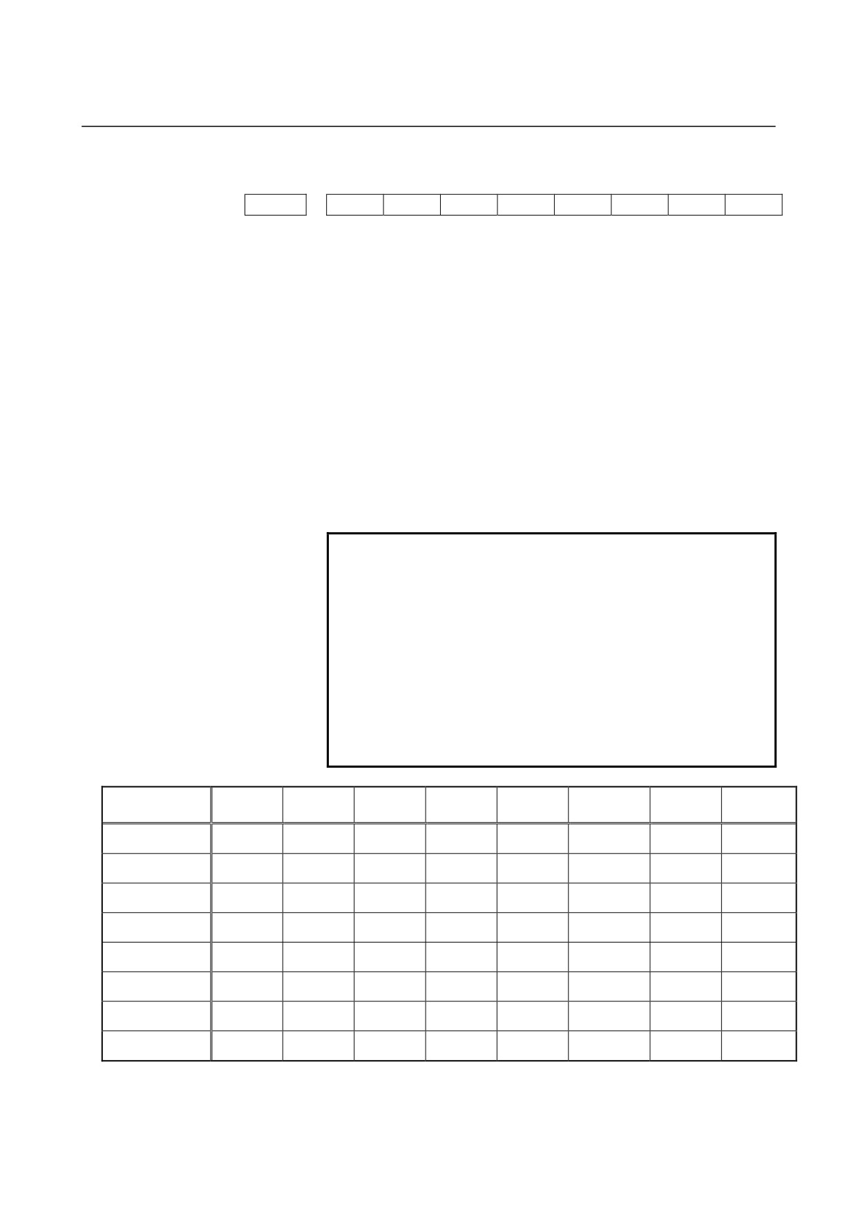
By setting this parameter, the optimum cycle menus can be displayed
on the screen. Please set
1 bit only according to the machine
configuration.
LT0
1 :
Lathe - X/Z-axis
LT1
1 :
Lathe - X/Z/C-axis
LT2
1 :
Lathe - X/Z/C/Y-axis
LT3
1 :
Lathe -X/Z/C/Y/B-axis (B-axis : Tool tilting axis)
Remarks) If over two of LT0 to LT3 are set, larger number bit takes
priority.
LT7
1 :
Lathe - Lathe with sub spindle
Remarks) This LT7 is used together with LT0 to LT3.
NOTE
1 When the parameter No.27103 is set, please sure
to push [F] key on NOW LOADING screen after
Power ON. The necessary parameters are set
automatically.
(When the necessary parameters
are set, the message of
“NOW SETTING
PARAMETERS” is displayed on the left side of
NOW LOADING screen.)
2 By setting the parameter No.27103, the following
parameters related to display are set
autoimatically.
No.14702#1
No.27000#1
No.27000#4
No.27100#4
No.27000#6
No.27001#0,#1
No.27004#0
No.27004#1
Spindl select
Hole select
Face pos-M
Face pos-T
Coord conv
Rot. axis nam
Menu 1
Menu 2
No.27103 #0=1
0
0
0
0
1
0
0
0
No.27103 #7=0
No.27103 #1=1
0
1
0
0
1
0
0
1
No.27103 #7=0
No.27103 #2=1
0
1
0
0
1
0
0
0
No.27103 #7=0
No.27103 #3=1
0
1
0
0
0
0
0
0
No.27103 #7=0
No.27103 #0=1
1
0
0
1
1
0
0
0
No.27103 #7=1
No.27103 #1=1
1
1
1
1
1
1
0
1
No.27103 #7=1
No.27103 #2=1
1
1
1
1
1
1
0
0
No.27103 #7=1
No.27103 #3=1
1
1
1
1
0
1
0
0
No.27103 #7=1
- 796 -
B-63874EN/05
APPENDIX
A.PARAMETERS
A.4.2 Parameters for Turning Cycle Machining
These parameters are for the settings for turning cycles.
#7
#6
#5
#4
#3
#2
#1
#0
27120
BLN
BLN
0 : When the tool advances in the cutting direction, the excessive amount
of travel of the tool is nose radius R if the attribute of the figure across
which the tool moves is the blank element.
1 : When the tool advances in the cutting direction, the excessive amount
of travel of the tool is [clearance + nose radius R (×2) if the attribute
of the figure across which the tool moves is the blank element
(conventional specifications).
27125
PTANG
PTANG : Cutting edge protection angle.
PTANG
Unit of data :
1 deg
27126
DCLMP
DCLMP :
clamping value of ‘CUT DEPTH’ in Turning, Turning grooving and
Threading
Unit of data :
For metric input (0000#2=0) : 0.001 mm
For inch input (0000#2=1) : 0.0001 inch
When DCLMP = 0, the depth-of-cut clamping value is assumed to be
one-tenth of a specified depth of cut.
27128
ESCPCLMP
ESCPCLMP :
Minimum clump value of ESCAPE AMOUNT for Turning Cycle.
Unit of data:
For metric input (0000#2=0) : 0.001(mm)
For inch input (0000#2=1) : 0.0001(inch)
27129
XAXSCLMP
XAXSCLMP :
Minimum clump value of X-AXIS CLEARANCE for Turning Cycle.
Unit of data:
For metric input (0000#2=0) : 0.001(mm)
For inch input (0000#2=1) : 0.0001(inch)
- 797 -
A.PARAMETERS
APPENDIX
B-63874EN/05
27130
ZAXSCLMP
ZAXSCLMP : Minimum clump value of Z-AXIS CLEARANCE for Turning Cycle.
Unit of data:
For metric input (0000#2=0) : 0.001(mm)
For inch input (0000#2=1) : 0.0001(inch)
A.4.3
Parameters for Threading Cycles
These parameters are for the settings for threading cycles.
27145
TDMIN
TDMIN :
Minimum depth of cut during threading.
Unit of data :
For metric input (0000#2=0) : 0.001 mm
For inch input (0000#2=1) : 0.0001 inch
27150
TGNOUT
TGNOUT :
Thread height factor for general-purpose threads
(for outside
diameters). The value 0 is regards as 0.6495.
Unit of data :
0.0001
NOTE
No.27150 is used to calculate [THREAD DEPTH]
in general-purpose threads (for outside diameters).
The formula is as follows.
(Thread Depth for Outside) = (No.27150) × (Lead)
27151
TGNIN
TGNIN :
Thread height factor for general-purpose threads (for inside diameters).
The value 0 is regards as 0.6495.
Unit of data :
0.0001
NOTE
No.27151 is used to calculate [THREAD DEPTH]
in general-purpose threads (for inside diameters).
The formula is as follows.
(Thread Depth for Inside) = (No.27151) × (Lead)
- 798 -

B-63874EN/05
APPENDIX
A.PARAMETERS
27152
TMTOUT
TMTOUT :
Thread height factor for metric and unified threads
(for outside
diameters). The value 0 is regards as 0.6495.
Unit of data :
0.0001
NOTE
1 No.27152 is used to calculate [THREAD DEPTH]
in metric threads (for outside diameters).
The formula is as follows.
(Thread Depth for Outside) = (No.27152) × (Lead)
2 No.27152 is used to calculate [THREAD DEPTH]
in unified threads (for outside diameters).
The formula is as follows.
(Thread Depth for Outside) (mm)
= ((No.27152) ÷ (Thread Number)) × 25.4
(Thread Depth for Outside) (inch)
= (No.27152) ÷ (Thread Number)
27153
TMTIN
TMTIN :
Thread height factor for metric and unified threads
(for inside
diameters). The value 0 is regards as 0.6495.
Unit of data :
0.0001
NOTE
1 No.27153 is used to calculate [THREAD DEPTH]
in metric threads (for Inside diameters).
The formula is as follows.
(Thread Depth for Inside) = (No.27153) × (Lead)
2 No.27153 is used to calculate [THREAD DEPTH]
in unified threads (for Inside diameters).
The formula is as follows.
(Thread Depth for Inside) (mm)
= ((No.27153) ÷ (Thread Number)) × 25.4
(Thread Depth for Inside) (inch)
= (No.27153) ÷ (Thread Number)
- 799 -

A.PARAMETERS
APPENDIX
B-63874EN/05
27154
TPTOUT
TPTOUT :
Thread height factor for PT and PF threads (for outside diameters).
The value 0 is regards as 0.6403.
Unit of data :
0.0001
NOTE
No.27154 is used to calculate [THREAD DEPTH]
in PT and PF threads (for outside diameters).
The formula is as follows.
(Thread Depth for Outside) (mm)
= ((No.27154) ÷ (Thread Number)) × 25.4
(Thread Depth for Outside) (inch)
= (No.27154) ÷ (Thread Number)
27155
TPTIN
TPTIN :
Thread height factor for PT and PF threads (for inside diameters).
The value 0 is regards as 0.6403.
Unit of data :
0.0001
NOTE
No.27155 is used to calculate [THREAD DEPTH] in
PT and PF threads (for Inside diameters).
The formula is as follows.
(Thread Depth for Inside) (mm)
= ((No.27155) ÷ (Thread Number)) × 25.4
(Thread Depth for Inside) (inch)
= (No.27155) ÷ (Thread Number)
27156
SURFSCLMP
SURFCLMP :
Minimum clump value of SURFACE CLEARANCE for Threading
Cycle.
Unit of data:
For metric input (0000#2=0) : 0.001(mm)
For inch input (0000#2=1) : 0.0001(inch)
27157
ENTRCLMP
ENTRCLMP :
Minimum clump value of ENTRANCE CLEARANCE for Threading
Cycle.
Unit of data:
For metric input (0000#2=0) : 0.001(mm)
For inch input (0000#2=1) : 0.0001(inch)
- 800 -

B-63874EN/05
APPENDIX
A.PARAMETERS
27158
EXITSCLMP
EXITCLMP : Minimum clump value of EXIT CLEARANCE for Threading Cycle.
Unit of data:
For metric input (0000#2=0) : 0.001(mm)
For inch input (0000#2=1) : 0.0001(inch)
A.4.4
Parameter for Turning and Grooving Cycles
This parameter is for the setting for turning and grooving cycles.
27175
GDMIN
GDMIN :
Minimum depth of cut in turning and grooving (rough cutting).
Unit of data :
For metric input (0000#2=0) : 0.001 mm
For inch input (0000#2=1) : 0.0001 inch
When GDMIN = 0, the minimum depth of cut is assumed to be
one-tenth of a specified depth of cut.
27176
CLRECLMP
CLRECLMP :
Minimum clump value of CLEARANCE for Turning grooving Cycle.
Unit of data:
For metric input (0000#2=0) : 0.001(mm)
For inch input (0000#2=1) : 0.0001(inch)
27177
ESCPCLMP
ESCPCLMP :
Minimum clump value of ESCAPE CLEARANCE for Turning
grooving Cycle.
Unit of data:
For metric input (0000#2=0) : 0.001(mm)
For inch input (0000#2=1) : 0.0001(inch)
- 801 -

A.PARAMETERS
APPENDIX
B-63874EN/05
A.4.5
Parameters for Program Coordinate System Changing
Function and Tool Offset Memory Changing Function
These parameters are for the settings for program coordinate system
changing function and tool offset memory changing Function.
27180
G1992W1M
G1992W1M :
The M-code output to change to the program coordinate system-1
when G1992 S** W1 block is executed.
valid data range : 0-99999999
27181
G1992W2M
G1992W2M :
The M-code output to change to the program coordinate system-2
when G1992 S** W2 block is executed.
valid data range : 0-99999999
27184
G1992W1O
G1992W1O :
The P-code macro program number called to change to the program
coordinate system-1 when G1992 S** W1 block is executed.
valid data range : 0-99999999
27185
G1992W2O
G1992W2O :
The P-code macro program number called to change to the program
coordinate system-2 when G1992 S** W2 block is executed.
valid data range : 0-99999999
- 802 -
B-63874EN/05
APPENDIX
A.PARAMETERS
27188
PGC1IC
PGC1IC : Icon number for program coordinate system-1. (Each Path)
27189
PGC2IC
PGC1IC : Icon number for program coordinate system-2. (Each Path)
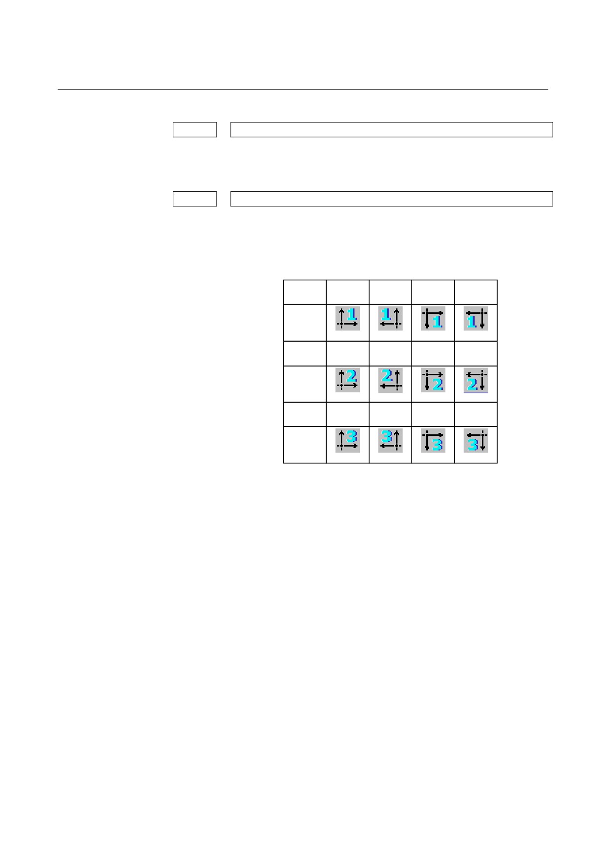
The values set to No.27188 and No.27189 must be selected from the
following table.
Icon
Number
11
12
13
14
icon
Icon
Number
21
22
23
24
icon
Icon
Number
31
32
33
34
icon
If the icon number which does not exist the above table is set to the
parameter, the icon for selected coordinate system is not displayed.
- 803 -
A.PARAMETERS
APPENDIX
B-63874EN/05
A.4.6
Parameters for Machining Simulation (Animated)
These parameters are for the settings for machining simulation
(animated).
27300
SCALE OF THE BLANK
(Byte type, FANUC standard settings = 0)
Scale magnification for automatic scaling in the machining simulation
function
Unit of data :
10 %
Valid data range :
0 to
20
(When
0 is set,
100% is
assumed.)
NOTE
1 In case of one Cs axis of main spindle, please be
sure to set No.14717 only. If no Cs axis or
Animation option, it is unnecessary to set.
2 In case of two Cs axis with main and sub spindle,
please be sure to set No.27301, No.27302 and
No.27312 #0. And No.14717 is used as working
number for Cs axis, as follows.
3 When 27312#0 = 1, No. 14717 is rewritten to the
value of No.27301 or No.27302 by a spindle
selection command (G1998). Therefore, in the
case of No.27312 #0=1, please be sure to specify
Spindle selection command (G1998) before Milling
cycles.
4 As to Apindle selection command (G1998), please
refer to “9.5 Setting of data for Animation”.
27301
ROTATE AXIS NO. (SP1)
(Byte type, FANUC standard settings = 0)
Rotation axis (Cs axis) number of Main spindle
<Related parameters : No.14717, No.27312#0, #1, #2, No.27302>
NOTE
Please be sure to specify Spindle selection
command (G1998 S1) before each Milling cycles.
27302
ROTATE AXIS NO. (SP2)
(Byte type, FANUC standard settings = 0)
Rotation axis (Cs axis) number of Sub spindle
<Related parameters : No.14717, No.27312#0, #1, #2, No.27301>
NOTE
Please be sure to specify Spindle selection
command (G1998 S2) before each Milling cycles.
- 804 -
B-63874EN/05
APPENDIX
A.PARAMETERS
27303
MTYPE
(Byte type, FANUC standard settings = 0)
MTYPE :
Type of machine mechanism
Type
Controlled rotary axis
Parameter setting for the axis
Without a rotary axis
Parameter No.14178 is a tool rotary
0
Or
axis.
With a tool rotary axis
With a workpiece table rotary
Parameter No.14178 is a workpiece
1
axis
table rotary axis.
<Related parameters : No.27301#1, No.27305, No.27307>
NOTE
1 No. of workpiece rotated axis (usually C-axis) is
set to the parameter No.14717. In the case of
machine mechanism type=1, this parameter must
not be set to workpiece table rotary axis No.
2 Drawing of machining simulation is not available
for a machine which takes a tool rotary axis with a
workpiece table rotary axis.
3 Drawing of machining simulation is not available
for a machine which has the roatry axis slant for
the basic three axis.
4 Machine mechanism type=2(With a workpiece
table rotary axis) is not available with multi-path
system or with a subspindle.
5 The axis to set to the parameter No.14718 is only
a rotary axis about Y axis.
27305
TBLDISTX
(2-word type, FANUC standard settings = 0)
TBLDISTX :
In the case that type of machine mechanism is type
1(With a
workpiece table rotary axis), distance (X-axis) from the rotary center
point to the rotary standard point of drawing blank figure. The
direction of + X axis is “+” for this data.
<Related parameters : No.27301#1, No.27303, No.27307>
- 805 -
A.PARAMETERS
APPENDIX
B-63874EN/05
27307
TBLDISTZ
(2-word type, FANUC standard settings = 0)
TBLDISTZ : In the case that type of machine mechanism is type
1(With a
workpiece table rotary axis), distance (Z-axis) from the rotary center
point to the rotary standard point of drawing blank figure. The
direction of - Z-axis is “+” for this data.
<Related parameters : No.27301#1, No.27303, No.27307>
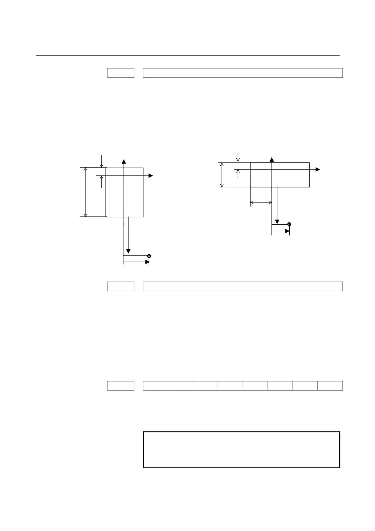
Rectangular solid blank form
Column blank form
Z
Z
WORK ORIGIN Z
REMOVAL K
X
Height of blank
X
Length of blank
WORK ORIGIN X
Parameter No.27307
Center point of rotary
table
Parameter No.27307
Parameter No.27305
Center point of rotary
table
Parameter No.27305
27309
DATA
(2-word type, FANUC standard settings = 0)
DATA : R signal for selected path simulation in Multi path lathe function
(The first figure is “bit” and other figure is the R signal number.)
In the multi-path lathe, the machining simulation is performed only
at the selected path by R signal that is set at this parameter.
For example, with 2 paths system
- At Path 1, the parameter No.27309=1237 (R123.7 is 1)
- At Path 2, the parameter No.27309=11237 (R1123.7 is 1)
#7
#6
#5
#4
#3
#2
#1
#0
27310
TLD
WOK
PRC
(FANUC standard settings = 00000000)
PRC
0 : The soft-key of [STOP] is displayed on the animation soft-key row.
1 : The soft-key of [PROC] is displayed instead of the soft-key [STOP].
NOTE
[STOP] is for the operation to stop with the end
block.
[PROC] is for the operation to stop with ‘M01’.
- 806 -
B-63874EN/05
APPENDIX
A.PARAMETERS
WOK
0 :
A blank figure is displayed on the tool path drawing screen or the
machining drawing screen when the drawing screen is opened.
1 :
A blank figure is displayed on the tool path drawing screen or the
machining drawing screen when a G code for blank figure definition
is executed.
TLD
0 :
The tag of [TOOL] is not displayed on START menu window.
1 :
The tag of [TOOL] is displayed on START menu window
#7
#6
#5
#4
#3
#2
#1
#0
27311
ACD
ITF
(FANUC standard settings = 00000000)
ITF
0 :
Animated simulation continues even when the interference check
function issues an interference alarm.
1 :
Animated simulation is stopped temporarily even when the
interference check function issues an interference alarm.
NOTE
Parameters No. 27310 and No. 27311 can not be
used in some editions.
ACD 0 :
Even If the workpiece coordinate is changed in performing
machining simulation, the drawing is performed on the same
workpiece coordinate as one on the top of simulation.( The workpiece
coordinate by drawing definition of blank form block is same as the
continuous-state workpiece coordinate on the top of simulation.)
1 :
If the workpiece coordinate is changed in performing machining
simulation, the drawing is performed on it.
NOTE
1 This parameter is availabel only in drawing of
machining sumulation. Drawing during machining
is always performed on the same workpiece
coordinate as the top of machining.
2 In multi-paths system, this parameter is a common
parameter at all paths.
3 In the case of ACD = 1, spindle at which animated
simulation is performed is the last commanded by
G1998 command at one of paths. In the case of
ACD = 0, spindle at which animated simulation is
performed is the last commanded by G1992 or
G1998 command at one of paths.
- 807 -
A.PARAMETERS
APPENDIX
B-63874EN/05
#7
#6
#5
#4
#3
#2
#1
#0
27312
INS
INA
SPA
(FANUC standard settings = 00000000)
SPA
0 :
The rotation axis number for simulation based on spindle 1 or spindle
2 with a subspindle attached is not switched by a spindle selection
command.
1 :
The rotation axis number for simulation based on spindle 1 or spindle
2 with a subspindle attached is switched by a spindle selection
command.
<Related parameters
: No.14717, No.27312#1,
#2, No.27301,
No.27302>
NOTE
When SPA = 1, No. 14717 is rewritten to the value
of No.27301 (in the case of G1998 S1) or
No.27302 (in the case of G1998 S2) by a spindle
selection command (G1998). So, please be sure to
specify a spindle selection command when SPA =
1.
INA
0 :
INS (#2) is not available.
1 :
INS (#2) is available.
NOTE
It is necessary to set SPA (#0) to 1.
INS
0 :
After animated simulation, No.14717 (the rotation axis number for
simulation) is rewritten to the value of No.27301 (axis number of
Main spindle).
1 :
After animated simulation, No.14717 (the rotation axis number for
simulation) is rewritten to the value of No.27302 (axis number of Sub
spindle).
NOTE
It is necessary to set SPA (#0) and INA (#1) to 1.
27323
MINMOV
(2-word type, FANUC standard settings=0)
MINMOV :
Least command increment for the tool in machining simulation
Unit of data : 1 [dot]
#7
#6
#5
#4
#3
#2
#1
#0
27350
GTP
(FANUC standard settings = 00000000)
GTP
0 :
When animate general tool, Tip position is in front
1 :
When animate general tool, Tip position is in rear
- 808 -

B-63874EN/05
APPENDIX
A.PARAMETERS
27351
GENR TIP LENGTH
(2-word type, FANUC standard settings=0)
GENR TIP LENGTH :
Cutter length when animate general tool
Input unit :
mm input (0000#2=0) : 0.001(mm)
inch input (0000#2=1) : 0.0001(inch)
Remarks)
If 0 is set in case of metric input (0000#2=0), default data will be
12mm.
If 0 is set in case of inch input(0000#2=1), default data will be
0.4724inch.
27352
GENR HOLD LENGTH
(2-word type, FANUC standard settings=0)
GENR HOLD LENGTH :
Holder length when animate general tool
Input unit :
mm input (0000#2=0) : 0.001(mm)
inch input (0000#2=1) : 0.0001(inch)
Remarks)
If 0 is set in case of metric input (0000#2=0), default data will be
50mm.
If 0 is set in case of inch input(0000#2=1), default data will be
1.9685inch.
27353
GENR HOLD WIDTH
(2-word type, FANUC standard settings=0)
GENR HOLD WIDTH :
Holder width when animate general tool
Input unit :
mm input (0000#2=0) : 0.001(mm)
inch input (0000#2=1) : 0.0001(inch)
Remarks)
If 0 is set in case of metric input (0000#2=0), default data will be
14mm.
If 0 is set in case of inch input(0000#2=1), default data will be
0.5512inch.
27354
GENR HOLD LENGTH2
(2-word type, FANUC standard settings=0)
GENR HOLD LENGTH2 :
Holder length2 when animate general tool
Input unit :
mm input (0000#2=0) : 0.001(mm)
inch input (0000#2=1) : 0.0001(inch)
27355
GENR HOLD WIDTH2
(2-word type, FANUC standard settings=0)
GENR HOLD WIDTH2 :
Holder width2 when animate general tool
Input unit :
mm input (0000#2=0) : 0.001(mm)
inch input (0000#2=1) : 0.0001(inch)
- 809 -

A.PARAMETERS
APPENDIX
B-63874EN/05
#7
#6
#5
#4
#3
#2
#1
#0
27356
TTP
(FANUC standard settings = 00000000)
TTP
0 : When animate threading tool, tip position is in front
1 : When animate threading tool, tip position is in rear
27357
THREAD TIP WIDTH
(2-word type, FANUC standard settings=0)
THREAD TIP WIDTH :
Tip width when animate threading tool
Input unit :
mm input (0000#2=0) : 0.001(mm)
inch input (0000#2=1) : 0.0001(inch)
Remarks)
If 0 is set in case of metric input (0000#2=0), default data will be
3mm.
If 0 is set in case of inch input(0000#2=1), default data will be
0.1181inch.
27358
THREAD HOLD LENGTH
(2-word type, FANUC standard settings=0)
THREAD HOLD LENGTH :
Holder length when animate threading tool
Input unit :
mm input (0000#2=0) : 0.001(mm)
inch input (0000#2=1) : 0.0001(inch)
Remarks)
If 0 is set in case of metric input (0000#2=0), default data will be
50mm.
If 0 is set in case of inch input(0000#2=1), default data will be
1.9685inch.
27359
THREAD HOLD WIDTH
(2-word type, FANUC standard settings=0)
THREAD HOLD WIDTH :
Holder width when animate threading tool
Input unit :
mm input (0000#2=0) : 0.001(mm)
inch input (0000#2=1) : 0.0001(inch)
Remarks)
If 0 is set in case of metric input (0000#2=0), default data will be
14mm.
If 0 is set in case of inch input(0000#2=1), default data will be
0.5512inch.
- 810 -
B-63874EN/05
APPENDIX
A.PARAMETERS
#7
#6
#5
#4
#3
#2
#1
#0
27360
GVP
(FANUC standard settings = 00000000)
GVP
0 : When animate grooving tool tip position is in front
1 : When animate grooving tool tip position is in rear
27361
GROOVE HOLD LENGTH
(2-word type, FANUC standard settings=0)
GROOVE HOLD LENGTH :
Holder length when animate grooving tool
Input unit :
mm input (0000#2=0) : 0.001(mm)
inch input (0000#2=1) : 0.0001(inch)
Remarks)
If 0 is set in case of metric input (0000#2=0), default data will be
50mm.
If 0 is set in case of inch input(0000#2=1), default data will be
1.9685inch.
27362
GROOVE HOLD WIDTH
(2-word type, FANUC standard settings=0)
GROOVE HOLD WIDTH :
Holder width when animate grooving tool
Input unit :
mm input (0000#2=0) : 0.001(mm)
inch input (0000#2=1) : 0.0001(inch)
Remarks)
If 0 is set in case of metric input (0000#2=0), default data will be
14mm.
If 0 is set in case of inch input(0000#2=1), default data will be
0.5512inch.
#7
#6
#5
#4
#3
#2
#1
#0
27363
BTP
(FANUC standard settings = 00000000)
BTP
0 : When animate button turning tool tip position is in front
1 : When animate button turning tool tip position is in rear
27364
BUTTON HOLD LENGTH
(2-word type, FANUC standard settings=0)
BUTTON HOLD LENGTH : Holder width when animate button turning tool
Input unit :
mm input (0000#2=0) : 0.001(mm)
inch input (0000#2=1) : 0.0001(inch)
Remarks)
If 0 is set in case of metric input (0000#2=0), default data will be
50mm.
If 0 is set in case of inch input(0000#2=1), default data will be
1.9685inch.
- 811 -
A.PARAMETERS
APPENDIX
B-63874EN/05
27365
BUTTON HOLD WIDTH
(2-word type, FANUC standard settings=0)
BUTTON HOLD WIDTH : Holder width when animate button turning tool
Input unit :
mm input (0000#2=0) : 0.001(mm)
inch input (0000#2=1) : 0.0001(inch)
Remarks)
If 0 is set in case of metric input (0000#2=0), default data will be
14mm.
If 0 is set in case of inch input(0000#2=1), default data will be
0.5512inch.
#7
#6
#5
#4
#3
#2
#1
#0
27366
STP
(FANUC standard settings = 00000000)
STP
0 : When animate straight tool, tip position is in front
1 : When animate straight tool, tip position is in rear
27367
STRAI TIP LENGTH
(2-word type, FANUC standard settings=0)
STRAI TIP LENGTH :
Tip length when animate straight tool
Input unit :
mm input (0000#2=0) : 0.001(mm)
inch input (0000#2=1) : 0.0001(inch)
Remarks)
If 0 is set in case of metric input (0000#2=0), default data will be
12mm.
If 0 is set in case of inch input(0000#2=1), default data will be
0.4724inch.
27368
STRAI HOLD LENGTH
(2-word type, FANUC standard settings=0)
STRAI HOLD LENGTH :
Holder length when animate straight tool
Input unit :
mm input (0000#2=0) : 0.001(mm)
inch input (0000#2=1) : 0.0001(inch)
Remarks)
If 0 is set in case of metric input (0000#2=0), default data will be
50mm.
If 0 is set in case of inch input(0000#2=1), default data will be
1.9865inch.
- 812 -

B-63874EN/05
APPENDIX
A.PARAMETERS
27369
STRAI HOLD WIDTH
(2-word type, FANUC standard settings=0)
STRAI HOLD WIDTH :
Holder width when animate straight tool
Input unit :
mm input (0000#2=0) : 0.001(mm)
inch input (0000#2=1) : 0.0001(inch)
Remarks)
If 0 is set in case of metric input (0000#2=0), default data will be
14mm.
If 0 is set in case of inch input(0000#2=1), default data will be
0.5512inch.
27370
STRAI HOLD LENGTH2
(2-word type, FANUC standard settings=0)
STRAI HOLD LENGTH2 :
Holder length 2 when animate straight tool
Input unit :
mm input (0000#2=0) : 0.001(mm)
inch input (0000#2=1) : 0.0001(inch)
27371
STRAI HOLD WIDTH2
(2-word type, FANUC standard settings=0)
STRAI HOLD WIDTH2 :
Holder width 2 when animate straight tool
Input unit :
mm input (0000#2=0) : 0.001(mm)
inch input (0000#2=1) : 0.0001(inch)
27372
DRILL TIP LENGTH
(2-word type, FANUC standard settings=0)
DRILL TIP LENGTH :
Holder width when animate straight tool
Input unit :
mm input (0000#2=0) : 0.001(mm)
inch input (0000#2=1) : 0.0001(inch)
Remarks)
If 0 is set in case of metric input (0000#2=0), default data will be
50mm.
If 0 is set in case of inch input(0000#2=1), default data will be
1.9865inch.
27373
F E MIL TIP LENGTH
(2-word type, FANUC standard settings=0)
F E MIL TIP LENGTH :
Tip length when animate flat end mill tool
Input unit :
mm input (0000#2=0) : 0.001(mm)
inch input (0000#2=1) : 0.0001(inch)
Remarks)
If 0 is set in case of metric input (0000#2=0), default data will be
50mm.
If 0 is set in case of inch input(0000#2=1), default data will be
1.9865inch.
- 813 -

A.PARAMETERS
APPENDIX
B-63874EN/05
27374
TAP TIP LENGTH
(2-word type, FANUC standard settings=0)
TAP TIP LENGTH :
Tip length when animate tapping tool
Input unit :
mm input (0000#2=0) : 0.001(mm)
inch input (0000#2=1) : 0.0001(inch)
Remarks)
If 0 is set in case of metric input (0000#2=0), default data will be
50mm.
If 0 is set in case of inch input(0000#2=1), default data will be
1.9865inch.
27376
C SINK TIP LENGTH
(2-word type, FANUC standard settings=0)
C SINK TIP LENGTH :
Tip length when animate counter sink tool
Input unit :
mm input (0000#2=0) : 0.001(mm)
inch input (0000#2=1) : 0.0001(inch)
Remarks)
If 0 is set in case of metric input (0000#2=0), default data will be
26mm.
If 0 is set in case of inch input(0000#2=1), default data will be
1.0236inch.
27377
C SINK CUT LENGTH
(2-word type, FANUC standard settings=0)
C SINK CUT LENGTH :
Cutter length when animate counter sink tool
Input unit :
mm input (0000#2=0) : 0.001(mm)
inch input (0000#2=1) : 0.0001(inch)
Remarks)
If 0 is set in case of metric input (0000#2=0), default data will be
50mm.
If 0 is set in case of inch input(0000#2=1), default data will be
1.9685inch.
27378
C SINK SHANK LENGTH
(2-word type, FANUC standard settings=0)
C SINK SHANK LENGTH :
Shank length when animate counter sink tool
Input unit :
mm input (0000#2=0) : 0.001(mm)
inch input (0000#2=1) : 0.0001(inch)
Remarks)
If 0 is set in case of metric input (0000#2=0), default data will be
130mm.
If 0 is set in case of inch input(0000#2=1), default data will be
5.1181inch.
- 814 -

B-63874EN/05
APPENDIX
A.PARAMETERS
27379
C SINK SHANK DIA
(2-word type, FANUC standard settings=0)
C SINK SHANK DIA :
Shank diameter when animate counter sink tool
Input unit :
mm input (0000#2=0) : 0.001(mm)
inch input (0000#2=1) : 0.0001(inch)
Remarks)
If 0 is set in case of metric input (0000#2=0), default data will be
32mm.
If 0 is set in case of inch input(0000#2=1), default data will be
1.2598inch.
27380
B E MIL TIP LENGTH
(2-word type, FANUC standard settings=0)
B E MIL TIP LENGTH :
Shank diameter when animate counter sink tool
Input unit :
mm input (0000#2=0) : 0.001(mm)
inch input (0000#2=1) : 0.0001(inch)
Remarks)
If 0 is set in case of metric input (0000#2=0), default data will be
50mm.
If 0 is set in case of inch input(0000#2=1), default data will be
1.9685inch.
27381
REAM TIP LENGTH
(2-word type, FANUC standard settings=0)
REAM TIP LENGTH :
Tip length when animate reamer tool
Input unit :
mm input (0000#2=0) : 0.001(mm)
inch input (0000#2=1) : 0.0001(inch)
Remarks)
If 0 is set in case of metric input (0000#2=0), default data will be
50mm.
If 0 is set in case of inch input(0000#2=1), default data will be
1.9685inch.
27382
BORING TIP LENGTH
(2-word type, FANUC standard settings=0)
BORING TIP LENGTH :
Tip length when animate boring tool
Input unit :
mm input (0000#2=0) : 0.001(mm)
inch input (0000#2=1) : 0.0001(inch)
Remarks)
If 0 is set in case of metric input (0000#2=0), default data will be
50mm.
If 0 is set in case of inch input(0000#2=1), default data will be
1.9685inch.
- 815 -

A.PARAMETERS
APPENDIX
B-63874EN/05
27383
F MIL TIP LENGTH
(2-word type, FANUC standard settings=0)
F MIL TIP LENGTH : Tip length when animate face mill tool
Input unit :
mm input (0000#2=0) : 0.001(mm)
inch input (0000#2=1) : 0.0001(inch)
Remarks)
If 0 is set in case of metric input (0000#2=0), default data will be
63mm.
If 0 is set in case of inch input(0000#2=1), default data will be
2.4803inch.
A.4.7
Parameter for Machining Simulation (Animated)
27390
M-CODE AVERAGE TIME
(2-word type, FANUC standard settings=0)
M-CODE AVERAGE TIME
:
Execution time of averaged M code
This parameter is used for calculating machining time.
data unit : 10(msec)
valid data range : 0-99999999
27391
S-CODE AVERAGE TIME
(2-word type, FANUC standard settings=0)
S-CODE AVERAGE TIME
:
Execution time of averaged S code
This parameter is used for calculating machining time.
data unit : 10(msec)
valid data range : 0-99999999
27390
T-CODE AVERAGE TIME
(2-word type, FANUC standard settings=0)
T-CODE AVERAGE TIME
:
Execution time of averaged T code
This parameter is used for calculating machining time.
data unit : 10(msec)
valid data range : 0-99999999
- 816 -
B-63874EN/05
APPENDIX
A.PARAMETERS
A.4.8
Parameters for Multi-path Lathe Function
These parameters are for the Multi-path lathe function.
#7
#6
#5
#4
#3
#2
#1
#0
27400
SPT
(FANUC standard settings = 00000000)
SPT
0 : Tool post is selection by the software key
1 : Tool post is selection by the HEAD switch signal
(common parameter among paths)
#7
#6
#5
#4
#3
#2
#1
#0
27401
MR2
SR2
SSP
SMP
SSE
SME
(FANUC standard settings = 00000000)
SME
0 :
Tool post 2 cannot be used with spindle 1.
1 :
Tool post 2 can be used with spindle 1.
SSE
0 :
Tool post 2 cannot be used with spindle 2.
1 :
Tool post 2 can be used with spindle 2.
NOTE
SSE is available in the case of Parameter
No.14702 SUB(#1) = 1 only.
SMP
0 :
Tool post 2 is placed above spindle 1.
1 :
Tool post 2 is placed under spindle 1.
NOTE
SMP is available in the case of Parameter
No.27401 SME(#0) = 1 only.
SSP
0 :
Tool post 2 is placed above spindle 2.
1 :
Tool post 2 is placed under spindle 2.
(common parameter among paths)
NOTE
SSP is available in the case of Parameters
No.14702 SUB(#1) = 1 and No.27401 SSE(#1) = 1
only.
- 817 -
A.PARAMETERS
APPENDIX
B-63874EN/05
#7
#6
#5
#4
#3
#2
#1
#0
27402
TSP
TMP
TSE
TME
(FANUC standard settings = 00000000)
TME
0 :
Tool post 3 cannot be used with spindle 1.
1 :
Tool post 3 can be used with spindle 1.
TSE
0 :
Tool post 3 cannot be used with spindle 2.
1 :
Tool post 3 can be used with spindle 2.
NOTE
TSE is available in the case of Parameter
No.14702 SUB(#1) = 1 only.
TMP
0 :
Tool post 3 is placed above spindle 1.
1 :
Tool post 3 is placed under spindle 1.
NOTE
TMP is available in the case of Parameter
No.27402 TME(#0) = 1 only.
TSP
0 :
Tool post 3 is placed above spindle 2.
1 :
Tool post 3 is placed under spindle 2.
(common parameter among paths)
NOTE
TSP is available in the case of Parameters
No.14702 SUB(#1) = 1 and No.27402 TSE(#1) = 1
only.
- 818 -
B-63874EN/05
APPENDIX
A.PARAMETERS
A.4.9
Parameters for Icon of Path Number Display
These parameters are for Icon of path number display.
27410
P1ICON
(Byte type, FANUC standard settings=0)
P1ICON :
ICON number when path-1 is selected
(common parameter among paths)
27411
P2ICON
(Byte type, FANUC standard settings=0)
P2ICON :
ICON number when path-2 is selected
(common parameter among paths)
27412
P3ICON
(Byte type, FANUC standard settings=0)
P3ICON :
ICON number when path-3 is selected
(common parameter among paths)
= 0 : nothing
= 1 : path-1 with lower direction and opposite to another
(2 path system)
= 2 : path-1 with upper direction and opposite to another
(2 path system)
= 3 : path-2 with upper direction and opposite to another
(2 path system)
= 4 : path-2 with lower direction and opposite to another
(2 path system)
= 5 : path-2 with upper direction and parallel to another
(2 path system)
= 6 : path-2 with lower direction and parallel to another
(2 path system)
= 10 : single path-1 with lower direction (3 path system)
= 11 : right side path-1 with upper direction (3 path system)
= 12 : left side path-1 with upper direction (3 path system)
= 13 : single path-1 with upper direction (3 path system)
= 14 : right side path-1 with lower direction (3 path system)
= 15 : left side path-1 with lower direction (3 path system)
= 20 : right side path-2 with upper direction (3 path system)
= 21 : left side path-2 with upper direction (3 path system)
= 22 : single side path-2 with lower direction (3 path system)
= 23 : right side path-2 with lower direction (3 path system)
= 24 : left side path-2 with lower direction (3 path system)
= 25 : single path-2 with upper direction (3 path system)
= 30 : left side path-3 with upper direction (3 path system)
= 31 : right side path-3 with upper direction (3 path system)
= 32 : single side path-3 with lower direction (3 path system)
= 33 : left side path-3 with lower direction (3 path system)
= 34 : right side path-3 with lower direction (3 path system)
= 35 : single path-3 with upper direction (3 path system)
- 819 -
A.PARAMETERS
APPENDIX
B-63874EN/05
A.4.10 Other Parameters
This parameter is set for Macro executor and available only in Series
16i/18i/21i systems.
#7
#6
#5
#4
#3
#2
#1
#0
27500
FSV
(FANUC standard settings = 00000000)
FSV In the case of using “Controlling conversational macro function
screens” (#8510) in a Macro executor which is made by MTB, if
#8510 is set in displaying a window screen of MANUAL GUIDE i,
0 :
#8510 is stored and when the window display is closed, #8510 setting
is restored.
1 :
#8510 is disregarded.
- 820 -
B-63874EN/05
APPENDIX
B.ALARMS
B
ALARMS
If the input program or one or more parameter settings are not correct,
the following P/S alarms are raised.
When an alarm other than the following P/S alarms is raised, refer to
the relevant NC operator's manual.
NOTE
In Series 30i, the alarm is not P/S, but MC.
Alarm
Description
16i
30i
There is no area that can be machined. The tool is too large for the specified machining
Cause
3003
3503
area.
Action
Modify the machining program to use a smaller tool.
Cause
The number of cuts has exceeded the limit.
3004
3504
Modify the machining program to reduce the number of cuts by, for example, dividing the
Action
machining profile.
Cause
The machining start point is invalid.
3005
3505
Either change the machining start point to a normal one or modify the machining program
Action
to automatically decide the point.
Cause
The machining area is invalid.
3006
3506
Modify the machining program to specify a correct machining area, such as a part figure
Action
and a blank figure in a machining profile.
Cause
The cutting conditions are invalid.
3007
3507
Action
Modify the machining program to specify normal cutting conditions such as the feedrate.
Cause
Finishing is not possible under the specified conditions.
3008
3508
Action
Review the finishing program.
An interference occurred. For example, the tool path may interfere with the opposite
Cause
machining area.
3009
3509
For example, the cutter radius may be too large for the machining area. Modify the
Action
machining program.
No machining cycle is found. No machining type block is found; only a figure block is
Cause
specified.
3010
3510
Modify the machining program by, for example, adding the necessary machining type
Action
block.
Cause
No machining cycle is found. An unavailable machining cycle is specified.
3011
3511
Action
Necessary options may not be added. Contact the machine tool builder.
G codes that cannot be combined together. A figure block not available to the machining
Cause
type block is specified.
3012
3512
Modify the machining program to specify a correct combination of machining type block
Action
and figure block.
Cause
The arbitrary figure is invalid.
3013
3513
Action
Modify the machining program to specify a correct arbitrary figure.
Cause
The figure data is invalid.
3014
3514
Action
Modify the machining program to specify correct figure data.
- 821 -