FANUC MANUAL GUIDE i. OPERATOR’S MANUAL - page 27

A.PARAMETERS
APPENDIX
B-63874EN/05
14765
GIDCOL10
GIDCOL10 :
Portion to be cut.
14766
GIDCOL11
GIDCOL11 :
Finishing allowance.
14767
GIDCOL12
GIDCOL12 :
Reserved.
14768
GIDCOL13
GIDCOL13 :
Reserved.
14769
GIDCOL14
GIDCOL14 :
Explanation of measurement (static sentence)
14770
GIDCOL15
GIDCOL15 :
Explanation of measurement (dynamic sentence)
14771
GIDCOL16
GIDCOL16 :
Background color.
If these parameters are set to 0, the following values are used as their
respective initial values.
No.14756 = 003200
Green
No.14757 = 000063
Blue
No.14758 = 000063
Blue
No.14759 = 006060
Light blue
No.14760 = 006060
Light blue
No.14761 = 600000
Red
No.14762 = 000063
Blue
No.14763 = 000063
Blue
No.14764 = 636300
Yellow
No.14756 = 484848
Bright gray
No.14766 = 404040
Rather bright gray
No.14767 = 000000
Black (reserved)
No.14768 = 000000
Black (reserved)
No.14769 = 636363
White
No.14770 = 006060
Light blue
No.14771 = 242424
Dark gray
- 762 -

B-63874EN/05
APPENDIX
A.PARAMETERS
A.2.12
Settings for Tool Path Drawing Colors
These parameters set the tool path drawing colors.
•
Specify color setting data with a 6-digit number in the format of
“xxyyzz”.
(xx:Value for red, yy:Value for green, zz:Value for blue)
•
The valid data range of each color value is 0 to 63. A value
greater than 63 is interpreted as 63.
•
For a number with less than six digits, all the unspecified digits
are interpreted as high-order ones and are all assumed 0.
14773
DATA
DATA : Color of blank figure during tool path drawing.
If the value is set to 0, Green is used as the respective initial values
(003200).
A.2.13
Settings for Machining Simulation Animation Colors
These parameters set machining simulation animation colors.
•
Specify color setting data with a 6-digit number in the format of
“xxyyzz”.
(xx:Value for red, yy:Value for green, zz:Value for blue)
•
The valid data range of each color value is 0 to 63. A value
greater than 63 is interpreted as 63.
•
For a number with less than six digits, all the unspecified digits
are interpreted as high-order ones and are all assumed 0.
14777
ANMCOL1
ANMCOL1 :
Color of part figures during animation.
14778
ANMCOL2
ANMCOL2 :
Color of material cut-off portions during animation.
14779
ANMCOL3
ANMCOL3 :
Color of the tool during animation.
14780
ANMCOL4
ANMCOL4 :
Color of the coordinate axes during animation.
14781
ANMCOL5
ANMCOL5 :
Color of the background during animation.
If these parameters are set to 0, their standard colors are assumed.
- 763 -

A.PARAMETERS
APPENDIX
B-63874EN/05
A.2.14
Settings for Path Colors During Tool Path Plotting
These parameters set the path colors used during tool path plotting.
•
Specify color setting data with a 6-digit number in the format of
“xxyyzz”.
(xx:Value for red, yy:Value for green, zz:Value for blue)
•
The valid data range of each color value is 0 to 63. A value
greater than 63 is interpreted as 63.
•
For a number with less than six digits, all the unspecified digits
are interpreted as high-order ones and are all assumed 0.
14785
PATHCOL1
PATHCOL1 : Color of the path of a rapid traverse tool.
14786
PATHCOL2
PATHCOL2 : Color of the path of a cutting feed tool.
14787
PATHCOL3
PATHCOL3 : Color of the path of a threading tool.
If these parameters are set to 0, their standard colors are assumed.
- 764 -
B-63874EN/05
APPENDIX
A.PARAMETERS
A.2.15
Settings for the Allocation of Startup Function Keys
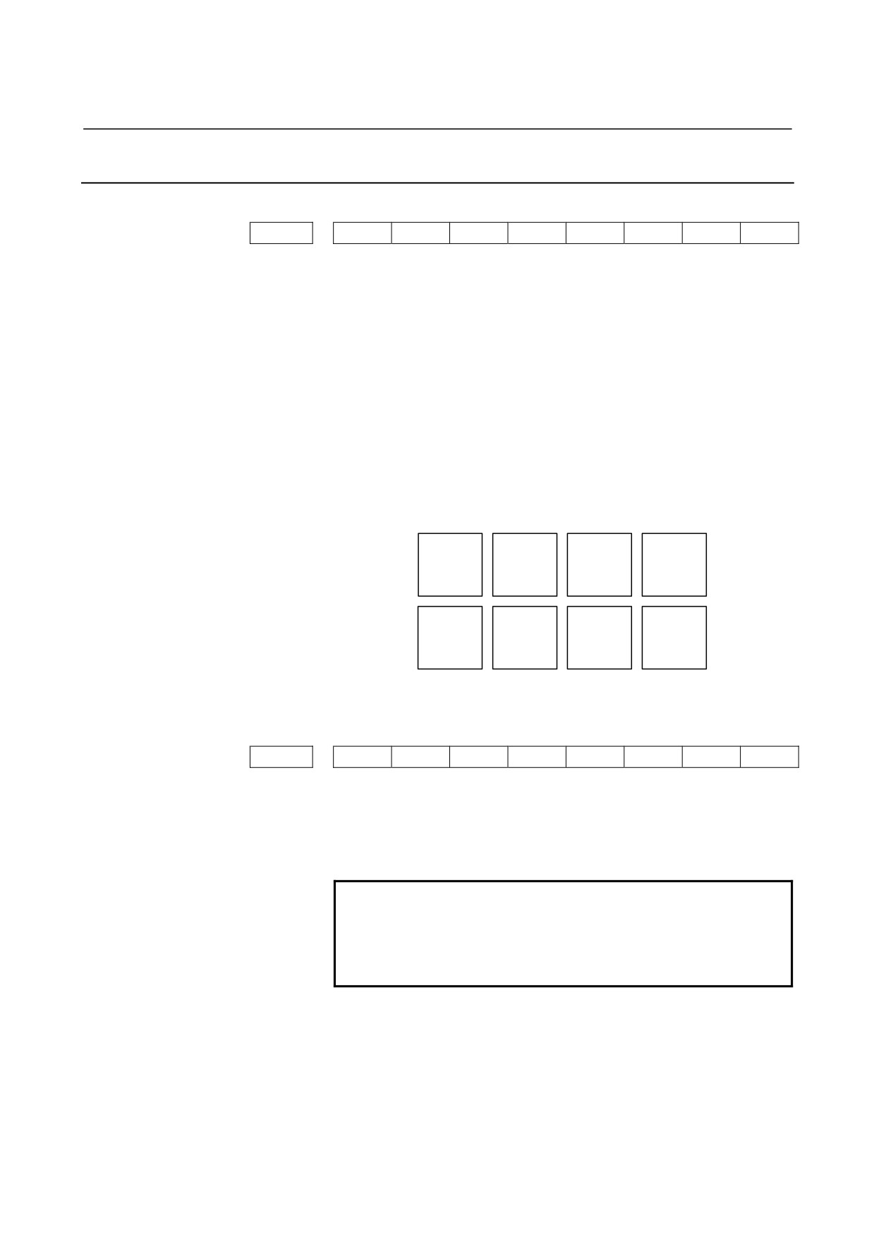
#7
#6
#5
#4
#3
#2
#1
#0
14794
GRP
MES
SYS
OFS
PRG
POS
POS
0 : The Manual Guide does not start when function key <1> is pressed.
1 : The Manual Guide starts when function key <1> is pressed.
PRG
0 : The Manual Guide does not start when function key <2> is pressed.
1 : The Manual Guide starts when function key <2> is pressed.
OFS
0 : The Manual Guide does not start when function key <3> is pressed.
1 : The Manual Guide starts when function key <3> is pressed.
SYS
0 : The Manual Guide does not start when function key <4> is pressed.
1 : The Manual Guide starts when function key <4> is pressed.
MES
0 : The Manual Guide does not start when function key <5> is pressed.
1 : The Manual Guide starts when function key <5> is pressed.
GRP
0 : The Manual Guide does not start when function key <6> is pressed.
1 : The Manual Guide starts when function key <6> is pressed.
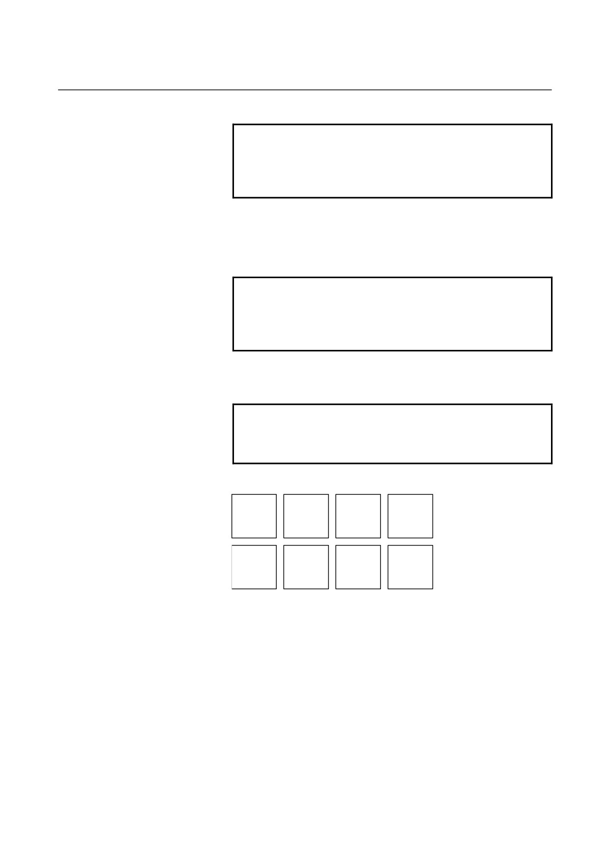
<1>
<2>
<3>
OFFSET
POS
PROG
SETTING
SYSTEM
MESAGE
GRAPH
<4>
<5>
<6>
#7
#6
#5
#4
#3
#2
#1
#0
14795
PS3
PS2
PS1
FPT
CS3
CS2
CS1
CS1
0 : The Manual Guide does not start on Custom Screen 1 (AUX) when
function key <1> is pressed.
1 : The Manual Guide starts on Custom Screen 1 (AUX) when function
key <1> is pressed.
NOTE
1 If the conversational macro screen is not provided,
bit 5 of parameter No. 8652 (CMEC1) must be set
to 1.
2 This parameter is not supported in Series 30i.
CS2
0 : The Manual Guide does not start on Custom Screen 3 (MCR) when
function key <1> is pressed.
1 : The Manual Guide starts on Custom Screen 3 (MCR) when function
key <1> is pressed.
- 765 -
A.PARAMETERS
APPENDIX
B-63874EN/05
NOTE
1 If the conversational macro screen is not provided,
bit 6 of parameter No. 8652 (CMEC2) must be set
to 1.
2 This parameter is not supported in Series 30i.
CS3
0 :
The Manual Guide does not start on Custom Screen 2 (MENU) when
function key <1> is pressed.
1 :
The Manual Guide starts on Custom Screen 2 (MENU) when function
key <1> is pressed.
NOTE
1 If the conversational macro screen is not provided,
bit 7 of parameter No. 8652 (CMEC3) must be set
to 1.
2 This parameter is not supported in Series 30i.
FPT
0 :
The Manual Guide does not start when function key <2> is pressed.
1 :
The Manual Guide starts when function key <2> is pressed.
NOTE
1 Bit 4 of parameter No. 8652 (CMECF) must be set
to 1.
2 This parameter is not supported in Series 30i.
<1>
CUSTOM
FAPT
<2>
PS3=0, PS2=0, PS1=0 : The maximum memory size is set to 250K byte.
PS3=0, PS2=0, PS1=1 : The maximum memory size is set to 500K byte.
PS3=0, PS2=1, PS1=0 : The maximum memory size is set to 1M byte.
PS3=0, PS2=1, PS1=1 : The maximum memory size is set to 2M byte.
PS3=1, PS2=0, PS1=0 : The maximum memory size is set to 4M byte.
PS3=1, PS2=0, PS1=1 : The maximum memory size is set to 5M byte.
PS3=1, PS2=1, PS1=0 : The maximum memory size is set to 6M byte.
PS3=1, PS2=1, PS1=1 : The maximum memory size is set to 7M byte.
- 766 -
B-63874EN/05
APPENDIX
A.PARAMETERS
NOTE
PS3, PS2 and PS1 are set in the 1 path parameter
only.
To specify a maximum allowable memory size
greater than 250K bytes in parameter No. 14795,
set an appropriate value in parameter No. 8781
(DRAM size that can be used by a C language
application).
To increase the DRAM size, the custom capacity
option is separately required.
* If the DRAM size is increased by 1M bytes by
using parameter No. 8781, about 500,000
characters (about 20,000 blocks) can be increased
as a guideline when one block consists of 25
characters on average.
- 767 -

A.PARAMETERS
APPENDIX
B-63874EN/05
A.2.16
Settings for Current Position Display
14799
DS1AXS
DS1AXS
0 :
The first controlled axis is displayed in display area 1.
≠0 :
Number of the controlled axis to be displayed in display area 1.
14800
DS2AXS
DS2AXS
0 :
The second controlled axis is displayed in display area 2.
≠0 :
Number of the controlled axis to be displayed in display area 2.
14801
DS3AXS
DS3AXS
0 :
The third controlled axis is displayed in display area 3.
≠0 :
Number of the controlled axis to be displayed in display area 3.
14802
DS4AXS
DS4AXS
0 :
The fourth controlled axis is displayed in display area 4.
≠0 :
Number of the controlled axis to be displayed in display area 4.
14803
DS5AXS
DS5AXS
0 :
The fifth controlled axis is displayed in display area 5.
≠0 :
Number of the controlled axis to be displayed in display area 5.
14804
DS6AXS
DS6AXS
0 :
The sixth controlled axis is displayed in display area 6.
≠0 :
Number of the controlled axis to be displayed in display area 6.
14805
DS7AXS
DS7AXS
0 :
The seventh controlled axis is displayed in display area 7.
≠0 :
Number of the controlled axis to be displayed in display area 7.
14806
DS8AXS
DS8AXS
0 :
The eighth controlled axis is displayed in display area 8.
≠0 :
Number of the controlled axis to be displayed in display area 8.
- 768 -

B-63874EN/05
APPENDIX
A.PARAMETERS
A.2.17
Settings for F Load Meter Compensation
Parameters Nos. 14815 to 14822 are independent ones for respective
paths.
These parameters are used to compensate a CNC controlled axis to
which load is applied constantly, such as a vertical axis, for that load,
using the load meter.
14815
ELOFS1
ELOFS1 :
Value of the load current of the first CNC controlled axis in the steady
status, as converted into a digital value (-6554 to +6554).
14816
ELOFS2
ELOFS2 :
Value of the load current of the second CNC controlled axis in the
steady status, as converted into a digital value (-6554 to +6554).
14817
ELOFS3
ELOFS3 :
Value of the load current of the third CNC controlled axis in the
steady status, as converted into a digital value (-6554 to +6554).
14818
ELOFS4
ELOFS4 :
Value of the load current of the fourth CNC controlled axis in the
steady status, as converted into a digital value (-6554 to +6554).
14819
ELOFS5
ELOFS5 :
Value of the load current of the fifth CNC controlled axis in the steady
status, as converted into a digital value (-6554 to +6554).
14820
ELOFS6
ELOFS6 :
Value of the load current of the sixth CNC controlled axis in the
steady status, as converted into a digital value (-6554 to +6554).
14821
ELOFS7
ELOFS7 :
Value of the load current of the seventh CNC controlled axis in the
steady status, as converted into a digital value (-6554 to +6554).
14822
ELOFS8
ELOFS8 :
Value of the load current of the eighth CNC controlled axis in the
steady status, as converted into a digital value (-6554 to +6554).
- 769 -

A.PARAMETERS
APPENDIX
B-63874EN/05
A.2.18
Settings for Tool Management Functions
These parameters are for the settings for tool management functions.
#7
#6
#5
#4
#3
#2
#1
#0
14823
STS
TLD
LIA
LIF
TMG
MSR
TOF
ORT
ORT
0 :
The screen for associating a tool number with a compensation number
is not displayed.
1 :
The screen for associating a tool number with a compensation number
is displayed.
TOF
0 :
The per-tool-number tool offset setting screen is not displayed.
1 :
The per-tool-number tool offset setting screen is displayed.
MSR
0 :
The compensation type, tool number, and group number input fields
are not displayed on the measurement screen.
1 :
The compensation type, tool number, and group number input fields
are displayed on the measurement screen.
TMG
0 :
The tool management data setting screen is not displayed.
1 :
The tool management data setting screen is displayed.
LIF
0 :
The tool life management data setting screen is not displayed.
1 :
The tool life management data setting screen is displayed.
LIA
0 :
The screen of Tool Life Data List is not displayed.
1 :
The screen of Tool Life Data List is displayed.
TLD
0 :
The soft-key for changing screen from Manual Guide i to Tool
Management Data Table is not displayed.
1 :
The soft-key for changing screen from Manual Guide i to Tool
Management Data Table is displayed.
STS
0 :
When a compensation type is specified, the compensation type is not
displayed in the status display area.
1 :
When a compensation type is specified, the compensation type is
displayed in the status display area.
14824
OFSRELTL
OFSRELTL :
Start compensation number (0 to 999) to be associated with a tool
number.
14825
OFSTYPNO
OFSTYPO :
Number of compensation types (0 to 9)
- 770 -
B-63874EN/05
APPENDIX
A.PARAMETERS
A.2.19
Settings for Arbitrary Figures
These parameters are for the settings for arbitrary shapes.
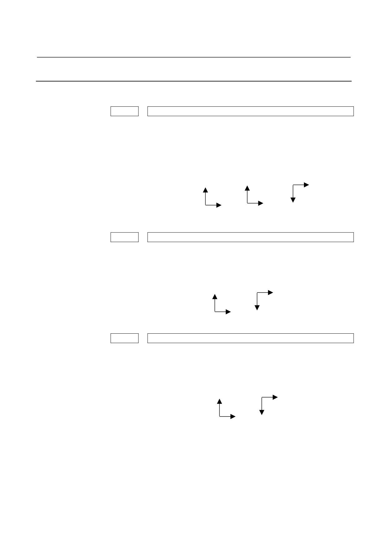
14840
DSPCRDZX
DSPCRDZX :
Drawing coordinates when an arbitrary ZX figure is programmed.
= 0
Same effect as that of setting 5.
= 1
Plan view, horizontal axis = +X, vertical axis = +Z
= 5
Plan view, horizontal axis = +Z, vertical axis = +X
= 6
Plan view, horizontal axis = +Z, vertical axis = -X
Z
X
Z
Z
X
X
6
5
1
14841
DSPCRDZC
DSPCRDZC :
Drawing coordinates when an arbitrary ZC figure is programmed.
= 0
Same effect as that of setting 6.
= 1
Plan view, horizontal axis = +C, vertical axis = +Z
= 6
Plan view, horizontal axis = +Z, vertical axis = -C
Z
Z
C
C
1
6
14842
DSPCRDYZ
DSPCRDYZ :
Drawing coordinates when an arbitrary YZ figure is programmed.
= 0
Same effect as that of setting 6.
= 1
Plan view, horizontal axis = + Y, vertical axis = +Z
= 6
Plan view, horizontal axis = +Z, vertical axis = -Y
Z
Z
Y
Y
1
6
- 771 -
A.PARAMETERS
APPENDIX
B-63874EN/05
A.2.20 Other Parameters
14843
Number of blocks which is used to judge if a subprogram calling
“M98 P****” is arbitrary figure data when a cursor is on the block of
the subprogram calling in the program-editing screen.
= A positive number Number of blocks
= 0 All of the subprogram
= -1 None of the subprogram (The arbitrary figures of the subprogram are
not drawn.)
14844
A cycle time when the date and the time are recorded in an operating
history.
The date and the time are recorded in an operating history every the
set time. However, the date and the time are not recorded if there is no
operating data in the time.
Valid data range : 0 to 1439
Unit of data : 1 [min]
- 772 -

B-63874EN/05
APPENDIX
A.PARAMETERS
A.2.21
Settings for Operations in General (All Common Path)
These parameters are for the settings for operations in general.
#7
#6
#5
#4
#3
#2
#1
#0
14850
#0
0 :
In the tool offset window, the tab of [TOOL DATA] is displayed.
1 :
In the tool offset window, the tab of [TOOL DATA] is not displayed.
NOTE
#0 is necessary to order the optional function of
Milling Cycles or Turning Cycles.
#1
0 :
In the workpiece coordinate system window and tool offset window,
[CHCURS] can not be changed.
1 :
In the workpiece coordinate system window and tool offset window,
[CHCURS] can be changed into [TAB→].
#2
0 :
The soft-key
[RETURN] is displayed on Tool Management Data
screen and Manual Measurement screen.
1 :
The soft-key [CLOSE] is displayed on Tool Management Data screen
and Manual Measurement screen.
#3
0 :
Fixed form sentence editing is not disabled with the Memory
Protection key
1 :
Fixed form sentence editing is disabled with the Memory Protection
key
#4
0 :
The soft-key [M CODE] is displayed on the basic screen.
1 :
The soft-key [M CODE] is not displayed on the basic screen
#5
0 :
When a program is opened, a check for an invalid character is not
made.
1 :
When a program is opened, a check for an invalid character is made.
(When bit 5 is set to 1, a longer time is required to open a program.)
#6
0 :
When MANUAL GUIDE i is used with the function key [PROG],
switching from the MGi screen to the NC screen to the MGi screen is
performed in mode switching.
1 :
When MANUAL GUIDE i is used with the function key [PROG],
switching from the MGi screen to the NC screen to the MGi screen is
not performed in mode switching.
#7
0 :
If no modification is made to the program size and time stamp (in
minutes) at the time of screen switching from the NC screen to the
MGi screen, the program is not read again.
1 :
The program is always read again at the time of screen switching from
the NC screen to the MGi screen.
- 773 -
A.PARAMETERS
APPENDIX
B-63874EN/05
#7
#6
#5
#4
#3
#2
#1
#0
14851
GCC
PKW
W12
SBP
#0
0 :
Corner element between a blank element and a part element is created
in the normal direction at creating free figure.
1 :
Corner element between a blank element and a part element is created
in the opposite direction at creating free figure.
SBP
0 :
When the [INSERT] soft key is pressed on the fixed form figure input
screen, the subprogram output selection screen is not displayed.
1 :
When the [INSERT] soft key is pressed on the fixed form figure input
screen, the subprogram output selection screen is displayed.
W12
0 :
In the case of editing on the process list screen, the address W1 and
W2 are not output with the Process Start Block(G1992).
1 :
In the case of editing on the process list screen, the address W1 and
W2 are output with the Process Start Block(G1992).
PWK
0 :
The “PROGRAM COORDINATE” input item does not appear on the
entry window for the arbitrary figures.
1 :
The “PROGRAM COORDINATE” input item appears on the entry
window for the arbitrary figures.
GCC
0 :
On tool offset screen and workpiece shift offset screen, the display
data for each program coordinate system changes by soft-key.
1 :
On tool offset screen and workpiece shift offset screen, the display
data for each program coordinate system changes by
DO-signal(F0347#GCO).
#7
0 :
Not inhibit to edit the tool management data at NC screen.
1 :
Inhibit to edit the tool management data at NC screen
#7
#6
#5
#4
#3
#2
#1
#0
14852
CFF
G4E
NTC
NTC In the drawing during machining,
0 : Conpensates the tool offset.
1 : Not conpensates the tool offset.
G4E
0 : When a cursor is placed on the word in the cycle machining block and
an operator is going to insert a new word, the warning will be
displayed.
1 : When a cursor is placed on the word in the cycle machining block and
an operator is going to insert a new word, the warning will not be
displayed.
CFF
0 : The number of fixed form sentences per tab is 10 and the characters
per fixed form sentence is 128.
1 : The number of fixed form sentences per tab decreases to 5 and the
characters per fixed form sentence increase to 256.
#6
0 : The tool data access function is not used.
1 : The tool data access function is used.
#7
0 : Each time an operation is performed, check is made to see if BG
editing is in progress.
1 : Each time an operation is performed, no check is made to see if BG
editing is in progress.
- 774 -
B-63874EN/05
APPENDIX
A.PARAMETERS
A.2.22
Settings for Operations in General (For Series 30i)
These parameters are for the settings for operations in general in
Series 30i.
#7
#6
#5
#4
#3
#2
#1
#0
14853
#0
0 : The program list screen based on the new specifications is used.
1 : The program list screen based on the old specifications is used.
#1
0 : When the function key [PROG] is pressed, the screen display toggles
between the NC program screen and the program list screen.
1 : When the function key [PROG] is pressed, the NC program screen is
displayed at all times.
#2
0 : When the [O SRCH] key is pushed with empty of key-in-buffer , the
program number is searched
1 : When the [O SRCH] key is pushed with empty of key-in-buffer , the
program number is not searched.
#7
0 : The program window screen in machining based on the old
specifications is used. (Scroll bar is not displayed)
1 : The program window screen in machining based on the new
specifications is used. (Scroll bar is displayed)
A.2.23 Settings for Operations in General (For Multi C Executor)
These parameters are for the settings for operations in general in multi
C executor.
#7
#6
#5
#4
#3
#2
#1
#0
14854
#7
0 : When multiple applications are used, MANUAL GUIDE i exercise
screen display control immediately after the power is turned on.
1 : When multiple applications are used, MANUAL GUIDE i does not
exercise screen display control immediately after the power is turned
on.
(An application of the machine tool builder exercises screen
display control.)
- 775 -
A.PARAMETERS
APPENDIX
B-63874EN/05
A.2.24 Settings for Operations in General (Each Path)
These parameters are for the settings for operations in general.
#7
#6
#5
#4
#3
#2
#1
#0
14855
#0
0 : In the tool offset window, Y-axis offset data is displayed.
1 : In the tool offset window, Y-axis offset is not displayed.
PRC
0 : When the Program Coordinate System Changing Function is enabled,
the coordinate system on the first spindle side is the program
coordinate system-1 and the coordinate system on the second spindle
side is the program coordinate system-2.
1 : When the Program Coordinate System Changing Function is enabled,
the coordinate system on the first spindle side is the program
coordinate system-2 and the coordinate system on the second spindle
side is the program coordinate system-1.
NOTE
This parameter #0 is necessary to order the
optional function of Y-axis offset data display
A.2.25
Settings for Operations in General (All Common Path)
These parameters are for the settings for operations in general.
14860
DATA
DATA : Special character for search function in the program display window
on the base screen.
Please set the decimal number of ASCII.
If the value is 0, the special character is assumed to be “?”.
Special characters are used with the following functions:
<1> In program display, the color of special characters is changed for
display.
<2> If a fixed form sentence to be inserted includes special characters,
a warning message is indicated.
14861
UNDOBUF
UNDOBUF : Specify the total size of the buffer for use with the redo and undo
functions.
If 0 is input, 5 KB of buffer space is allocated. If a negative value is
input, the redo and undo functions cannot be used.
Valid data range : -127 to 127
Unit of data : 1 [KB]
- 776 -
B-63874EN/05
APPENDIX
A.PARAMETERS
A.2.26 Settings for Arbitrary Figures(XA Plane)
These parameters are for the settings for arbitrary figures.
14862
DSPCRDXA
DSPCRDXA : Drawing coordinates when an arbitrary ZC figure is programmed.
=0 Same effect as that of setting 6.
=1 Plan view, horizontal axis = +A, vertical axis = +X
=6 Plan view, horizontal axis = +X, vertical axis = -A
X
X
A
A
1
6
- 777 -
A.PARAMETERS
APPENDIX
B-63874EN/05
A.3
PARAMETERS FOR MILLING CYCLE MACHINING
A.3.1
Parameters for Milling Cycles in General
These parameters are for the settings for milling cycles in general.
#7
#6
#5
#4
#3
#2
#1
#0
27000
MC7
MC6
MC5
MC4
MC3
MC2
MC1
MC0
MC0
0 :
In ZC plane cycle output, G02/G03 are inverted.
1 :
In ZC plane cycle output, G02/G03 are not inverted.
MC1
0 :
The hole machining menu has hole machining items for M.
Remark) Refer to “1.1 Hole Machining by Milling”.
1 :
The hole machining menu has hole machining items for T.
Remark) Refer to “1.2 Hole Machining by Turning”.
MC2
0 :
In XC plane cycle output, G12.1/G13.1 are not output.
1 :
In XC plane cycle output, G12.1/G13.1 are output.
Remark) Refer to the paragraph of XC plane figure of Facing,
Contouring, Pocketing or Grooving.
MC3
0 :
In ZC plane cycle output, G07.1 is not output.
1 :
In ZC plane cycle output, G07.1 is output.
Remark) Refer to the paragraph of ZC plane figure of Facing,
Contouring, Pocketing or Grooving.
MC4
0 :
In cycle input screens, the tab of [FACE POSIT] for end face position
is not displayed.
1 :
In cycle input screens, the tab of [FACE POSIT] for end face position
is displayed.
Remark) Refer to “1.8 Rear End Facing by Milling”.
MC5
0 :
In the soft-key of
[START],[CYCLE],[END] and [FIGURE], the
icons for Milling are displayed.
1 :
In the soft-key of
[START],[CYCLE],[END] and [FIGURE], the
icons for Turning are displayed.
MC6
0 :
In [START] menu screens, the tab of [COORD CONV] is displayed.
1 :
In
[START] menu screens, the tab of
[COORD CONV] is not
displayed.
Remark) Refer to
“III-3. Slant Face Machining
(coordinate
conversion)”.
MC7
0 :
The tab of [EMBOSSING] is not displayed on the cycle machining
menu.
1 :
The tab of [EMBOSSING] is displayed on the cycle machining menu.
- 778 -
B-63874EN/05
APPENDIX
A.PARAMETERS
#7
#6
#5
#4
#3
#2
#1
#0
27001
P3
P2
P1
P0
P0
0 :
The tab of [ROT. AXIS] for rotation axis names are not displayed.
1 :
The tab of [ROT. AXIS] for rotation axis names are displayed.
P1
0 :
Invalid
1 :
Rotation axis name selection soft keys [C] and [A] are used.
(It is necessary to set P0 to 1.)
P2
0 :
Invalid
1 :
Rotation axis name selection soft keys [C] and [B] are used.
(It is necessary to set P0 to 1.)
P3
0 :
Invalid
1 :
Rotation axis name selection soft keys [C] and [E] are used.
(It is necessary to set P0 to 1.)
Remark) Refer to “III-1.9 Address Setting of Rotation Axis”.
#7
#6
#5
#4
#3
#2
#1
#0
27002
ESC
MDL
TYP
TLG
TLG
0 :
In Milling cycle menu, the tab of [TOOL COND.] is not displayed.
1 :
In Milling cycle menu, the tab of [TOOL COND.] is displayed.
TYP
0 :
When the data input window for a milling figure block is opened for
modification, the item "FIGURE TYPE" displays all figure types.
1 :
When the data input window for a milling figure block is opened for
modification, the item "FIGURE TYPE" displays only the figure type
that is applicable to the immediately preceding machining process.
MDL
0 :
In Milling cycles, after completing the whole cycle motions, the
modal will be returned to the state of beginning cycle.
1 :
In Milling cycles, after completing the whole cycle motions, the
modal will not be returned to the state of beginning cycle.
ESC
0 :
In Milling cycles, after completing the whole cycle motions, the tool
will go back to the point where machining cycle started.
1 :
In Milling cycles, after completing the whole cycle motions, the tool
will not go back to the point where machining cycle started.
#7
#6
#5
#4
#3
#2
#1
#0
27003
ML2
ML1
ML0
By setting this parameter, the optimum cycle menus can be displayed
on the screen. Please set
1 bit only according to the machine
configuration.
ML0
1 : Machining center X/Y/Z-axis
ML1
1 : Machining center X/Y/Z/C/B-axis (B-axis : Tool tilting axis)
ML2
1 : Machining center X/Y/Z/A (A-axis : work rotation axis)/B-axis
(B-axis : Tool tilting axis)
Remarks) If both of ML0 and ML1 are set, ML1 takes priority.
- 779 -
A.PARAMETERS
APPENDIX
B-63874EN/05
NOTE
1 When the parameter No.27003 is set, please sure
to push [F] key on NOW LOADING screen after
Power ON. The necessary parameters are set
automatically.
(When the necessary parameters
are set, the message of
“NOW SETTING
PARAMETERS” is displayed on the left side of
NOW LOADING screen.)
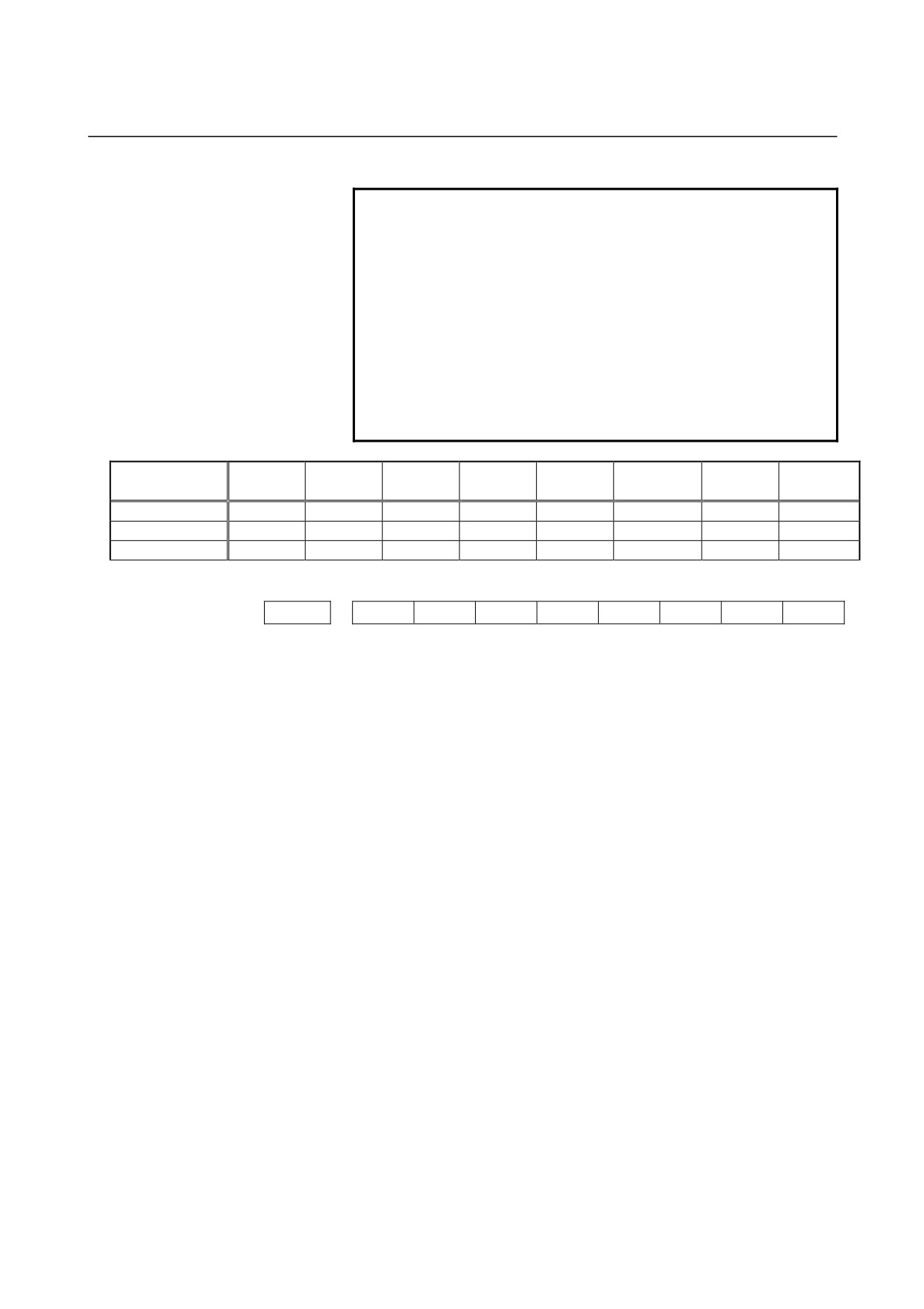
2 By setting the parameter No.27003, the following
parameters related to display are set
autoimatically.
No.14702#1
No.27000#1
No.27000#4
No.27100#4
No.27000#6
No.27001#0,#1
No.27004#0
No.27004#1
Spindl select
Hole select
Face pos-M
Face pos-T
Coord conv
Rot. axis nam
Menu 1
Menu 2
No.27003 #0=1
0
0
0
0
1
0
1
0
No.27003 #1=1
0
0
0
0
0
0
0
0
No.27003 #2=1
0
0
0
0
0
0
0
0
#7
#6
#5
#4
#3
#2
#1
#0
27004
MM2
MM1
MM0
If the machine configuration does not meet the parameter No.27003 or
No.27103, this parameter is used to display the optimum menu on the
screen.
MM0
1 :
The following menus are displayed.
•
Hole Machining (G1000 to G1006) or (G1110 to G1114)
•
Facing (G1020 to G1021)
•
Contouring (G1030 to G1033)
•
Pocketing (G1040 to G1043)
•
Grooving (G1050 to G1053)
•
XY-plane : Free figure (G1200 to G1206)
•
XY-plane : Hole position (G1210 to G1217)
•
XY-plane : Fixed form figure (G1220 to G1223)
MM1
1 :
The following menus are displayed.
•
Hole Machining (G1000 to G1006) or (G1110 to G1114)
•
Facing (G1020 to G1021)
•
Contouring (G1030 to G1033)
•
Pocketing (G1040 to G1043)
•
Grooving (G1050 to G1053)
•
C-axis Grooving (G1056)
•
XC-plane : Free figure (G1500 to G1506)
•
XC-plane : Fixed form figure (G1520 to G1523)
•
XC-plane : C-axis figure (G1570 to G1573)
•
ZC-plane : Free figure (G1600 to G1606)
•
ZC-plane : C-axis figure (G1670 to G1673)
- 780 -

B-63874EN/05
APPENDIX
A.PARAMETERS
MM2
1 :
The following menus are displayed.(It is effective only at MM0 = 1.)
•
Hole Machining (G1000 to G1006) or (G1110 to G1114)
•
Facing (G1020 to G1021)
•
Contouring (G1030 to G1033)
•
Pocketing (G1040 to G1043)
•
Grooving (G1050 to G1053)
•
XA-plane : Free figure (G1700 -> G1706)
•
XA-plane : A-axis figure (G1770 -> G1773)
NOTE
1 When these parameter are all 0, the all milling
cycle menu except the menu of XA plame are
displayed on the screen
2 When the parameter No.27003 or No.27103 is set,
this parameter are initialize at the power ON and
pushing “F” key.
27005
CLMPM
CLMPM
0 :
M code for Main spindle C-axis clamping is not output.
≠0 :
M code for Main spindle C-axis clamping.
(Path-specific parameter)
Remark) refer to “III-1.10 C-axis Clamping M code Output”.
27006
UCLMPM
UCLMPM
0 :
M code for Main spindle C-axis unclamping is not output.
≠0 :
M code for Main spindle C-axis unclamping.
(Path-specific parameter)
Remark) refer to “III-1.10 C-axis Clamping M code Output”.
27007
CFCODM
CFCODM :
Feedrate to replace all rapid traverse feedrate during C-axis machining
for feed per minute.
If 0 is set, the feedrate is assumed 2000 (mm/min) or 78.7 (inch/min) .
Unit of data:
For metric input (0000#2=0) : 1(mm/min)
For inch input (0000#2=1) : 0.01(inch/min)
NOTE
In XC plane, Polar coordinate interpolation is
used. That is, it is impossible to use G0 command.
Therefore, No.27007 is used instead of rapid
traverse.
- 781 -
A.PARAMETERS
APPENDIX
B-63874EN/05
27008
CFCODR
CFCODR :
Feedrate to replace all rapid traverse feedrate during C-axis machining
for feed per revolution.
If 0 is set, the feedrate is assumed 2 (mm/min) or 0.0787 (inch/min).
Unit of data:
For metric input (0000#2=0) : 0.0001(mm/rev)
For inch input (0000#2=1) : 0.000001(inch/rev)
NOTE
In XC plane, Polar coordinate interpolation is
used. That is, it is impossible to use G0 command.
Therefore, No.27008 is used instead of rapid
traverse.
27009
CLERCLMP
CLERCLMP :
Minimum Clump value of the clearance for Milling cycles.
Unit of data:
For metric input (0000#2=0) : 0.001(mm)
For inch input (0000#2=1) : 0.0001(inch)
27010
APESCLMP
APESCLMP :
Minimum Clump value of Radius or Distance of Approach or Escape
for Milling cycles.
Unit of data:
For metric input (0000#2=0) : 0.001(mm)
For inch input (0000#2=1) : 0.0001(inch)
27011
CLMPMS
CLMPMS
0 :
M code for Sub spindle C-axis clamping is not output.
≠0 :
M code for Sub spindle C-axis clamping.
(Path-specific parameter)
Remark) refer to “1.10 C-axis Clamping M code Output”.
27012
UCLMPMS
UCLMPMS
0 :
M code for Sub spindle C-axis unclamping is not output.
≠0 :
M code for Sub spindle C-axis unclamping.
(Path-specific parameter)
Remark) refer to “1.10 C-axis Clamping M code Output”.
- 782 -

B-63874EN/05
APPENDIX
A.PARAMETERS
A.3.2 Parameters for Facing Cycles
These parameters are for the settings for facing cycles.
#7
#6
#5
#4
#3
#2
#1
#0
27030
FC1
FC0
FC0
0 : The input data item of [PATH MOVE METHOD] and [PATH MOVE
FEED RATE] are displayed on Facing cycle menu.
1 : The input data item of [PATH MOVE METHOD] and [PATH MOVE
FEED RATE] are not displayed on Facing cycle menu.
FC1
0 : all menu is displayed in “CUT SHIFT DIRECTION”.
1 : only the perpendicular direction to
“CUTTING DIRECTION” is
displayed in “CUT SHIFT DIRECTION”.
- 783 -
A.PARAMETERS
APPENDIX
B-63874EN/05
A.3.3
Parameters for Contouring Cycles
These parameters are for the settings for contouring cycles.
#7
#6
#5
#4
#3
#2
#1
#0
27040
CN6
CN4
CN3
CN2
CN1
CN0
CN0
0 :
During in-feed in Roughing, the tool moves by retracting to the height
of the top workpiece surface plus the clearance.
1 :
During in-feed in Roughing, the tool moves by retracting to the height
of the machining surface plus the clearance.
CN1
0 :
In Roughing, the tool moves at a hollow by retracting to the height of
the top workpiece surface plus the clearance.
1 :
In Roughing, the tool moves at a hollow by retracting to the height of
the machining surface plus the clearance.
CN2
0 :
In Roughing, the tool moves at an opening by retracting to the height
of the top workpiece surface plus the clearance..
1 :
In Roughing, the tool moves at an opening by retracting to the height
of the machining surface plus the clearance.
CN3
0 :
In side finishing, NC does not perform cutter compensation.
1 :
In side finishing, NC performs cutter compensation.
Remark) Tool path is not calculated with Cutter compensation in
inside, but G41 or G42 is outputted directly.
CN4
0 :
The system performs an interference check.
1 :
The system does not perform an interference check.
CN6
0 :
In Roughing, when the cutting start point is equal to the end point, the
tool cuts directly without escape to the radius direction.
1 :
In Roughing, when the cutting start point is equal to the end point, the
tool cuts with escape to the radius direction.
27045
COFSW
COFSW :
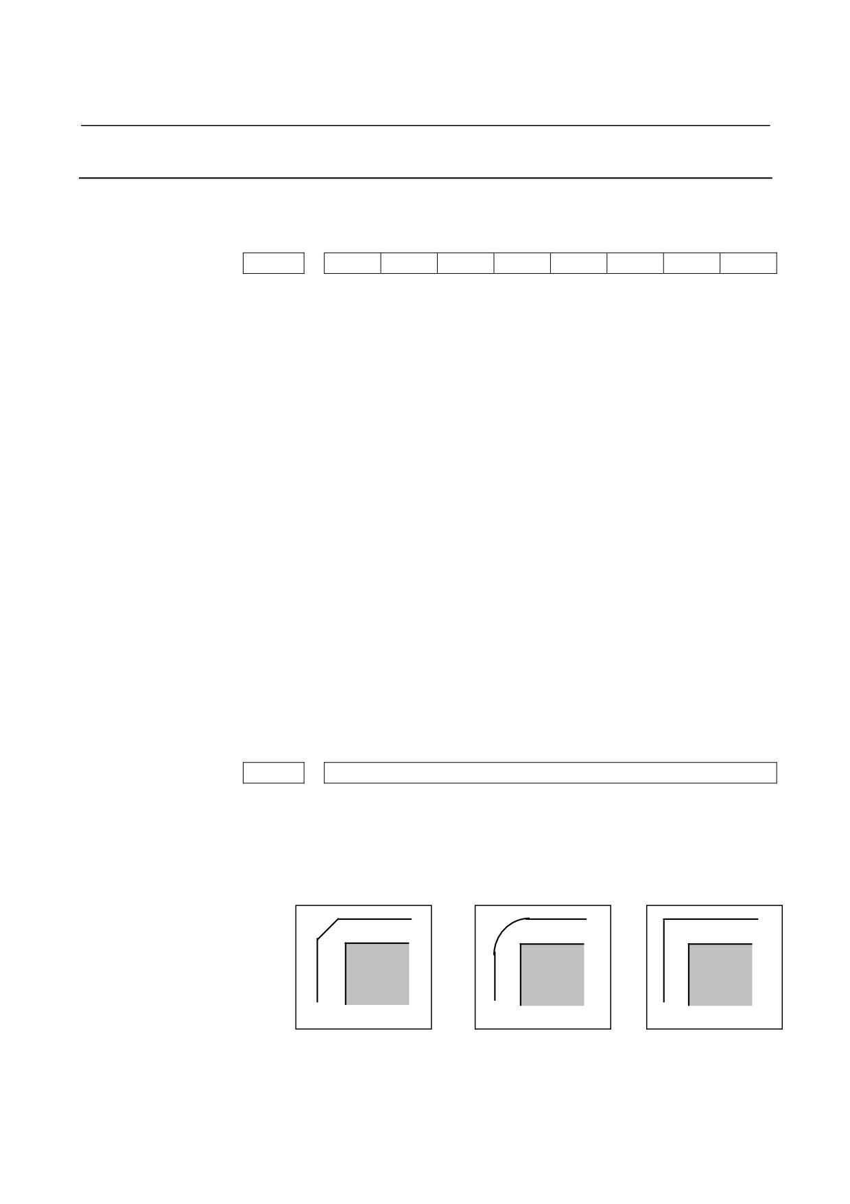
Offset method for side finishing and chamfering in contouring.
=0 :
Corner cut interpolation.
=1 :
Circular interpolation.
=2 :
Extended straight line.
0
1
2
- 784 -
B-63874EN/05
APPENDIX
A.PARAMETERS
27046
CMVFR
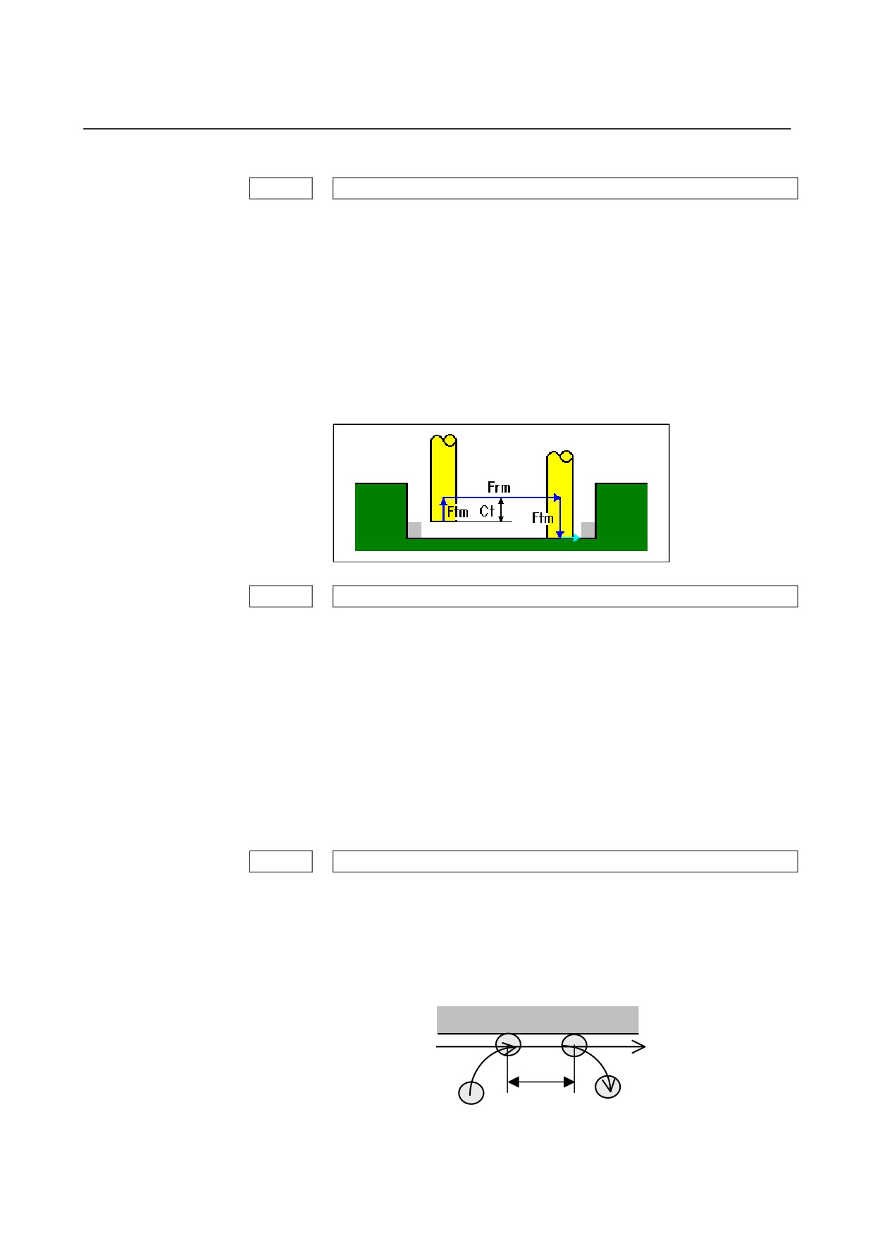
CMVFR : Feedrate during movement in the cutter radius direction in contouring.
For feed per minute.
If 0 is set, the feedrate is assumed Rapid traverse feedrate.
Unit of data:
For metric input (0000#2=0) : 1(mm/min)
For inch input (0000#2=1) : 0.01(inch/min)
Remark) Feedrate during movement in the cutter radius direction is
‘Frm’ as the following illustration.
27047
CMVFT
CMVFT : Feedrate during movement in the tool axis direction in contouring
for feed per minute.
If 0 is set, the feedrate is assumed Rapid traverse feedrate.
Unit of data:
For metric input (0000#2=0) : 1(mm/min)
For inch input (0000#2=1) : 0.01(inch/min)
Remark) Feedrate during movement in the tool axis direction is ‘Ftm’
as the above illustration.
27048
CVOVL
CVOVL : Amount of overlapping for an approach/escape during contouring.
Unit of data :
For metric input (0000#2=0) : 0.001(mm)
For inch input (0000#2=1) : 0.0001(inch)
CVOVL
- 785 -
A.PARAMETERS
APPENDIX
B-63874EN/05
27049
CMVFR
CMVFR :
Feedrate during movement in the cutter radius direction in contouring
for feed per revolution.
If 0 is set, the feedrate is assumed Rapid traverse feedrate.
Unit of data:
For metric input (0000#2=0) : 0.0001(mm/rev)
For inch input (0000#2=1) : 0.000001(inch/rev)
Remark) Refer to No.27046.
27050
CMVFT
CMVFT :
Feedrate during movement in the tool axis direction in contouring
for feed per revolution.
If 0 is set, the feedrate is assumed Rapid traverse feedrate.
Unit of data:
For metric input (0000#2=0) : 0.0001(mm/rev)
For inch input (0000#2=1) : 0.000001(inch/rev)
Remark) Refer to No.27047.
- 786 -
B-63874EN/05
APPENDIX
A.PARAMETERS
A.3.4 Parameters for Pocketing Cycles
These parameters are for the settings for pocketing cycles.
#7
#6
#5
#4
#3
#2
#1
#0
27060
PR7
PR6
PR5
PR4
PR3
PR2
PR2
PR0
PR0
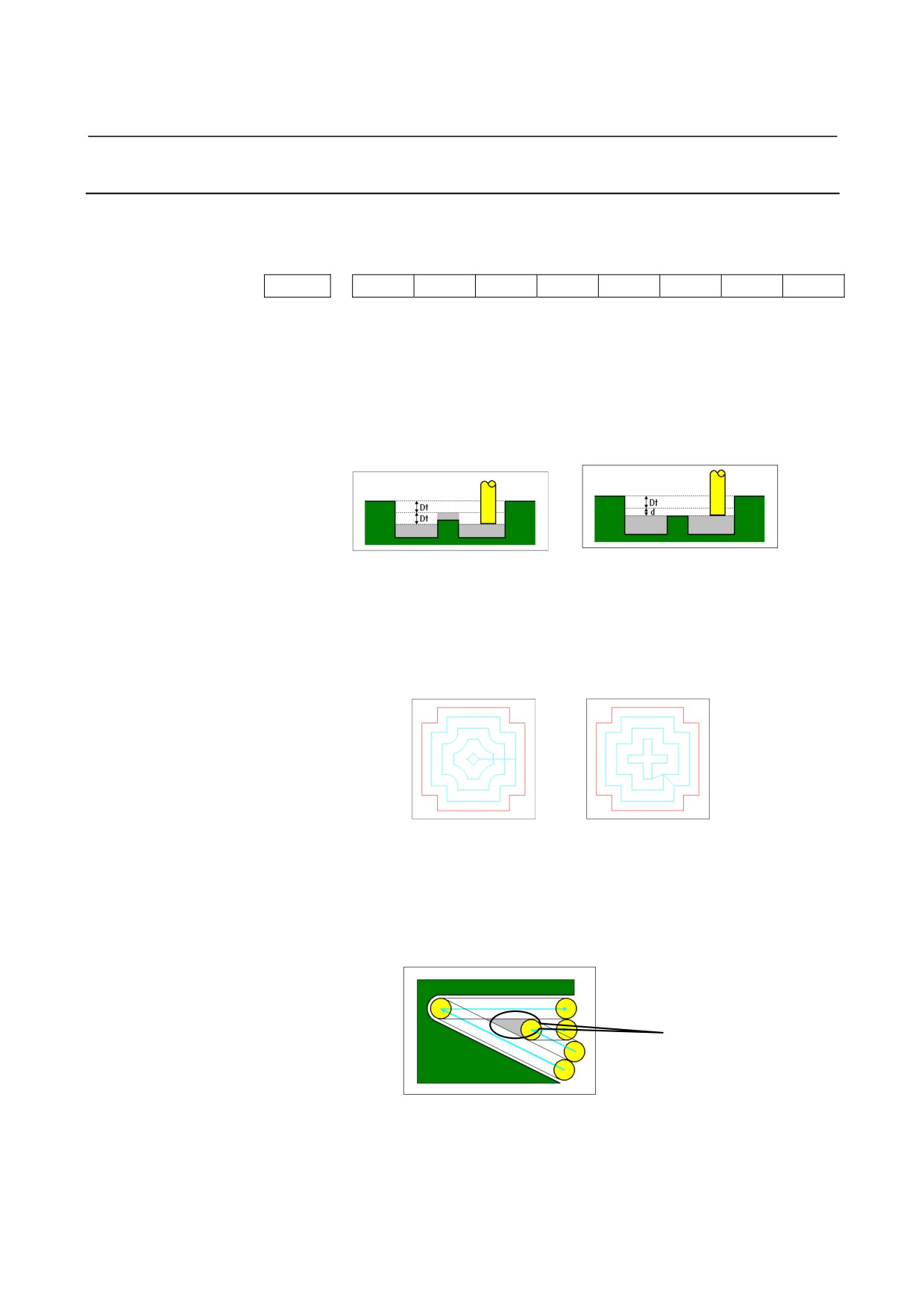
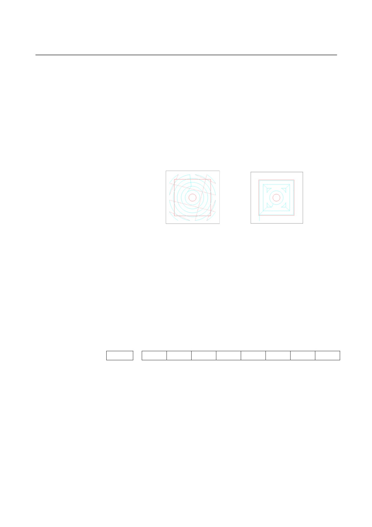
0 : Machining starts on the inside during roughing and bottom finishing.
1 : Machining starts on the outside during roughing and bottom finishing.
PR1
0 : The top of an island is not machined during roughing and bottom
finishing.
1 : Machining is performed by controlling the depth of cut during
roughing and bottom finishing.
PR1 = 0
PR1 = 1
PR2
0 : Method of interpolation during roughing and bottom finishing
(interpolation of elements with arcs).
1 : Method of interpolation during roughing and bottom finishing
(interpolation of elements by extending them).
PR2 = 0
PR2 = 1
PR3
0 : Method of machining portions left uncut during roughing and bottom
finishing (no machining of portions left uncut).
1 : Method of machining portions left uncut during roughing and bottom
finishing (machining of portions left uncut).
UNCUT
- 787 -
A.PARAMETERS
APPENDIX
B-63874EN/05
PR4
0 : The tool moves by retracting to the height of the top workpiece
surface plus the clearance at an opening during roughing and bottom
finishing.
1 : The tool moves by retracting to the height of the machining surface
plus the clearance at an opening during roughing and bottom
finishing.
PR5
0 : Paths for all material elements are created with an island reference
during roughing and bottom finishing.
1 : Paths for all material elements are created with a pocket reference
during roughing and bottom finishing.
PR5 = 0
PR5 = 1
PR6
0 : The tool moves by retracting to the height of the top workpiece
surface plus the clearance during movement in the tool axis direction
during roughing and bottom finishing.
1 : The tool moves by retracting to the height of the machining surface
plus the clearance during movement in the tool axis direction during
roughing and bottom finishing.
PR7
0 : The input data item of [START PT.(1st AXIS)] and [START PT.(2nd
AXIS)] are not displayed on the Pocketing cycle menu..
1 : The input data item of [START PT.(1st AXIS)] and [START PT.(2nd
AXIS)] are displayed on the Pocketing cycle menu..
#7
#6
#5
#4
#3
#2
#1
#0
27061
PF4
PF3
PF2
PF1
PF0
PF0
0 : During in-feed in side finishing and chamfering, the tool moves by
retracting to the height of the top workpiece surface plus the
clearance.
1 : During in-feed in side finishing and chamfering, the tool moves by
retracting to the height of the machining surface plus the clearance.
PF1
0 : In side finishing and chamfering, the tool moves at a hollow by
retracting to the height of the top workpiece surface plus the
clearance.
1 : In side finishing and chamfering, the tool moves at a hollow by
retracting to the height of the machining surface plus the clearance.
- 788 -
B-63874EN/05
APPENDIX
A.PARAMETERS
PF2
0 : In side finishing and chamfering, the tool moves at an opening by
retracting to the height of the top workpiece surface plus the
clearance.
1 : In side finishing and chamfering, the tool moves at an opening by
retracting to the height of the machining surface plus the clearance.
PF3
0 : In side finishing, NC does not perform cutter compensation.
1 : In side finishing, NC performs cutter compensation.
Remark) Tool path is not calculated with Cutter compensation in
inside, but G41 or G42 is outputted directly.
PF4
0 : The system performs an interference check.
1 : The system does not perform an interference check.
27065
POFSW
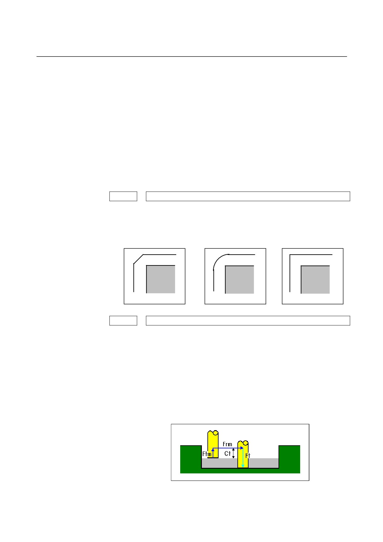
POFSW : Offset method for side finishing and chamfering in pocketing.
= 0 : Corner cut interpolation.
= 1 : Circular interpolation.
= 2 : Extended straight line.
0
1
2
27066
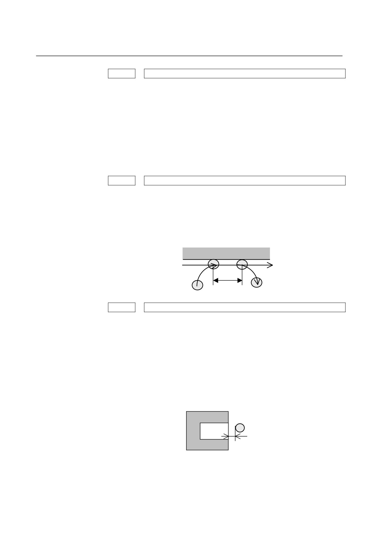
PKTFR
PKTFR : Feedrate during movement in the cutter radius direction in in-feed for
feed per minute.
If 0 is set, the feedrate is assumed Rapid traverse feedrate.
Unit of data:
For metric input (0000#2=0) : 1(mm/min)
For inch input (0000#2=1) : 0.01(inch/min)
Remark) Feedrate during movement in the cutter radius direction is
‘Frm’ as the following illustration.
- 789 -
A.PARAMETERS
APPENDIX
B-63874EN/05
27067
PKTFT
PKTFT : Feedrate during movement in the tool axis direction in in-feed for feed
per minute.
If 0 is set, the feedrate is assumed Rapid traverse feedrate.
Unit of data:
For metric input (0000#2=0) : 1(mm/min)
For inch input (0000#2=1) : 0.01(inch/min)
Remark) Feedrate during movement in the tool axis direction is ‘Ftm’
as the above illustration.
27068
PKOVL
PKOVL : Amount of overlapping for an approach/escape during side finishing
and chamfering.
Unit of data :
For metric input (0000#2=0) : 0.001(mm)
For inch input (0000#2=1) : 0.0001(inch)
PKOVL
27069
OPNCR
OPNCR : Clearance for an open portion in pocketing
(When OPNCR = 0)
For metric input (0000#2=0), the clearance for the open portion
is assumed to be 3 mm.
For inch input (0000#2=1), the clearance for the open portion is
assumed to be 0.3 inch.
Unit of data :
For metric input (0000#2=0) : 0.001(mm)
For inch input (0000#2=1) : 0.0001(inch)
OPNCR
- 790 -
B-63874EN/05
APPENDIX
A.PARAMETERS
27070
PKTFR
PKTFR : Feedrate during movement in the cutter radius direction in in-feed for
feed per revolution.
If 0 is set, the feedrate is assumed Rapid traverse feedrate.
Unit of data:
For metric input (0000#2=0) : 0.0001(mm/rev)
For inch input (0000#2=1) : 0.000001(inch/rev)
Remark) Refer to No.27066.
27071
PKTFT
PKTFT : Feedrate during movement in the tool axis direction in in-feed for feed
per revolution.
If 0 is set, the feedrate is assumed Rapid traverse feedrate.
Unit of data:
For metric input (0000#2=0) : 0.0001(mm/rev)
For inch input (0000#2=1) : 0.000001(inch/rev)
Remark) Refer to No.27067.
- 791 -