FANUC MANUAL GUIDE i. OPERATOR’S MANUAL - page 25
2.LATHE
EXAMPLE OF PROGRAMMING
B-63874EN/05
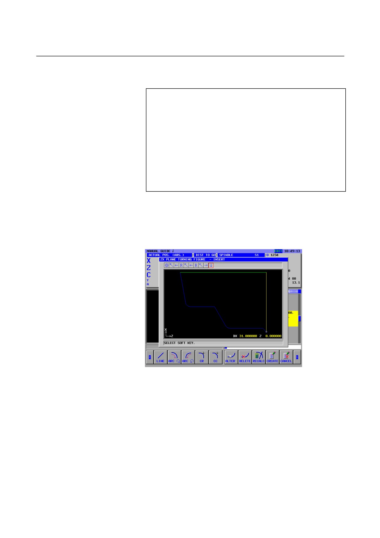
In this programming example, round bar workpiece is used. So, enter
the blank figure as follows.
(ZX PLANE TURNING FIGURE - INSERT)
[LINE]
(LINE - INSERT)
[RIGHT]
(LINE DIRECTION)
0 INPUT
(END POINT Z)
→
<ATTRIBUTE>
[BLANK]
(ELEMENT TYPE)
[OK]
[LINE]
(LINE - INSERT)
[DOWN]
(LINE DIRECTION)
31 INPUT
(END POINT DX)
[OK]
Part figures are displayed in blue line, blank figures are displayed in
green line, and the currently selected figure is displayed in yellow
line.
Check the entered part figures and blank figures are correct by
comparing with the blue print, then register them as figure blocks into
CNC memory finally.
- 702 -
B-63874EN/05
EXAMPLE OF PROGRAMMING
2.LATHE
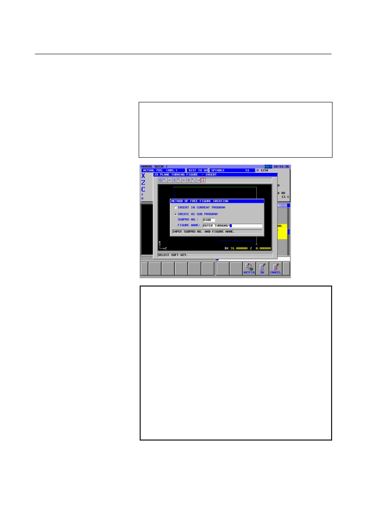
Figure blocks can be registered into the current part program directly,
and also can be registered as another sub program.
Registered figure blocks can be used also for finishing, so in this
example, register them as a sub program.
(ZX PLANE TURNING FIGURE - INSERT)
[CREATE]
(METHOD OF FREE FIGURE CREATION)
↓
<CREATE AS SUB PROGRAM>
8100 INPUT
(SUBPRO NO.)
OUTER TURNING
(FIGURE NAME)
[OK]
NOTE
Registered sub program can be displayed in a figure
menu tab, “SUBPROGRAM”.
In this case, set the parameters No14720 to 14723
in advance.
For this example, set those parameters as follow.
No.14720=8000 (Minimum program number of sub
programs displayed in the turning
machining sub program menu)
No.14721=8499 (Maximum program number of sub
programs displayed in the turning
machining sub program menu)
No.14722=8500 (Minimum program number of sub
programs displayed in the milling
machining sub program menu)
No.14723=8999 (Maximum program number of sub
programs displayed in the milling
machining sub program menu)
- 703 -

2.LATHE
EXAMPLE OF PROGRAMMING
B-63874EN/05
2.5.5
Entering Tool Changing and Spindle Rotation Blocks for
Outer Finishing in ISO-code Form
Before starting the 2nd process of outer finishing, change tool to the
finishing tool (T0202), spindle rotation, and other necessary blocks in
ISO-code form with G-code and so on.
G28 U0 W0 ; INSERT
(Reference position return)
T0202 ; INSERT
(Tool change)
G99 G96 S300 ; INSERT
(Constant surface speed control, mm/rev mode)
M03 ; INSERT
(Spindle rotation)
G00 X120. Z20. ; INSERT
(Approaching)
Otherwise, you can enter them from the fixed form sentence menu.
(Soft-key group for Turning cycle menu)
[START]
<START>
↓
<<1.START PROCEDURE>>
[INSERT]
NOTE
There may be a case that undefined value is
entered by “?” in the fixed form sentence menu, so
in this case, you need to replace the “?” by proper
value can be used in actual machining.
- 704 -
B-63874EN/05
EXAMPLE OF PROGRAMMING
2.LATHE
2.5.6
Entering Outer Finishing Cycle Machining Process
2.5.6.1 Entering figure for outer finishing cycle block
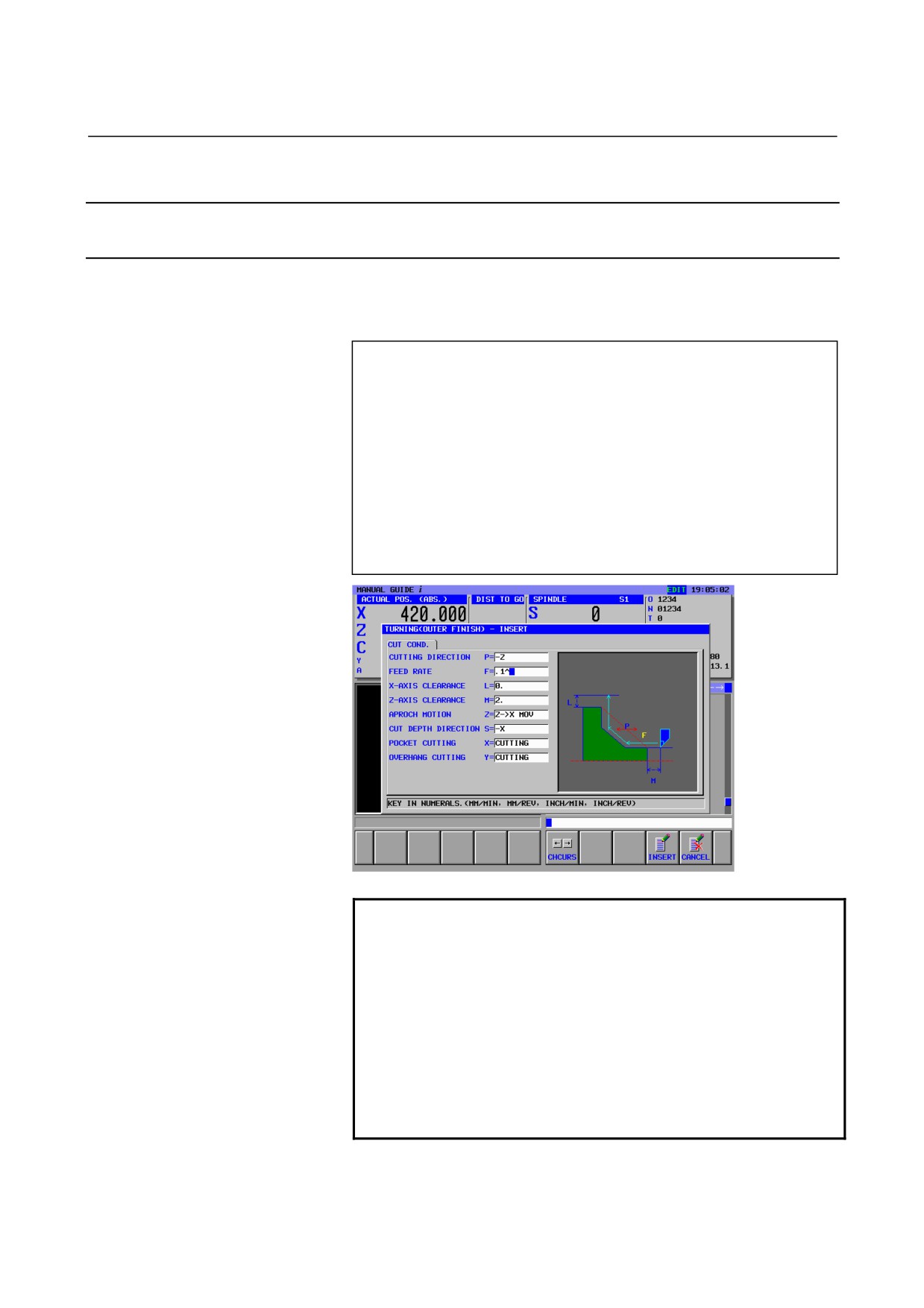
Enter the 2nd process : outer finishing by a general purpose finishing
tool (T0202).
Enter machining type, cutting condition and so on.
(Soft-key group for Turning cycle menu)
[CYCLE]
→
<TURNING>
↓
↓
<<7.TURNING(OUTER FINISH)>>
[SELECT]
(TURNING(OUTER FINISH) - INSERT)
<CUT COND.>
[-Z]
(CUTTING DIRECTION)
.1 INPUT
(FEEDRATE)
[INSERT]
NOTE
1 In the cycle machining data menu window, all data
excepting cutting condition data are set
automatically. However, the data entered at
previously entered cycle of same kind are copied,
so you must enter the data if you have not entered
the same kind of cycle.
2 When you select the cycle machining type form
cycle machining menu, instead of selecting by the
cursor, you can use direct inputting of item number
and INPUT. (In this case, enter 7 INPUT)
- 705 -
2.LATHE
EXAMPLE OF PROGRAMMING
B-63874EN/05
2.5.6.2 Entering figure for outer finishing
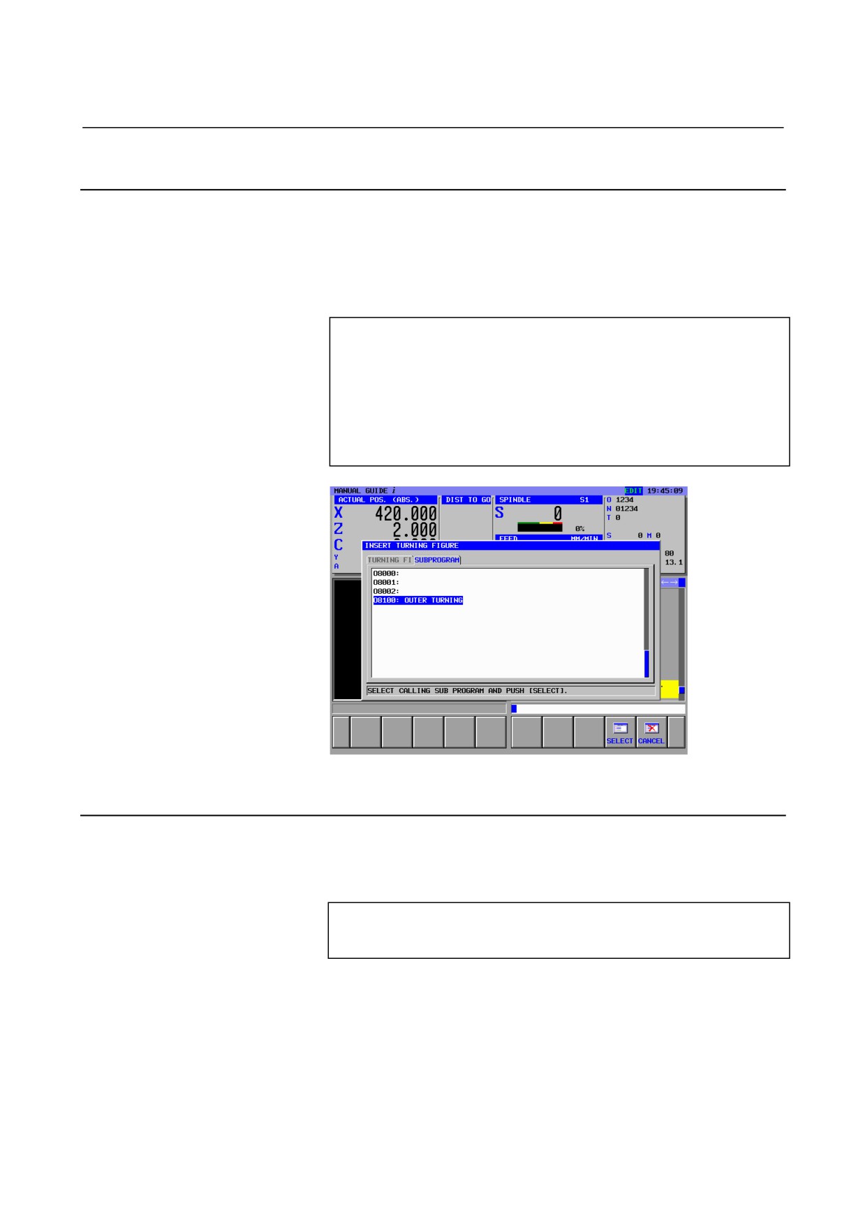
By inserting the outer finishing cycle machining block, the window
for free form entering is displayed, so enter the final figure of
machining. But, the former registered figure blocks for roughing can
be used, so push [CANCEL] and go back to the turning figure menu
window, then select from the sub program menu.
(ZX PLANE TURNING FIGURE - INSERT)
(START POINT - INSERT)
[CANCEL]
(INSERT TURNING FIGURE)
→
<SUBPROGRAM>
↓
<<08100: OUTER TURNING>>
[SELECT]
2.5.6.3 Entering releasing motion blocks in ISO-code form
After outer finishing, return the tool to safety area before the next
C-axis drilling process.
Enter these motion blocks in form of ISO-code with such as G-code.
G00 X200. ; INSERT
(Releasing motion)
M05 ; INSERT
(Spindle stop)
G28 U0 W0 ; INSERT
(Reference position return)
- 706 -

B-63874EN/05
EXAMPLE OF PROGRAMMING
2.LATHE
2.5.7
Entering Tool Changing and Spindle Rotating Blocks for
C-axis Drilling
2.5.7.1 Entering in ISO-code form directly
Enter blocks of tool changing, C-axis mode changing spindle rotation
approaching and releasing for C-axis drilling. You can enter these
blocks using ISO-code form.
M21. ; INSERT
(Change to C-axis mode)
T0303 ; INSERT
(Tool change)
G98 G97 ; INSERT
(mm/min mode)
M03 S800 ; INSERT
(Spindle rotation)
G00 X120. Z20. ; INSERT
(Approaching)
2.5.7.2 Entering by fixed form sentence menu
ISO-code form part program can be entered from the fixed form
sentence menu. But, in such a case, proper fixed form sentence must
be prepared in advance.
(Soft-key group for Milling cycle menu)
[START]
<START>
↓
<<2.C-AXIS MILLING START>>
[INSERT]
NOTE
There may be a case that undefined value is
entered by “?” in the fixed form sentence menu, so
in this case, you need to replace the “?” by proper
value can be used in actual machining.
- 707 -
2.LATHE
EXAMPLE OF PROGRAMMING
B-63874EN/05
2.5.8
Entering C-axis Drilling Process
2.5.8.1
Entering C-axis drilling cycle block
Enter the 3rd process : C-axis end face drilling by the drilling tool
(T0303).
Enter machining type, cutting condition and so on.
(Soft-key group for Milling cycle menu)
[CYCLE]
<HOLE MACH.>
↓
<<2.DRILLING>>
[SELECT]
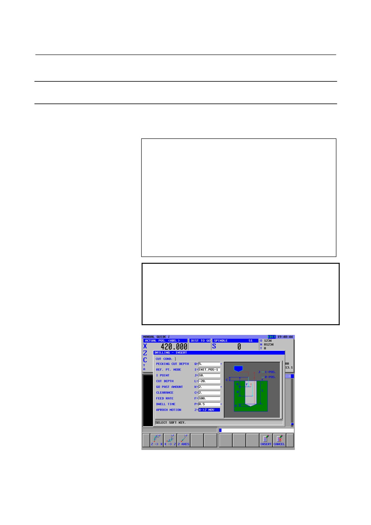
(DRILLING - INSERT)
<CUT COND.>
5 INPUT
(PECKING CUT DEPTH)
INPUT
(REF.PT.MODE)
10 INPUT
(I POINT)
-20 INPUT
(CUT DEPTH)
2 INPUT
(GO PAST AMOUNT)
2 INPUT
(CLEARANCE)
100 INPUT
(FEEDRATE)
.5 INPUT
(DWELL TIME)
[INSERT]
NOTE
In the cycle machining data menu window, all data
excepting cutting condition data are set
automatically. However, the data entered at
previously entered cycle of same kind are copied,
so you must enter the data if you have not entered
the same kind of cycle.
- 708 -
B-63874EN/05
EXAMPLE OF PROGRAMMING
2.LATHE
2.5.8.2 Entering hole position block
By inserting the drilling cycle block, the window of hole position
menu is displayed, so select the “Arc point” item.
(INSERT MILLING FIGURE)
<HOLE POSI.>
↓
↓
<<17.C-AXIS HOLE ON FACE (ARC POINTS)>>
[SELECT]
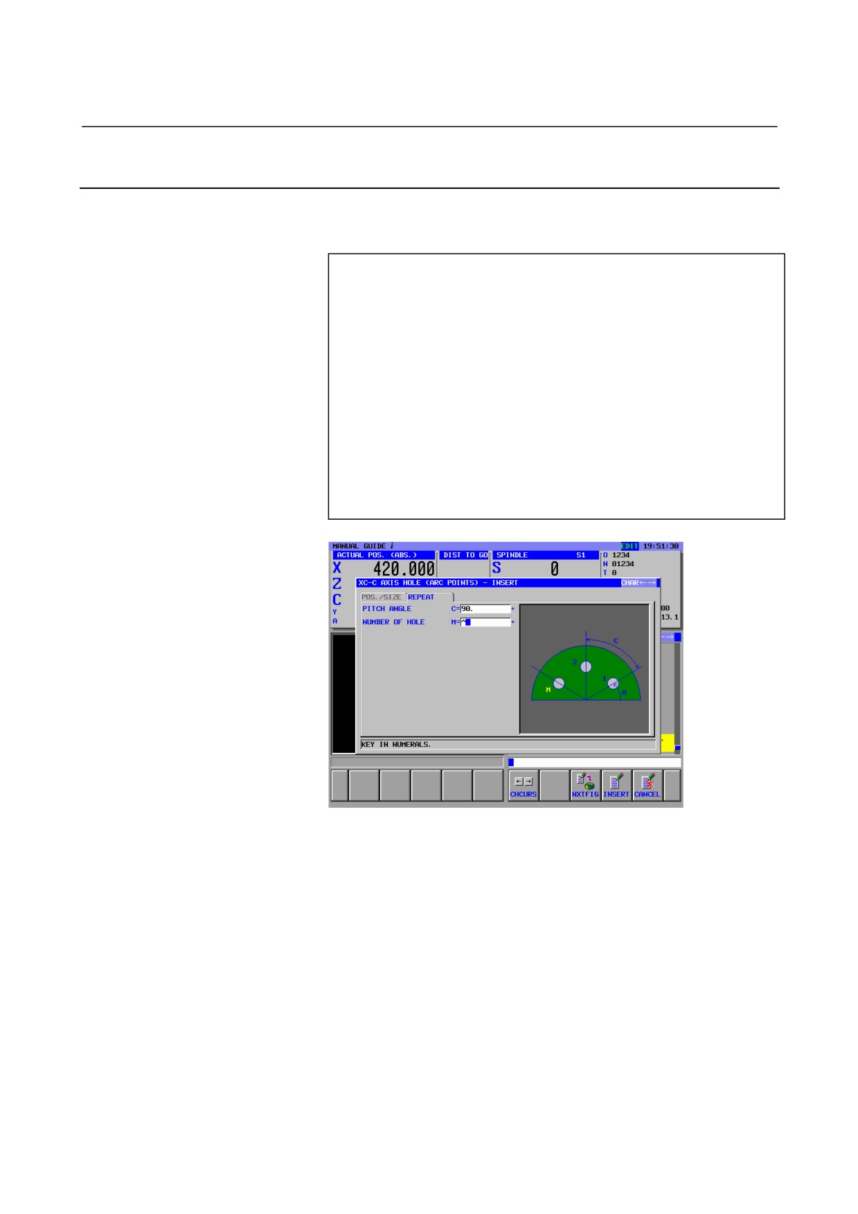
(XC-C AXIS HOLE (ARC POINTS) - INSERT)
<POS./SIZE>
0 INPUT
(BASE POSITION)
11 INPUT
(X AXIS POS.(RAD.))
0 INPUT
(START ANGLE)
→
<REPEAT>
90 INPUT
(PITCH ANGLE)
4 INPUT
(NUMBER OF HOLE)
[INSERT]
- 709 -

2.LATHE
EXAMPLE OF PROGRAMMING
B-63874EN/05
2.5.9
Operations in the “END” Menu
All necessary machining program have been entered, so enter end
procedure.
2.5.9.1
Entering in ISO-code form directly
Enter blocks for spindle stop, releasing and end M-code in ISO-code
form with G-code and son on.
M05. ; INSERT
(Spindle stop)
G00 X200. ; INSERT
(Releasing motion)
G28 U0 W0 ; INSERT
(Reference position return)
M02 ; INSERT
(End M-code)
2.5.9.2
Entering by fixed form sentence menu
ISO-code form part program can be entered from the fixed form
sentence menu. But, in such a case, proper fixed form sentence must
be prepared in advance.
(Soft-key group for Milling cycle menu)
[END]
<END>
↓
<<1.PROGRAM END>>
[INSERT]
NOTE
There may be a case that undefined value is
entered by “?” in the fixed form sentence menu, so
in this case, you need to replace the “?” by proper
value can be used in actual machining.
- 710 -
B-63874EN/05
EXAMPLE OF PROGRAMMING
2.LATHE
2.6
CHECKING OF THE PART PROGRAM
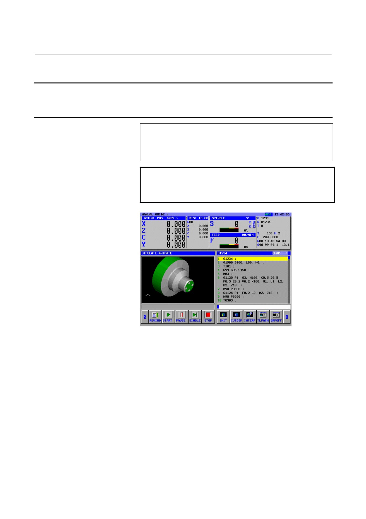
You can check the entered part program by animation.
2.6.1
Checking by Animation
Select MEM mode by using a mode-selecting switch on a machine-operating panel
[SIMLAT]
(SIMULATE - ANIMATE)
[REWIND]
[START]
NOTE
After checking by animation, in order to do other
operation, you must close the animation window by
pushing [GRPOFF] always.
- 711 -
3.MACHINING CENTER
EXAMPLE OF PROGRAMMING
B-63874EN/05
3
MACHINING CENTER
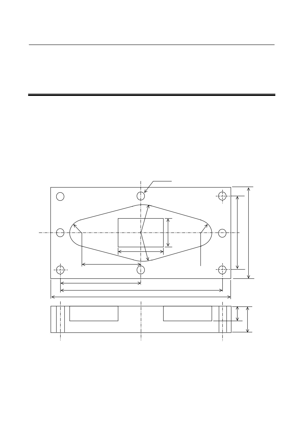
Example) Outer wall contouring, Pocketing, Drilling
Workpiece : 90×130×30
1st Process : Outer wall contouring by Flat end mill
(T01)
2nd Process: Pocket roughing by Flat end mill (T01)
3rd Process : Pocket finishing by Flat end mill
(T02)
(side, bottom)
4th Process : Drilling by Drill tool (T03)
φ4
R30
R15
70
80
15
30
35
55
110
120
10
20
- 712 -
B-63874EN/05
EXAMPLE OF PROGRAMMING
3.MACHINING CENTER
3.1
SETTING OF TOOL LENGTH OFFSET DATA
WARNING
1 Operation of tool offset setting varies from one
machine model to another. So operations described in
this section may differ from those ion actual machine.
As to the actual operation of tool offset setting on the
actual machine, refer to the applicable manual
supplied by the respective machine tool builders for
details.
If the set data does not match the characteristic of a
specific machine, the tool may bump against the
workpiece, and the machine may be forced to perform
unnatural machining, possibly causing damage to the
tool and/or machine, and even injuries.
2 As to the operations on a machine described in this
chapter, refer to the applicable manual supplied by the
respective machine tool builders for details.
If the operation does not match the characteristic of a
specific machine, the tool may bump against the
workpiece, and the machine may be forced to perform
unnatural machining, possibly causing damage to the
tool and/or machine, and even injuries.
Assume that the Z=0 position of the workpiece coordinate is the
surface of the workpiece, while the Z=0 position of the machine
coordinate is the machine origin.
By setting the distance between these 2 points to the tool length offset
data, workpiece coordinate of Z-axis can be defined.
Tool length is different between each tool for the actual machining, so
set the offset data respectively.
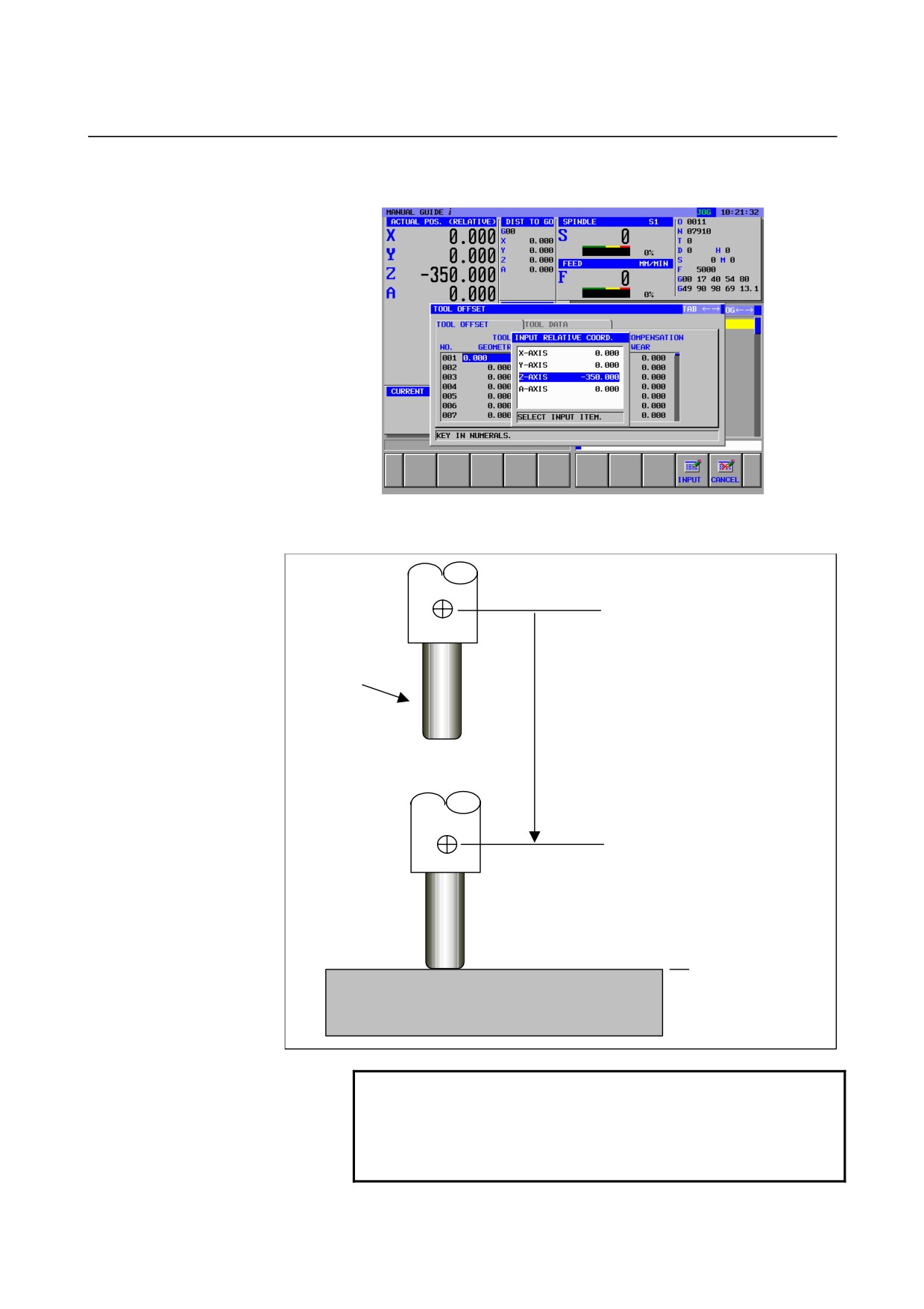
The tool length offset value is the relative coordinate value of Z-axis
at the point where the tool tip is touched to the surface of the
workpiece.
(1) Select the tool used for actual machining by switch on the
machine operator’s panel.
(2) Execute the machine reference position return of Z-axis.
(3) Press [ACTPOS] and make the relative coordinate data display.
(4) Press [PRESET], then push [ALL 0], and press [ALTER], then
the relative coordinate value of all axes are reset to 0. But, the
Z-axis coordinate only is used for measuring.
(5) Press [T-OFS] and make the tool offset widow open.
(6) Make the tool tip touch at the surface of the workpiece by JOG or
Manual handwheel. Then, the distance from the machine origin is
displayed as the Z-axis relative coordinate value.
(7) Select the tool length compensation column of the tool used for
measuring by moving the cursor by cursor key.
- 713 -
3.MACHINING CENTER
EXAMPLE OF PROGRAMMING
B-63874EN/05
(8) Pressing [INP.C.] displays the window of INPUT RELATIVE
COORD. window, then move the cursor to the Z-axis.
(9) Pressing
[INPUT] makes the Z-axis relative coordinate value
enter as the tool offset length data.
Z=0 (Machine coordinate)
The tool used
for actual
machining
This distance is set as the tool
length offset value
Z=0 (Workpiece
coordinate)
Workpiece
NOTE
There is a case such as using a sensor called base
master instead of touching the tool to the workpiece
surface, so into details and actual operations, refer
to the manual made by machine tool builder.
- 714 -
B-63874EN/05
EXAMPLE OF PROGRAMMING
3.MACHINING CENTER
3.2
SETTING OF WORKPIECE ORIGIN OFFSET VALUE
After setting the geometry offset data for necessary tools, set the
workpiece origin on the actual workpiece used for machining.
In order to carry out the actual machining by using the part program
made on the workpiece coordinate, set the distance between machine
coordinate and workpiece coordinate to the workpiece coordinate
system as the workpiece origin offset value.
In this section, operations, of which setting the center of the
workpiece (90x130) as the workpiece origin of X/Y/Z-axis by using
standard too with the radius 5mm, are described.
And, G54 is used as the workpiece coordinate system.
(1) Select the standard tool by using the switch on the machine
operator’s panel. There is a case of using special tool such as the
centering lever as the standard tool for easy operations and high
precision accuracy, so refer to the manual made by machine tool
builder for actual operations.
(2) After then, for safety, take measure to keep fully safety such as
closing the machine door.
(3) Select the manual handwheel mode on the machine operator’s
panel, and make the standard tool touch to the right side of the
workpiece
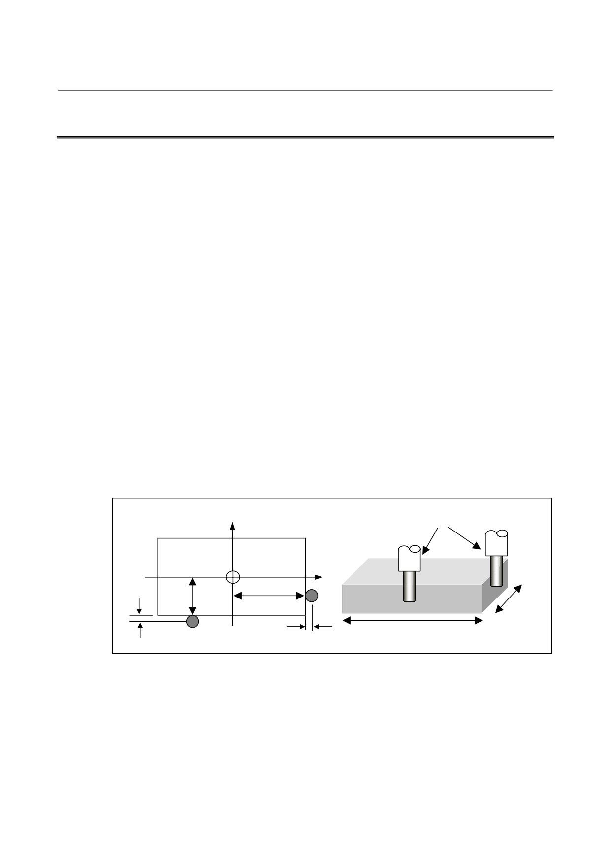
(A-position in the drawing) by referencing the
following drawing. At this time, make a spindle rotate by fully
safety speed if necessary, then you can avoid over-cutting by
stopping the tool moving at the position the tool begins cutting.
As to actual operations, refer to the manual made by the machine
tool builder.
Y
Standard tool
X
65
45
5
A
Y-axis
direction
B
5
X-axis direction
90mm
130mm
(4) Pressing
[WK SET] displays the window of the workpiece
coordinate system.
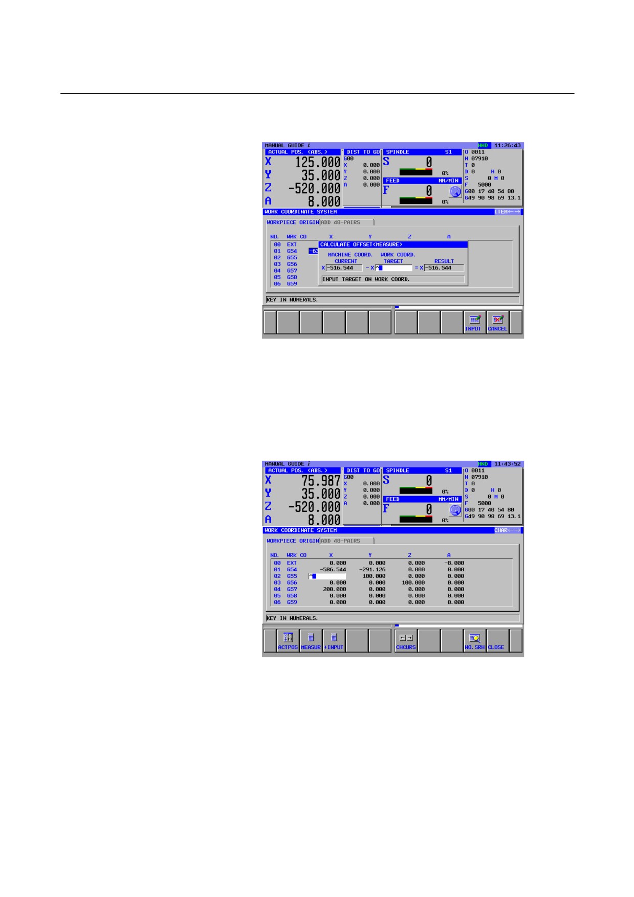
(5) Select the G54 X-axis data by moving the cursor. When other tab
is displayed in the window, the cursor motion type might be the
tab transition type, so press
[CHCURS] for changing to item
transition type of cursor.
- 715 -
3.MACHINING CENTER
EXAMPLE OF PROGRAMMING
B-63874EN/05
(6) Pressing [MEASUR] displays the window of offset calculating.
(7) When the tool touches to the right side of the workpiece, the
X-axis position should be X=70.0mm, 65mm of the right side
position + 5mm of the tool radius, so enter 70.0 to the target
workpiece coordinate value. Then, the calculation result value is
displayed at the RESULT column, so confirm the result is correct.
(8) Pressing
[INPUT] sets the above calculated value to the
workpiece origin offset data.
(9) Release the tool from the workpiece once, and set the Y-axis
workpiece origin offset data by similar operations of (3) to (8). In
this case, touch the point B in the drawing and the entering target
value is Y=50.0mm.
- 716 -
B-63874EN/05
EXAMPLE OF PROGRAMMING
3.MACHINING CENTER
3.3
PREPARING OF THE FIXED FORM SENTENCE MENU
As to the fixed form sentence, machine tool builder usually sets the
suitable menu for specified respective machine. But, you can enter his
own menu on the MANUAL GUIDE i screen by yourself.
3.3.1
Entering the Fixed Form Sentence for Milling
Enter the fixed form sentence menu which will be called by the
soft-key [FIXFRM] in the soft-key group for milling.
Enter programs for START and END.
[SETTING]
(SETTING)
<BASIC>
↓
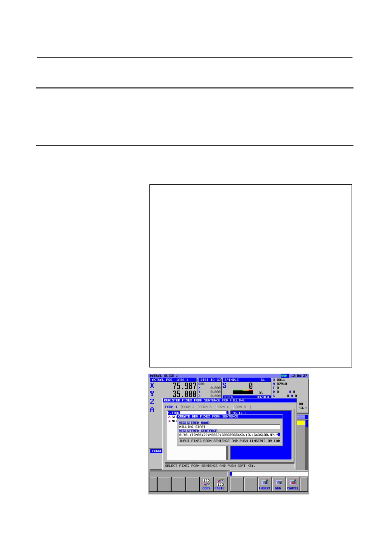
<<1. REGISTER FIXED FORM SENTENCE FOR MILLING>>
[SELECT]
(REGISTER FIXED FORM SENTENCE FOR MILLING)
<FORM 1>
[NEW]
(CRATE NEW FIXED FORM SENTENCE)
<REGISTERED NAME : >
MILLING START INPUT
<REGISTERED SENTENCE : >
G28 G91 Z0. ; G28 X0. Y0. ; T? M06 ; D? ; M03 S? ; G00 G90 G54 X0. Y0.; G43
Z100. H? ;
[ADD]
→
<FORM5>
[NEW]
(CREATE NEW FIXED FORM SENTENCE)
<REGISTERED NAME : >
PROGRAM END INPUT
<REGISTERED SENTENCE : >
M05. ; G00 G90 Z100. ; G28 G91 Z0, ; M06 T0 ;M30 ;
[ADD]
[TO MNU]
- 717 -
3.MACHINING CENTER
EXAMPLE OF PROGRAMMING
B-63874EN/05
3.4
SETTING OF THE TOOL DATA
Set the necessary tool data. These tool data are used for displaying
tool form of animation and calculation of cutting angle in the cycle
machining.
The tool length offset data were already set in section 3.1.
T01 : Flat end mill for roughing
T02 : Flat end mill for finishing
T03 : Drill
Display “TOOL OFFSET” window by [T-OFS]
TOOL OFFSET
NO.
TOOL LENGTH. COMP.
CUTTER COMPENSATOIN
GEOMETRY
WEAR
GEOMETRY
WEAR
001
Measured value
0.000
4.000
0.000
002
Measured value
0.000
3.000
0.000
003
Measured value
0.000
2.000
0.000
NOTE
1 The above offset data are just an example, and they
cannot be used for actual machining.
2 The above offset number 003 is used for drilling
tool, and if you use it for animation, you must set the
radius amount of the drill to radius offset data.
3 There is a case that the above offset screen might
not be displayed depending on the attached
optional function. Into details, refer to the manual
made by machine tool builder.
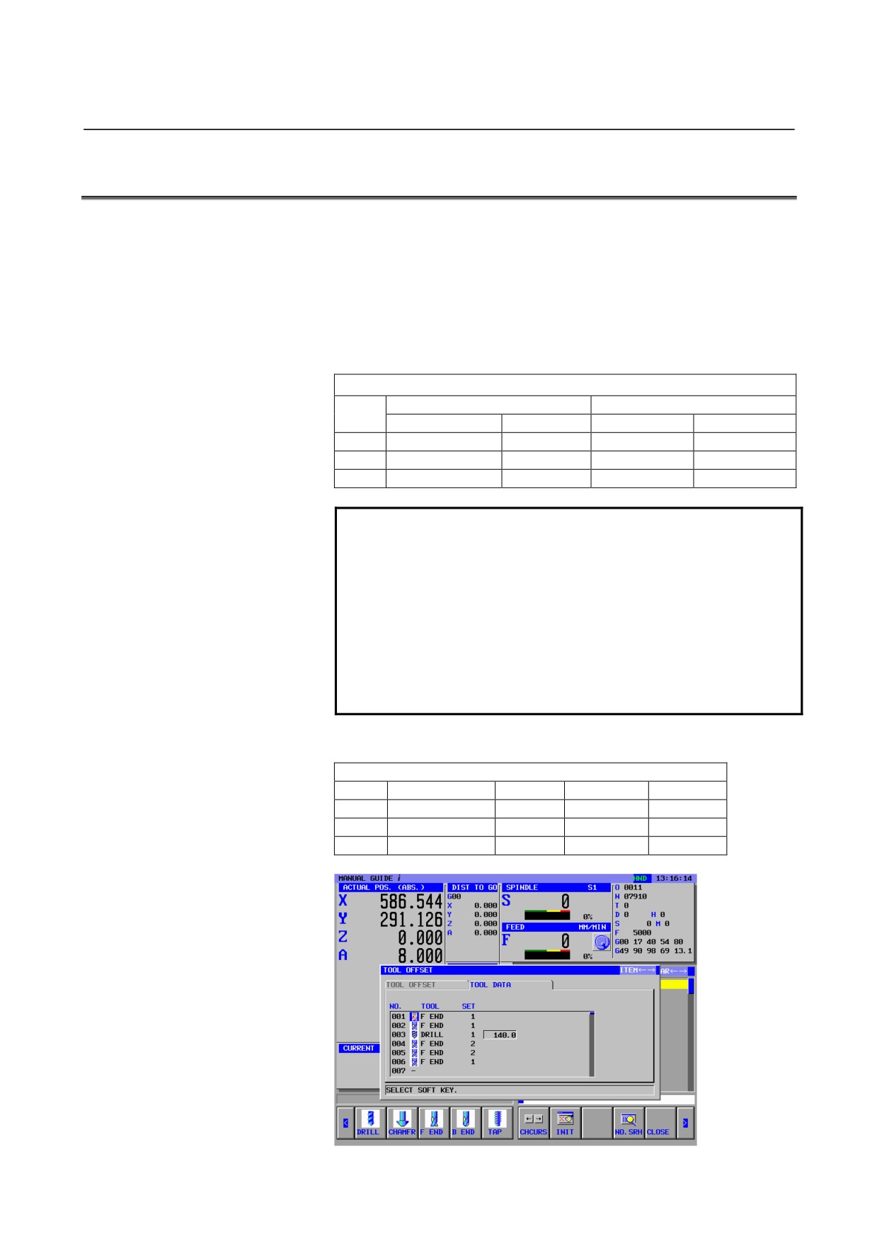
Display “TOOL DATA” tab by cursor key →
TOOL DATA
NO.
TOOL
SET
001
F END
1
002
F END
1
003
DRILL
1
140.0
- 718 -
B-63874EN/05
EXAMPLE OF PROGRAMMING
3.MACHINING CENTER
3.5
CREATING OF PART PROGRAM
In the MANUAL GUIDE i , background editing can be used, but in
this section, part program creating operations are described by using
foreground editing on the EDIT mode.
3.5.1
Creating New Part Program
Create a new part program of O1234.
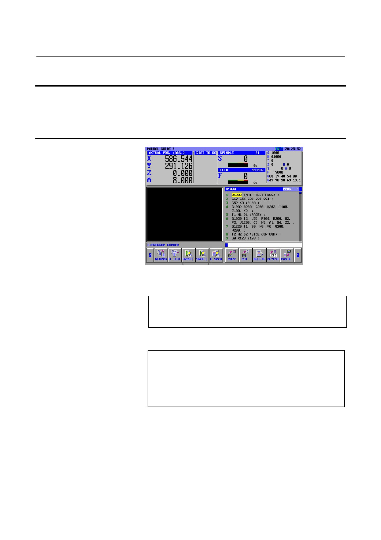
1.
In case of creating a new part program directly
Select EDIT mode by using a mode-selecting switch on a machine-operating panel
[NEWPRG]
(CREATE NEW PROGRAM)
1234 [CREATE]
(NEW PROGRAM NO.)
2.
In case of creating a new part program on the program list
window
Select EDIT mode by using a mode-selecting switch on a machine-operating panel
[O-LIST]
(OPEN PROGRAM)
[NEW]
(CREATE NEW PROGRAM)
1234 [CREATE]
(NEW PROGRAM NO.)
Select the newly entered program by ↓
[OPEN]
- 719 -
3.MACHINING CENTER
EXAMPLE OF PROGRAMMING
B-63874EN/05
3.5.2
Operations of “START” Menu
By pushing [START] in the soft-key menu for milling, the window
“INSERT STARTING COMMAND FOR MILLING” with the
following tabs is displayed.
<START>
: Fixed form sentence menu used for the top of
part program or each machining process.
<COORD CONV> : Coordinate conversion menu, which is
necessary for the machine on the inclined
surface, this is not used in this section.
<BLANK>
: Blank form menu, which is necessary for
animation.
3.5.2.1
Entering blank form data
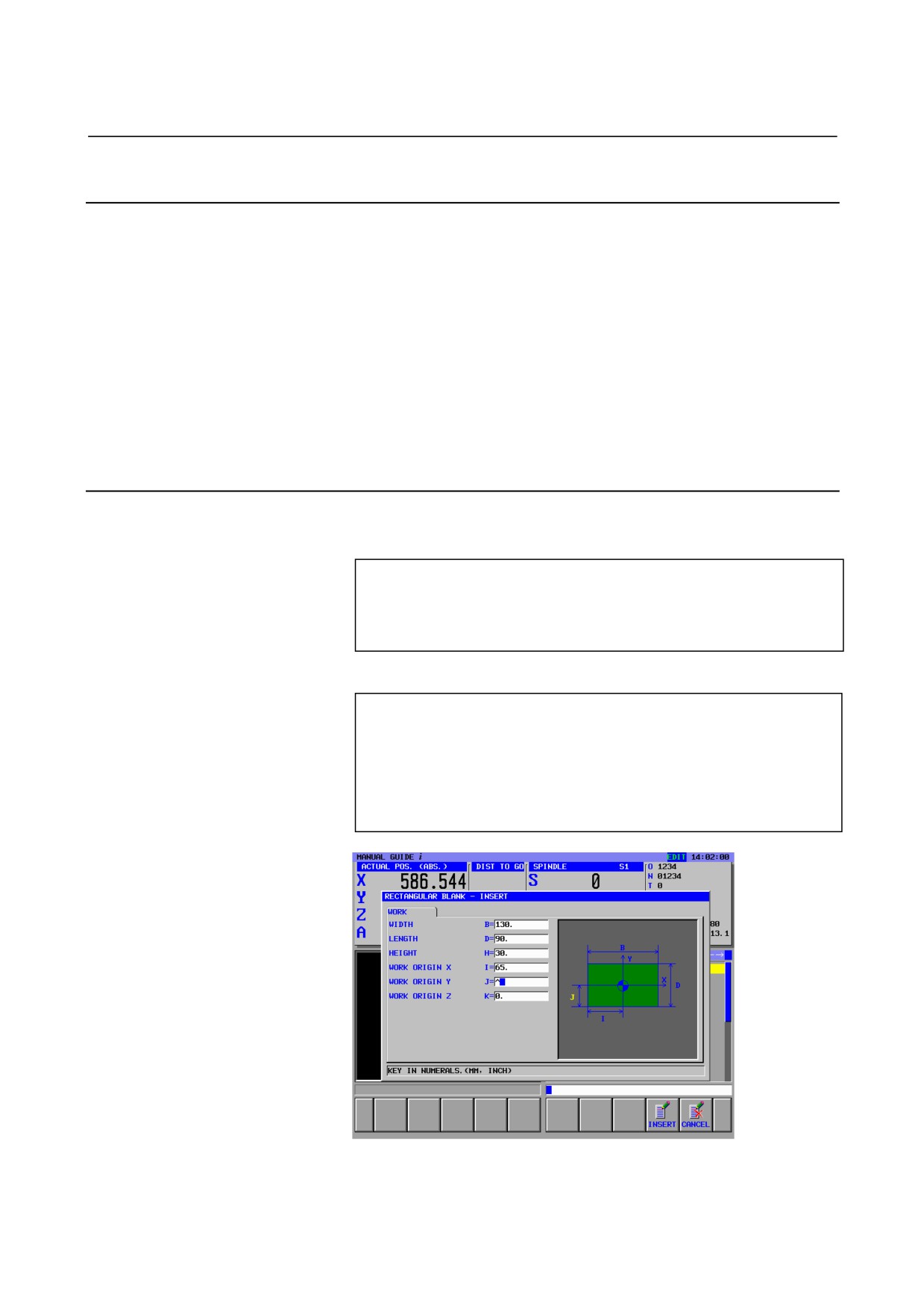
By selecting a tab <BLANK> by cursor key, blank form menu is
displayed.
(INSERT STARTING COMMAND FOR MILLING)
<BLANK>
↓
<<1. RECTANGULAR BLANK FIGURE>>
[SELECT]
Enter blank form data as a round bar.
(RECTANGULAR BLANK FIGURE - INSERT)
130 INPUT
(WIDTH)
90 INPUT
(LENGTH)
30 INPUT
(HEIGHT)
65 INPUT
(WORK ORIGIN X)
45 INPUT
(WORK ORIGIN Y)
0 INPUT
(WORK PROGIN Z)
[INSERT]
- 720 -

B-63874EN/05
EXAMPLE OF PROGRAMMING
3.MACHINING CENTER
3.5.3
Entering Tool Changing and Spindle Rotating Blocks for
Roughing Flat End Mill
3.5.3.1
Entering in ISO-code form directly
It is difficult to define the action of tool changing, spindle rotation,
approaching and releasing generally because there are many
difference depending on machine configuration. So, using ISO-code
form program can realize more flexible and safety part program.
G28 G91 Z0. ; INSERT
(Z-axis reference position return)
G28 G91 X0. Y0. ; INSERT
(X/Y-axis reference position return)
T01 M06 ; INSERT
(Tool change)
D1 ; INSERT
(Selecting tool data)
M03 S1000 ; INSERT
(Spindle rotation)
G00 G90 G54 X0. Y0. ; INSERT (X/Y-axis approaching)
G43 Z100. H1 ; INSERT
(Z-axis approaching)
3.5.3.2
Entering by fixed form sentence menu
ISO-code form part program can be entered from the fixed form
sentence menu. But, in such a case, proper fixed form sentence must
be prepared in advance.
(Soft-key group for milling cycle menu)
[START]
(INSERT STARTING COMMAND FOR MILLING)
<START>
↓
<<3.MILLING START>>
[INSERT]
NOTE
There may be a case that undefined value is
entered by “?” in the fixed form sentence menu, so
in this case, you need to replace the “?” by proper
value can be used in actual machining.
Place the cursor to the address with “?”, enter
numeric data, then push “ALTER”.
After altering the data, return the cursor to the EOB
at the end of the program.
- 721 -
3.MACHINING CENTER
EXAMPLE OF PROGRAMMING
B-63874EN/05
3.5.4
Entering Outer Wall Contouring Process
3.5.4.1
Entering outer wall contouring (rough) cycle block
Enter the 1st process : outer wall contouring process by the roughing
flat endmill (T01).
Enter machining type, cutting condition and so on.
(Soft-key menu for milling cycle menu)
[CYCLE]
(INSERT MILLING CYCLE)
→
<CONTOURING>
↓
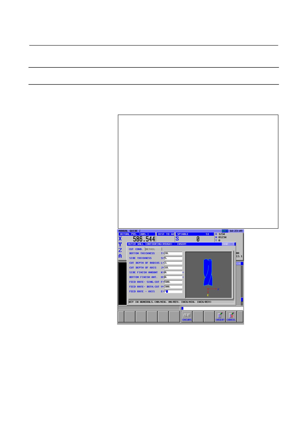
<<1.OUTER WALL CONTOURING(ROUGH)>>
[SELECT]
(OUTER WALL CONTOURING(ROUGH) - INSERT)
<CUT COND.>
20 INPUT
(BOTTOM THICKNESS)
5 INPUT
(SIDE THICKNESS)
3 INPUT
(CUT DEPTH OF RADIUS)
10 INPUT
(CUT DEPTH OF AXIS)
0 INPUT
(SIDE FINISH AMOUNT)
0 INPUT
(BOTTOM FINISH AMOUNT)
500 INPUT
(FEED RATE - SING.CUT)
300 INPUT
(FEED RATE - BOTH CUT)
200 INPUT
(FEED RATE - AXIS)
[INSERT]
- 722 -
B-63874EN/05
EXAMPLE OF PROGRAMMING
3.MACHINING CENTER
NOTE
1 In the cycle machining data menu window, all data
excepting cutting condition data are set
automatically. However, the data entered at
previously entered cycle of same kind are copied,
so you must enter the data if you have not entered
the same kind of cycle.
2 In the cycle machining data menu window, 2 tabs,
<CUT COND.> and <DETAIL>, are displayed.
In the <CUT COND.>, all data must be set. In the
<DETAIL>, all data are automatically set, so check
those data and modify them if necessary only
3.5.4.2
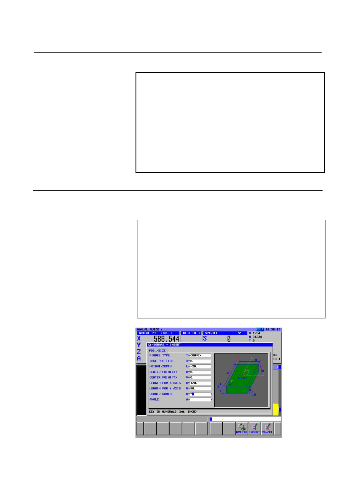
Entering figure for outer wall contouring (rough)
By inserting the cycle machining block, the window of contouring
figure menu is displayed, so select the XY-SQUARE CONVEX
(INSERT MILLING FIGURE)
<CONT. FIG.>
<<1.XY-SQUARE CONVEX>>
[SELECT]
(XY-SQUARE - INSERT)
<POS./SIZE>
[CONVEX]
(FIGURE TYPE)
0 INPUT
(BASE POSITION)
-20 INPUT
(HEIGHT/DEPTH)
0 INPUT
(CENTER POINT (X))
0 INPUT
(CENTER POINT (Y))
120 INPUT
(LENGTH FOR X AXIS)
80 INPUT
(LENGTH FOR Y AXIS)
[INSERT]
- 723 -
3.MACHINING CENTER
EXAMPLE OF PROGRAMMING
B-63874EN/05
3.5.5
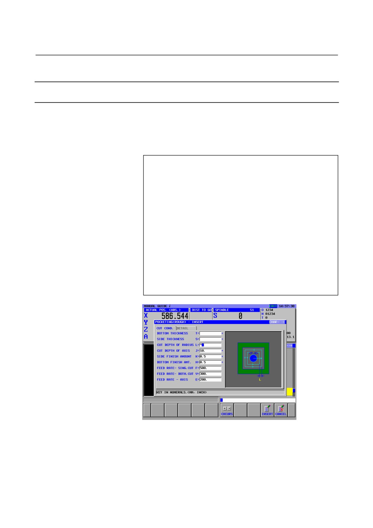
Entering Pocket Roughing Process
3.5.5.1
Entering pocket roughing cycle block
Enter the 2nd process : pocket roughing by a roughing flat endmill
(T01).
Since same tool with the 1st process is used, tool changing blocks are
not necessary.
Enter machining type, cutting condition and so on.
(Soft-key group for Milling cycle menu)
[CYCLE]
(INSERT MILLING CYCLE)
→
<POCKETING>
↓
<<1.POCKETING(ROUGH)>>
[SELECT]
(POCKETING(ROUGH) - INSERT)
<CUT COND.>
INPUT
(BOTTOM THICKNESS)
INPUT
(SIDE THICKNESS)
3 INPUT
(CUT DEPTH OF RADIUS)
10 INPUT
(CUT DEPTH OF AXIS)
0.5 INPUT
(SIDE FINISH AMOUNT)
0.5 INPUT
(BOTTOM FINISH AMOUNT)
500 INPUT
(FEED RATE - SING.CUT)
300 INPUT
(FED RATE - BOTH CUT)
200 INPUT
(FEED RATE - AXIS)
[INSERT]
- 724 -
B-63874EN/05
EXAMPLE OF PROGRAMMING
3.MACHINING CENTER
NOTE
1 In the cycle machining data menu window, all data
excepting cutting condition data are set
automatically. However, the data entered at
previously entered cycle of same kind are copied,
so you must enter the data if you have not entered
the same kind of cycle.
2 In the cycle machining data menu window, 2 tabs,
<CUT COND.> and <DETAIL>, are displayed.
In the <CUT COND.>, all data must be set. In the
<DETAIL>, all data are automatically set, so check
those data and modify them if necessary only
- 725 -
3.MACHINING CENTER
EXAMPLE OF PROGRAMMING
B-63874EN/05
3.5.5.2
Entering figure for pocket roughing
By inserting the cycle machining block, the window of
pocketing
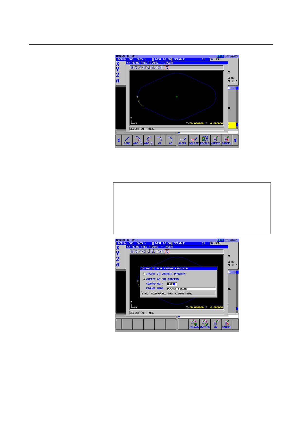
figure menu, so select the XY-FREE CONCAVE FIGURE.
(INSERT MILLING FIGURE)
<POCKET FIG>
↓
<<4.XY-FREE CONCAVE FIGURE>>
[SELECT]
(XY PLANE FREE FIGURE - INSERT)
(START POINT - INSERT)
INPUT
(FIGURE TYPE)
-50 INPUT
(START POINT X)
0 INPUT
(START POINT Y)
0 INPUT
(BASE POSITION)
-10 INPUT
(HEIGHT/DEPTH)
[OK]
[ARC
]
(ARC (CW) - INSERT)
INPUT
(END POINT X)
INPUT
(END POINT Y)
INPUT
(RADIUS)
-35 INPUT
(CENTER POINT CX)
0 INPUT
(CENTER POINT CY)
INPUT
(LAST CONNECTION)
[TANGNT]
(NEXT CONNECTION)
[OK]
[LINE]
(LINE - INSERT)
[R-UP]
(LINE DIRECTION)
INPUT
(END POINT X)
INPUT
(END POINT Y)
INPUT
(ANGLE)
[TANGNT]
(NEXT CONNECTION)
[OK]
[ARC
]
(ARC (CW) - INSERT)
INPUT
(END POINT X)
INPUT
(END POINT Y)
30 INPUT
(RADIUS)
0 INPUT
(CENTER POINT CX)
0 INPUT
(CENTER POINT CY)
[TANGNT]
(NEXT CONNECTION)
[OK]
[LINE]
(LINE - INSERT)
[R-DOWN]
(KINE DIRECTION)
INPUT
(END POINT X)
INPUT
(END POINT Y)
INPUT
(ANGLE)
[TANGNT]
(NEXT CONNECTION)
[OK]
- 726 -
B-63874EN/05
EXAMPLE OF PROGRAMMING
3.MACHINING CENTER
[ARC
]
(ARC (CW) - INSERT)
INPUT
(END POINT X)
INPUT
(END POINT Y)
15 INPUT
(RADIUS)
35 INPUT
(CENTER POINT CX)
0 INPUT
(CENTER POINT CY)
[TANGNT]
(NEXT CONNECTION)
[OK]
[LINE]
(LINE - INSERT)
[L-DOWN]
(LINE DIRECTION)
INPUT
(END POINT X)
INPUT
(END POINT Y)
INPUT
(ANGLE)
[TANGNT]
(NEXT CONNECTION)
[OK]
[ARC
]
(ARC (CW) - INSERT)
INPUT
(END POINT X)
INPUT
(END POINT Y)
30 INPUT
(RADIUS)
0 INPUT
(CENTER POINT CX)
0 INPUT
(CENTER POINT CY)
[TANGNT]
(NEXT CONNECTION)
[OK]
[LINBE]
(LINE - INSERT)
[L-UP]
(LINE DIRECTION)
INPUT
(END POINT X)
INPUT
(END POINT Y)
INPUT
(ANGLE)
[TANGNT]
(NEXT CONNECTION)
[OK]
[ARC
]
(ARC (CW) - INSERT)
-50 INPUT
(END POINT X)
0 INPUT
(END POINT Y)
15 INPUT
(RADIUS)
-35 INPUT
(CENTER POINT CX)
0 INPUT
(CENTER POINT CY)
INPUT
(NEXT CONNECTION)
[OK]
- 727 -
3.MACHINING CENTER
EXAMPLE OF PROGRAMMING
B-63874EN/05
Figure blocks can be registered into the current part program directly,
and also can be registered as another sub program.
Registered figure blocks can be used also for finishing, so in this
example, register them as a sub program.
(XY PLANE FREE FIGURE - INSERT)
[CREATE]
(METHOD OF FREE FIGURE CREATION)
↓
<CREATE AS SUB PROGRAM>
8200 INPUT
(SUBPRO NO.)
POCKET FIGURE
(FIGURE NAME)
[ISLAND]
- 728 -
B-63874EN/05
EXAMPLE OF PROGRAMMING
3.MACHINING CENTER
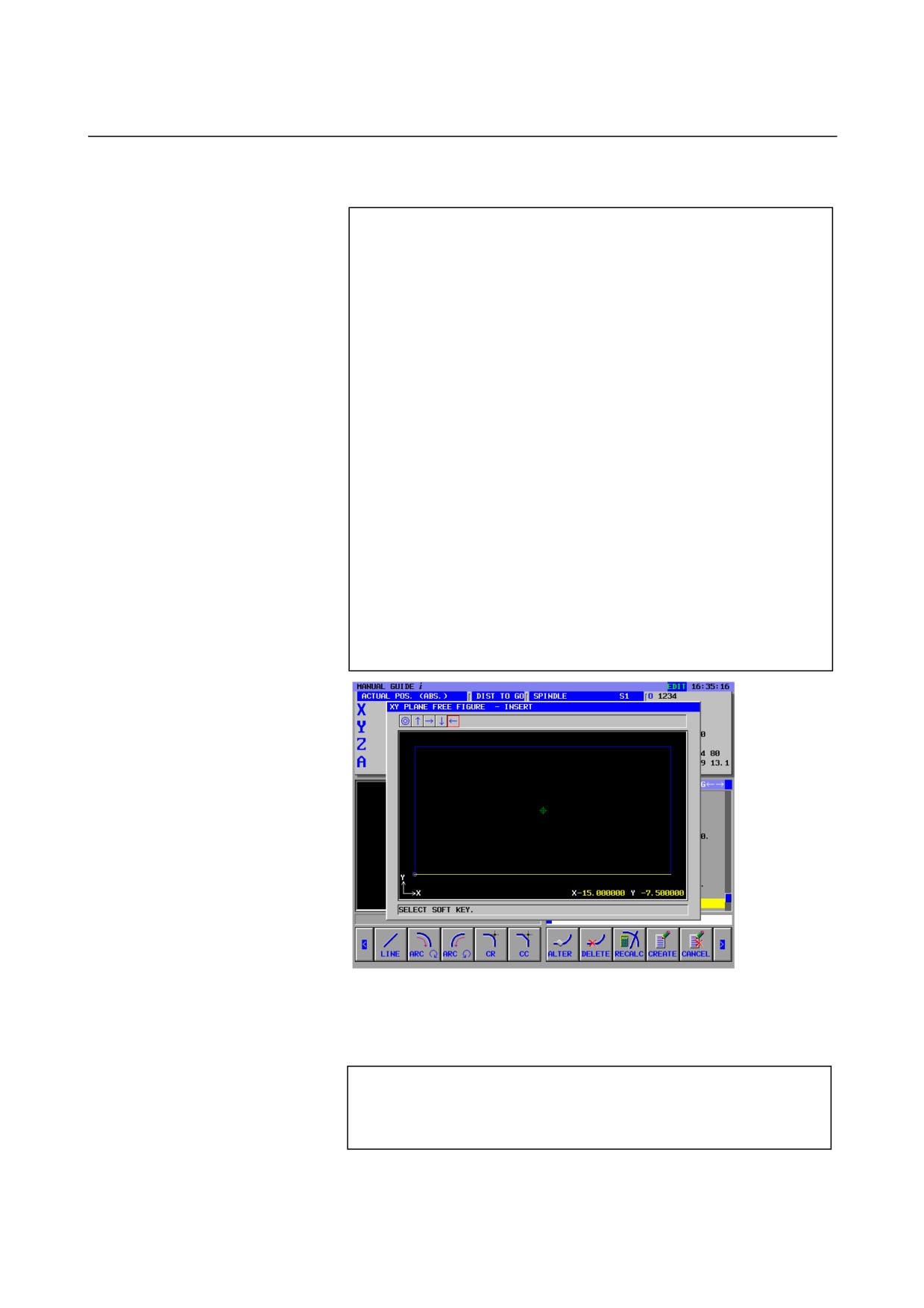
There is an island in a pocket, so enter island figure continuously.
(START POINT - INSERT)
INPUT
(FIGURE TYPE)
-15 INPUT
(START POINT X)
-7.5 INPUT
(START POINT Y)
0 INPUT
(BASE POSITION)
-10 INPUT
(HEIGHT / DEPTH)
[OK]
[LINE]
(LINE - INSERT)
[UP]
(LINE DIRETION)
7.5 INPUT
(END POINT Y)
[OK]
[LINE]
(LINE - INSERT)
[RIGHT]
(LINE DIRECTION)
15 INPUT
(END POINT X)
[OK]
[LINE]
(LINE - INSERT)
[DOWN]
(LINE DIRECTION)
-7.5 INPUT
(END POINT Y)
[OK]
[LINE]
(LINE - INSERT)
[LEFT]
(LINE DIRECTION)
-15 INPUT
(END POINT X)
[OK]
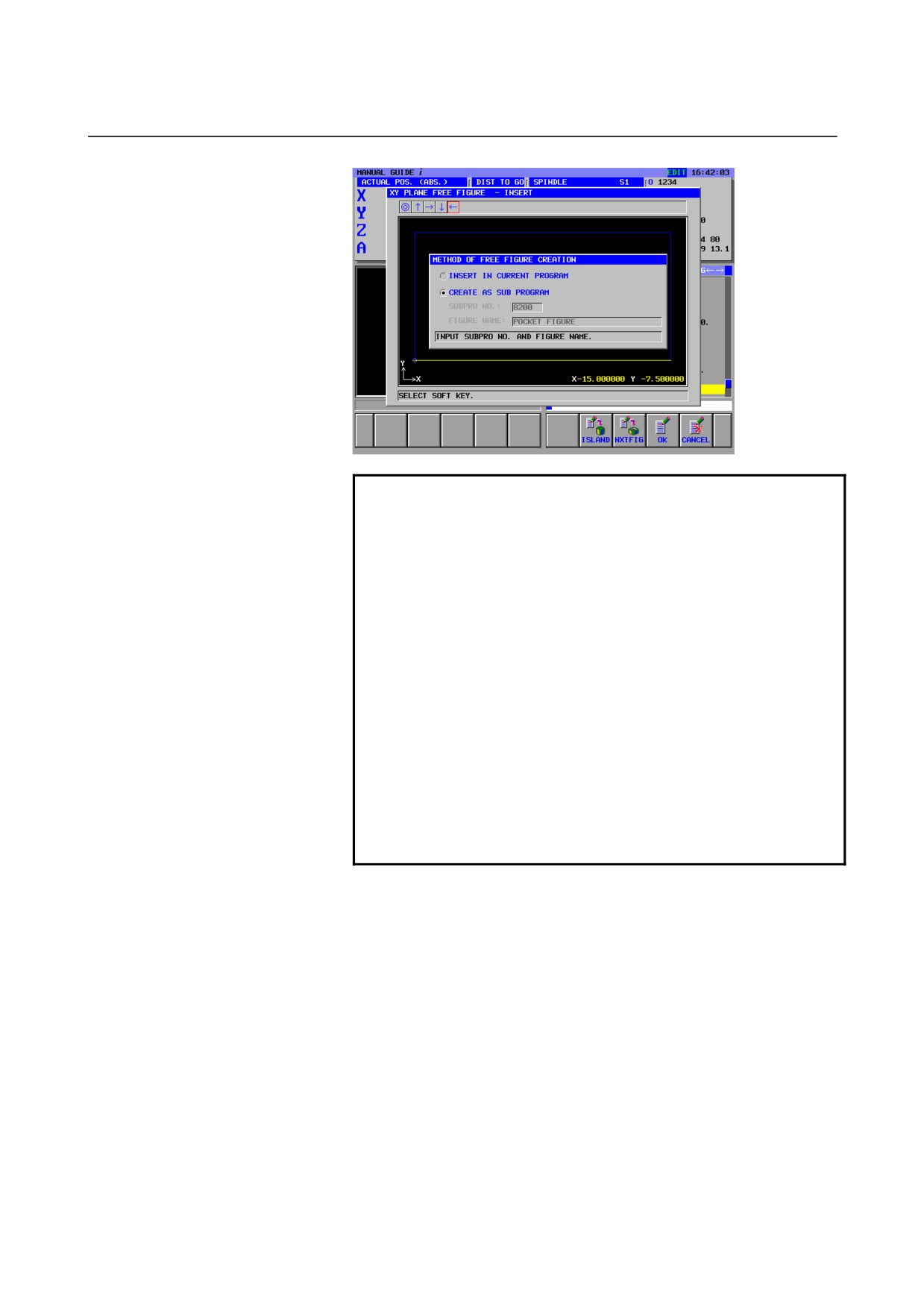
Entered figure blocks were already defined to make as a subprogram,
so check the contents of them and create it as a subprogram by
pressing [OK]
(XY PLANE FREE FIGURE - INSERT)
[CREATE]
(METHOD OF FREE FIGURE CREATION)
[OK]
- 729 -
3.MACHINING CENTER
EXAMPLE OF PROGRAMMING
B-63874EN/05
NOTE
Registered sub program can be displayed in a figure
menu tab, “SUBPROGRAM”.
In this case, set the parameters No14720 to 14723 in
advance.
For this example, set those parameters as follow.
No.14720=8000 (Minimum program number of sub
programs displayed in the turning
machining sub program menu)
No.14721=8499 (Maximum program number of sub
programs displayed in the turning
machining sub program menu)
No.14722=8500 (Minimum program number of sub
programs displayed in the milling
machining sub program menu)
No.14723=8999 (Maximum program number of sub
programs displayed in the milling
machining sub program menu)
- 730 -

B-63874EN/05
EXAMPLE OF PROGRAMMING
3.MACHINING CENTER
3.5.6
Entering Tool Changing and Spindle Rotating Blocks for
Finishing Flat End Mill
3.5.6.1
Entering in ISO-code form directly
For pocket finishing, enter commands for operations including
changing tools, specifying the spindle, and approaching the machining
start point.
G28 G91 Z0. ; INSERT
(Z-axis reference position return)
G28 G91 X0. Y0. ; INSERT
(X/Y-axis reference position return)
T02 M06 ; INSERT
(Tool change)
D2 ; INSERT
(Selecting tool data)
M03 S1500 ; INSERT
(Spindle rotation)
G00 G90 G54 X0. Y0. ; INSERT (X/Y-axis approaching)
G43 Z100. H2 ; INSERT
(Z-axis approaching)
3.5.6.2
Entering by fixed form sentence menu
ISO-code form part program can be entered from the fixed form
sentence menu. The already prepared fixed form sentence as
3.MILLING START was made with entering undefined data as “?”,
so it can be used also for finishing.
(Soft-key group for milling cycle menu)
[START]
(INSERT STARTING COMMAND FOR MILLING)
<START>
↓
<<3.MILLING START>>
[INSERT]
NOTE
There may be a case that undefined value is
entered by “?” in the fixed form sentence menu, so
in this case, you need to replace the “?” by proper
value can be used in actual machining.
Place the cursor to the address with “?”, enter
numeric data, then push “ALTER”.
After altering the data, return the cursor to the EOB
at the end of the program.
- 731 -