FANUC MANUAL GUIDE i. OPERATOR’S MANUAL - page 8
9.MACHINING SIMULATION AND DRAWING DURING MACHINING OPERATION
B-63874EN/05
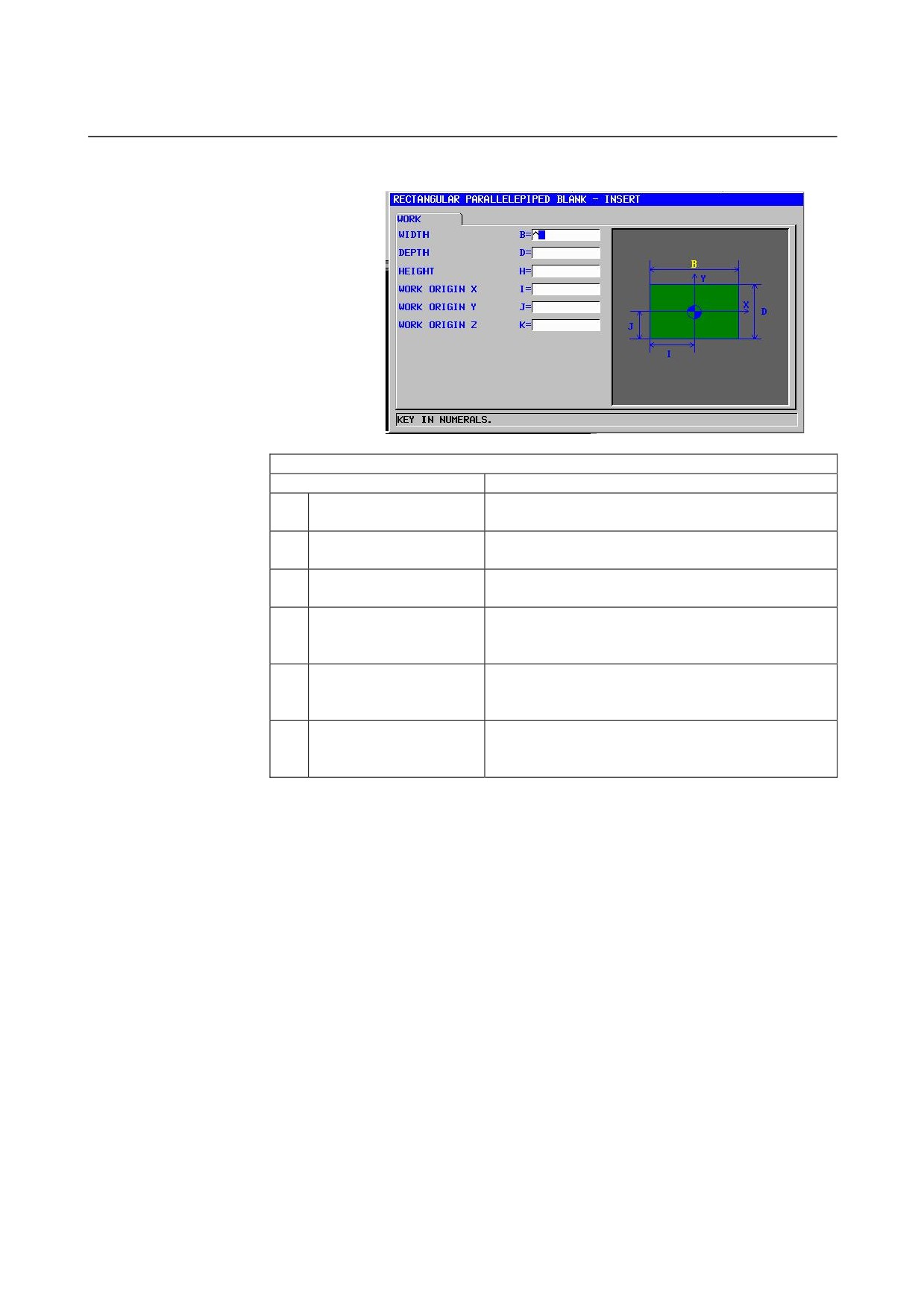
Blank form block (rectangular solid): G1902
WORK
Data item
Meaning
B
WIDTH
Width of the rectangular solid blank. Length in the
X-axis direction (positive value)
D
DEPTH
Depth of the rectangular solid blank. Length in the
Y-axis direction (positive value)
H
HEIGHT
Height of the rectangular solid blank. Length in the
Z-axis direction (positive value)
I
WORK ORIGIN X
Distance in the X-axis direction from the lower left
corner of the rectangular solid to workpiece origin
(positive or negative value)
J
WORK ORIGIN Y
Distance in the Y-axis direction from the lower left
corner of the rectangular solid to workpiece origin
(positive or negative value)
K
WORK ORIGIN Z
Distance in the Z-axis direction from the lower left
corner of the rectangular solid to workpiece origin
(positive or negative value)
- 192 -
B-63874EN/05
OPERATION
9.MACHINING SIMULATION AND DRAWING DURING MACHINING
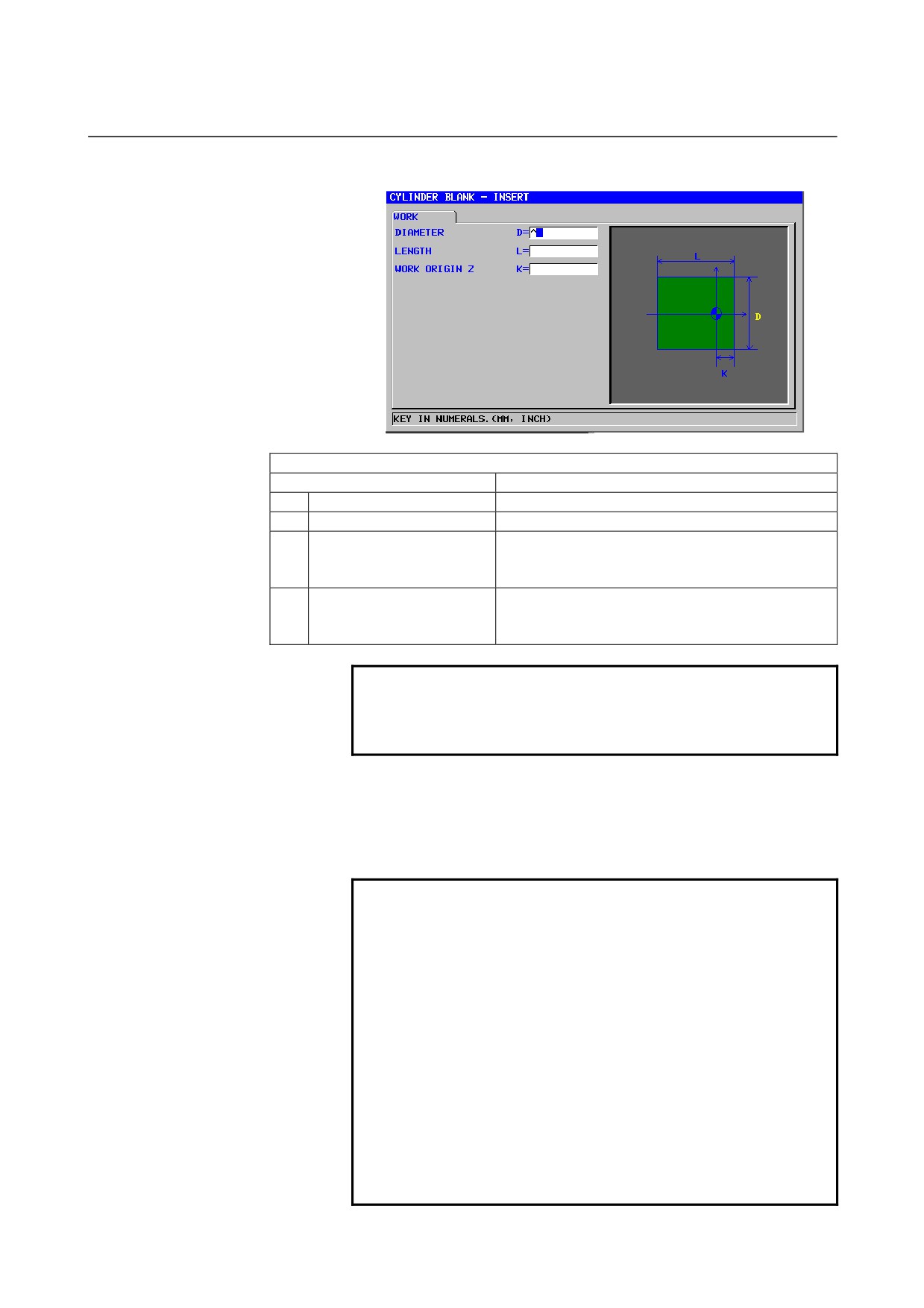
Blank form block (column): G1900
WORK
Data item
Meaning
D
DIAMETER
Diameter of the column blank (positive value)
L
LENGTH
Length of the column blank (positive value)
K
WORK ORIGIN Z
Cutting allowance of the end face of the blank
(Z-axis distance between the end face and
workpiece origin) (positive value)
W
WORK ORIGIN Z (SPN 2)
Cutting allowance of the back end face of the blank
(Z-axis distance between the back end face and
workpiece origin) (positive value)
NOTE
The input item of “WORK ORIGIN Z(SPN 2) (W)“ is
prepared for a machine with a subspindle, and is
displayed when the parameter No.14702 #1 = 1.
Blank form block (column(around X)): G1906
This blank is used for the machining simulation whose workpiece
rotates around X-axis in machining centers.
Data setting is the same as the above column.
NOTE
1 There is the following limitations when the simulation
whose workpiece rotates around X axis is executed.
• This function is available in only machining
centers.
• Turning cycle can’t be simulated.
• Polar coordinate interpolation can’t be
simulated.
• Under simulation as workpiece rotates
workpiece around X-axis, coordinate is
displayed in X, Y, -Z.
2 The following parameter setting is necessary.
• No.27003#2=1, 27003#1=0 and 27003#0=0
• No.14717 : The axis number of work rotation
axis
- 193 -
9.MACHINING SIMULATION AND DRAWING DURING MACHINING OPERATION
B-63874EN/05
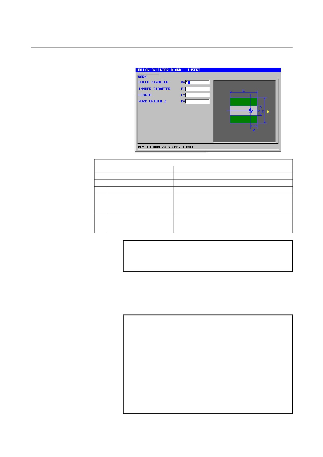
Blank form block (column with a hole): G1901
WORK
Data item
Meaning
D
DIAMETER
Diameter of the column blank (positive value)
E
INNER DIAMETER
Inner diameter of the column blank (positive value)
L
LENGTH
Length of the column blank (positive value)
K
WORK ORIGIN Z
Cutting allowance of the end face of the blank
(Z-axis distance between the end face and
workpiece origin) (positive value)
W
WORK ORIGIN Z (SPN 2)
Cutting allowance of the back end face of the blank
(Z-axis distance between the back end face and
workpiece origin) (positive value)
NOTE
The input item of “WORK ORIGIN Z (SPN 2) (W)”
is prepared for a machine with a subspindle, and is
displayed when the parameter No.14702#1 = 1.
Blank form block (column with a hole (around X)): G1907
This blank is used for the machining simulation whose workpiece
rotates around X-axis in machining centers.
Data setting is the same as the above column with a hole.
NOTE
1 There is the following limitations when the
simulation whose workpiece rotates around X axis
is executed.
- This function is available in only machining
centers.
- Turning cycle can’t be simulated.
- Polar coordinate interpolation can’t be simulated.
- Under simulation as workpiece rotates workpiece
around X-axis, coordinate is displayed in X, Y, -Z.
2 The following parameter setting is necessary.
- No.27003#2=1, 27003#1=0 and 27003#0=0
- No.14717 : The axis number of work rotation axis
- 194 -
B-63874EN/05
OPERATION
9.MACHINING SIMULATION AND DRAWING DURING MACHINING
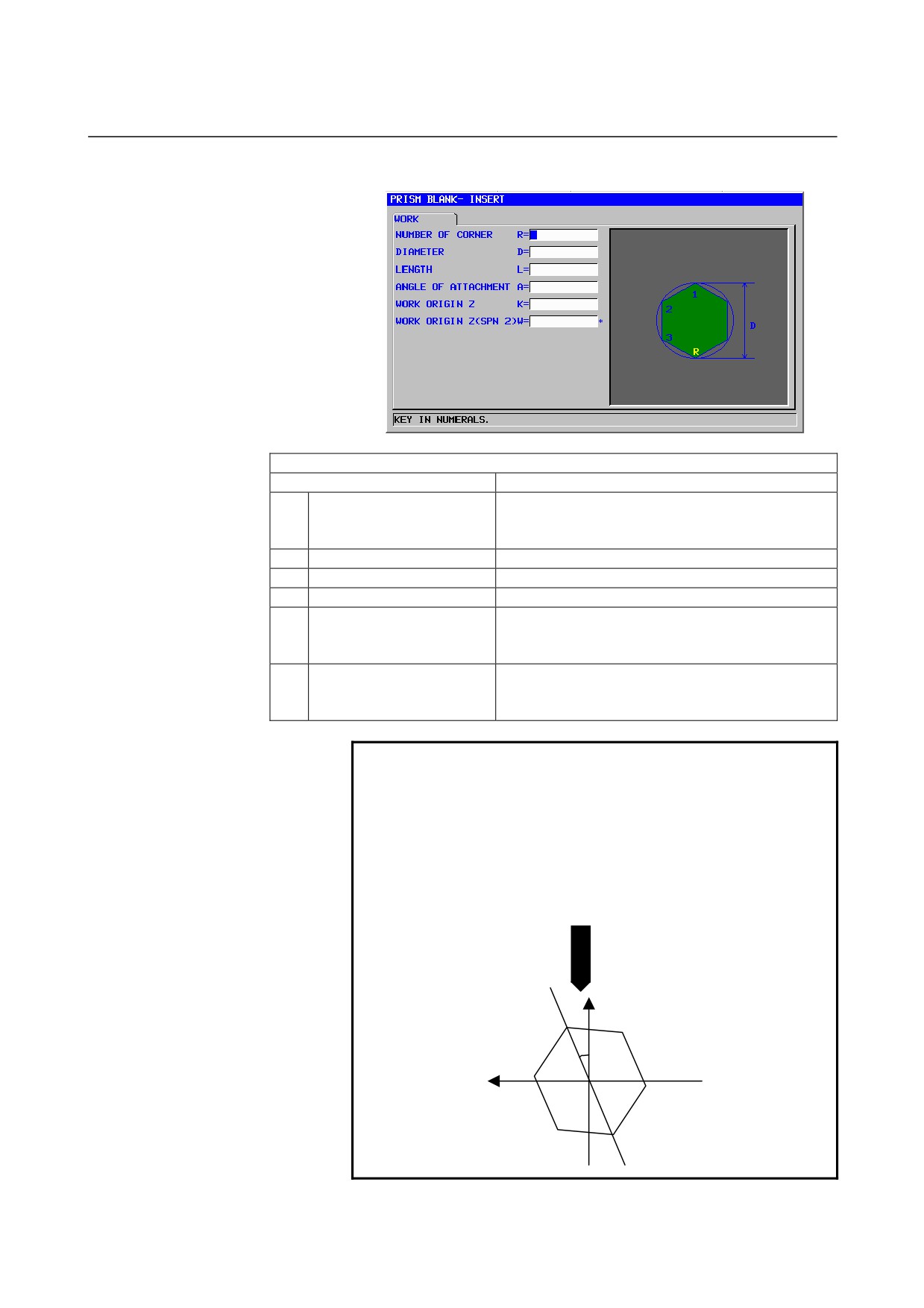
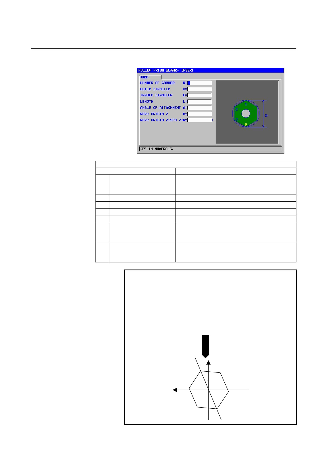
Blank form block (prism): G1903
WORK
Data item
Meaning
R
NUMBER OF CORNER
The number of corner
This must be a integer, larger than 2 and smaller
than 100.
D
DIAMETER
Diameter of the prism blank (positive value)
L
LENGTH
Length of the prism blank (positive value)
A
Angle of attachment
The angle between a corner and X axis
K
WORK ORIGIN Z
Cutting allowance of the end face of the blank
(Z-axis distance between the end face and
workpiece origin) (positive value)
W
WORK ORIGIN Z (SPN 2)
Cutting allowance of the back end face of the blank
(Z-axis distance between the back end face and
workpiece origin) (positive value)
NOTE
1 The input item of “WORK ORIGIN Z(SPN 2) (W)“ is
prepared for a machine with a subspindle, and is
displayed when the parameter No.14702 #1 = 1.
2 Only equilateral prism can be displayed.
3 Angle of attachment is the angle that is formed by
X-axis and one comer of blank figure.( Refer to the
following figure. )
X
A
Y
- 195 -
9.MACHINING SIMULATION AND DRAWING DURING MACHINING OPERATION
B-63874EN/05
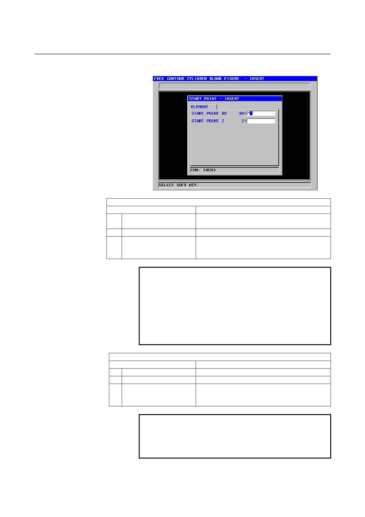
Blank form block (column with a hole): G1904
WORK
Data item
Meaning
R
NUMBER OF CORNER
The number of corner
This must be a integer, larger than 2 and smaller
than 100.
D
DIAMETER
Diameter of the prism blank (positive value)
E
INNER DIAMETER
Inner diameter of the prism blank (positive value)
L
LENGTH
Length of the prism blank (positive value)
A
Angle of attachment
The angle between a corner and X axis
K
WORK ORIGIN Z
Cutting allowance of the end face of the blank
(Z-axis distance between the end face and
workpiece origin) (positive value)
W
WORK ORIGIN Z (SPN 2)
Cutting allowance of the back end face of the blank
(Z-axis distance between the back end face and
workpiece origin) (positive value)
NOTE
1 The input item of “WORK ORIGIN Z(SPN 2) (W)“ is
prepared for a machine with a subspindle, and is
displayed when the parameter No.14702 #1 = 1.
2 Only equilateral prism can be displayed.
3 Angle of attachment is the angle that is formed by
X-axis and one comer of blank figure.( Refer to the
following figure. )
X
A
Y
- 196 -
B-63874EN/05
OPERATION
9.MACHINING SIMULATION AND DRAWING DURING MACHINING
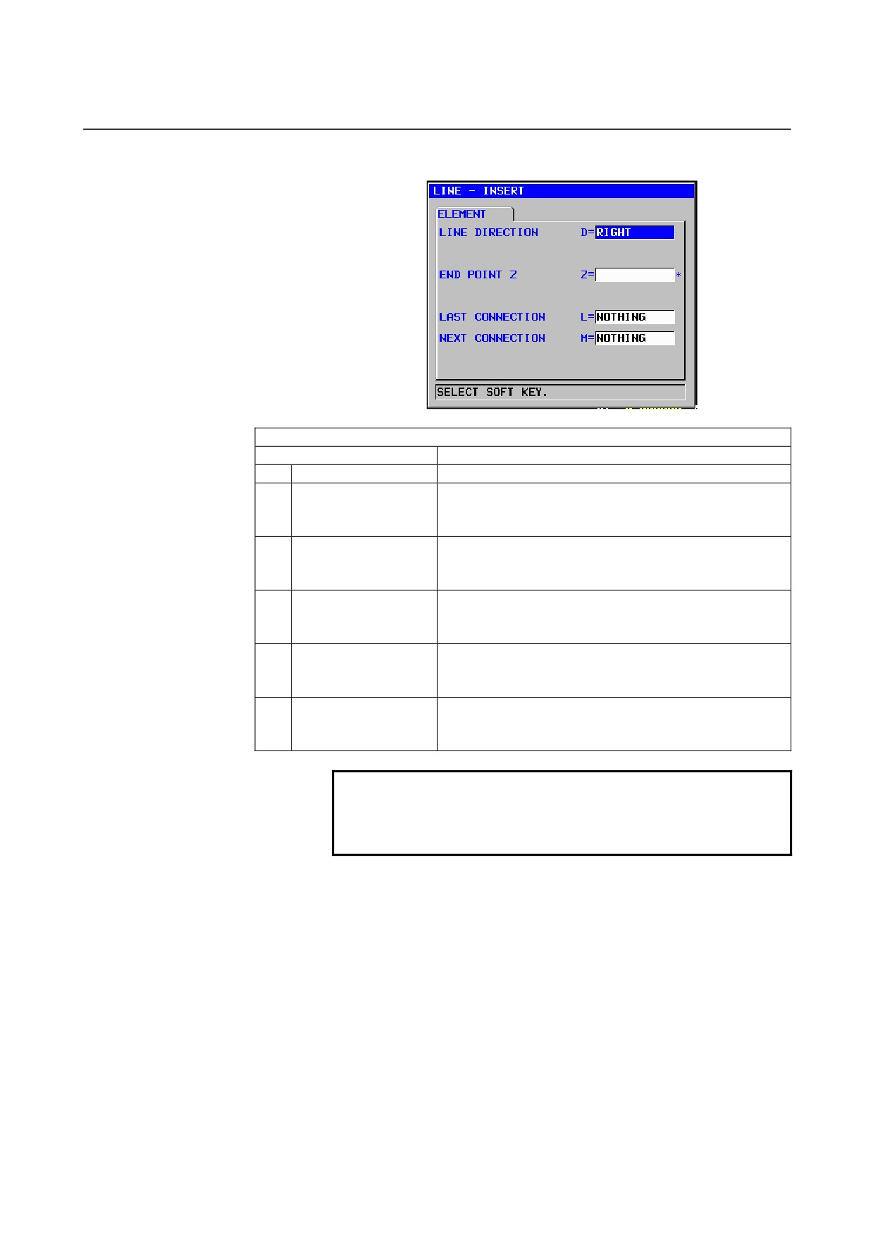
Arbitrary blank figure block (start point): G1970
ELEMENT
(INPUT DATA)
(Note 1, 2)
Data item
Meaning
DX
START POINT DX
X coordinate of the start point of an arbitrary figure
(positive value)
Z
START POINT Z
Z coordinate of the start point of an arbitrary figure
W
WORK ORIGIN Z (SPN 2)
Cutting allowance of a blank rear end face (distance
between the rear end face and workpiece origin in
the Z-axis direction) (positive value) (Note 3)
NOTE
1
‘INPUT DATA’ means the items, which are
displayed on the input data window in editing or
altering.
2 Figure input is performed based on the +X-side
cross section of the ZX plane of a round rod.
3 The input item of “WORK ORIGIN Z (SPN 2) (W)”
is prepared for a machine with a subspindle, and is
displayed when the parameter No.14702 #1 = 1.
ELEMENT
(OUTPUT DATA)
(Note 3)
Data item
Meaning
H
START POINT DX
X coordinate of the start point
(input value)
V
START POINT Z
Z coordinate of the start point
(input value)
W
WORK ORIGIN Z (SPN 2)
Cutting allowance of a blank rear end face (distance
between the rear end face and workpiece origin in
the Z-axis direction) (positive value) (input value)
NOTE
3
‘OUTPUT DATA’ means the items, which are
displayed on the program window as creating
program. It can be referenced only for program
display purposes.
- 197 -
9.MACHINING SIMULATION AND DRAWING DURING MACHINING OPERATION
B-63874EN/05
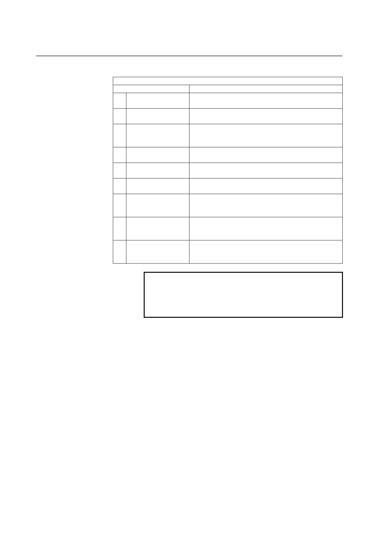
Arbitrary blank figure block (line): G1971
ELEMENT
(INPUT DATA)
(Note 1)
Data item
Meaning
D
LINE DIRECTION
Select a line direction from the displayed soft key menu.
DX
END POINT DX
X coordinate of a line end point
Remark) This item may not be displayed, depending on
the input line direction value.
Z
END POINT Z
Z coordinate of a line end point
Remark) This item may not be displayed, depending on
the input line direction value.
A
ANGLE
Line angle
Remark) This item may not be displayed, depending on
the input line direction value.
L
LAST CONNECTION
[TANGNT] : Contacts the immediately preceding figure.
[NOTHING] : Does not contact the immediately preceding
figure. (initial value)
M
NEXT CONNECTION
[TANGNT] : Contacts the next figure.
[NOTHING] : Does not contact the next figure. (initial
value)
NOTE
1
‘INPUT DATA’ means the items, which are
displayed on the input data window in editing or
altering.
- 198 -
B-63874EN/05
OPERATION
9.MACHINING SIMULATION AND DRAWING DURING MACHINING
ELEMENT
(OUTPUT DATA)
(Note 2)
Data item
Meaning
H
END POINT X
X coordinate of the end point of a straight line
(calculation result)
V
END POINT Z
Z coordinate of the end point of a straight line
(calculation result)
K
LINE DIRECTION
The direction of a straight line is selected from a menu
indicated on a soft key.
(input value)
C*
END POINT DX
X coordinate of the end point of a straight line
(input value)
D*
END POINT Z
Z coordinate of the end point of a straight line
(input value)
A*
ANGLE
Straight-line angle
(input value)
L
LAST CONNECTION
[1] : In contact with the immediately preceding figure
[2] : Not in contact with the immediately preceding figure
(input value)
M
NEXT CONNECTION
[1] : In contact with the immediately following figure
[2] : Not in contact with the immediately following figure
(input value)
S
SELECT FIG. INFO.
In the case of plural intersection or contact, the operator
sets a candidate.
(input value)
NOTE
2
‘OUTPUT DATA’ means the items, which are
displayed on the program window as creating
program. It can be referenced only for program
display purposes.
- 199 -
9.MACHINING SIMULATION AND DRAWING DURING MACHINING OPERATION
B-63874EN/05
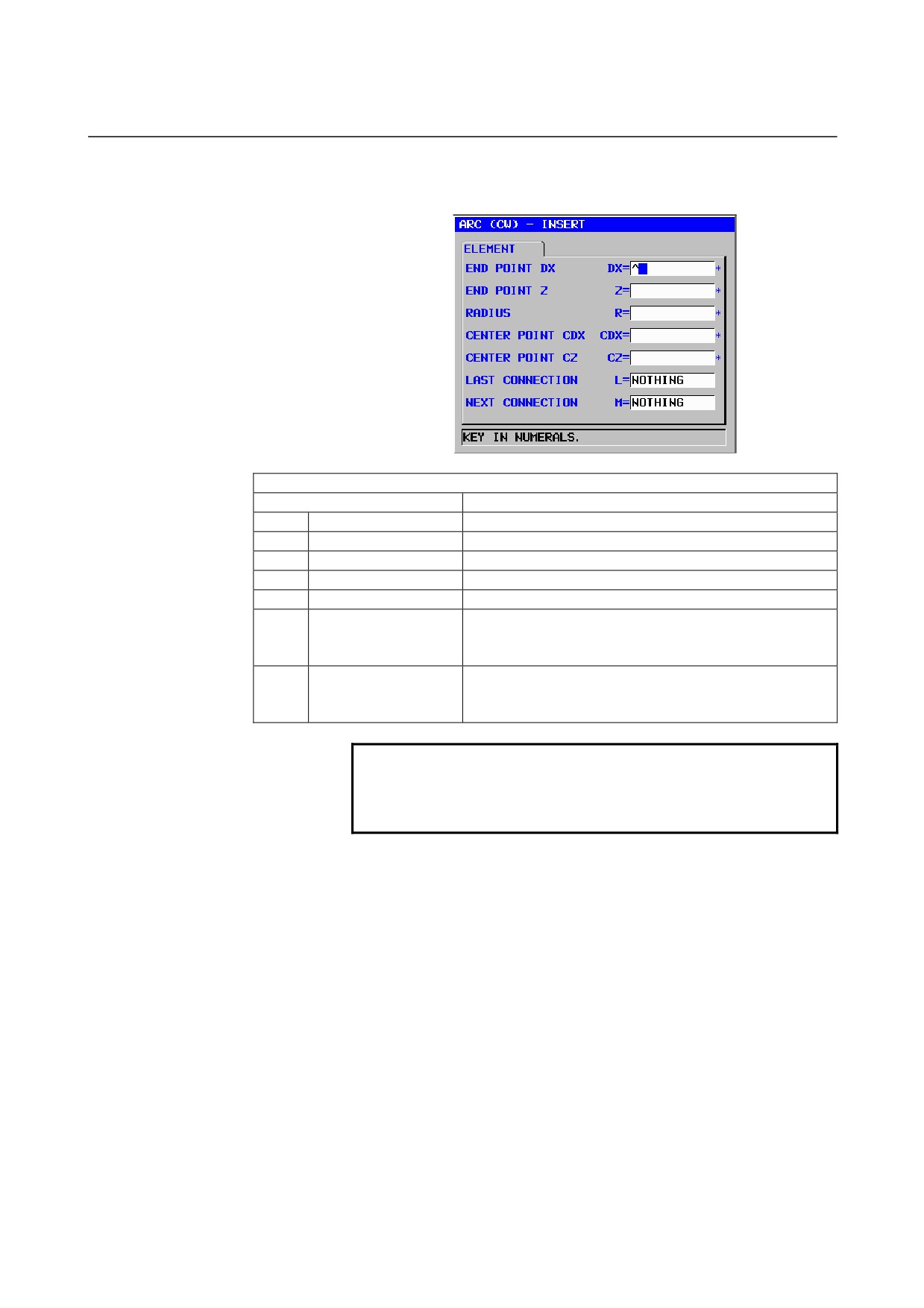
Arbitrary blank figure block (arc(CW)): G1972
Arbitrary blank figure block (arc(CCW)): G1973
ELEMENT
(INPUT DATA)
(Note 1)
Data item
Meaning
DX
END POINT DX
X coordinate of an arc end point
Z
END POINT Z
Z coordinate of an arc end point
R
RADIUS
Radius of an arc
CDX
CENTER POINT CDX
X coordinate of an arc center
CZ
CENTER POINT CZ
Z coordinate of an arc center
L
LAST CONNECTION
[TANGNT] : Contacts the immediately preceding figure.
[NOTHING] : Does not contact the immediately preceding
figure. (initial value)
M
NEXT CONNECTION
[TANGNT] : Contacts the next figure.
[NOTHING] : Does not contact the next figure. (initial
value)
NOTE
1
‘INPUT DATA’ means the items, which are
displayed on the input data window in editing or
altering.
- 200 -
B-63874EN/05
OPERATION
9.MACHINING SIMULATION AND DRAWING DURING MACHINING
ELEMENT
(OUTPUT DATA)
(Note 2)
Data item
Meaning
H
END POINT X
X coordinate of an arc end point (calculation result)
V
END POINT Z
Z coordinate of an arc end point (calculation result)
R
RADIUS
Arc radius
(calculation result)
I
CENTER POINT X
X coordinate of an arc center
(calculation result)
J
CENTER POINT Z
Z coordinate of an arc center
(calculation result)
C*
END POINT X
X coordinate of an arc end point
(input value)
D*
END POINT Z
Z coordinate of an arc end point
(input value)
E*
RADIUS
Arc radius
(input value)
P*
CENTER POINT CDX
X coordinate of an arc center
(input value)
Q*
CENTER POINT CZ
Z coordinate of an arc center
(input value)
L
LAST CONNECTION
[1] : In contact with the immediately preceding figure
[2] : Not in contact with the immediately preceding figure
(input value)
M
NEXT CONNECTION
[1] : In contact with the immediately preceding figure
[2] : Not in contact with the immediately preceding figure
(input value)
S
SELECT FIG. INFO.
In the case of plural intersection or contact, the operator
sets a candidate.
(input value)
NOTE
2
‘OUTPUT DATA’ means the items, which are
displayed on the program window as creating
program. It can be referenced only for program
display purposes.
- 201 -
9.MACHINING SIMULATION AND DRAWING DURING MACHINING OPERATION
B-63874EN/05
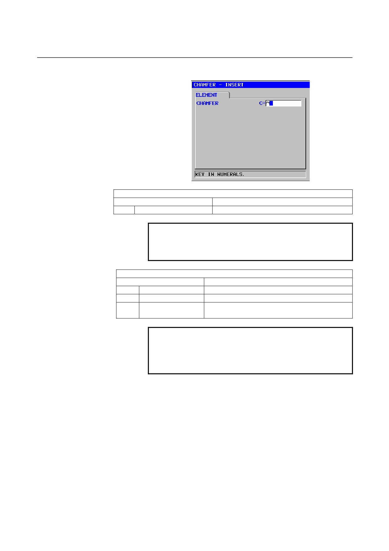
Arbitrary blank figure block (chamfering): G1974
ELEMENT
(INPUT DATA)
(Note 1)
Data item
Meaning
C
CHAMFER
Chamfer (radius value, positive value)
NOTE
1
‘INPUT DATA’ means the items, which are
displayed on the input data window in editing or
altering.
ELEMENT
(OUTPUT DATA)
(Note 2)
Data item
Meaning
H
END POINT X
X coordinate of an arc end point
(calculation result)
V
END POINT Z
Z coordinate of an arc end point
(calculation result)
C
CHAMFER
Amount of chamfering (radius value, positive value)
(input value)
NOTE
2
‘OUTPUT DATA’ means the items, which are
displayed on the program window as creating
program. It can be referenced only for program
display purposes.
- 202 -
B-63874EN/05
OPERATION
9.MACHINING SIMULATION AND DRAWING DURING MACHINING
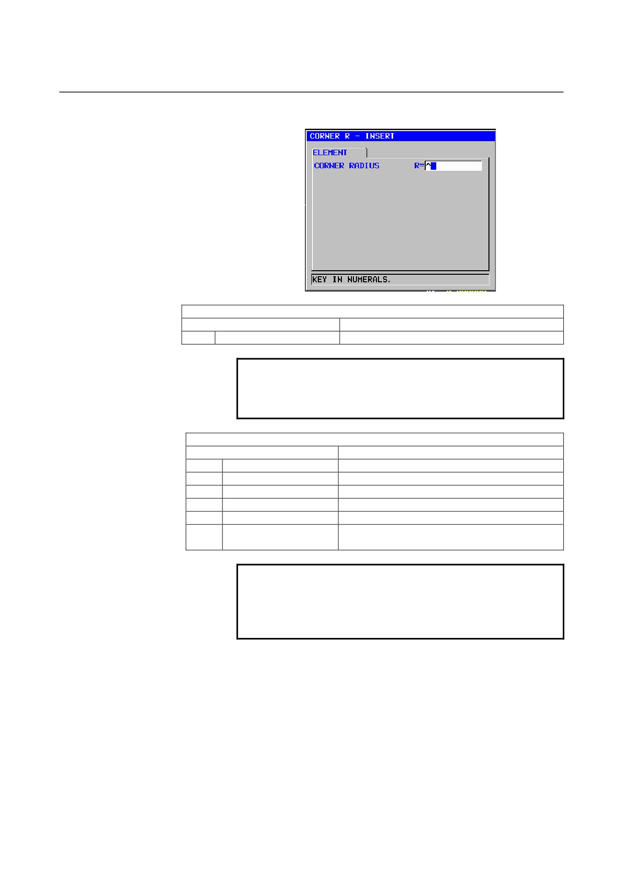
Arbitrary blank figure block (corner rounding): G1975
ELEMENT
(INPUT DATA)
(Note 1)
Data item
Meaning
R
CORNER RADIUS
Corner R radius (radius value, positive value)
NOTE
1
‘INPUT DATA’ means the items, which are
displayed on the input data window in editing or
altering.
ELEMENT
(OUTPUT DATA)
(Note 2)
Data item
Meaning
H
END POINT X
X coordinate of an arc end point (calculation result)
V
END POINT Z
Z coordinate of an arc end point (calculation result)
R
RADIUS
Arc radius
(calculation result)
I
CENTER POINT X
X coordinate of an arc center
(calculation result)
J
CENTER POINT Z
Z coordinate of an arc center
(calculation result)
K
ROTATION DIRECTION
[2] : clockwise
[3] : counterclockwise
NOTE
2
‘OUTPUT DATA’ means the items, which are
displayed on the program window as creating
program. It can be referenced only for program
display purposes.
Arbitrary blank figure block (end) : G1976
This block is output at the end of a series of arbitrary figure blocks.
- 203 -
9.MACHINING SIMULATION AND DRAWING DURING MACHINING OPERATION
B-63874EN/05
Arbitrary blank figure block (around X) (start point): G1970
Arbitrary blank figure block (around X) (line): G1971
Arbitrary blank figure block (around X) (arc(CW)): G1972
Arbitrary blank figure block (around X) (arc(CCW)): G1973
Arbitrary blank figure block (around X) (chamfering): G1974
Arbitrary blank figure block (around X) (corner rounding): G1975
Arbitrary blank figure block (around X) (end) : G1976
This blank is used for the machining simulation whose workpiece
rotates around X-axis in machining centers.
Data setting is the same as the above arbitrary blank figure.
NOTE
1 There is the following limitations when the simulation
whose workpiece rotates around X axis is executed.
• This function is available in only machining
centers.
• Turning cycle can’t be simulated.
• Polar coordinate interpolation can’t be
simulated.
• Under simulation as workpiece rotates
workpiece around X-axis, coordinate is
displayed in X, Y, -Z.
2 The following parameter setting is necessary.
• No.27003#2=1, 27003#1=0 and 27003#0=0
• No.14717 : The axis number of work rotation
axis
- 204 -
B-63874EN/05
OPERATION
9.MACHINING SIMULATION AND DRAWING DURING MACHINING
NOTE
1 The arc commands (G1972 and G1973) and corner
rounding command (G1975) are changed to linear
elements with several blocks, and then displayed.
Depending on the figure, it may require a longer
time before being completely displayed.
2 Input the end point of an arbitrary blank figure such
that it matches with the start point.
3 A series of arbitrary figures must be enclosed with
G1970 (start point) and G1976 (arbitrary figure
end).
4 To edit an arbitrary figure, place the cursor on the
block of G1970 (start point), then press [ALTER].
5 A figure for an end face portion cannot be
specified. An end face portion must contain vertical
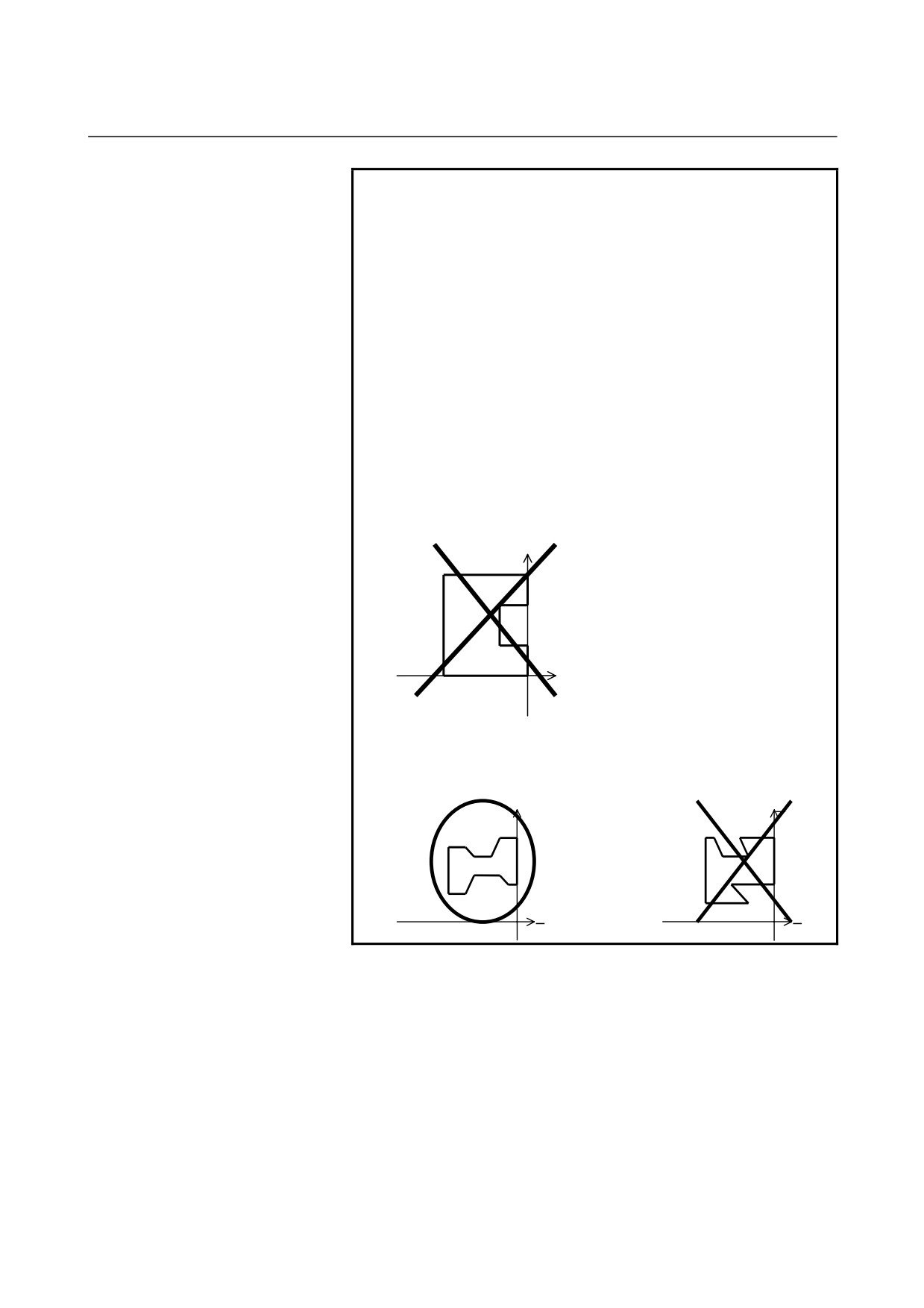
lines only.
X
Z
6 A figure in the Z direction from an end face portion
must be a monotonously increasing or decreasing
figure.
X
X
Z
Z
- 205 -
9.MACHINING SIMULATION AND DRAWING DURING MACHINING OPERATION
B-63874EN/05
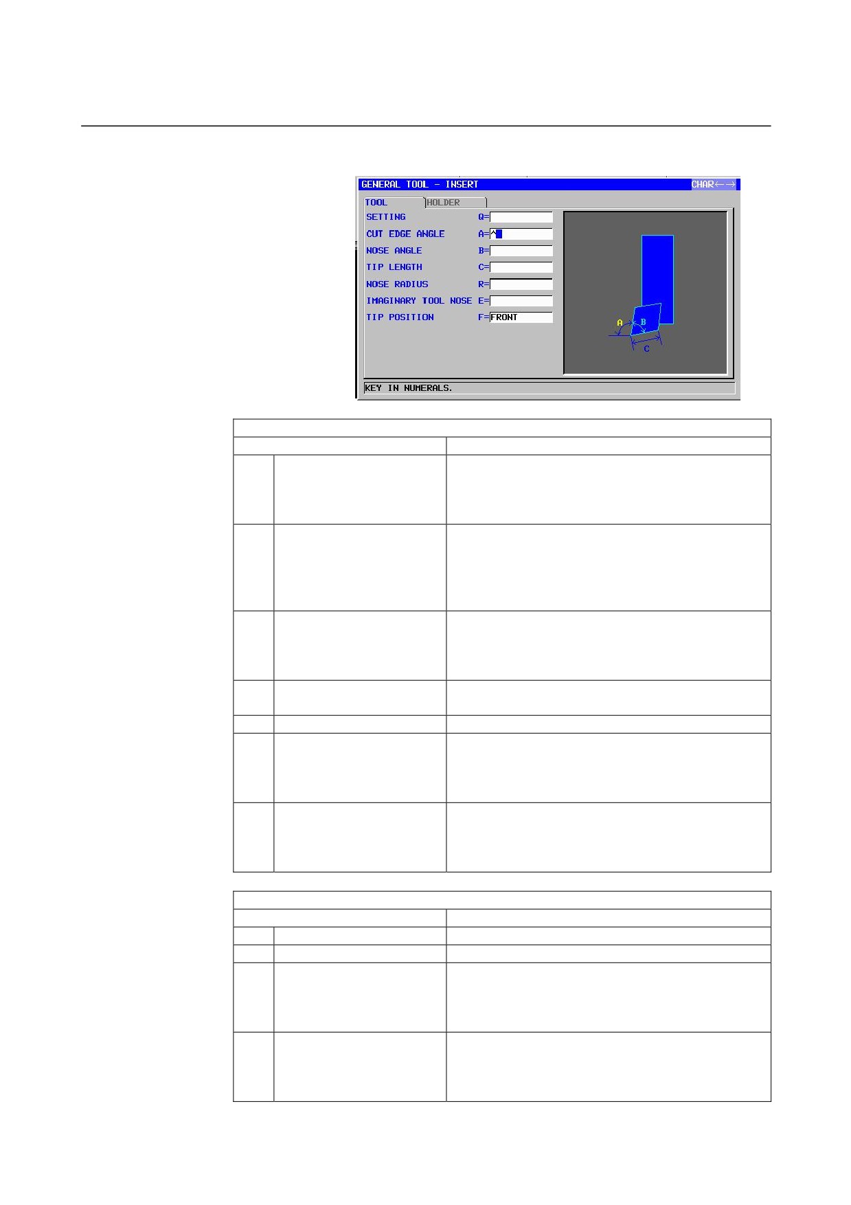
Tool definition block (general tool): G1910
TOOL
Data item
Meaning
Q
SETTING
Tool installation direction. Select the number of an
installation method from the illustration.
Remark) To be selected visually for both vertical and
horizontal lathes.
A
CUT EDGE ANGLE
Angle of the cutting edge (positive value)
Remark) Even when the same tool is used, the
location of the cutting edge angle varies with
the cutting direction (for example, outer
surface machining and end facing).
B
NOSE ANGLE
Angle of the tool nose (positive value)
Remark) Generally, the nose angle remains
unchanged even when the cutting direction
changes.
C
TIP LENGTH
Length of the tool nose portion that can actually cut
(positive value)
R
NOSE RADIUS
Radius of the tool nose (positive value)
E
IMAGINARY TOOL NOSE
Imaginary tool nose position. Select a number from
the menu indicated in the illustration.
Remark) To be selected visually for both vertical and
horizontal lathes.
F
TIP POSITION
[FRONT] : Display the tip in front of the holder. (tool
for forward spindle rotation)
[REAR]
: Display the tip in the rear of the holder.
(tool for reverse spindle rotation)
HOLDER
Data item
Meaning
L*
HOLDER LENGTH
Length of the holder (positive value)
W*
HOLDER WIDTH
Width of the holder (positive value)
I*
HOLDER LENGTH 2
When the tip is installed in the direction opposite to
the holder installation direction, the distance between
the longitudinal end of the holder and tip center
(positive value)
J*
HOLDER WIDTH 2
When the tip is installed in the direction opposite to
the holder installation direction, the distance between
the lateral end of the holder and tip center (positive
value)
- 206 -
B-63874EN/05
OPERATION
9.MACHINING SIMULATION AND DRAWING DURING MACHINING
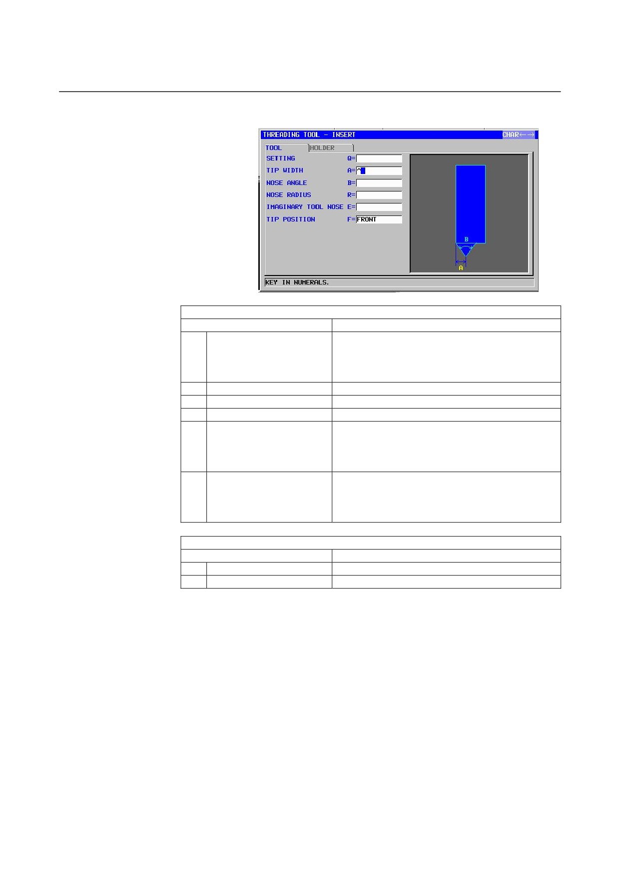
Tool definition block (thread tool): G1911
TOOL
Data item
Meaning
Q
SETTING
Tool installation direction. Select the number of an
installation method from the illustration.
Remark) To be selected visually for both vertical
and horizontal lathes.
A
TIP WIDTH
Tool tip width
B
NOSE ANGLE
Angle of the tool nose (positive value)
R
NOSE RADIUS
Radius of the tool nose (positive value)
E
IMAGINARY TOOL NOSE
Imaginary tool nose position. Select a number from
the menu indicated in the illustration.
Remark) To be selected visually for both vertical
and horizontal lathes.
F
TIP POSITION
[FRONT] : Display the tip in front of the holder. (tool
for forward spindle rotation)
[REAR]
: Display the tip in the rear of the holder.
(tool for reverse spindle rotation)
HOLDER
Data item
Meaning
L*
HOLDER LENGTH
Length of the holder (positive value)
W*
HOLDER WIDTH
Width of the holder (positive value)
- 207 -
9.MACHINING SIMULATION AND DRAWING DURING MACHINING OPERATION
B-63874EN/05
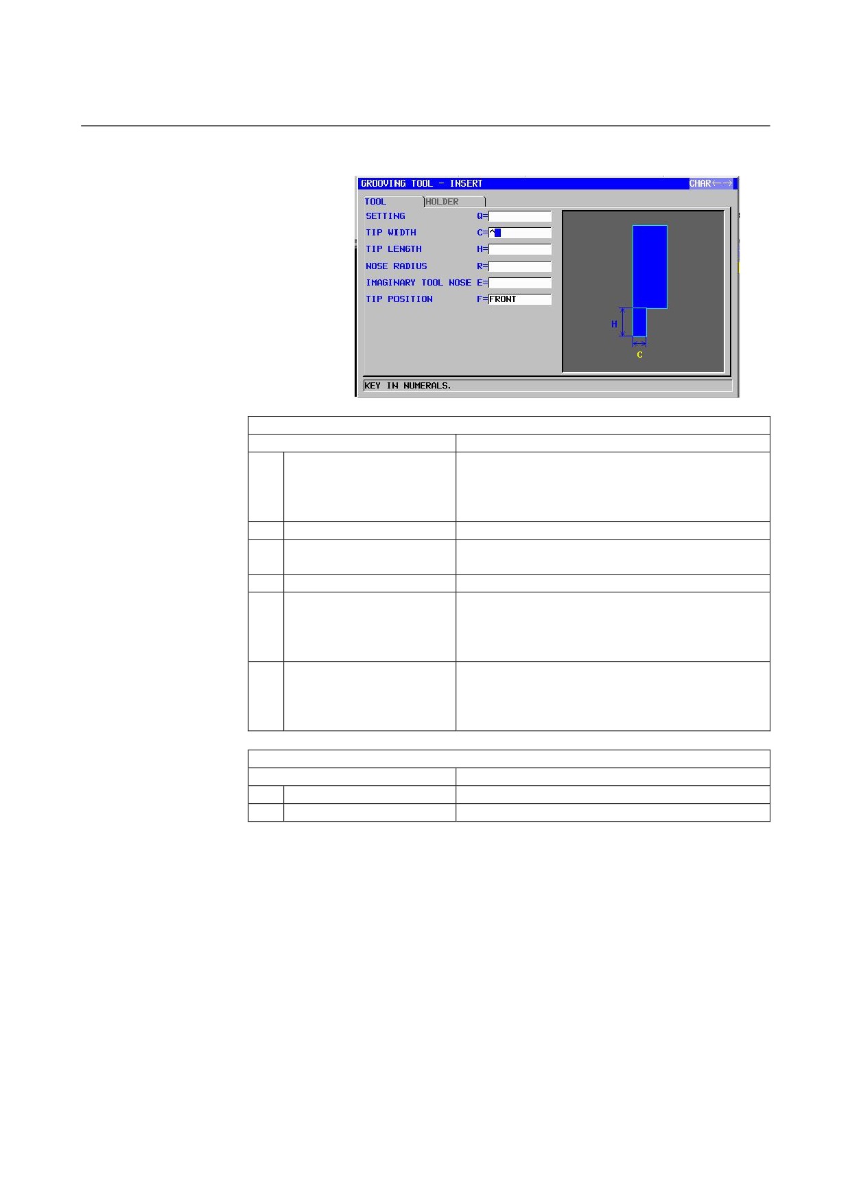
Tool definition block (grooving tool): G1912
TOOL
Data item
Meaning
Q
SETTING
Tool installation direction. Select the number of an
installation method from the illustration.
Remark) To be selected visually for both vertical
and horizontal lathes.
C
TIP WIDTH
Tip width of the grooving tool (positive value)
H
TIP LENGTH
Length of the cutting portion of the grooving tool
(positive value)
R
NOSE RADIUS
Radius of the tool nose (positive value)
E
IMAGINARY TOOL NOSE
Imaginary tool nose position. Select a number from
the menu indicated in the illustration.
Remark) To be selected visually for both vertical
and horizontal lathes.
F
TIP POSITION
[FRONT] : Display the tip in front of the holder. (tool
for forward spindle rotation)
[REAR]
: Display the tip in the rear of the holder.
(tool for reverse spindle rotation)
HOLDER
Data item
Meaning
L*
HOLDER LENGTH
Length of the holder (positive value)
W*
HOLDER WIDTH
Width of the holder (positive value)
- 208 -
B-63874EN/05
OPERATION
9.MACHINING SIMULATION AND DRAWING DURING MACHINING
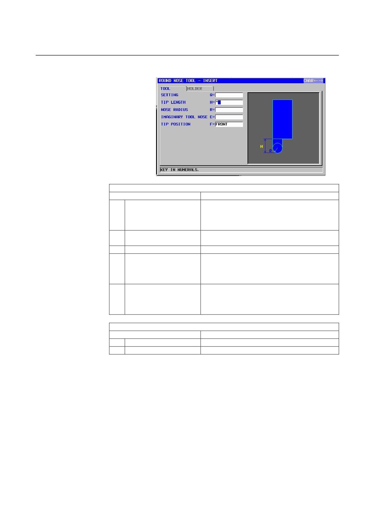
Tool definition block (round tool): G1913
TOOL
Data item
Meaning
Q
SETTING
Tool installation direction. Select the number of an
installation method from the illustration.
Remark) To be selected visually for both vertical
and horizontal lathes.
H
TIP LENGTH
Length of the cutting portion of the round-nose tool
(positive value)
R
NOSE RADIUS
Radius of the tool nose (positive value)
E
IMAGINARY TOOL NOSE
Imaginary tool nose position. Select a number from
the menu indicated in the illustration.
Remark) To be selected visually for both vertical
and horizontal lathes.
F
TIP POSITION
[FRONT] : Display the tip in front of the holder. (tool
for forward spindle rotation)
[REAR]
: Display the tip in the rear of the holder.
(tool for reverse spindle rotation)
HOLDER
Data item
Meaning
L*
HOLDER LENGTH
Length of the holder (positive value)
W*
HOLDER WIDTH
Width of the holder (positive value)
- 209 -
9.MACHINING SIMULATION AND DRAWING DURING MACHINING OPERATION
B-63874EN/05
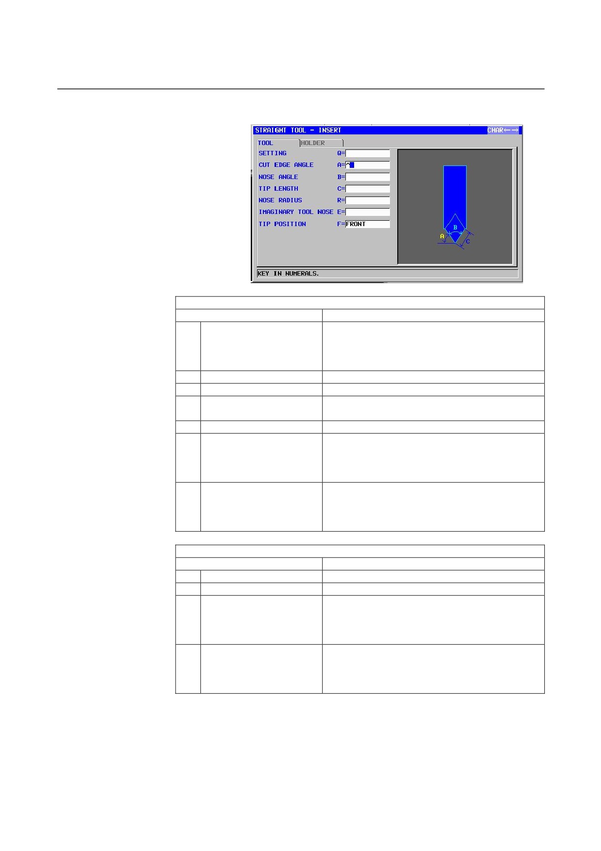
Tool definition block (straight tool): G1914
TOOL
Data item
Meaning
Q
SETTING
Tool installation direction. Select the number of an
installation method from the illustration.
Remark) To be selected visually for both vertical
and horizontal lathes.
A
CUT EDGE ANGLE
Angle of the cutting edge (positive value)
B
NOSE ANGLE
Angle of the tool nose (positive value)
C
TIP LENGTH
Length of the tool nose portion that can actually cut
(positive value)
R
NOSE RADIUS
Radius of the tool nose (positive value)
E
IMAGINARY TOOL NOSE
Imaginary tool nose position. Select a number from
the menu indicated in the illustration.
Remark) To be selected visually for both vertical
and horizontal lathes.
F
TIP POSITION
[FRONT] : Display the tip in front of the holder. (tool
for forward spindle rotation)
[REAR]
: Display the tip in the rear of the holder.
(tool for reverse spindle rotation)
HOLDER
Data item
Meaning
L*
HOLDER LENGTH
Length of the holder (positive value)
W*
HOLDER WIDTH
Width of the holder (positive value)
I*
HOLDER LENGTH 2
When the tip is installed in the direction opposite to
the holder installation direction, the distance
between the longitudinal end of the holder and tip
center (positive value)
J*
HOLDER WIDTH 2
When the tip is installed in the direction opposite to
the holder installation direction, the distance
between the lateral end of the holder and tip center
(positive value)
- 210 -
B-63874EN/05
OPERATION
9.MACHINING SIMULATION AND DRAWING DURING MACHINING
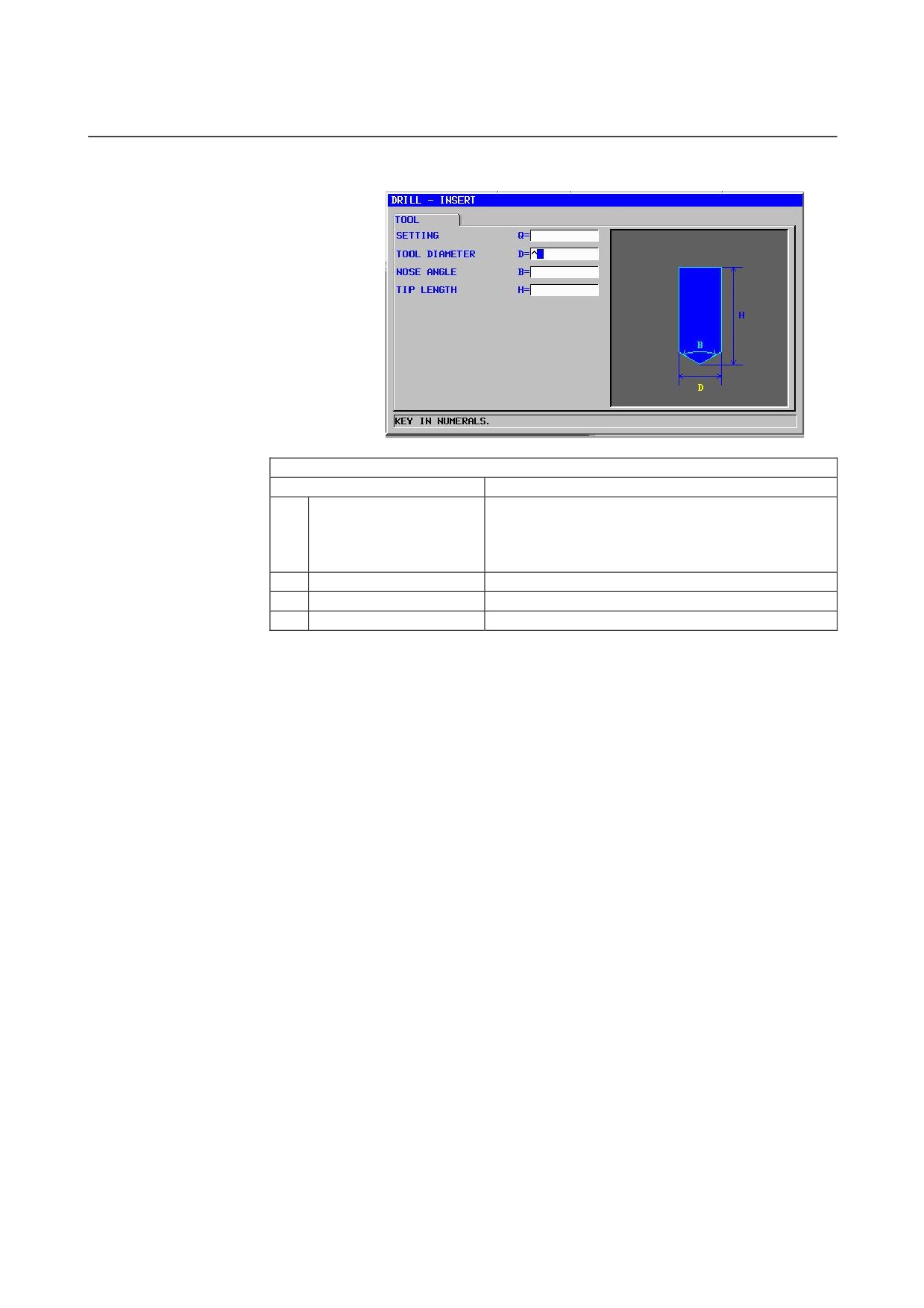
Tool definition block (drill): G1921
TOOL
Data item
Meaning
Q
SETTING
Tool installation direction. Select the number of an
installation method from the illustration.
Remark) To be selected visually for both vertical and
horizontal lathes.
D
TOOL DIAMETER
Drill diameter (positive value)
B
NOSE ANGLE
Drill nose angle (positive value)
H
TIP LENGTH
Drill length (positive value)
- 211 -
9.MACHINING SIMULATION AND DRAWING DURING MACHINING OPERATION
B-63874EN/05
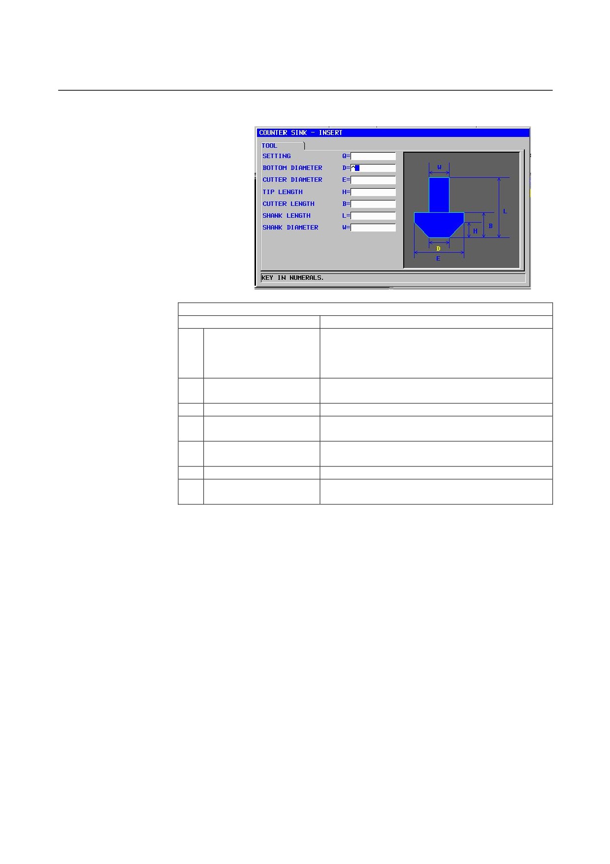
Tool definition block (counter sink tool): G1931
TOOL
Data item
Meaning
Q
SETTING
Tool installation direction. Select the number of an
installation method from the illustration.
Remark) To be selected visually for both vertical and
horizontal lathes.
D
BOTTOM DIAMETER
Diameter of the end of the counter sink tool end
(positive value)
E
CUTER DIAMETER
Diameter of the counter sink tool (positive value)
H
TIP LENGTH
Length of the cutting portion of the counter sink tool
(tool axis direction, positive value)
B
CUTTER LENGTH
Cutter length of the counter sink tool (tool axis
direction, positive value)
L
SHANK LENGTH
Entire length of the counter sink tool (positive value)
W
SHANK DIAMETER
Diameter of the shank of the counter sink tool (positive
value)
- 212 -
B-63874EN/05
OPERATION
9.MACHINING SIMULATION AND DRAWING DURING MACHINING
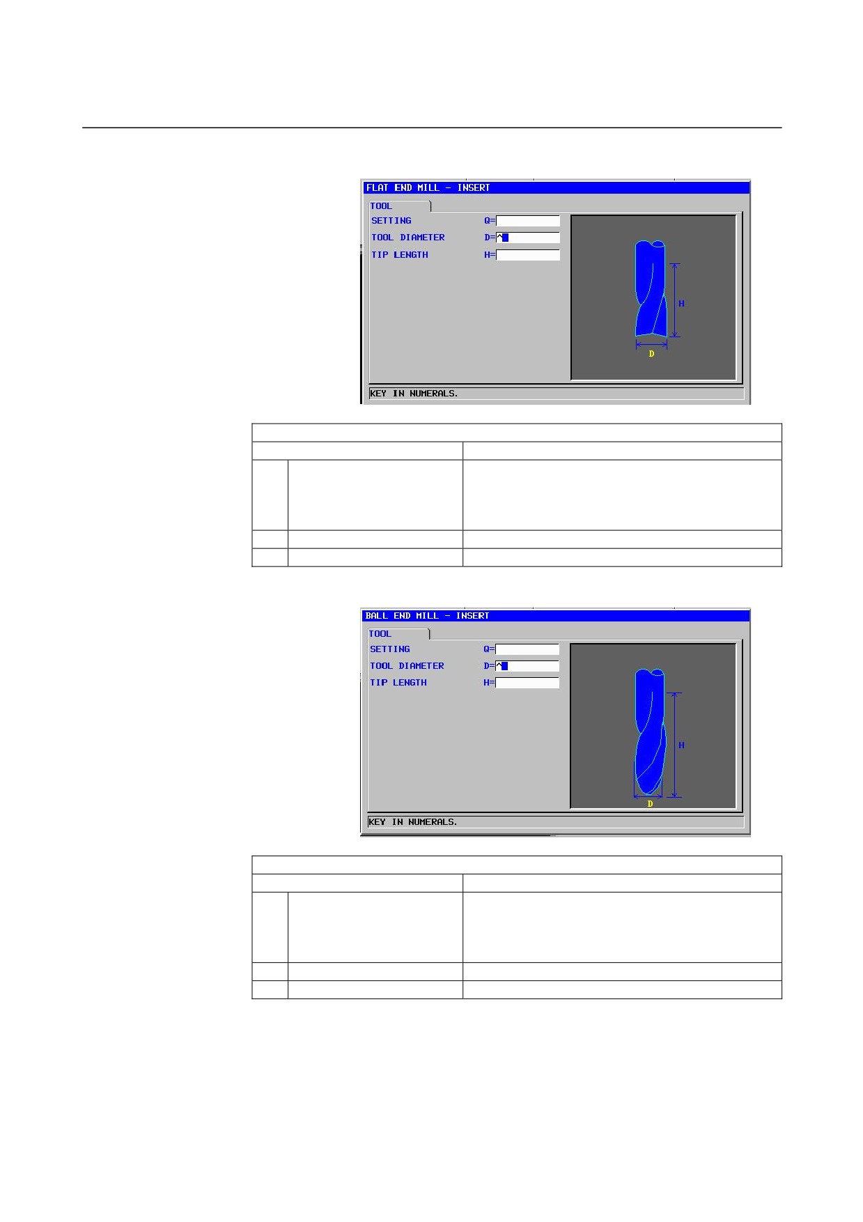
Tool definition block (flat end mill): G1932
TOOL
Data item
Meaning
Q
SETTING
Tool installation direction. Select the number of an
installation method from the illustration.
Remark) To be selected visually for both vertical
and horizontal lathes.
D
TOOL DIAMETER
End mill diameter (positive value)
H
TIP LENGTH
End mill tool length (positive value)
Tool definition block (ball end mill): G1933
TOOL
Data item
Meaning
Q
SETTING
Tool installation direction. Select the number of an
installation method from the illustration.
Remark) To be selected visually for both vertical
and horizontal lathes.
D
TOOL DIAMETER
End mill diameter (positive value)
H
TIP LENGTH
End mill tool length (positive value)
- 213 -
9.MACHINING SIMULATION AND DRAWING DURING MACHINING OPERATION
B-63874EN/05
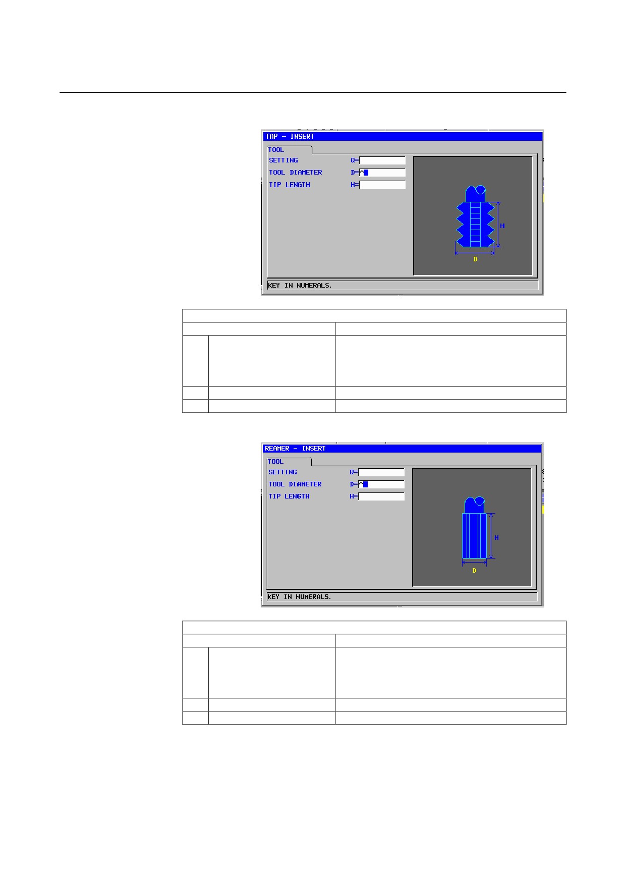
Tool definition block (tap): G1922
TOOL
Data item
Meaning
Q
SETTING
Tool installation direction. Select the number of an
installation method from the illustration.
Remark) To be selected visually for both vertical
and horizontal lathes.
D
TOOL DIAMETER
Tap diameter (positive value)
H
TIP LENGTH
Tap length (positive value)
Tool definition block (reamer): G1923
TOOL
Data item
Meaning
Q
SETTING
Tool installation direction. Select the number of an
installation method from the illustration.
Remark) To be selected visually for both vertical
and horizontal lathes.
D
TOOL DIAMETER
Reamer diameter (positive value)
H
TIP LENGTH
Reamer length (positive value)
- 214 -
B-63874EN/05
OPERATION
9.MACHINING SIMULATION AND DRAWING DURING MACHINING
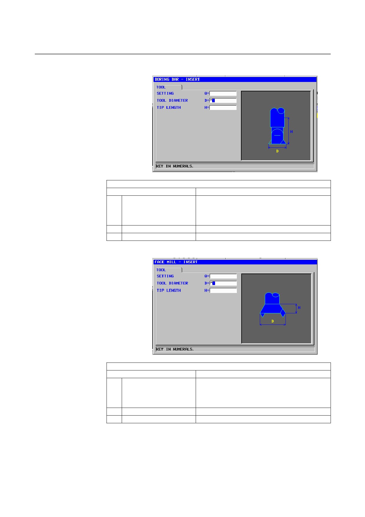
Tool definition block (boring tool): G1924
TOOL
Data item
Meaning
Q
SETTING
Tool installation direction. Select the number of an
installation method from the illustration.
Remark) To be selected visually for both vertical
and horizontal lathes.
D
TOOL DIAMETER
Boring tool diameter (positive value)
H
TIP LENGTH
Boring tool length (positive value)
Tool definition block (face mill): G1930
TOOL
Data item
Meaning
Q
SETTING
Tool installation direction. Select the number of an
installation method from the illustration.
Remark) To be selected visually for both vertical
and horizontal lathes.
D
TOOL DIAMETER
Face mill diameter (positive value)
H
TIP LENGTH
Face mill length (positive value)
- 215 -
9.MACHINING SIMULATION AND DRAWING DURING MACHINING OPERATION
B-63874EN/05
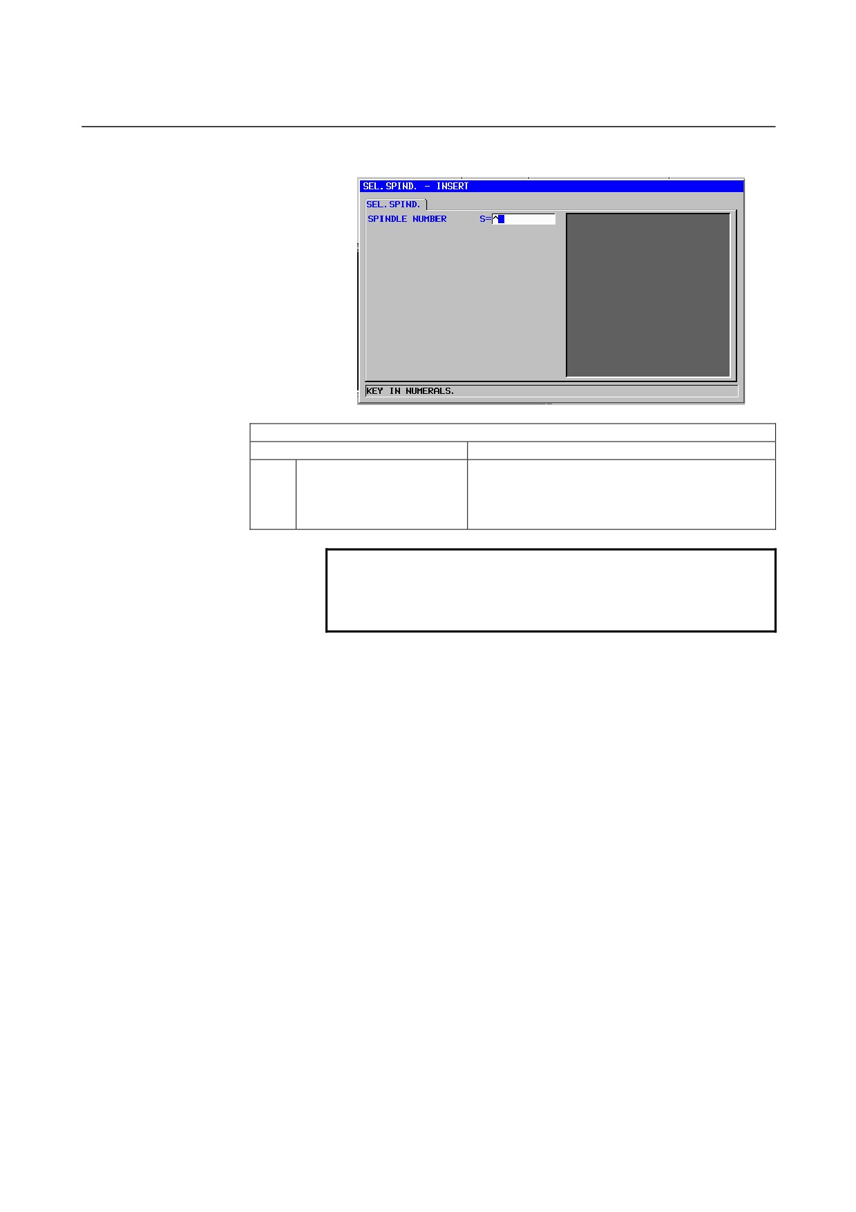
Spindle selection block: G1998
SEL. SPIND.
Data item
Meaning
S
SPINDLE NUMBER
Spindle number of a subspindle (positive number)
Remark) Enter 2 when the subspindle has the
spindle number 2. Enter 3 when the
subspindle has the spindle number 3.
NOTE
The menu above is prepared for a machine with a
subspindle, and is displayed when bit 1 of
parameter No. 14702 = 1.
- 216 -
B-63874EN/05
OPERATION
9.MACHINING SIMULATION AND DRAWING DURING MACHINING
9.10
SPINDLE MOVEMENT ANIMATION FOR AUTOMATIC
LATHES
This is the additional animation function to simulate machining that
utilizes movement of spindle for automatic lathes.
The option of “spindle movement animation for automatic lathe” is
necessary to use this function.
NOTE
This function is available for only Series 16i/18i/21i.
9.10.1
Function
If the command that reflects movement of master in movement of
slave is entered in program and the command is executed, slave
tool moves too. From this movement, machining that utilizes
movement of spindle will be simulated.
9.10.2
Start Command of Reflection
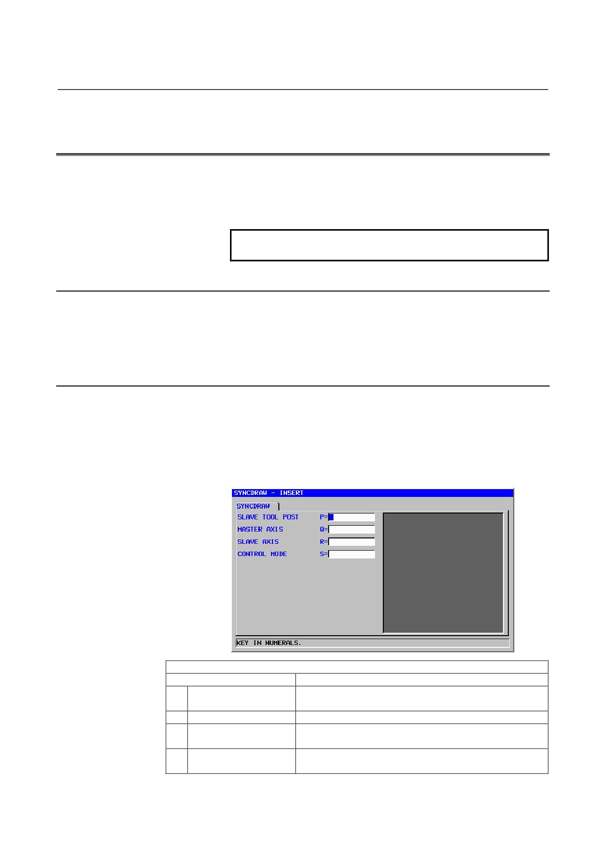
The “SYNCDRAW” tab will be displayed by pressing [START]. The
following window for inputting start command of reflection will be
displayed, after the
“SYNCDRAW” tab is selected, the cursor is
placed on “START SYNCHRONIZ-ATION CONTROL” and INPUT
key is pushed. The reflection in slave starts by the command.
Start command of reflection : G1994
Condition
Data item
Meaning
P
SLAVE TOOL POST
Number of slave tool post in which Manual Guide i reflects
movement of master.
Q
MASTER AXIS
Number of axis that is reflected (X, Y, Z, or C axis)
R
SLAVE AXIS
Number of axis in which Guide i reflects movement of
master (X, Y, Z, or C axis)
S
CONTROL MODE
[SYNC]:Under synchronization control mode
[NOSYNC]:Not Under synchronization control mode
- 217 -
9.MACHINING SIMULATION AND DRAWING DURING MACHINING OPERATION
B-63874EN/05
9.10.3 End Command of Reflection
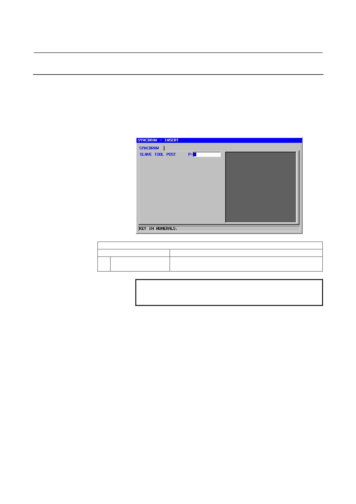
The following window for inputting end command of reflection will
be displayed, after the cursor is placed on
“END
SYNCHRONIZATION CONTROL” in the “SYNCDRAW” tab and
INPUT key is pushed. The reflection in slave finishes by the
command.
End command of reflection : G1995
Condition
Data item
Meaning
P
SLAVE TOOL POST
Number of slave tool post in which Manual Guide i reflects
movement of master.
NOTE
1 Setting the parameter No27310#5 to “1” is
necessary to display “SYNCDRAW” tab.
- 218 -
B-63874EN/05
OPERATION
9.MACHINING SIMULATION AND DRAWING DURING MACHINING
9.10.4 Simulation and Actual Working of the Machine
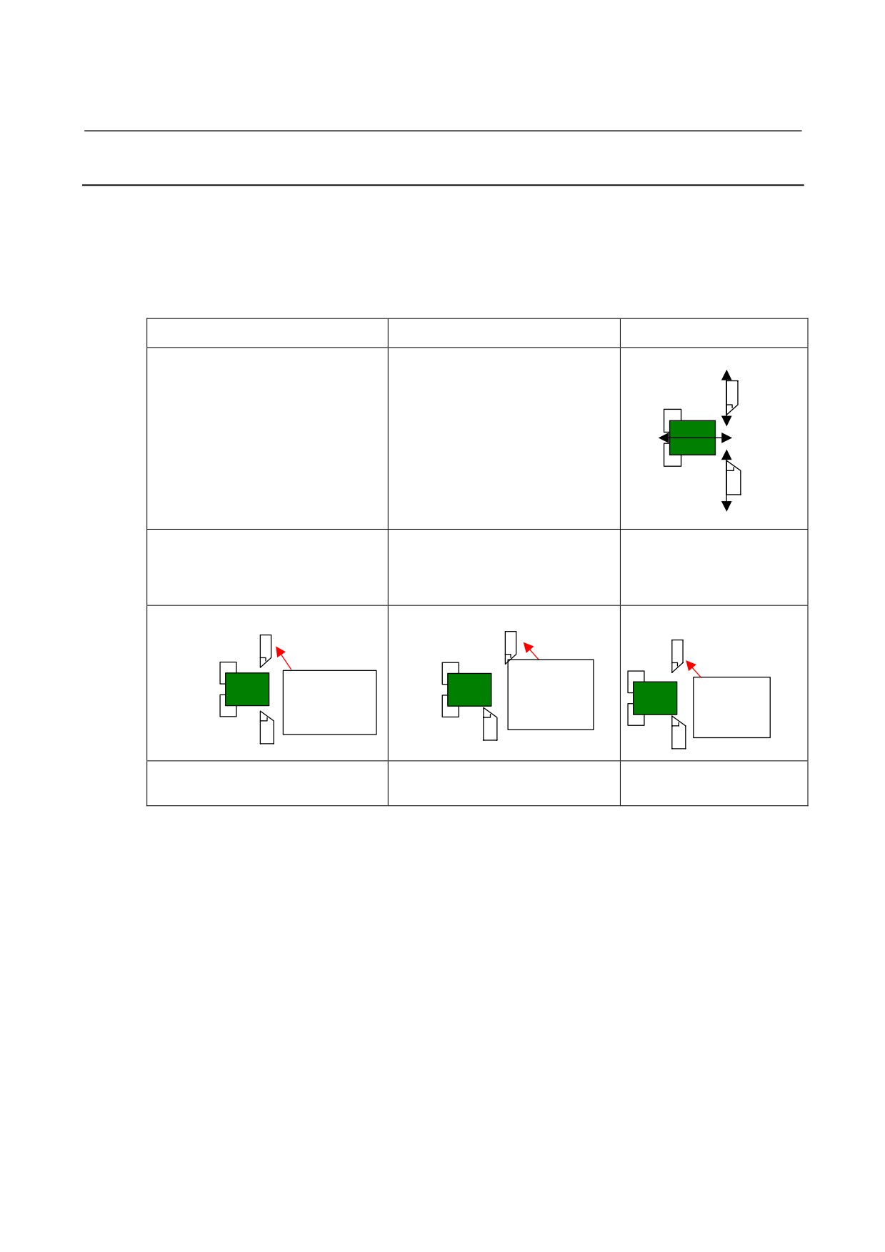
Between G1994 and G1995, the movement of axis number that is
designated at Q is reflected in the movement of axis that is designated
by R. And R is a number of tool post that is designated by P.
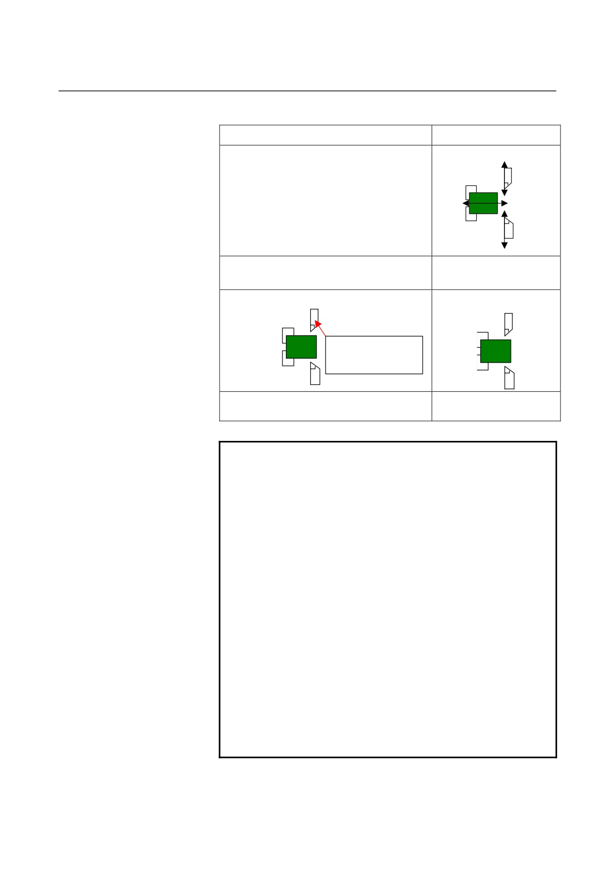
Ex1. Working not under synchronous, composite, or superimposed
control
Path-1(There is reflect command)
Path-1(There isn’t reflect command)
Working of actual machine
Not under synchronous, composite, or
Not under synchronous, composite,
+X3
superimposed control
or superimposed control
Path-3
-X3
-Z
+Z
-X1
Path-1
+X1
G1994 P3.Q2. R2. S0.;
There isn’t command.
Reflect movement of path-1
second axis (Z-axis) in movement
of path-3 second axis (Z-axis).
[Display in animation]
[Display in animation]
Move Z axis
Move Z axis
Tool pos is
Tool pos isn’t
off and abs
Abs pos
off and abs
pos doesn’t
doesn’t
pos doesn’t
change.
change.
change.
G1995 P3.;
There isn’t command.
End reflection in path-3.
- 219 -
9.MACHINING SIMULATION AND DRAWING DURING MACHINING OPERATION
B-63874EN/05
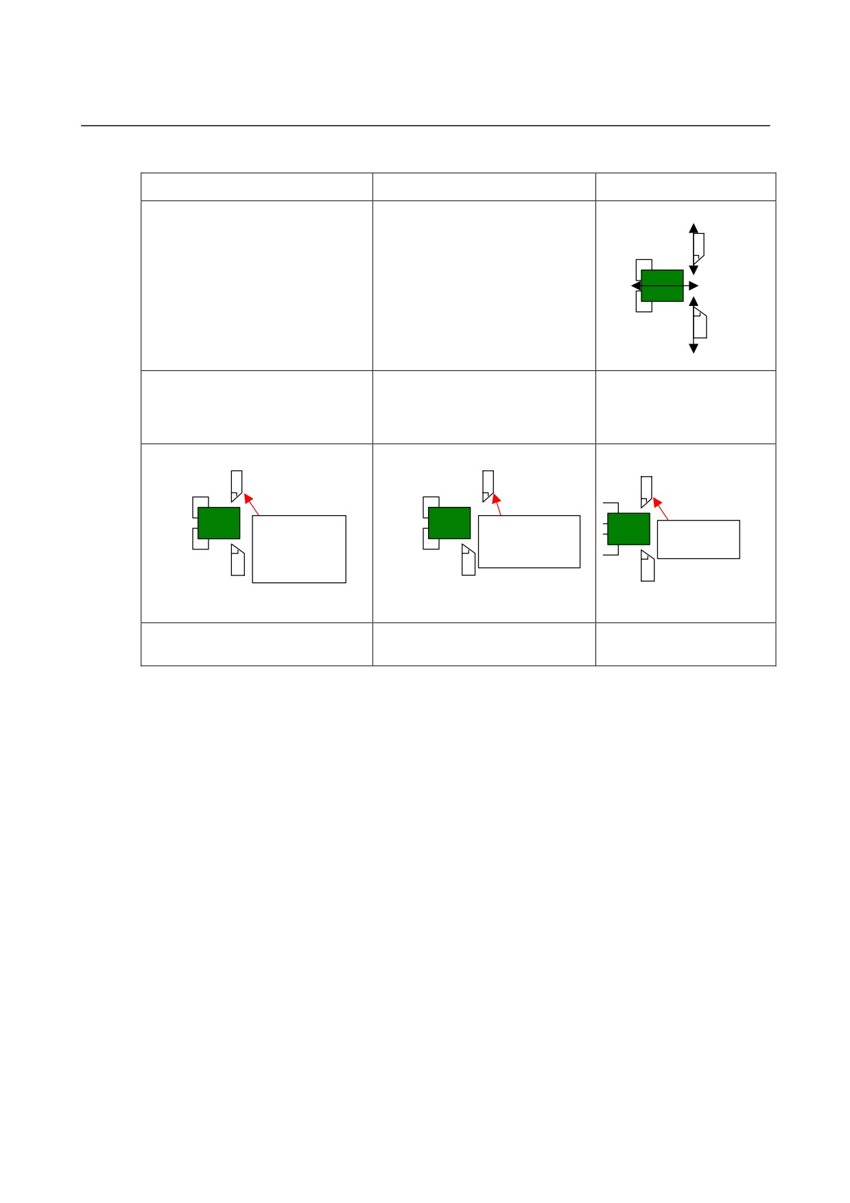
Ex.2 Working under synchronization control
Path-1(There isn’t reflect command)
Path-1(There isn’t reflect command)
Working of actual machine
Under synchronization control
Under synchronization control
+X3
Path-3
-X3
-Z
+Z
-X1
Path-1
+X1
G1994 P3.Q2. R2. S1.;
There isn’t command.
Reflect movement of path-1
second axis (Z-axis) in movement
of path-3 second axis (Z-axis).
[Display in animation]
[Display in animation]
Move Z axis
Move Z axis
Tool pos isn’t
Tool pos is off
Abs pos
off and abs
and abs pos
changes.
pos don’t
doesn’t change.
change.
G1995 P3.;
There isn’t command.
End reflection in path-3.
- 220 -
B-63874EN/05
OPERATION
9.MACHINING SIMULATION AND DRAWING DURING MACHINING
Ex3. Working under composite control or superimposed control
Working of actual machine
Path-1(There isn’t reflect command)
+X3
Under composite control or superimposed
control
Path-3
-X3
-Z
+Z
-X1
Path-1
+X1
G1995 P3.;
End reflection in path-3.
[Display in animation]
Move Z axis
Tool pos isn’t off. Abs
pos changes.
Not under composite control or superimposed
control
NOTE
1 The option of spindle movement animation for
automatic lathe is necessary to use this function.
2 Set parameter No.27311#1 to “1” when this function
is used.
3 Master axis must be only basic three axes and C axis.
And slave axis must be the same axis as master.
4 In animation, slave absolute axis isn’t renewed though
under Synchronization control (S1. is commanded in
G1994).
5 When machining simulation is finished by reset key as
so on, the reflection will be canceled.
6 Master tool post can’t become slave tool post though
G1994 that designates the tool post as the slave is
command from other tool post.
7 During reflecting movement, when second start
command of reflection is executed and control mode
that is designated by second command is different
from former one, former start command will be
canceled. When control mode is same as former one,
slave axis will be newly added and former command
won’t be canceled.
- 221 -