FANUC MANUAL GUIDE i. OPERATOR’S MANUAL - page 6
5.DETAILED DESCRIPTIONS ABOUT ENTERING ARBITRARY FIGURES OPERATION
B-63874EN/05
NOTE
1
‘INPUT DATA’ means the items, which are
displayed on the input data window in editing or
altering.
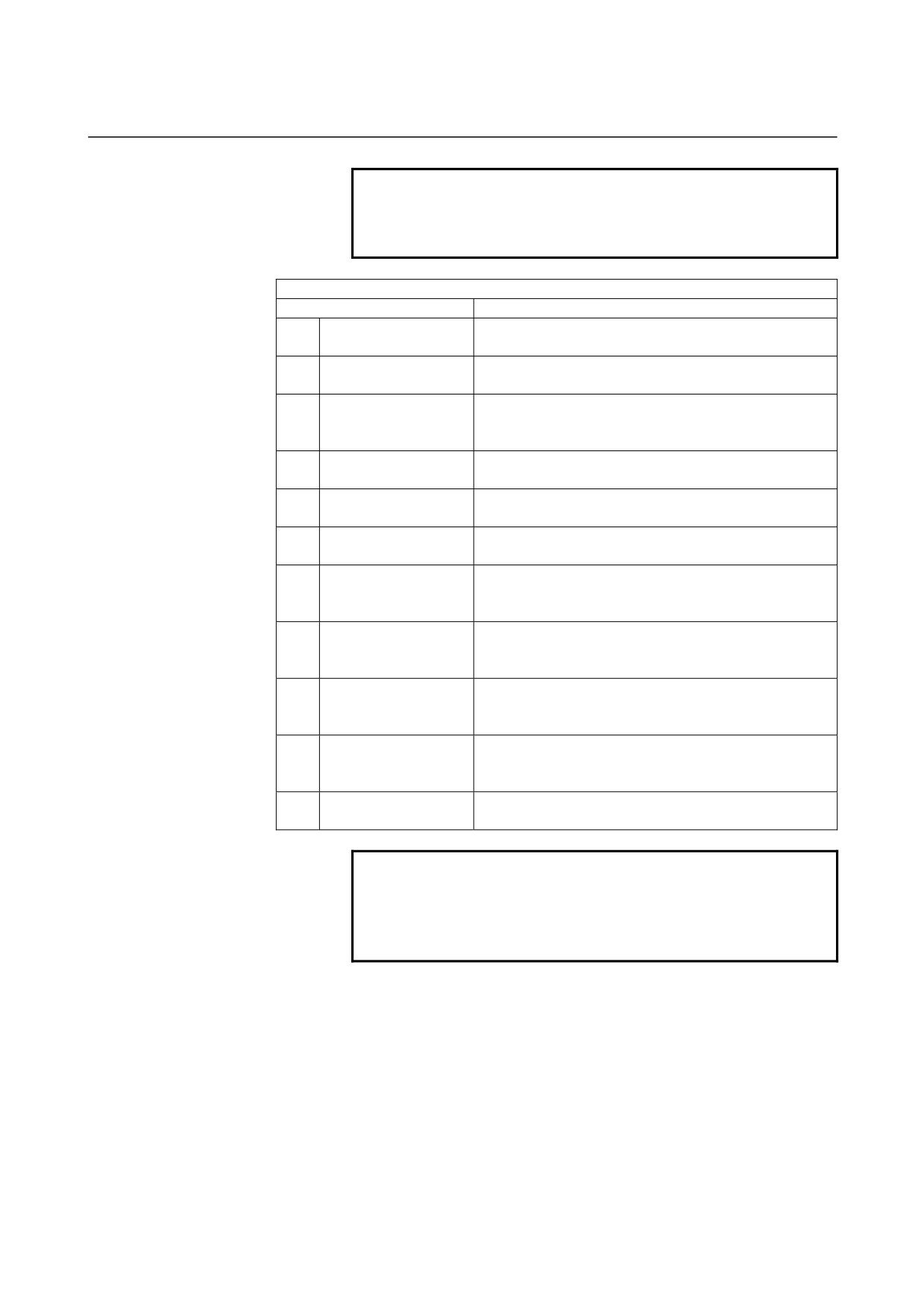
ELEMENT & ATTRIBUTE
(OUTPUT DATA)
(Note 2)
Data item
Meaning
H
END POINT X
X coordinate of the end point of a straight line
(calculation result)
V
END POINT Z
Z coordinate of the end point of a straight line
(calculation result)
K
LINE DIRECTION
The direction of a straight line is selected from a menu
indicated on a soft key.
(input value)
C*
END POINT DX
X coordinate of the end point of a straight line
(input value)
D*
END POINT Z
Z coordinate of the end point of a straight line
(input value)
A*
ANGLE
Straight-line angle
(input value)
L
LAST CONNECTION
[1] : In contact with the immediately preceding figure
[0] : Not in contact with the immediately preceding figure
(input value)
M
NEXT CONNECTION
[1] : In contact with the immediately following figure
[0] : Not in contact with the immediately following figure
(input value)
T
ELEMENT TYPE
[1] : Cut as parts
[2] : Cut as a blank portion
(input value)
S
SELECT FIG. INFO.
In the case of plural intersection or contact, the operator
sets a candidate.
(input value)
F
FINISH FEEDRATE
Cutting feedrate for finishing
(input value)
NOTE
2
‘OUTPUT DATA’ means the items, which are
displayed on the program window as creating
program. It can be referenced only for program
display purposes.
- 132 -
B-63874EN/05
OPERATION 5.DETAILED DESCRIPTIONS ABOUT ENTERING ARBITRARY FIGURES
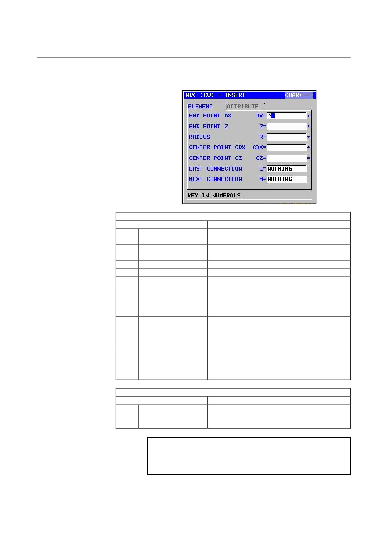
Arc (CW): G1452 (ZX plane)
Arc (CCW): G1453 (ZX plane)
ELEMENT
(INPUT DATA)
(Note 1)
Data item
Meaning
DX*
END POINT DX
X coordinate of an arc end point
Remarks) Incremental programming is possible.
Z*
END POINT Z
Z coordinate of an arc end point
Remarks) Incremental programming is possible.
R*
RADIUS
Arc radius
CDX*
CENTER POINT CDX
X coordinate of an arc center
CZ*
CENTER POINT CZ
Z coordinate of an arc center
L
LAST CONNECTION
[TANGNT] : In contact with the immediately
preceding figure
[NO SET]
: Not in contact with the immediately
preceding figure (initial value)
M
NEXT CONNECTION
[TANGNT] : In contact with the immediately
following figure
[NO SET]
: Not in contact with the immediately
following figure (initial value)
T
ELEMENT TYPE
[PART]
: Cut as parts
[BLANK] : Cut as a blank portion
Remarks) The system sets the last data as an initial
value.
ATTRIBUTE
(INPUT DATA)
(Note 1)
Data item
Meaning
F
FINISH FEEDRATE
Cutting feedrate for finishing (positive value)
Remarks) It is possible to set the feedrate to each
block on Finishing.
NOTE
1
‘INPUT DATA’ means the items, which are
displayed on the input data window in editing or
altering.
- 133 -
5.DETAILED DESCRIPTIONS ABOUT ENTERING ARBITRARY FIGURES OPERATION
B-63874EN/05
ELEMENT & ATTRIBUTE
(OUTPUT DATA)
(Note 2)
Data item
Meaning
H
END POINT X
X coordinate of an arc end point (calculation result)
V
END POINT Z
Z coordinate of an arc end point (calculation result)
R
RADIUS
Arc radius
(calculation result)
I
CENTER POINT X
X coordinate of an arc center
(calculation result)
J
CENTER POINT Z
Z coordinate of an arc center
(calculation result)
C*
END POINT X
X coordinate of an arc end point
(input value)
D*
END POINT Z
Z coordinate of an arc end point
(input value)
E*
RADIUS
Arc radius
(input value)
P*
CENTER POINT CDX
X coordinate of an arc center
(input value)
Q*
CENTER POINT CZ
Z coordinate of an arc center
(input value)
L
LAST CONNECTION
[1] : In contact with the immediately preceding figure
[0] : Not in contact with the immediately preceding figure
(input value)
M
NEXT CONNECTION
[1] : In contact with the immediately preceding figure
[0] : Not in contact with the immediately preceding figure
(input value)
T
ELEMENT TYPE
[1] : Cut as parts
[2] : Cut as a blank portion
(input value)
S
SELECT FIG. INFO.
In the case of plural intersection or contact, the operator
sets a candidate.
(input value)
F
FINISH FEEDRATE
Cutting feedrate for finishing
(input value)
NOTE
2
‘OUTPUT DATA’ means the items, which are
displayed on the program window as creating
program. It can be referenced only for program
display purposes.
- 134 -
B-63874EN/05
OPERATION 5.DETAILED DESCRIPTIONS ABOUT ENTERING ARBITRARY FIGURES
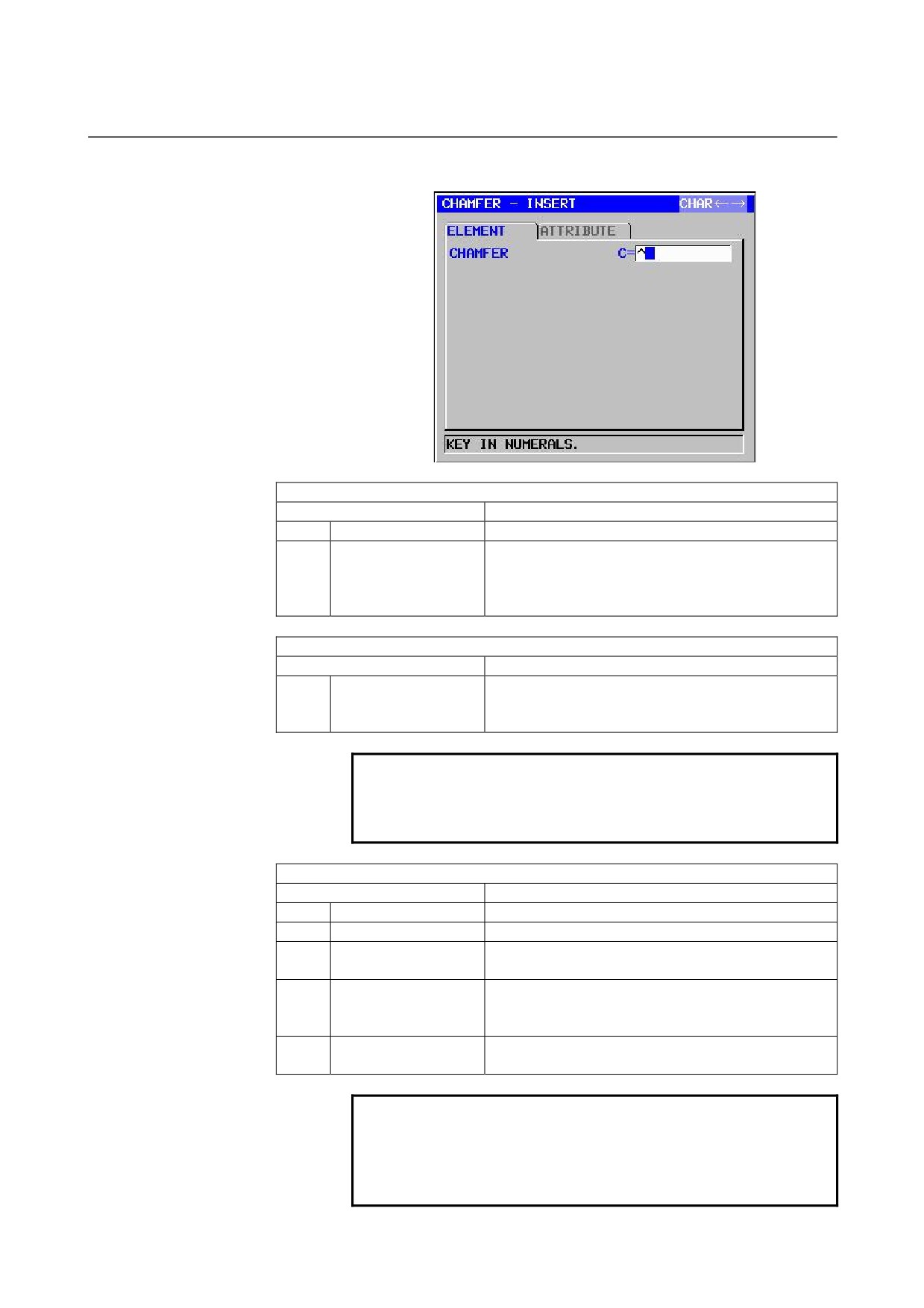
Chamfering: G1454 (ZX plane)
ELEMENT
(INPUT DATA)
(Note 1)
Data item
Meaning
C
CHAMFER
Amount of chamfering (radius value, positive value)
T
ELEMENT TYPE
[PART]
: Cut as parts
[BLANK] : Cut as a blank portion
Remarks) The system sets the last data as an initial
value.
ATTRIBUTE
(INPUT DATA)
(Note 1)
Data item
Meaning
F
FINISH FEEDRATE
Cutting feedrate for finishing (positive value)
Remarks) It is possible to set the feedrate to each
block on Finishing.
NOTE
1
‘INPUT DATA’ means the items, which are
displayed on the input data window in editing or
altering.
ELEMENT & ATTRIBUTE
(OUTPUT DATA)
(Note 2)
Data item
Meaning
H
END POINT X
X coordinate of an arc end point
(calculation result)
V
END POINT Z
Z coordinate of an arc end point
(calculation result)
C
CHAMFER
Amount of chamfering (radius value, positive value)
(input value)
T
ELEMENT TYPE
[1] : Cut as parts
[2] : Cut as a blank portion
(input value)
F
FINISH FEEDRATE
Cutting feedrate for finishing
(input value)
NOTE
2
‘OUTPUT DATA’ means the items, which are
displayed on the program window as creating
program. It can be referenced only for program
display purposes.
- 135 -
5.DETAILED DESCRIPTIONS ABOUT ENTERING ARBITRARY FIGURES OPERATION
B-63874EN/05
NOTE
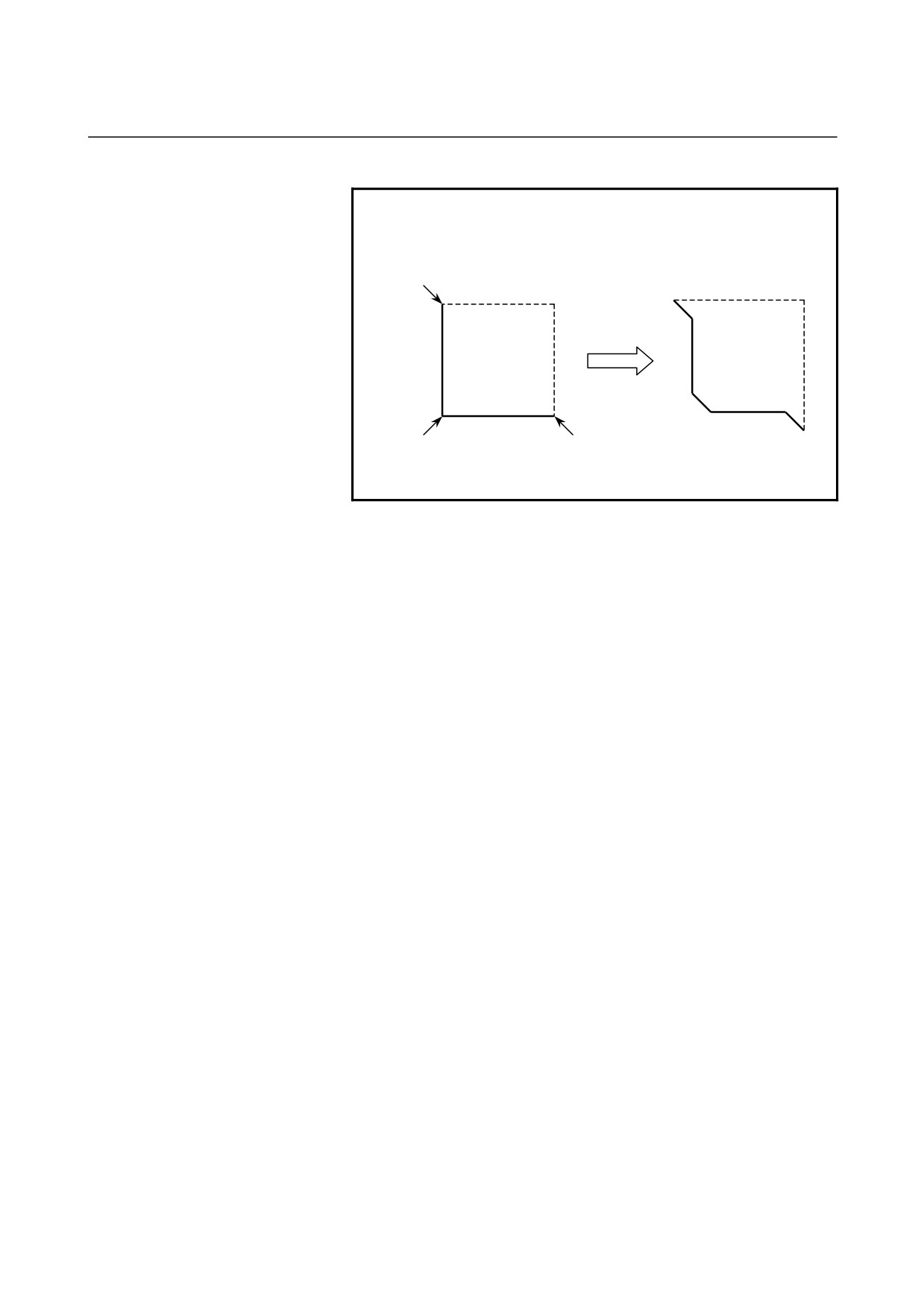
3 By setting the parameter No.14851#0=1, Corner
element between a blank element and a part
element can be created in the opposite direction.
C
C
C
C
C
C
Dotted line : blank element
Normal line : part element
- 136 -
B-63874EN/05
OPERATION 5.DETAILED DESCRIPTIONS ABOUT ENTERING ARBITRARY FIGURES
Corner rounding: G1455 (ZX plane)
ELEMENT
(INPUT DATA)
(Note 1)
Data item
Meaning
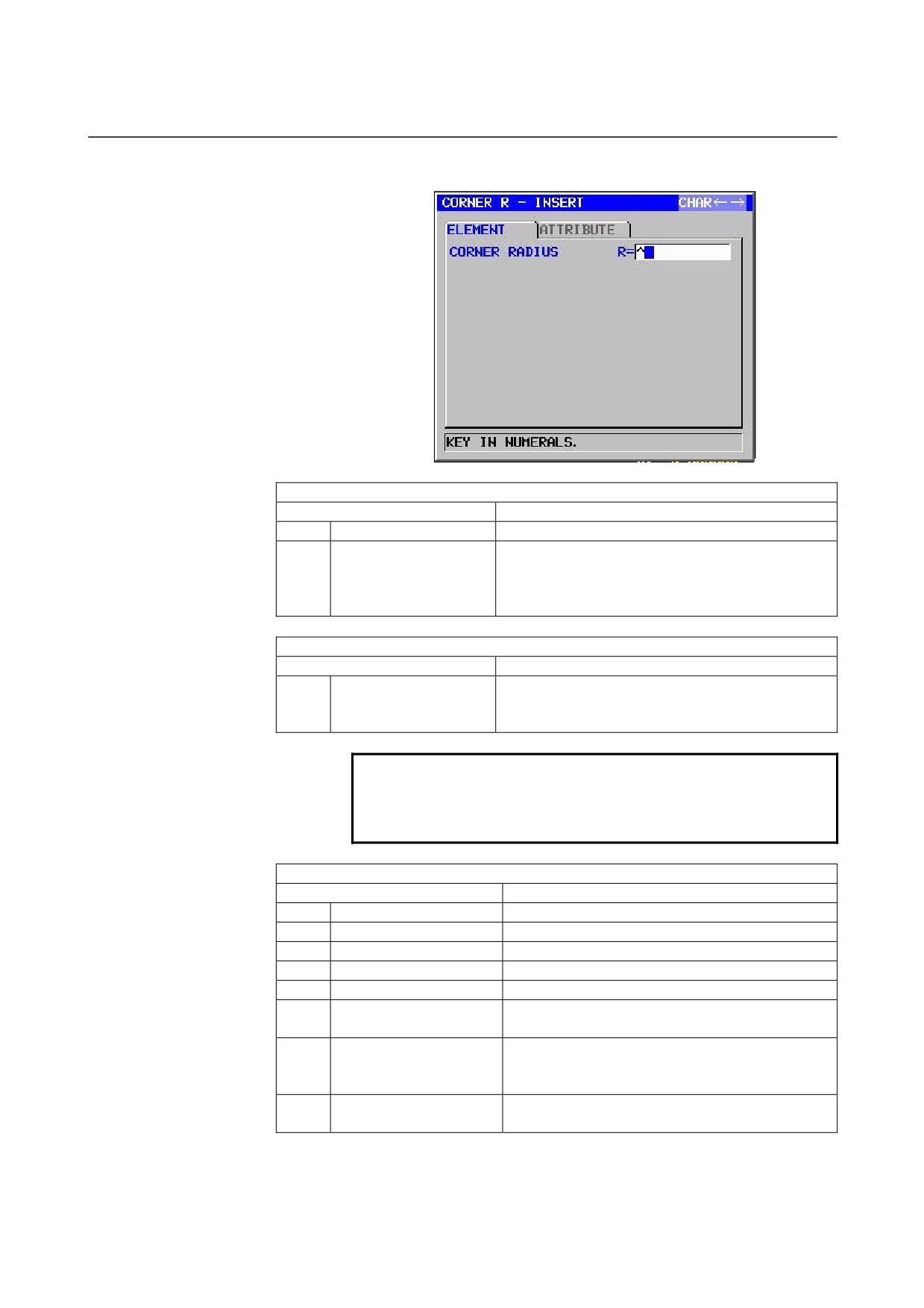
R
CORNER RADIUS
Corner rounding (radius value, positive value)
T
ELEMENT TYPE
[PART]
: Cut as parts
[BLANK] : Cut as a blank portion
Remarks) The system sets the last data as an initial
value.
ATTRIBUTE
(INPUT DATA)
(Note 1)
Data item
Meaning
F
FINISH FEEDRATE
Cutting feedrate for finishing (positive value)
Remarks) It is possible to set the feedrate to each
block on Finishing.
NOTE
1
‘INPUT DATA’ means the items, which are
displayed on the input data window in editing or
altering.
ELEMENT & ATTRIBUTE
(OUTPUT DATA)
(Note 2)
Data item
Meaning
H
END POINT X
X coordinate of an arc end point (calculation result)
V
END POINT Z
Z coordinate of an arc end point (calculation result)
R
RADIUS
Arc radius
(calculation result)
I
CENTER POINT X
X coordinate of an arc center
(calculation result)
J
CENTER POINT Z
Z coordinate of an arc center
(calculation result)
K
ROTATION DIRECTION
[2] : Clockwise
[3] : Counterclockwise
T
ELEMENT TYPE
[1] : Cut as parts
[2] : Cut as a blank portion
(input value)
F
FINISH FEEDRATE
Cutting feedrate for finishing
(input value)
- 137 -

5.DETAILED DESCRIPTIONS ABOUT ENTERING ARBITRARY FIGURES OPERATION
B-63874EN/05
NOTE
2
‘OUTPUT DATA’ means the items, which are
displayed on the program window as creating
program. It can be referenced only for program
display purposes.
3 By setting the parameter No.14851#0=1, Corner
element between a blank element and a part
element can be created in the opposite direction.
End of arbitrary figures: G1456 (ZX plane)
This block is output at the end of a series of arbitrary-figure blocks.
NOTE
A series of arbitrary figures must be enclosed
between G1450 (start point) and G1456 (end of
arbitrary figures).
- 138 -
B-63874EN/05
OPERATION 5.DETAILED DESCRIPTIONS ABOUT ENTERING ARBITRARY FIGURES
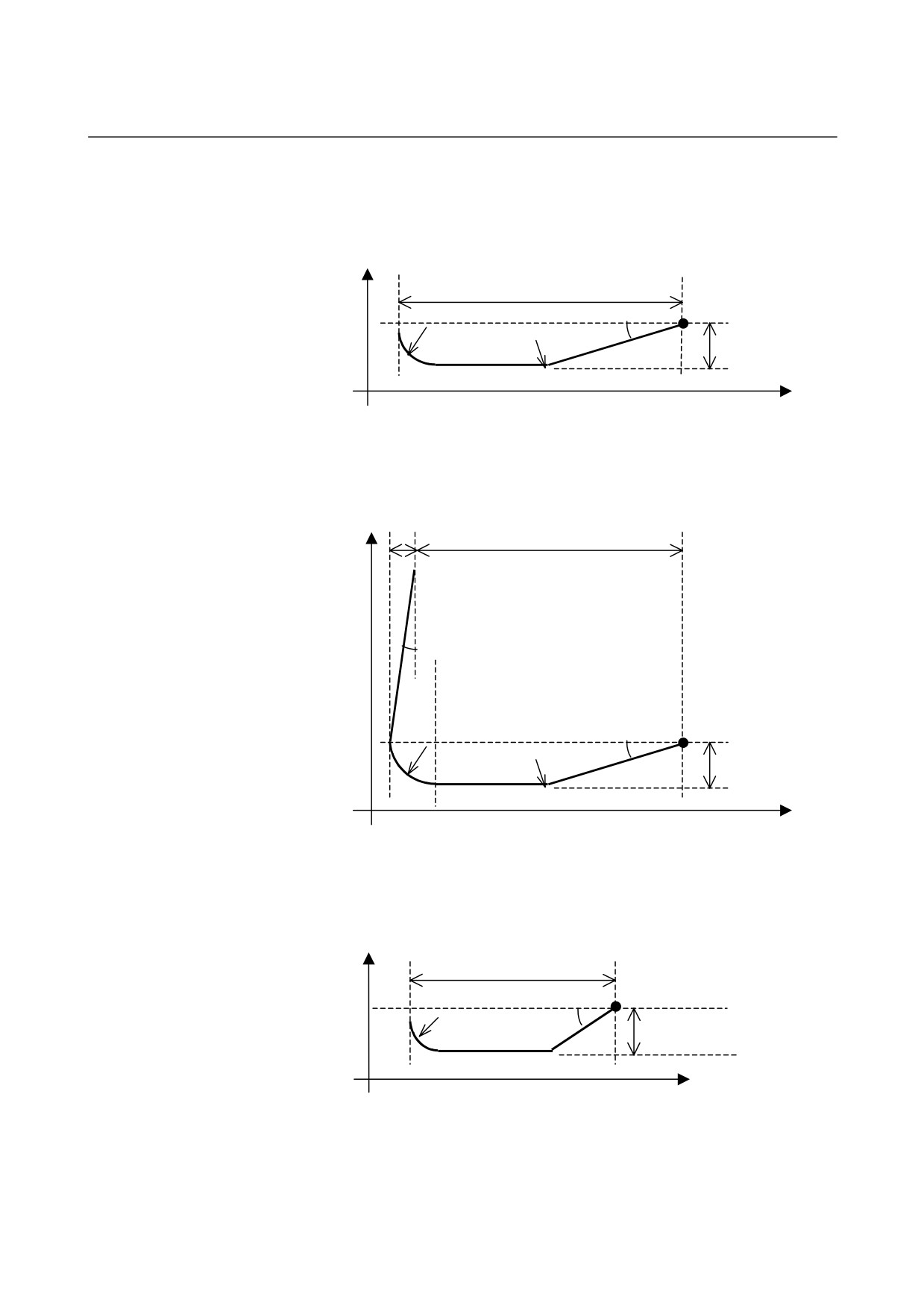
DIN509 :
Pressing the [DIN509] soft key displays the sub-window. By entering
necessary data, a neck figure for DIN509 can be created.
X
w
P(z,x)
r
r
15°
d
Z
DIN509F :
Pressing the [D509-F] soft key displays the sub-window. By entering
necessary data, a neck figure for DIN509-F can be created.
X
L
w
8°
P(z, x)
r
15°
d
r
Z
DIN76 :
Pressing the [DIN76] soft key displays the sub-window. By entering
necessary data, a neck figure for DIN76 can be created.
X
w
P(z, x)
30°
d
r=0.6d
Z
- 139 -
5.DETAILED DESCRIPTIONS ABOUT ENTERING ARBITRARY FIGURES OPERATION
B-63874EN/05
5.6
ARBITRARY FIGURE COPY FUNCTIONS
A specified area of figure can be copied (parallel copy, mirror copy, or
rotational copy) for addition as a new figure on the arbitrary figure
creation screen or contour program input screen.
1)
Parallel copy
A specified area of arbitrary figure is copied specified times after
the selected area.
2)
Rotational copy
A specified area of arbitrary figure is copied specified times
around specified coordinates after the selected area.
3)
Mirror copy
A specified area of arbitrary figure is mirror-copied relative to a
specified symmetry axis.
5.6.1
Selecting an Arbitrary Figure Copy Function
An arbitrary figure copy function can be selected by pressing the
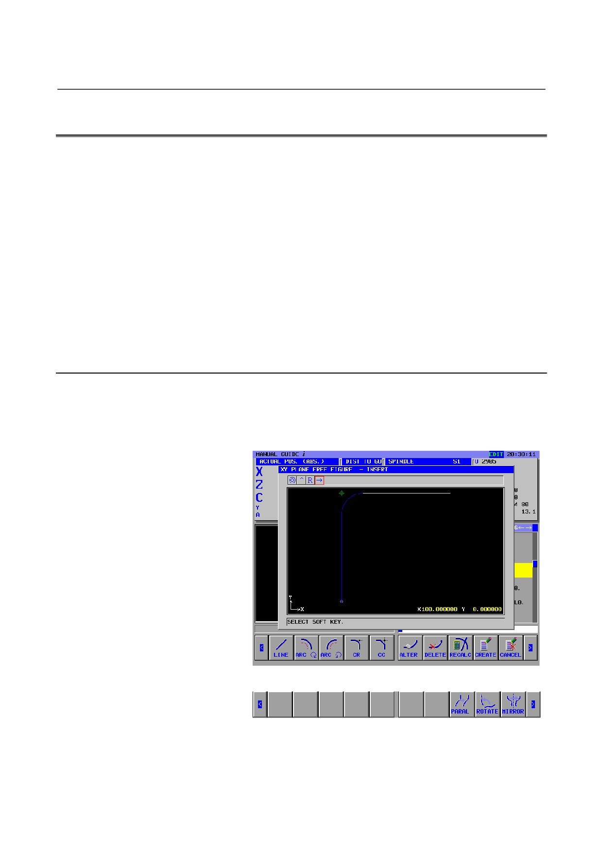
[PARAL], [ROTATE], or [MIRROR] soft key displayed when the [>]
soft key is pressed on the arbitrary figure editing screen.
<1> The following arbitrary figure editing screen is displayed:
<2> Pressing the [>] soft key displays the following soft keys for
arbitrary figure copy operation:
- 140 -
B-63874EN/05
OPERATION 5.DETAILED DESCRIPTIONS ABOUT ENTERING ARBITRARY FIGURES
5.6.2
Copy Condition Input Screen
1)
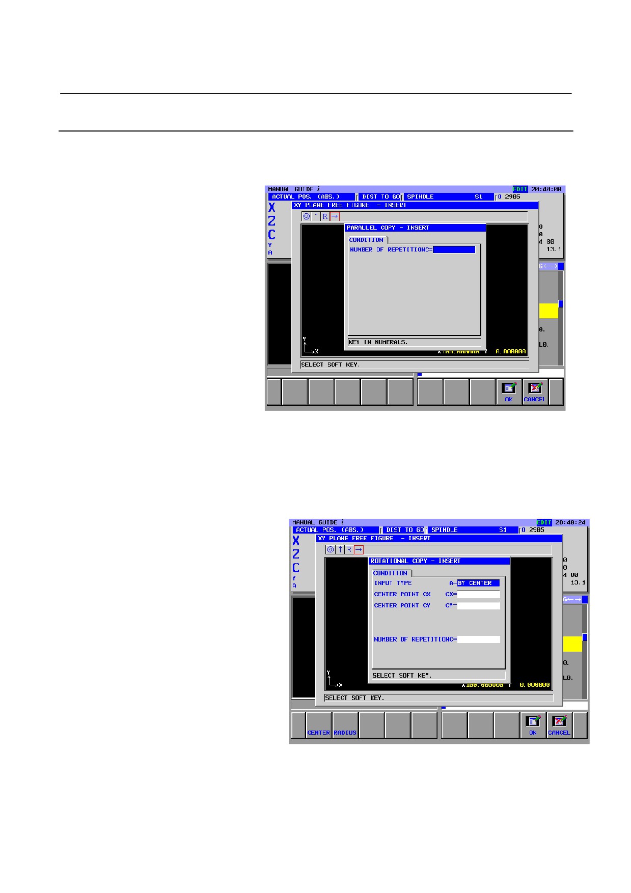
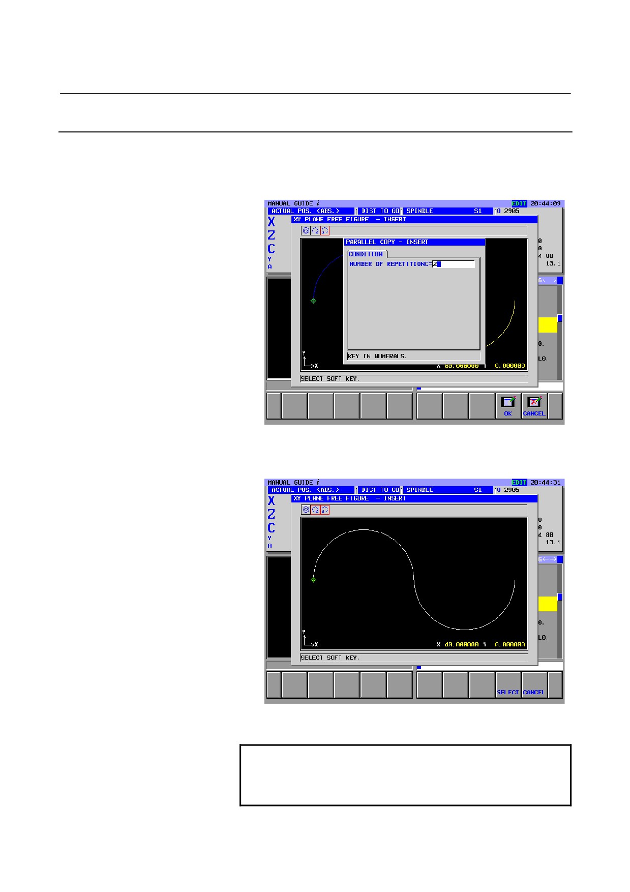
Parallel copy
Parallel copy can be selected by pressing the [PARAL] soft key.
The following screen is displayed:
NUMBER OF REPETITIONC = :
Enter the number of times a selected figure is to be copied.
2)
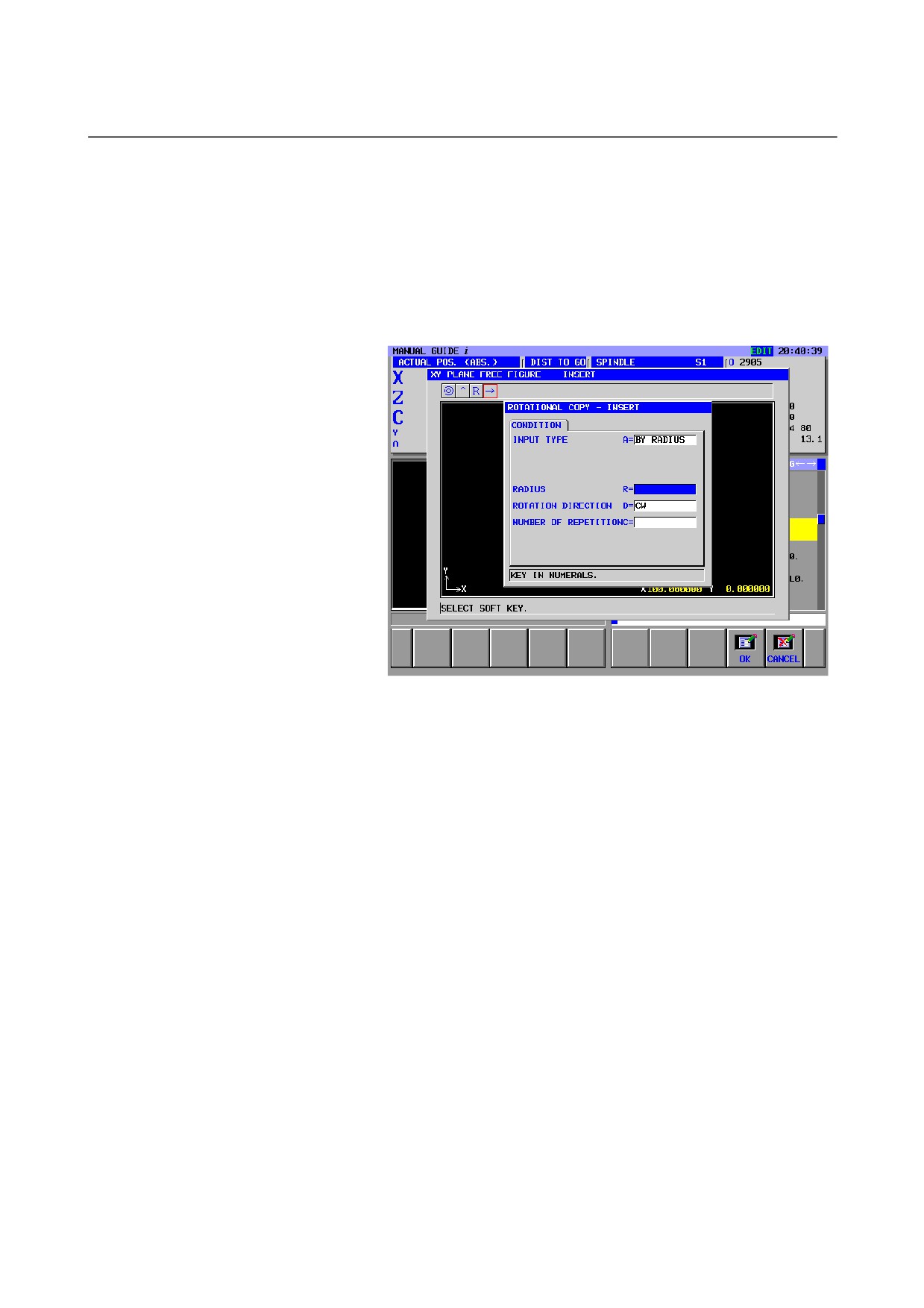
Rotational copy
Rotational copy can be selected by pressing the [ROTATE] soft
key.
The following screen is displayed:
INPUT TYPE :
Select [CENTER] or [RADIUS] to specify the method of
condition input.
- 141 -
5.DETAILED DESCRIPTIONS ABOUT ENTERING ARBITRARY FIGURES OPERATION
B-63874EN/05
CENTER POINT CX, CENTER POINT CY :
Enter the X coordinate and Y coordinate of a rotation center
around which a rotation is made.
NUMBER OF REPETITIONC = :
Enter the number of times a selected figure is to be copied.
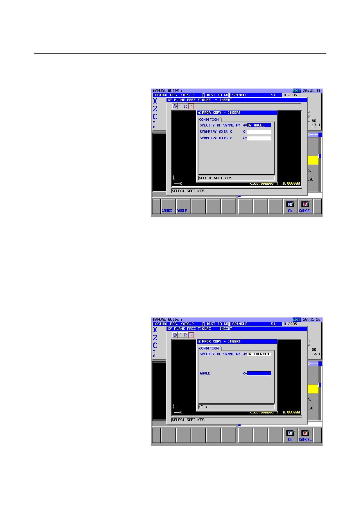
When "BY RADIUS" is selected in "INPUT TYPE", the
following screen is displayed:
RADIUS :
Enter the distance from the start or end point of a selected
figure to the rotation center point.
ROTATION DIRECTION :
Select [CW] or [CCW] to specify the direction of rotation
copy operation.
- 142 -
B-63874EN/05
OPERATION 5.DETAILED DESCRIPTIONS ABOUT ENTERING ARBITRARY FIGURES
3)
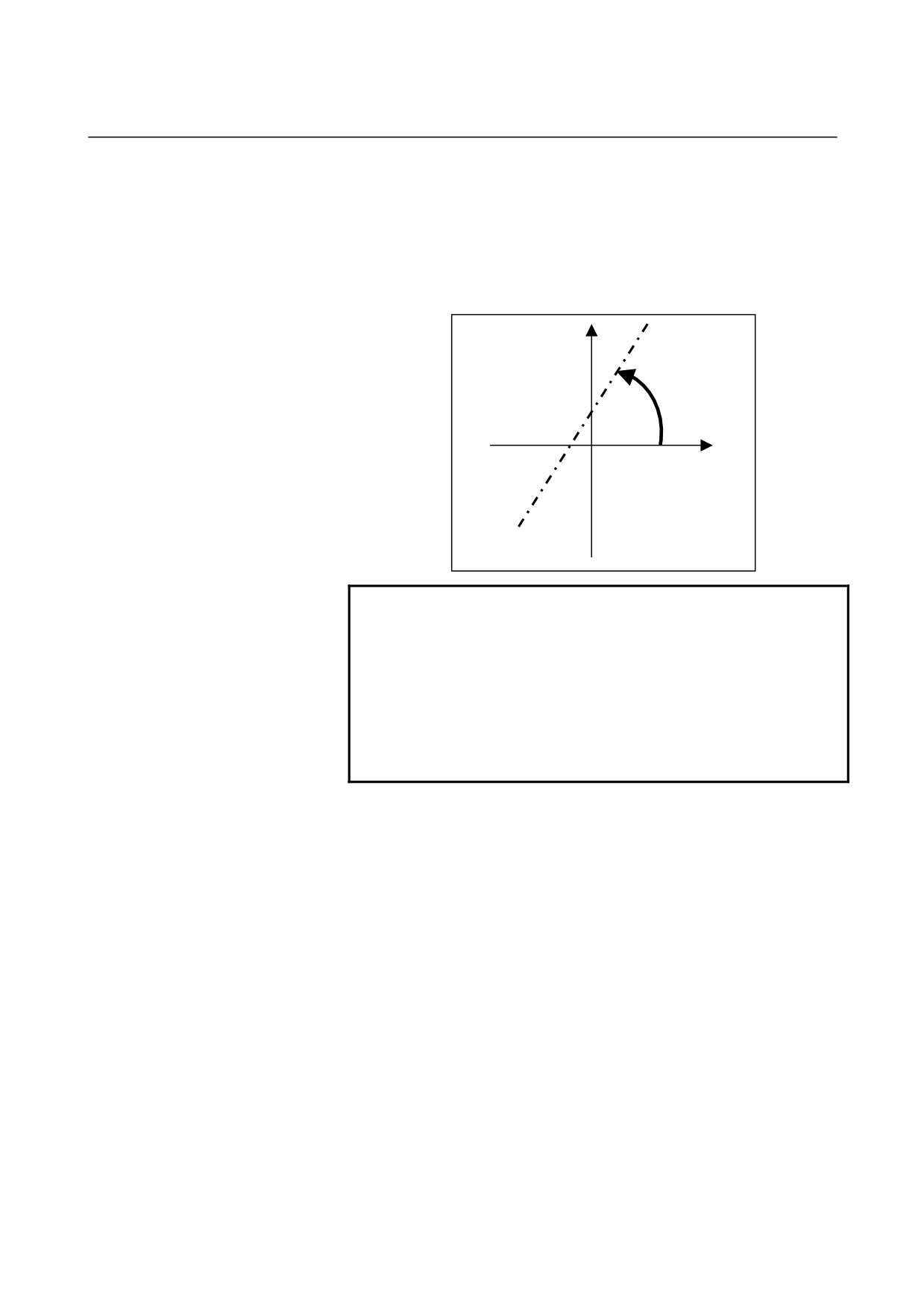
Mirror copy
Mirror copy can be selected by pressing the [MIRROR] soft key.
The following screen is displayed:
SPECIFY OF SYMMETRY :
Use the [COORD] or [ANGLE] soft key to select the
method for specifying a symmetry axis.
SYMMETRY AXIS X, SYMMETRY AXIS Y :
Enter X and Y coordinates through which the symmetry
axis for mirror copying passes. The symmetry axis should
pass through the end point of a specified figure and these X
and Y coordinates.
When "BY ANGLE" is selected in "SPECIFY OF
SYMMETRY", the following screen appears:
- 143 -
5.DETAILED DESCRIPTIONS ABOUT ENTERING ARBITRARY FIGURES OPERATION
B-63874EN/05
ANGLE :
Enter the angle between a symmetry axis used for mirror
copy operation and the horizontal axis. The plus direction
of the horizontal axis represents 0°. Enter a positive value
for an angle made toward the plus vertical axis direction.
Enter a negative value for an angle made toward the minus
vertical axis direction.
+Direction
NOTE
Data entered on the parallel copy input screen,
rotation copy input screen, or mirror copy input
screen is not output to the program.
Each figure entered by a type of copy operation is
automatically expanded as an arbitrary figure
element, so that each figure can be modified.
However, the state before copy operation cannot be
automatically resumed.
- 144 -
B-63874EN/05
OPERATION 5.DETAILED DESCRIPTIONS ABOUT ENTERING ARBITRARY FIGURES
5.6.3
Executing Arbitrary Figure Copy Operation
Use the operation procedure described below.
(Example) Parallel copy
<1> Enter the number of repetition on the copy input screen then
press the [OK] soft key.
<2> The screen for specifying an area of figure used as a copy source
appears. Move the cursor to the icon of the figure element at
the start of the area, then press the [SELECT] soft key.
Pressing the [CANCEL] soft key returns the screen display to the
arbitrary figure editing screen.
NOTE
A selected copy source ranges from the figure
where the cursor is placed when the [SELECT] soft
key is pressed to the last figure.
- 145 -
5.DETAILED DESCRIPTIONS ABOUT ENTERING ARBITRARY FIGURES OPERATION
B-63874EN/05
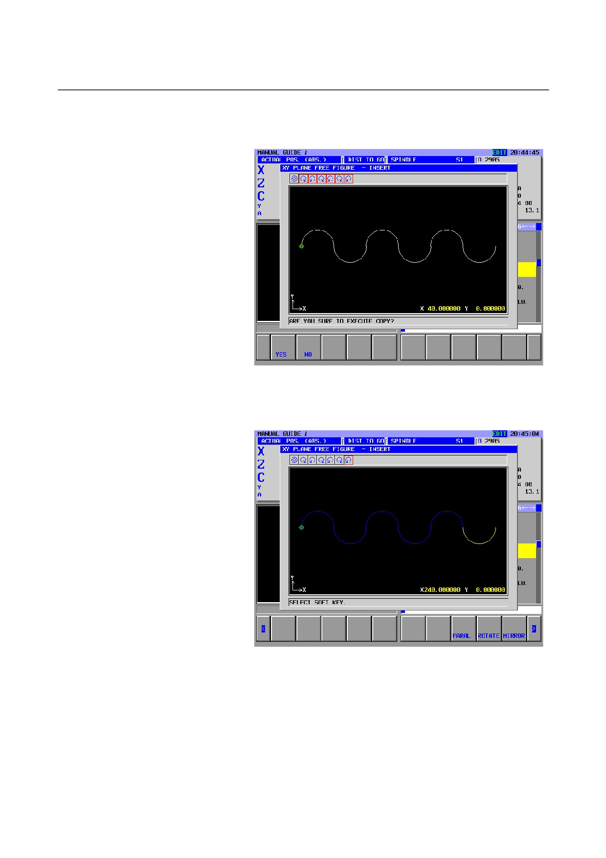
<3> At this time, the graphic window displays a figure produced by
executing copy operations repeatedly. A figure produced by
copying is inserted after the selected copy source.
Pressing the
[NO] soft key returns the screen display to the
previous step.
<4> Pressing [YES] at the end fixes a figure produced by repeated
copy operations.
- 146 -

B-63874EN/05
OPERATION 5.DETAILED DESCRIPTIONS ABOUT ENTERING ARBITRARY FIGURES
5.6.4
Figure after Arbitrary Figure Copy Execution
When the screen used for entering a copied figure is opened by
selecting [ALTER], the set input items differ from those set for the
figure before being copied, as described below.
For a straight line:
Only the input items "LINE DIRECTION" and "END POINT"
are set.
For an arc:
Only the input items "RADIUS" and "END POINT " are set.
If a copy source figure includes a corner R and chamfer, the corner R
and chamfer are an arc and straight line, respectively, in a figure
produced by copying.
This is because parallel, rotation, or mirror copy operation is
performed according to the end point information of the copy source
figure. So, information such as "NEXT CONNECTION" set for a
copy source figure is not reflected in a figure produced by copying.
5.6.5
Notes on Arbitrary Figure Copy Operation
•
A warning is output if the result of expansion based on an
attempt for copy operation exceeds the maximum allowable
number of blocks.
•
The end point of the last selected copy source figure needs to be
fixed.
•
The element immediately before a selected copy source figure
must not be a corner R or chamfer. Moreover, the starting
element and ending element of a selected copy source figure
must not be a corner R and chamfer.
- 147 -
6.OPERATIONS IN THE MEM MODE OPERATION
B-63874EN/05
6
OPERATIONS IN THE MEM MODE
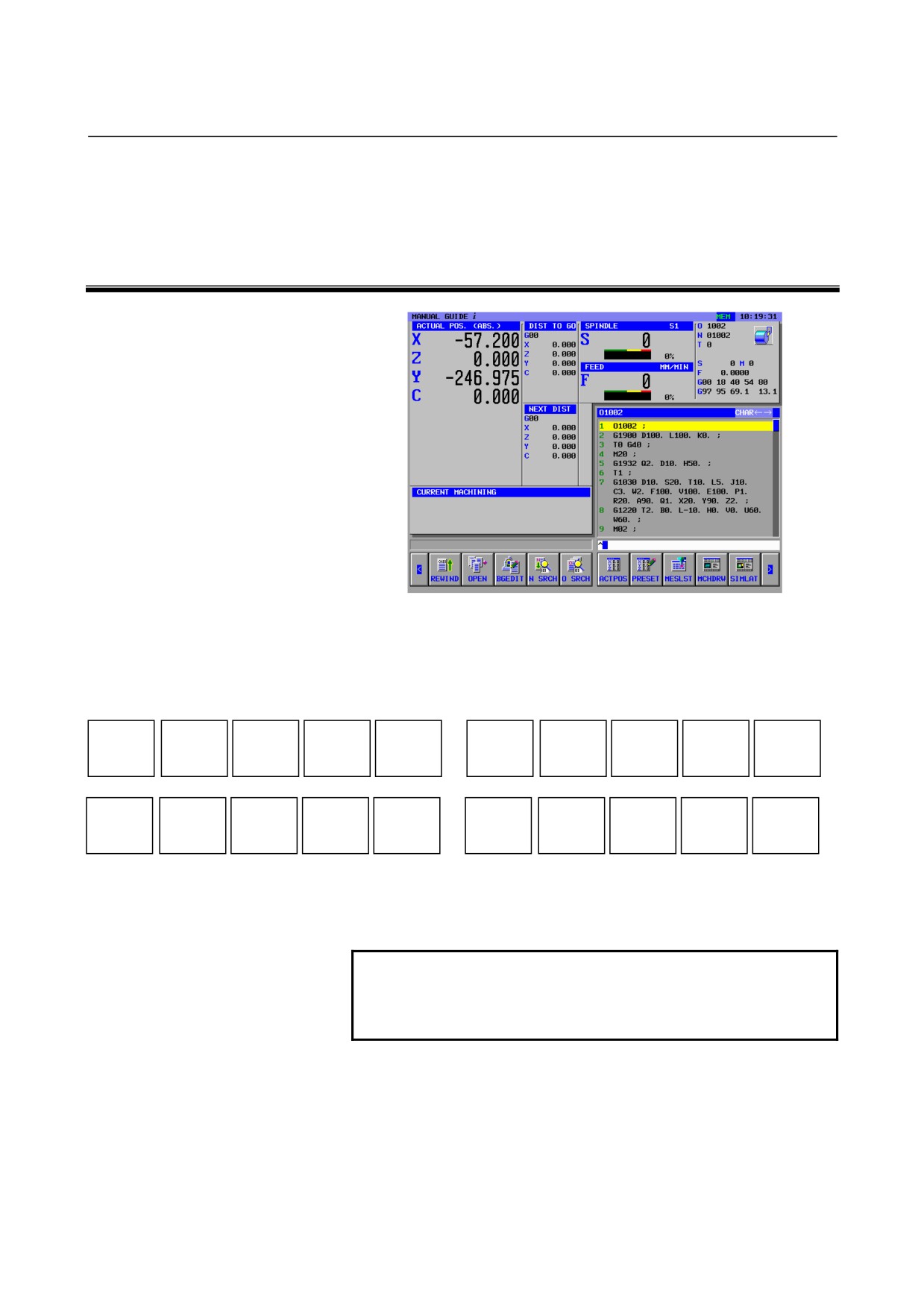
When the MEM mode is selected with the machine operator's panel,
the soft keys shown below appear on the screen of MANUAL GUIDE
i. Pressing the leftmost soft key [<] or the rightmost soft key [>]
changes the page of the soft key display to the second page.
REWIND
O LIST
BGEDIT
N SRCH
O SRCH
ACTPOS
PRESET
MESLST
MCHDRW
SIMLAT
NC CNV
P TYPE
Q TYPE
WRK CO
T-OFS
SETING
(Note)
(Note)
For [SETING], [WRK CO], and [T-OFS], see Chapter 10, "SETTING
DATA," in Part II.
NOTE
When the optional function of PROGRAM
RE-START, the soft-key of [P TYPE] and [Q TYPE]
are displayed on the screen.
- 148 -
B-63874EN/05
OPERATION
6.OPERATIONS IN THE MEM MODE
6.1
REWINDING A MACHINING PROGRAM
REWIND
O LIST
BGEDIT
N SRCH
O SRCH
ACTPOS
PRESET
MESLST
MCHDRW
SIMLAT
By pressing [REWIND], you can return to the beginning of a selected
program.
6.2
EDITING WITH THE MACHINING PROGRAM LIST
REWIND
O LIST
BGEDIT
N SRCH
O SRCH
ACTPOS
PRESET
MESLST
MCHDRW
SIMLAT
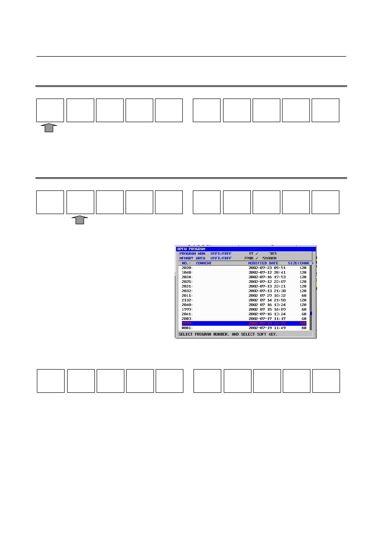
By pressing
[O-LIST], a window showing a list of registered
machining programs is displayed.
The following soft keys appear, allowing you to select machining
programs.
SEARCH
SRTORD
OPEN
CANCEL
[SEARCH] : A window for searching programs appears. Enter the
number of the program you want to search for with
numeric keys, then press
[SEARCH]. The search
window can be closed using [CANCEL].
[OPEN]
: After performing the above search operation or moving
the cursor to a desired program number by using the
cursor keys ↑ and ↓, press [OPEN]. Then the program
is selected.
[CANCEL] : Close the list window.
[SRTORD] : This soft key switches the sort order for displaying
programs between ascending order and descending
order.
- 149 -
6.OPERATIONS IN THE MEM MODE OPERATION
B-63874EN/05
6.3
SEARHING FOR A SEQUENCE NUMBER IN A PROGRAM
REWIND
O LIST
BGEDIT
N SRCH
O SRCH
ACTPOS
PRESET
MESLST
MCHDRW
SIMLAT
When you enter the sequence number you want to search for by using
numeric keys then press [N SRCH], you can search for the block
having the sequence number.
When you press [N SRCH] without entering any data, the sequence
number (N) is searched for sequentially.
If the sequence number is not found, a warning is displayed. It can be
released by pressing a key.
6.4
SELECTING A PROGRAM FOR MACHINING OPERATION
REWIND
O LIST
BGEDIT
N SRCH
O SRCH
ACTPOS
PRESET
MESLST
MCHDRW
SIMLAT
When you enter the program number you want to select by using
numeric keys then press [O SRCH], the program with the program
number is selected and displayed in the program window.
By pressing [O SRCH] without entering any key, the next program is
selected.
NOTE
If the parameter No.3202#3 is set to “1”, pressing
[O SRCH] without entering any data, the next
program is not selected.
6.5
CHANGING THE CURRENT POSITION DISPLAY
REWIND
O LIST
BGEDIT
N SRCH
O SRCH
ACTPOS
PRESET
MESLST
MCHDRW
SIMLAT
By pressing [ACTPOS], the current position display in the status
display window in the upper part of the screen changes in the
sequence "ACTUAL POS.
(ABS)"
→ "ACTUAL POS.
(RELATIVE)" → "ACTUAL POS. (MACHINE)"
If the manual handle interrupt option function is attached, the position
display changes in the sequence "ACTUAL POS.
(ABS)"
→
"ACTUAL POS. (RELATIVE)" → "ACTUAL POS. (MACHINE)"
→ “HANDLE INTER.(INPUT)” → “HANDLE INTER.(OUTPUT)”
- 150 -
B-63874EN/05
OPERATION
6.OPERATIONS IN THE MEM MODE
6.6
PRESETTING RELATIVE COORDINATES
REWIND
O LIST
BGEDIT
N SRCH
O SRCH
ACTPOS
PRESET
MESLST
MCHDRW
SIMLAT
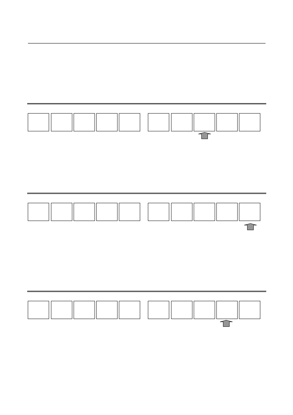
By pressing
[PRESET], a relative coordinates presetting window
appears, allowing you to preset relative coordinates.
When the relative coordinates presetting window is displayed, the
following soft keys are displayed:
ORIGIN
ALL 0
ACTPOS
ALTER
CANCEL
[ORIGIN]
: Set the axis selected with the cursor keys to "0." At this
time, no relative coordinates are preset.
[ALL 0]
: Set all axes to "0." At this time, no relative coordinates
are preset.
Remark) You can set a desired coordinate value for an axis
selected by the cursor by entering the value you want
to preset by using numeric keys then pressing the
INPUT key. At this time, as described above, the
relative coordinates are not yet preset.
[ACTPOS] : Change the current position display in the status display
window in the upper part of the screen in the sequence
"ACTUAL POS.
(ABS)"
→ "ACTUAL POS.
(RELATIVE)" → "ACTUAL POS. (MACHINE)."
If the manual handle interrupt option function is
attached, the position display changes in the sequence
"ACTUAL POS.
(ABS)"
→ "ACTUAL POS.
(RELATIVE)" → "ACTUAL POS. (MACHINE)" →
“HANDLE INTER.(INPUT)”
→
“HANDLE
INTER.(OUTPUT)”
- 151 -
6.OPERATIONS IN THE MEM MODE OPERATION
B-63874EN/05
[ALTER]
: Preset the relative coordinates to coordinate values set
by the above operation. This soft key also closes the
relative coordinates presetting window.
[CANCEL] : Cancel presetting of coordinates and just close the
window.
6.7
DISPLAYING MEASUREMENT RESULTS
REWIND
O LIST
BGEDIT
N SRCH
O SRCH
ACTPOS
PRESET
MESLST
MCHDRW
SIMLAT
By pressing [MESLST], a window showing a list of measurement
results can be displayed. For details of this window, see "MANUAL
GUIDE i Operator’s Manual (Set-up Guidance Function)" or the
manual made by machine tool builder.
6.8
DISPLAYING THE MACHINING SIMULATION WINDOW
REWIND
O LIST
BGEDIT
N SRCH
O SRCH
ACTPOS
PRESET
MESLST
MCHDRW
SIMLAT
By pressing
[SIMLAT], a machining simulation window can be
displayed. For machining simulation, see Chapter 9, "OPERATIONS
IN MACHINING SIMULATION," in Part II.
Press [GRPOFF] to close the machining simulation window.
6.9
DISPLAYING THE DRAWING-DURING-MACHINING
WINDOW
REWIND
O LIST
BGEDIT
N SRCH
O SRCH
ACTPOS
PRESET
MESLST
MCHDRW
SIMLAT
By pressing [MCHDRW], the drawing-during-machining window can
be displayed. For details of drawing during machining, see II.9,
"OPERATIONS IN MACHINING SIMULATION".
Press [GRPOFF] to close the drawing-during-machining window.
- 152 -
B-63874EN/05
OPERATION
6.OPERATIONS IN THE MEM MODE
6.10 BG EDITING
REWIND
O LIST
BGEDIT
N SRCH
O SRCH
ACTPOS
PRESET
MESLST
MCHDRW
SIMLAT
By pressing [BGEDIT], the background editing function can be used.
For details of the background editing function, see II.11,
"OPERATIONS IN BACKGROUND EDITING".
6.11 NC PROGRAM CONVERSION
NC CNV
WK SET
T-OFS
SETING
By pressing [NC CNV], the NC program conversion function can be
used. For details of the NC program conversion function, see II.12,
"OPERATIONS WITH THE NC PROGRAM CONVERSION
FUNCTION".
- 153 -
6.OPERATIONS IN THE MEM MODE OPERATION
B-63874EN/05
6.12 NEXT-BLOCK DISPLAY FUNCTION
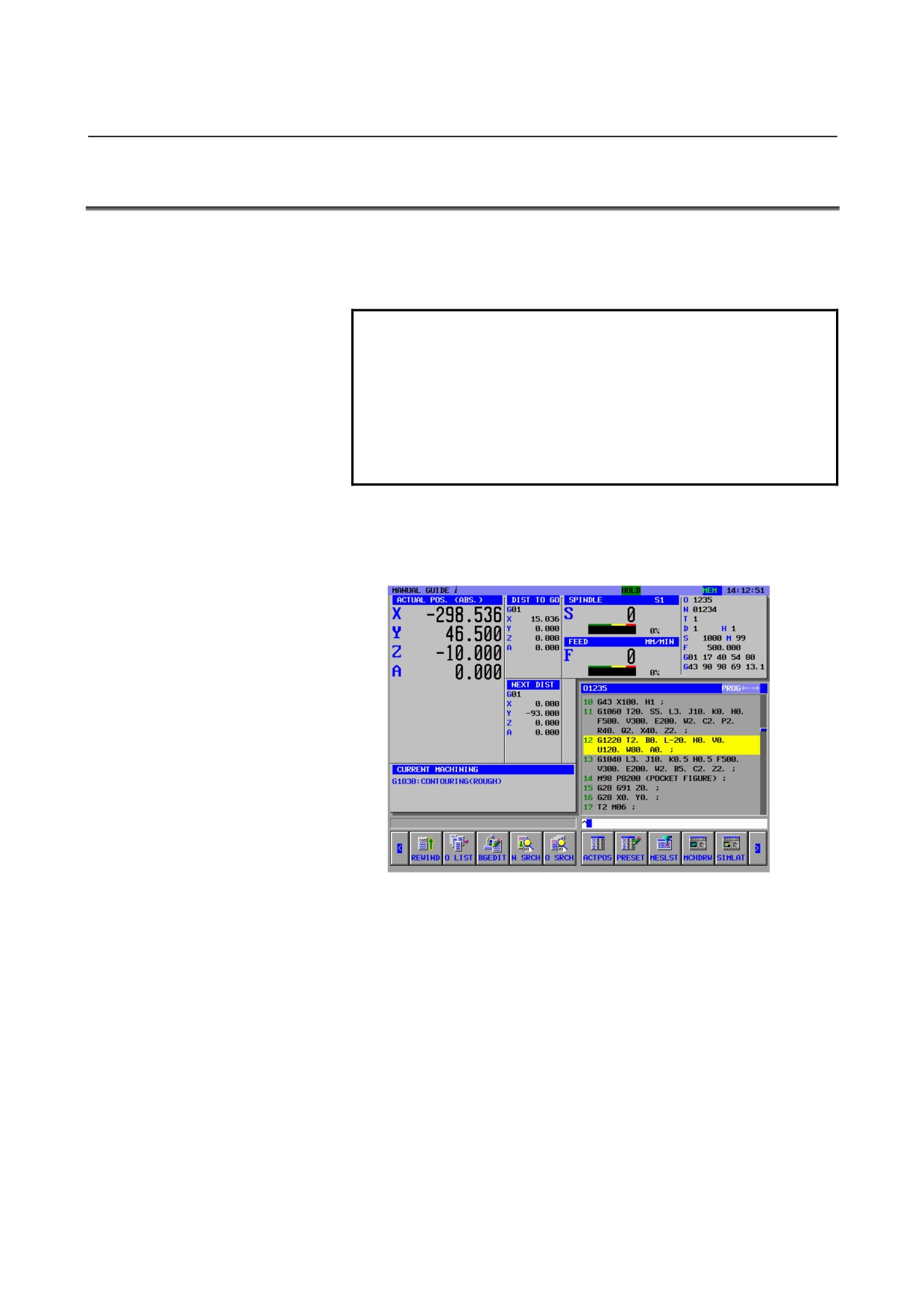
During simulation execution or operation in the MEM mode or MDI
mode, the travel distance data of the block to be executed next is
displayed.
NOTE
1 During actual machining, the travel distance of the
actually executed block is displayed in the “DIST
TO GO” columns, but during machining simulation,
0 value is displayed always in those columns.
2 In order to display the travel distance data of the
block to be executed next during single block
operation, set the parameter No.3106#2 to “1”.
•
In case of machining simulation nor path drawing during actual
machining is not executed
The travel distance data of the next block is automatically
displayed.
- 154 -
B-63874EN/05
OPERATION
6.OPERATIONS IN THE MEM MODE
•
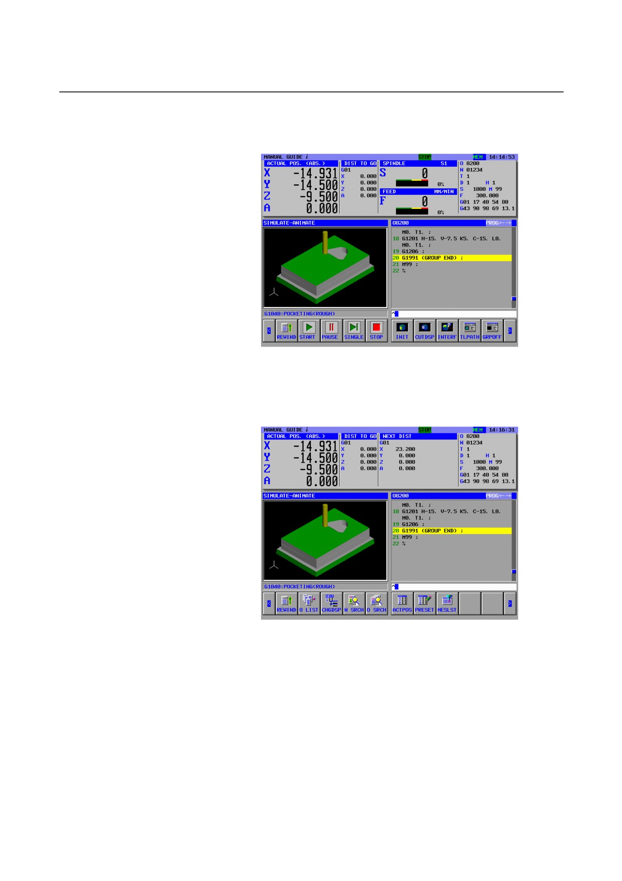
In case of machining simulation or path drawing during actual
machining is executed
Usually, the travel distance of the next block is not displayed.
Pressing
[CHGDSP] erases the display of spindle and actual
feedrate information and displays the travel distance data of the
next block. Pressing [CHGDSP] again returns the screen to the
display of spindle and actual feedrate information.
- 155 -
6.OPERATIONS IN THE MEM MODE OPERATION
B-63874EN/05
6.13 PROGRAM RESTART FUNCTION
When a tool is broken, or machining is to be restarted after holidays,
for example, the block number or sequence number of a block from
which machining is to be restarted can be specified using this function
to enable machining to be restarted from the block. This function can
also be used as a high-speed program check function.
Two methods of restarting are available: P type and Q type.
NOTE
To use this function, the order of movement to a
program restart position needs to be set in
parameter No. 7310.
6.13.1
[P TYPE] Soft-key
NC CNV
P TYPE
Q TYPE
WK SET
T-OFS
SETING
(1) When the program restart signal G006#0 turns to 0 :
Pressing the [P TYPE] soft key has no effect. (Nothing occurs.)
(2) When the program restart signal G006#0 turns to 1 :
<1> Enter one of the following in the key-in buffer:
1.
Sequence number
2.
N sequence number
3.
B block number
4.
Nxxxyyyyy
(xxx: Number of repetition
(3-digit)
yyyyy:Sequence number (5-digit))
5.
xxxyyyyy
(xxx: Number of repetition
(3-digit)
yyyyy:Sequence number (5-digit))
(*) For items 4 or 5, enter an 8-digit number. For sequence
number 3 for two times, for example, enter N00200003.
<2> Press the [P TYPE] soft key.
If a value entered into the key-in buffer satisfies none of the
items 1 through 5, an error is indicated.
<3> The program restart screen is displayed.
NOTE
If [P TYPE] is pressed without performing an
automatic operation even once after the power is
turned on, an emergency stop is reset, or a P/S
alarm (No. 094 to No. 097) is reset, P/S alarm 097
is issued.
- 156 -

B-63874EN/05
OPERATION
6.OPERATIONS IN THE MEM MODE
6.13.2
[Q TYPE] Soft-key
NC CNV
P TYPE
Q TYPE
WK SET
T-OFS
SETING
(1) When the program restart signal G006#0 turns to 0 :
Pressing the [Q TYPE] soft key has no effect. (Nothing occurs.)
(2) When the program restart signal G006#0 turns to 1 :
<1> Enter one of the following in the key-in buffer:
1.
Sequence number
2.
N sequence number
3.
B block number
4.
Nxxxyyyyy
(xxx: Number of repetition
(3-digit)
yyyyy:Sequence number (5-digit))
5.
xxxyyyyy
(xxx: Number of repetition
(3-digit)
yyyyy:Sequence number (5-digit))
(*) For items 4 or 5, enter an 8-digit number. For sequence
number 3 for two times, for example, enter N00200003.
<2> Press the [Q TYPE] soft key.
If a value entered into the key-in buffer satisfies none of the
items 1 through 5, an error is indicated.
<3> The program restart screen is displayed.
- 157 -
7.OPERATIONS IN THE MDI MODE OPERATION
B-63874EN/05
7
OPERATIONS IN THE MDI MODE
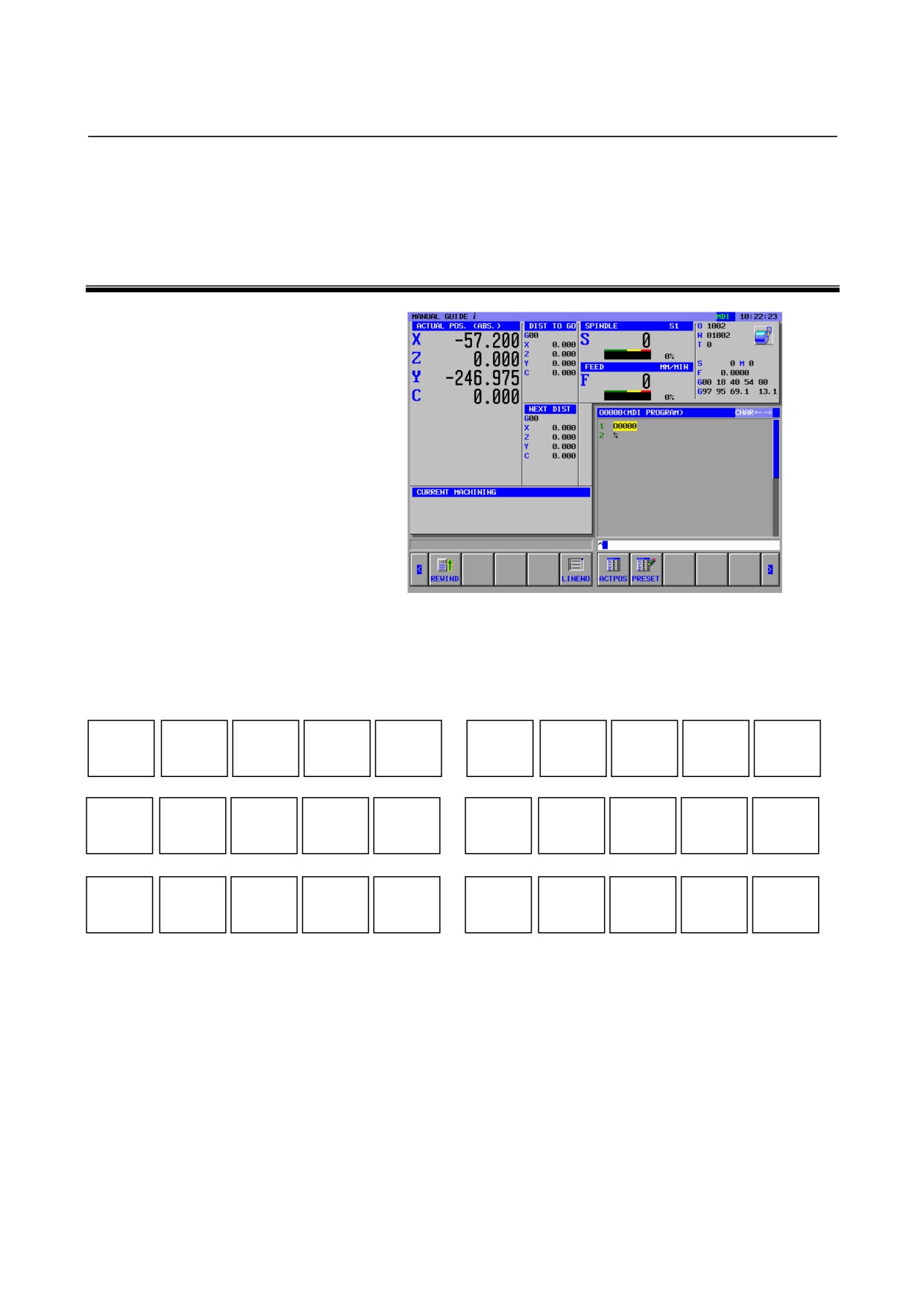
When the MDI mode is selected with the machine operator's panel, the
soft keys shown below appear on the screen of MANUAL GUIDE i.
Pressing the leftmost soft key [<] or the rightmost soft key [>] changes
the page of the soft key display to the second and third pages
sequentially.
REWIND
LINENO
ACTPOS
PRESET
REWIND
SRCH↑
SRCH↓
CHSIZE
COPY
CUT
DELETE
KEYPST
PASTE
WRK CO
OFFSET
SETING
For soft keys [ACTPOS] and [PRESET] on the first page, see the
following sections:
6.5 CHANGING THE CURRENT POSITION DISPLAY
6.6 PRESETTING RELATIVE COORDINATES
- 158 -
B-63874EN/05
OPERATION
7.OPERATIONS IN THE MDI MODE
The soft keys on the second and third pages are used for editing
machining programs entered by MDI. For details on these soft keys,
see the following sections:
3.1 MACHINING PROGRAM WINDOW AND EDITING
3.6 SEARCH (FORWARD AND BACKWARD)
3.7 CUT
3.8 COPY
3.9 PASTE
3.10 DELETION
3.11 KEY-IN PASTE
For [SETING], see Chapter 10, "SETTING DATA," in Part II.
- 159 -
8.OPERATIONS IN THE MANUAL MODE (HANDLE AND JOG) OPERATION B-63874EN/05
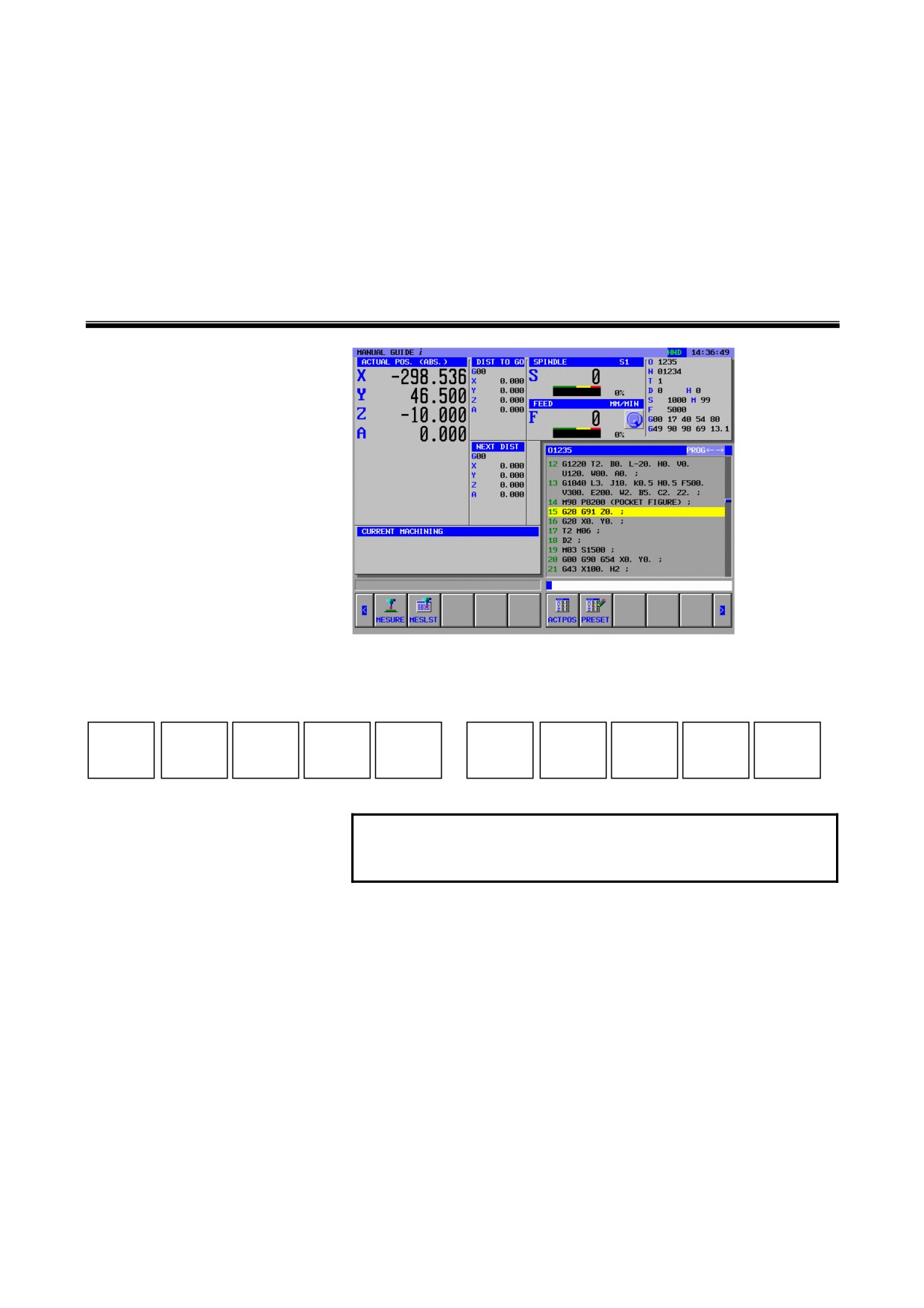
8
OPERATIONS IN THE MANUAL MODE
(HANDLE AND JOG)
When the handle or jog mode is selected with the machine operator's
panel, the following soft keys appear on the screen of MANUAL
GUIDE i:
MESURE
MESLST
ACTPOS
PRESET
SETING
NOTE
1
[MESURE] and [MESLST] are displayed only when
the Set-up guidance optional function is attached.
By pressing [MESURE], a window for set-up guidance functions that
are performed in the manual mode is displayed. By pressing
[MESLST], a window showing a list of measurement results is
displayed. For details of these windows, see "Set-up Guidance" in Part
IV.
For soft keys [ACTPOS] and [PRESET], see the following sections:
6.5 CHANGING THE CURRENT POSITION DISPLAY
6.6 PRESETTING RELATIVE COORDINATES
For [SETING], see Chapter 10, "SETTING DATA," in Part II.
- 160 -
B-63874EN/05
OPERATION
9.MACHINING SIMULATION AND DRAWING DURING MACHINING
9
MACHINING SIMULATION AND
DRAWING DURING MACHINING
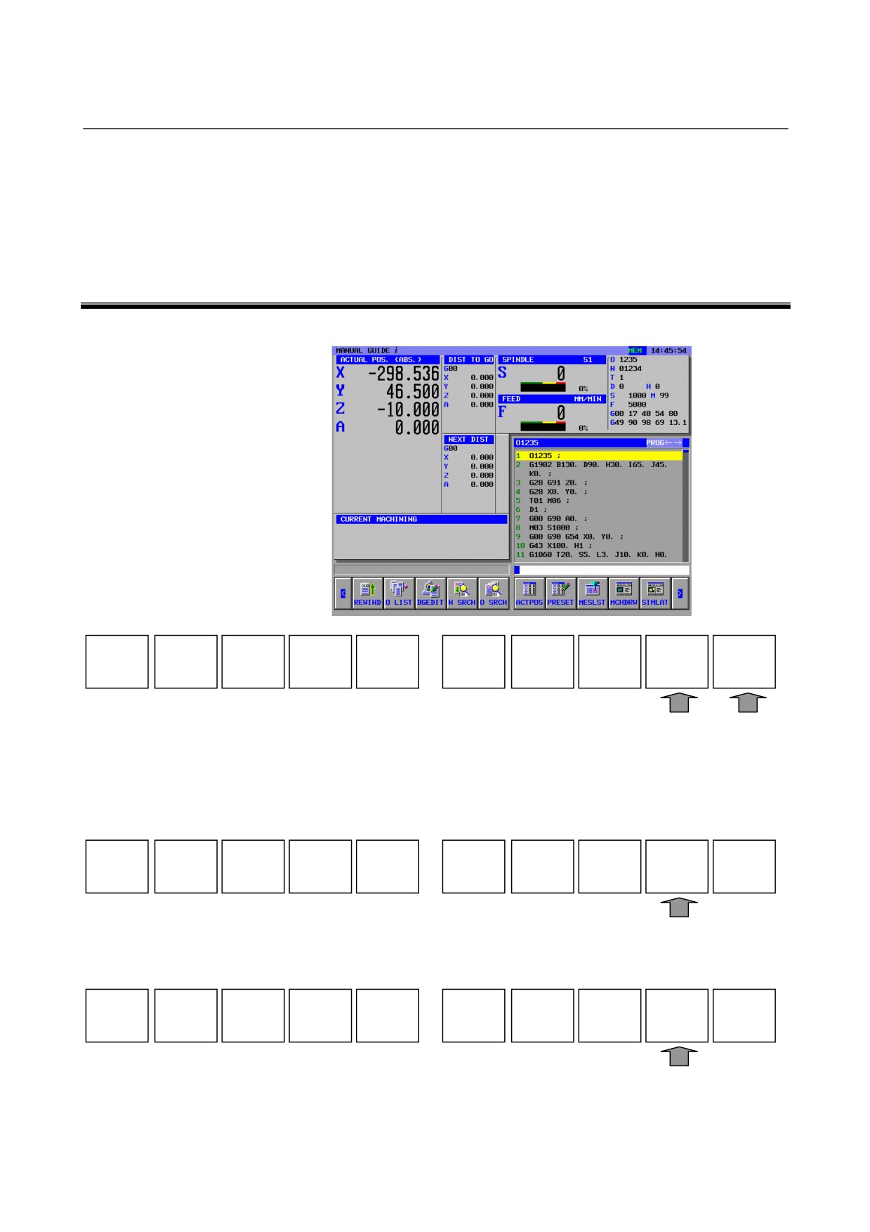
Select the MEM mode on the machine operator's panel.
REWIND
O LIST
BGEDIT
N SRCH
O SRCH
ACTPOS
PRESET
MESLST
MCHDRW
SIMLAT
When you press [MCHDRW], the DRAWING-TOOL PATH screen is
displayed.
When you press
[SIMLAT], the SIMULATE-ANIMATE screen
appears with the following soft keys:
REWIND
START
PROCES
SINGLE
STOP
INIT
CUTDSP
INTERF
TLPATH
GRPOFF
When you press [TLPATH], the SIMULATE-TOOL PATH screen
appears with the following soft keys:
REWIND
START
PROCES
SINGLE
STOP
DISP
NODISP
CLEAR
ANIME
GRPOFF
Pressing
[ANIME] selects the mode for machining simulation
(animated) again.
- 161 -