FANUC MANUAL GUIDE i. OPERATOR’S MANUAL - page 4
4.EDITING CYCLE MACHINING OPERATIONS OPERATION
B-63874EN/05
NOTE
1
Among the data item displayed in the cutting condition
window, there are data should be danger if they are set
automatically such as cutting amount or feedrate. These
data should be entered by an operator always. Other data
are set automatically.
2
Data items displayed in the detail window are usually set
automatically by duplicating the value entered last time. So,
check these automatically set value and modify them if
necessary.
3
Executing cycle machining requires a cycle machining
block and a figure block, which will be explained later.
Once a cycle machining block has been entered, therefore,
be sure to enter a figure block in succession.
4
A data item with an asterisk displayed at its right end has a
default value. You need to enter no data if you accept the
default value.
5
The [CHCURS] soft key is displayed in data entry windows
for cycle machining, figure, and contour programs.
Pressing this soft key can select whether the ← and →
cursor keys are to be used for tab switching or cursor
movement within the entered data. If tab switching is
selected, "Tab ←→" is displayed in the upper right section
of the window. If cursor movement is selected, "Character
←→" is displayed.
- 72 -
B-63874EN/05
OPERATION
4.EDITING CYCLE MACHINING OPERATIONS
4.4
SELECTING FIGURES
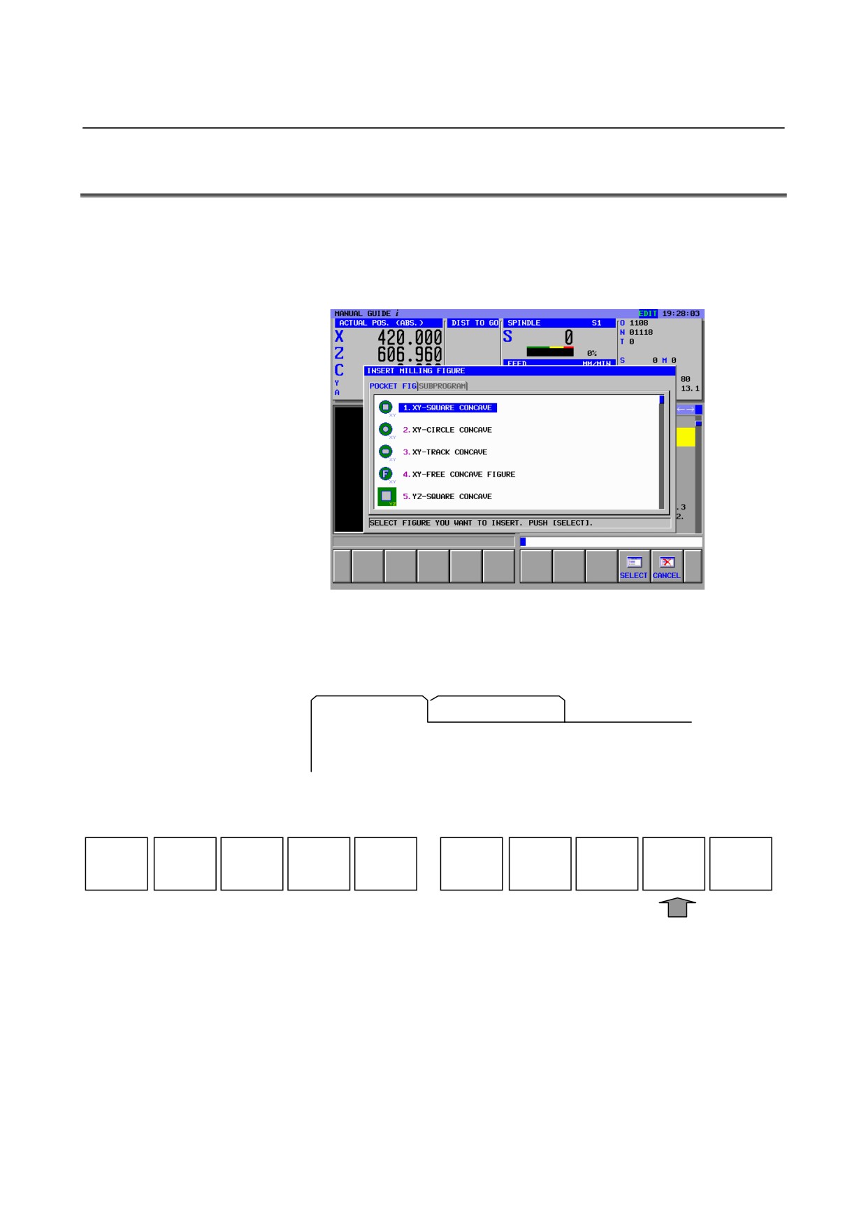
In usual case, entering a cycle motion block displays continuously
the following figure menu exclusively used for the already entered
cycle machining.
(Example of figure menu for pocketing)
The cycle figure menu window is divided into two sections, one
section for selecting figure and the other for subprogram.
(Example of tab for pocketing)
POCKET FIG
SUBPROGRAM
When the figure selection window is selected, the characters of the tab
are displayed in blue. Select a desired figure by moving the cursor
with the cursor keys ↑ and ↓.
SELECT
CANCEL
Pressing [SELECT] displays a data entry window for the selected
figure.
There are 2 types of figures used for cycle machining, fixed form
figure and free form figure.
The former one is predefined figure such as square and circle, and can
be specified by entering minimum data such as side length or circle
radius.
The later one is specified by entering figures by line or arc along the
figures written on a blue print one by one.
- 73 -
4.EDITING CYCLE MACHINING OPERATIONS OPERATION
B-63874EN/05
Pressing the → cursor key displays the menu window of subprogram
and the character in the selected tab is displayed in blue.
If some figure blocks were created as subprogram in advance, the
subprogram number and name are displayed in the subprogram menu,
and suitable subprogram can be selected by placing the cursor on it.
Pressing
[SELECT] create the block for calling the selected
subprogram as “M98 Pxxxx ;” in the actual part program.
It is specified by program number to be displayed in the subprogram
menu or not.
For turning cycle machining figure, the minimum and maximum
program number of the programs should be used as the subprogram
are set in the parameter No.14720
(TFIGSNO) and No.14721
(TFIGENO).
For milling cycle machining figure, the minimum and maximum
program number of the programs should be used as the subprogram
are set in the parameter No.14722
(MFIGSNO) and No.14723
(MFIGENO).
Subprogram whose number is within these range is displayed in the
subprogram menu for turning or milling cycle figure.
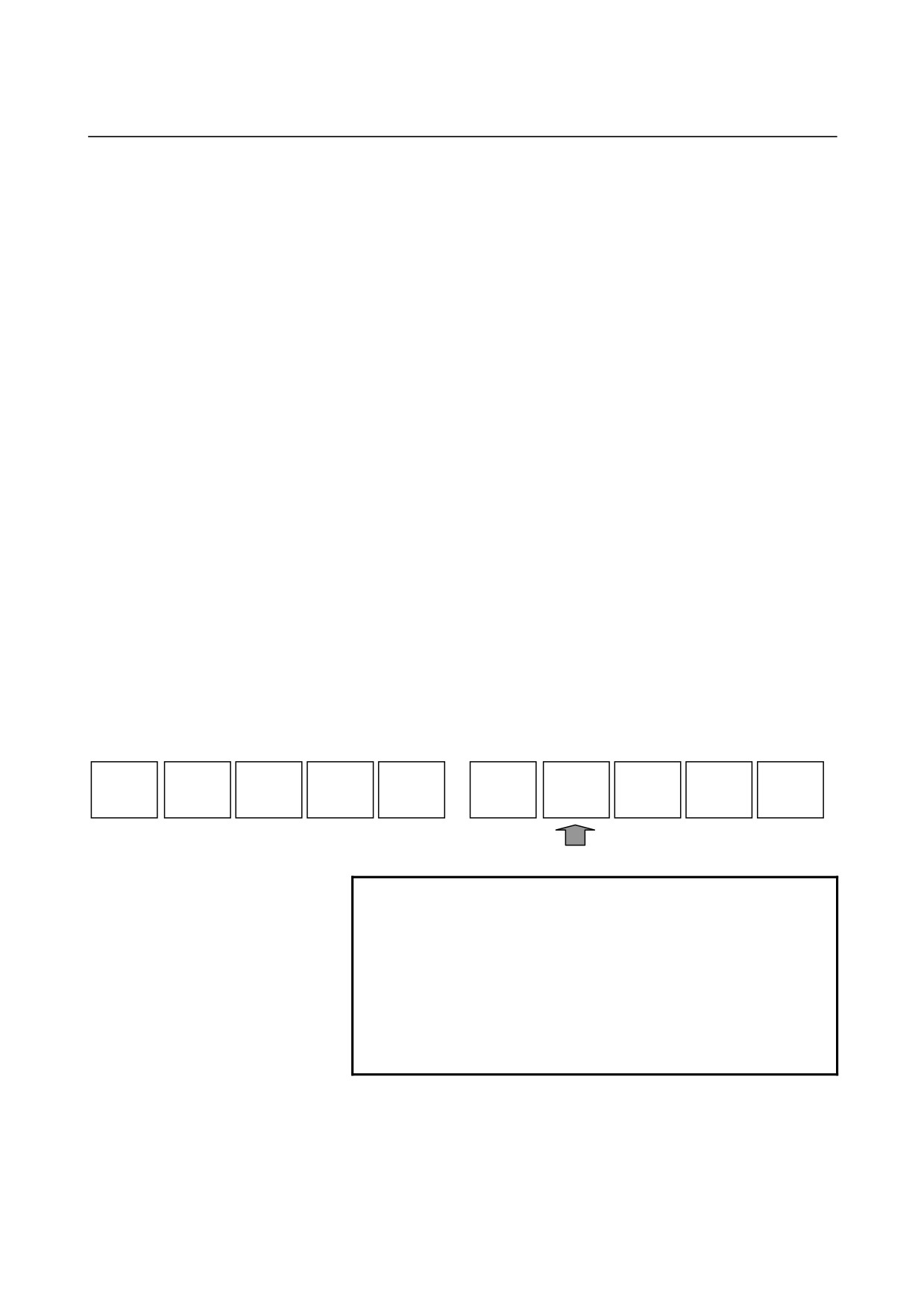
Over 2 figure blocks can be specified continuously for one cycle
machining block. If adding another figure block to the part program in
which cycle machining block and figure block were already inserted,
press [FIGURE] in the soft-keys of program screen and make the
figure menu window display.
But, in this case, all figure menus for all kind of cycle machining are
displayed in one screen. This is different from the figure menu
displayed at the time some cycle machining block is inserted.
START
CYCLE
END
ALTER
FIGURE
M CODE
FIXFRM
NOTE
The scroll bar displayed on the right edge of the
figure menu window indicates the approximate
position of the cursor throughout the figure menu.
If the scroll bar marker is on the middle of the scroll
bar, therefore, it is likely that part of the figure
menu is hidden behind the window. If this is the
case, pressing the ↓ cursor key makes the hidden
part visible.
- 74 -
B-63874EN/05
OPERATION
4.EDITING CYCLE MACHINING OPERATIONS
4.5
ENTERING FIXED FORM FIGURE DATA FOR CYCLE
MACHINING
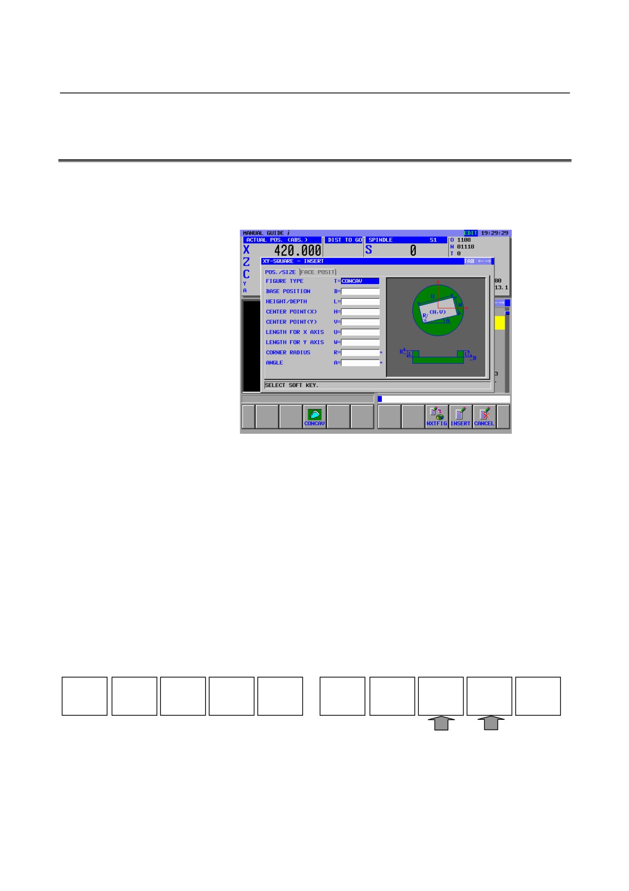
Selecting the fixed form figure displays the data entry window for
cycle machining fixed form data entry window.
(Example of the pocketing fixed form figure)
A data entry window for hole positions, fixed form figures (milling),
turning groove figures, or screw figures (turning) may be extended
over two pages as necessary.
Pressing the ← or → cursor key switches between the two pages. It
also changes the displayed tab.
Pressing the ↑ or ↓ cursor key can place the cursor on a desired data
input item.
There are two types of data input items. One type includes those
entered as numbers, and the other type, those selected from a menu
displayed using a soft key. For the first type, the message "KEY IN
NUMERALS." is displayed in the lower section of the window. For
the second type, the message "SELECT SOFT KEY" is displayed.
Necessary data can be entered by referencing a comment for the data
input item and a guide chart displayed in the window.
The following soft keys are displayed for the fixed form figure data
entry windows.
CONCAV
NXTFIG
INSERT
CANCEL
When the necessary data has been entered, press
[INSERT] or
[NXTFIG], then a block for the related figure block is inserted into a
machining program.
Pressing
[INSERT] returns to the program window. Pressing
[NXTFIG] displays figure selecting menu again.
- 75 -
4.EDITING CYCLE MACHINING OPERATIONS OPERATION
B-63874EN/05
NOTE
1 More than one figure can be entered in succession
for a single cycle machining type.
Cycle machining is executed for each of the
specified figures sequentially.
2 An ordinary ISO code block can be entered
between cycle machining and figure blocks. If this
is done, no machining operation takes place in the
cycle machining block. Instead, the ISO code block
entered before the figure block is executed. Cycle
machining is executed only in the figure block after
the ISO code block has been executed.
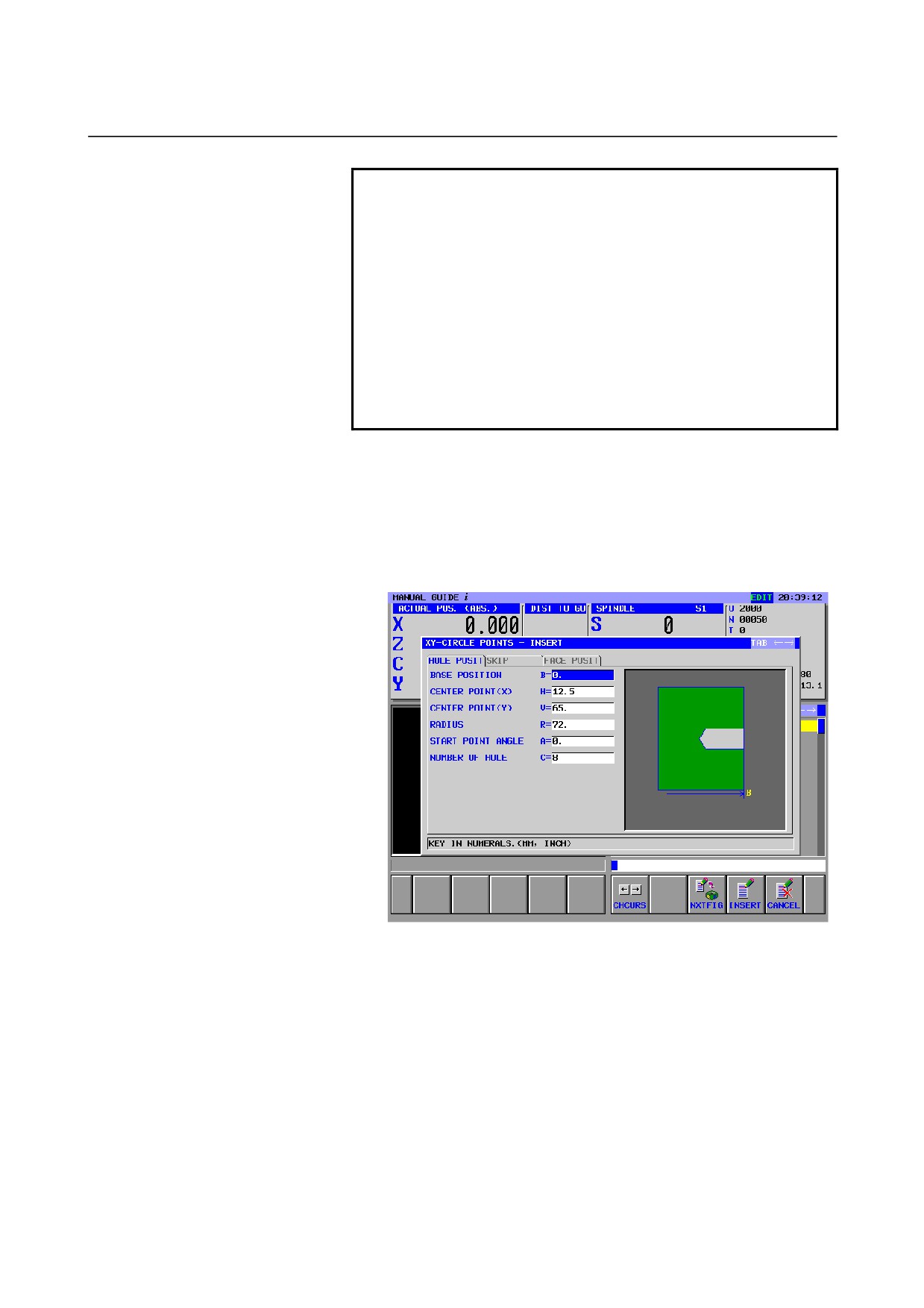
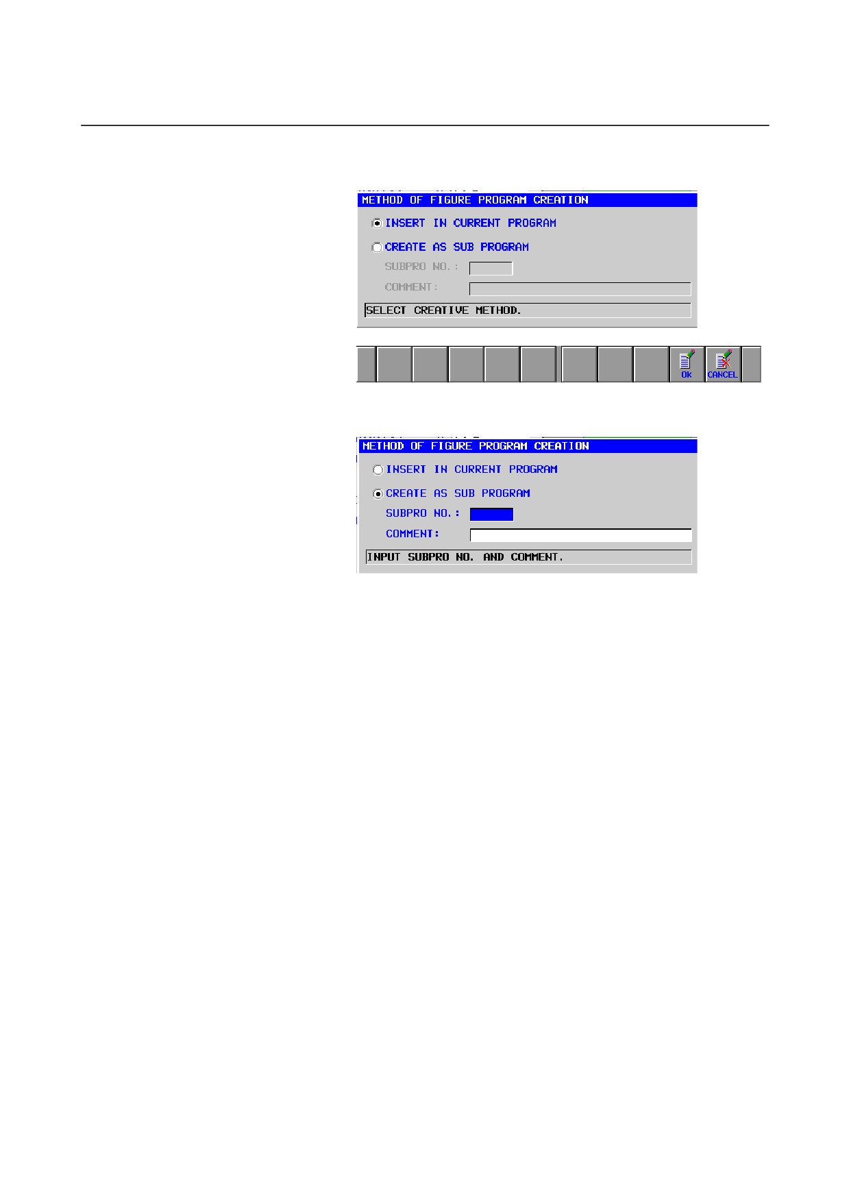
Output as a subprogram
When bit 1 of parameter No. 14851 is set to 1, fixed form figure data
can be output as a subprogram. The operation procedure is described
below.
<1> Press the [INSERT] soft key in the fixed form figure data input
window.
- 76 -
B-63874EN/05
OPERATION
4.EDITING CYCLE MACHINING OPERATIONS
<2> A screen for selecting fixed form figure data as a subprogram is
displayed as shown below.
<3> When creating fixed form figure data as a subprogram, select
"CREATE AS SUB PROGRAM".
<4> If a comment is entered, the entered comment is added to the
M98P**** block of the main program and the subprogram at the
time of program output.
<5> Pressing the [OK] soft key outputs a created fixed form figure
program as a subprogram to the machining program.
- 77 -
4.EDITING CYCLE MACHINING OPERATIONS OPERATION
B-63874EN/05
4.6
ENTERING ARBITRARY FIGURE DATA FOR CYCLE
MACHINING
For cycle machining, an arbitrary figure consisting of circles and
straight lines can be entered by performing automatic calculation on
entered data to obtain the end point of each figure even if no end point
is specified on the drawing.
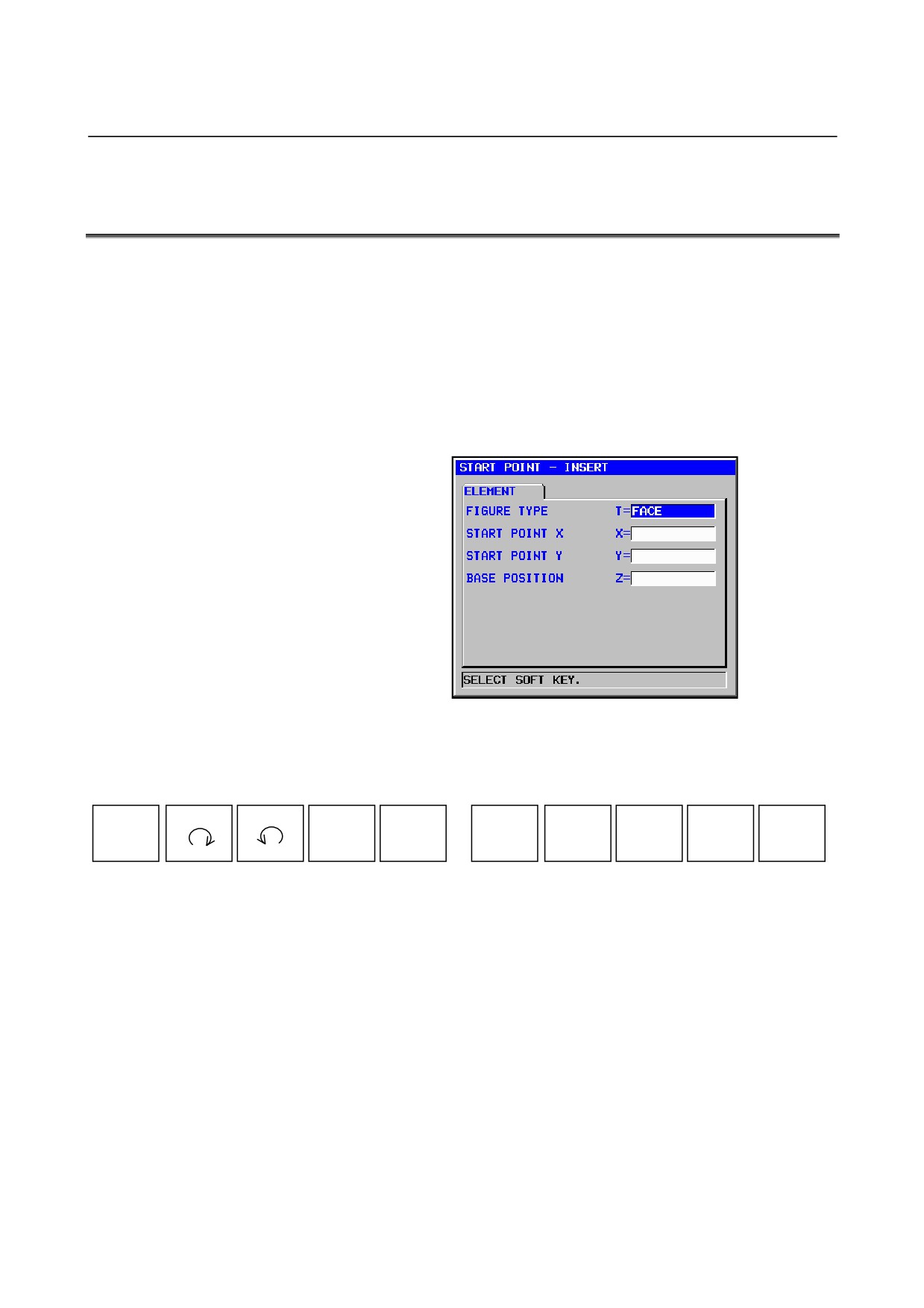
(1) Entering start points
Be sure to enter a start point for the beginning of an arbitrary
figure.
After entering necessary data, press [OK].
(2) Selecting a figure
A menu for figure selection is displayed on soft keys as shown
below. Select whatever is necessary.
LINE
ARC
ARC
CR
CC
ALTER
DELETE
RECALC
CREATE
CANCEL
(3) Entering figure data
When a figure is selected, a figure data entry window appears. In
this window, enter the figure data specified on the drawing.
There are two types of data input items. One type includes those
entered as numbers, and the other type, those selected from a
menu displayed using a soft key. For the first type, the message
"KEY IN NUMERALS." is displayed in the lower section of the
window. For the second type, the message "SELECT SOFT
KEY" is displayed.
After entering the necessary data, press [OK].
- 78 -
B-63874EN/05
OPERATION
4.EDITING CYCLE MACHINING OPERATIONS
NOTE
As figures are entered, they are drawn in the figure
entry window.
In the upper section of the window, symbols for
entered figures are displayed sequentially, starting
at the left. The ← or → cursor key can be used to
select an entered figure; the lines that correspond
to the selected figure will be displayed in yellow.
(4)
Changing figure data
Place the cursor on the figure that contains the figure data you
want to change, and press
[ALTER]. The figure data entry
window appears. In this window, place the cursor on the data
input item you want to change, and enter new data.
If you want to delete data, press the CAN and INPUT keys in the
stated sequence.
Pressing
[OK] closes the figure data entry window. Press
[RECALC] to perform calculation for all entered figures, and
check drawn figures to see if the intended changes have been
made.
(5)
Inserting new figures
After placing the cursor on the figure that precedes immediately
the place where your want to add a figure, select the figure to be
added from the soft key menu.
In the figure data entry window that appears for the new figure,
enter figure data necessary for the figure, and press [OK].
Press [RECALC] to perform calculation for all entered figures,
and check drawn figures to see if the intended additions have
been made.
(6)
Deleting unnecessary figures
After placing the cursor on the figure you want to delete, press
[DELETE].
Press [RECALC] to perform calculation for all entered figures,
and check drawn figures to see if the intended deletions have
been made.
(7)
Changing figures
If you want to change the type of an entered figure, delete it and
enter a new figure.
(8)
Writing entered arbitrary figures to machining programs
After all necessary figures have been entered, they can be written
to machining programs.
There are two methods for writing figures to machining programs.
The first method writes directly to the currently selected
machining program. The second method writes to a newly
created subprogram.
After necessary data has been entered, pressing
[CREATE]
displays a window for selecting one of the creation methods.
- 79 -
4.EDITING CYCLE MACHINING OPERATIONS OPERATION
B-63874EN/05
Select whichever creation method you want, using the ↑ and ↓
cursor keys.
To write to the machining program that has been selected, simply
press [OK].
To create a subprogram, enter a new subprogram number to the
subprogram number item, and then press the INPUT key. You
can enter character strings as a comment if necessary. The
comment is displayed as a program name in the list window.
Pressing [OK] now creates a subprogram and writes figures to
the subprogram.
NOTE
See Chapter 5, "Detailed Descriptions about
Entering Arbitrary Figures," for descriptions about
data for arbitrary figures.
- 80 -
B-63874EN/05
OPERATION
4.EDITING CYCLE MACHINING OPERATIONS
4.7
ENTERING CONTOUR PROGRAMS
It is possible to enter arbitrary figures consisting of circles and straight
lines (contour programs), which are different from cycle machining.
Pressing [G-CONT] displays the same window as for the arbitrary
figure data described earlier. After performing the same operations to
enter figures, write them to the last machining program.
In this case, a G01/G02/G03 program in ISO code format is created.
NOTE
See Chapter 5, "Detailed Descriptions about
Entering Arbitrary Figures," for descriptions about
data entered for contour programs.
(1) Entering insertion character strings
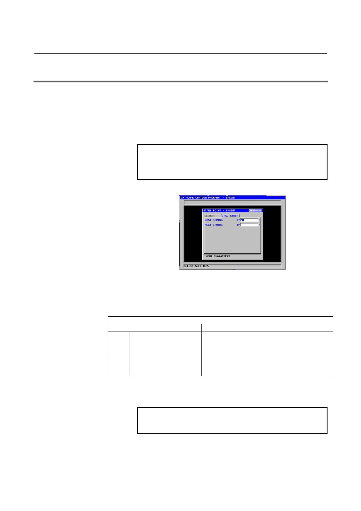
Any character string can be entered to all figure blocks entered
for a contour program.
The "INS. STRIN" tab is added to the entry window for each
figure block of the contour program.
Insertion character string
Data item
Meaning
F*
LAST STRING
Character string (consisting of up to 16 characters)
entered at the beginning (immediately after an
EOB) of each figure block
B*
NEXT STRING
Character string (consisting of up to 16 characters
entered) at the end (immediately before an EOB) of
each figure block
Using "INSERT STRING" can enter G codes and feedrates into figure
blocks.
NOTE
"INSERT STRING" can enter neither a comment
based on a ( ) pair nor an EOB.
(2) Editing figure blocks in contour programs
A figure block entered to a contour program can be edited by
performing figure calculation in the same manner as when it was
entered.
- 81 -
4.EDITING CYCLE MACHINING OPERATIONS OPERATION
B-63874EN/05
For editing figure blocks, entered figure data is written as a
comment to each figure block.
There is a start point G code (G1200, G1300, G1450, G1500, or
G1600) in the first figure block in contour programming. Place
the cursor on the block, and press the [ALTER] soft key.
This operation displays a screen for editing contour programs.
On this screen, perform the same editing operation as for other
arbitrary figures.
- 82 -
B-63874EN/05
OPERATION
4.EDITING CYCLE MACHINING OPERATIONS
4.8
ENTERING THE END COMMAND
START
CYCLE
END
MESCYC
ALTER
FIGURE
M CODE
FIXFRM
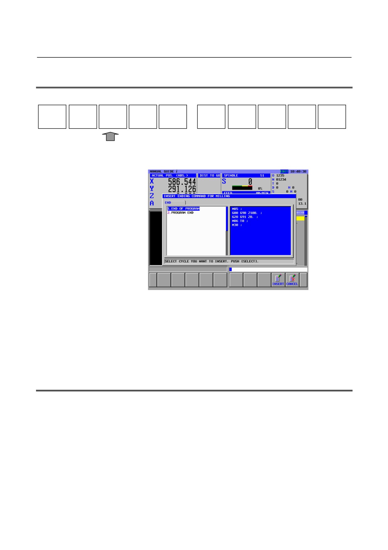
Pressing [END] displays the end command fixed form sentence menu.
Select a fixed form sentence, using the ↑ and ↓ cursor keys.
Pressing [INSERT] inserts the selected fixed form sentence to the
place that follows immediately the current cursor position in the
program.
This operation makes it easy to enter machining program patterns
(fixed form sentences) that are used frequently at machining program
start.
4.9
CHANGING CYCLE MACHINING AND FIGURE DATA
To change the contents of a machining cycle and fixed form figure,
place the cursor on the related block, and press [ALTER].
To change the contents of an arbitrary figure and contour program,
place the cursor at the first of the related blocks, and press [ALTER].
In any case, a data entry window for these items appears. After
making the necessary data changes, press [CREATE] in the same
manner as for new entry. New figures are written to the machining
program.
- 83 -
5.DETAILED DESCRIPTIONS ABOUT ENTERING ARBITRARY FIGURES OPERATION
B-63874EN/05
5
DETAILED DESCRIPTIONS ABOUT
ENTERING ARBITRARY FIGURES
This chapter explains data for arbitrary figures entered with
MANUAL GUIDE i.
NOTE
1
When entering arbitrary figures, enter all the data
for each figure specified on the drawing.
If superfluous data is entered, it will not be used in
figure calculation; only the data necessary for
figure calculation is used.
2
If all the data necessary for figure calculation is
specified on the drawing, entering it enables figure
calculation. If data is insufficient, however, it is
necessary to calculate and enter the necessary
figure data separately.
3
If arbitrary-figure calculation according to MANUAL
GUIDE i produces more than one candidate figure,
the figure that passes the shortest path will be
selected automatically.
In calculating a contact between an arc and straight
line or between two arcs, a figure that links two
figures smoothly is selected automatically.
4
On the program editing screen, after moving the
cursor on the sub program call command (M98
P****) which is composed by the arbitrary figure
blocks, pressing the [INPUT] key displays the
window for editing the arbitrary figures to edit
directly.
5
When positioning the cursor on the block of
subprogram calling in the program-editing screen,
arbitrary figures of the subprogram is drawn on the
graphic window.
- 84 -
B-63874EN/05
OPERATION 5.DETAILED DESCRIPTIONS ABOUT ENTERING ARBITRARY FIGURES
5.1
INCREMENTAL PROGRAMMING
In entering arbitrary figures of element “LINE” or “ARC”, the end
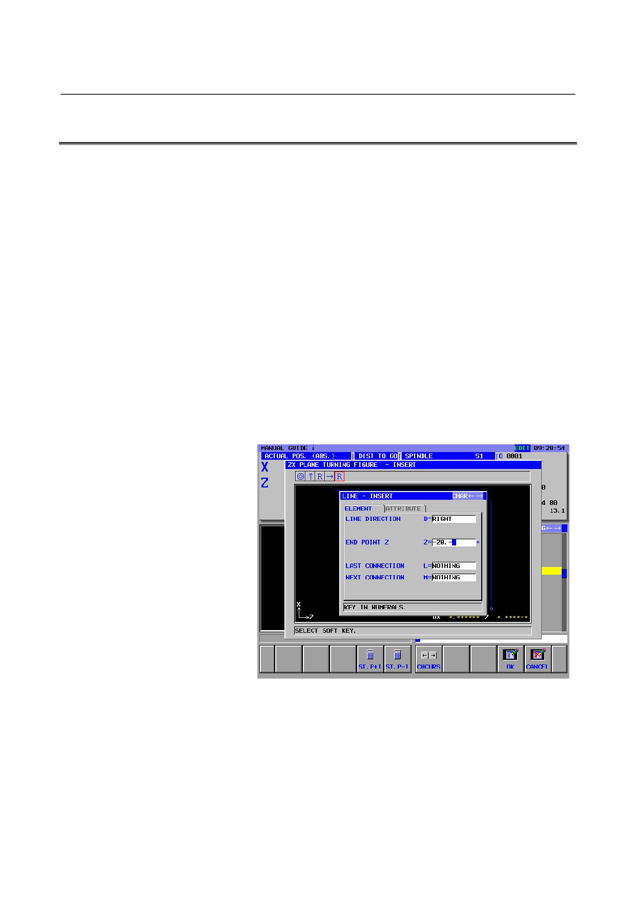
point can be set as an incremental programming.
When positioning the cursor on “END POINT”, the soft key [ST.P+I]
and [ST.P-I] are displayed.
(1) When the operator pushes the soft key [ST.P+I], “END POINT”
is set to
“Start Point of the figure (=End Point of last figure) +”.
And input the increment or decrement in succession. As result of
pushing [INPUT] key, the plus incremental value is set.
(2) When the operator pushes the soft key [ST.P-I], “END POINT”
is set to
“Start Point of the figure (=End Point of last figure) -”.
And input the increment or decrement in succession. As result of
pushing [INPUT] key, the minus incremental value is set.
- 85 -
5.DETAILED DESCRIPTIONS ABOUT ENTERING ARBITRARY FIGURES OPERATION
B-63874EN/05
NOTE
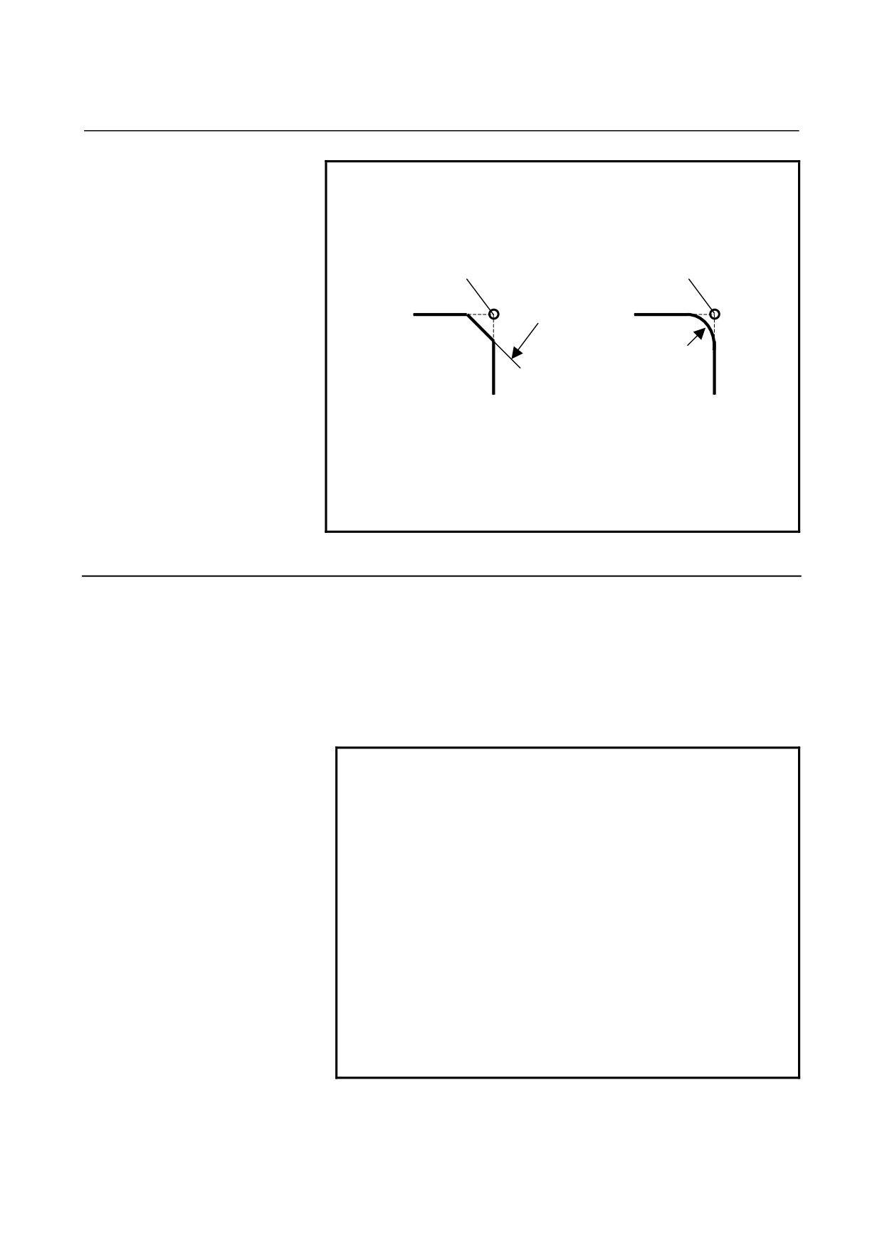
1 If the last figure element is
“CORNER R” or
“CHAMFER”, The point to set as the start point in
this function is as follows.
Start Point
Start Point
C
R
Fig1 Last figure is a chamfer.
Fig2 Last figure is a corner R.
2 If “END POINT” of the last figure is pending, “END
POINT” is not set to the start point by pressing the
software key [ST.P+I] and [ST.P-I]. The warning
message “START POINT IS PENDING.” is
displayed.
5.1.1
Arbitrary Figures for the XY Plane
Arbitrary figures in the XY plane can be used in the following types
of milling.
1. Facing
2. Contouring (Side cutting)
3. Pocketing
4. Grooving
5. Emboss machining
NOTE
1 See Chapter 1, "Milling," in Part III for detailed
descriptions about data to be entered for each type
of cycle machining.
2 When entering an arbitrary figure for pocketing,
make its end point coincide with its start point. To
put another way, combine parts figures with blank
figures in such a way that a closed curve is
created.
Pocketing is carried out in this closed curve.
3 It is possible to specify "PART" and "BLANK" as
"ELEMENT TYPE" for an individual arbitrary figure.
If a pocket is open in part, this "BLANK" can be
used to enter an arbitrary figure resembling a blank
figure for the open portion, thus carrying out
optimum pocketing.
- 86 -
B-63874EN/05
OPERATION 5.DETAILED DESCRIPTIONS ABOUT ENTERING ARBITRARY FIGURES
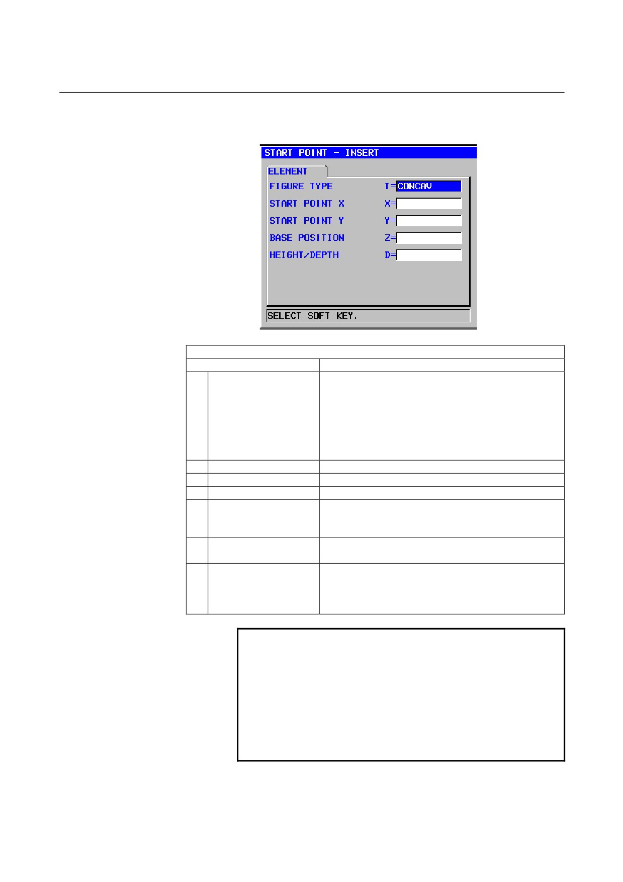
Start point: G1200 (XY plane)
ELEMENT
(INPUT DATA)
(Note 1)
Data item
Meaning
T
FIGURE ATTRIBUTE
[FACE]
: Used as a figure in facing
(Note 2)
[CONVEX] : Used as an outer-perimeter figure in
contouring
[CONCAV] : Used as an inner-perimeter figure in
contouring and emboss machining or a
figure in pocketing
[GROOVE] : Used as a figure in grooving
X
START POINT X
X coordinate of the start point of an arbitrary figure
Y
START POINT Y
Y coordinate of the start point of an arbitrary figure
Z
BASE POSITION
Position of the machining surface of an arbitrary figure
D
HEIGHT/DEPTH
Height or Depth from Base position to cutting surface
Remarks) This item is displayed in Contouring,
Pocketing, Grooving and Emboss machining.
W
GROOVE WIDTH
Groove width (Positive value)
Remarks) This item is displayed in Grooving.
P
FIGURE ATTRIBUTE
[RIGHT] : The right side of an entered figure as cutting
[LEFT]
: The left side of an entered figure as cutting
Remarks) This item is displayed in Open figure of
Contouring.
NOTE
1
‘INPUT DATA’ means the items, which are
displayed on the input data window in editing or
altering.
2 Select, with a figure type for a start point, which
milling operation is to use an arbitrary figure. Data
to be entered for the start point varies depending
on what figure type is selected. For details, see
descriptions about the respective milling types.
- 87 -
5.DETAILED DESCRIPTIONS ABOUT ENTERING ARBITRARY FIGURES OPERATION
B-63874EN/05
ELEMENT
(OUTPUT DATA)
(Note 3)
Data item
Meaning
T
FIGURE ATTRIBUTE
[1] : Used as a figure in facing
[2] : Used as an outer-perimeter figure in contouring
[3] : Used as an inner-perimeter figure in contouring and
emboss machining or a figure in pocketing
[4] : Used as a figure in grooving
(input value)
H
START POINT X
X coordinate of the start point
(input value)
V
START POINT Y
Y coordinate of the start point
(input value)
B
BASE POSITION
Position of the machining surface
(input value)
L
HEIGHT/DEPTH
Height or Depth from Base position to cutting surface
(input value)
Remarks) This item is displayed in Contouring,
Pocketing, Grooving and Emboss machining.
D
GROOVE WIDTH
Groove width (Positive value)
(input value)
Remarks) This item is displayed in Grooving.
P
FIGURE ATTRIBUTE
[1] : The right side of an entered figure as cutting
[2] : The left side of an entered figure as cutting
(input value)
Remarks) This item is displayed in Open figure of
Contouring.
NOTE
3
‘OUTPUT DATA’ means the items, which are
displayed on the program window as creating
program. It can be referenced only for program
display purposes.
- 88 -
B-63874EN/05
OPERATION 5.DETAILED DESCRIPTIONS ABOUT ENTERING ARBITRARY FIGURES
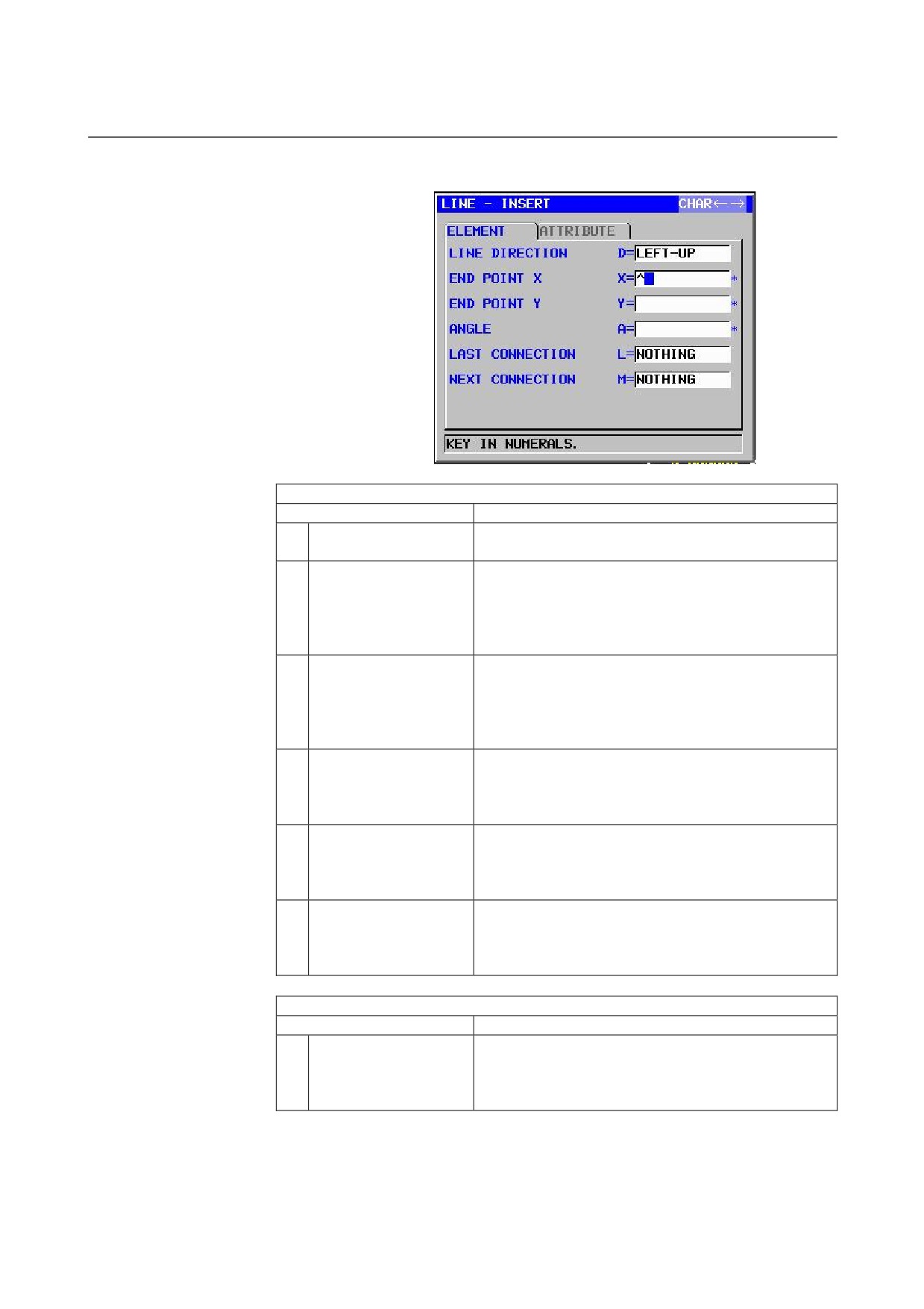
Straight line: G1201 (XY plane)
ELEMENT
(INPUT DATA)
(Note 1)
Data item
Meaning
D
LINE DIRECTION
The direction of a straight line is selected from a menu
indicated on a soft key.
X*
END POINT X
X coordinate of the end point of a straight line
Remarks1) This data may not be displayed depending
on the value entered as the direction of the
straight line.
Remarks2) Incremental programming is possible.
Y*
END POINT Y
Y coordinate of the end point of a straight line
Remarks1) This data may not be displayed depending
on the value entered as the direction of the
straight line.
Remarks2) Incremental programming is possible.
A*
ANGLE
Straight-line angle
Remarks) This data may not be displayed depending
on the value entered as the direction of the
straight line.
L
LAST CONNECTION
[TANGNT] : In contact with the immediately preceding
figure
[NO SET]
: Not in contact with the immediately
preceding figure (initial value)
M
NEXT CONNECTION
[TANGNT] : In contact with the immediately following
figure
[NO SET]
: Not in contact with the immediately
following figure (initial value)
ATTRIBUTE
(INPUT DATA)
(Note 1)
Data item
Meaning
T
ELEMENT TYPE
[PART]
: Cut as parts
[BLANK] : Cut as a blank portion
Remarks) The system sets the last data as an initial
value.
- 89 -
5.DETAILED DESCRIPTIONS ABOUT ENTERING ARBITRARY FIGURES OPERATION
B-63874EN/05
NOTE
1
‘INPUT DATA’ means the items, which are
displayed on the input data window in editing or
altering.
ELEMENT & ATTRIBUTE
(OUTPUT DATA)
(Note 2)
Data item
Meaning
H
END POINT X
X coordinate of the end point of a straight line
(calculation result)
V
END POINT Y
Y coordinate of the end point of a straight line
(calculation result)
K
LINE DIRECTION
The direction of a straight line is selected from a menu
indicated on a soft key.
(input value)
C*
END POINT X
X coordinate of the end point of a straight line
(input value)
D*
END POINT Y
Y coordinate of the end point of a straight line
(input value)
A*
ANGLE
Straight-line angle
(input value)
L
LAST CONNECTION
[1] : In contact with the immediately preceding figure
[0] : Not in contact with the immediately preceding figure
(input value)
M
NEXT CONNECTION
[1] : In contact with the immediately following figure
[0] : Not in contact with the immediately following figure
(input value)
T
ELEMENT TYPE
[1] : Cut as parts
[2] : Cut as a blank portion
(input value)
S
SELECT FIG. INFO.
In the case of plural intersection or contact, the operator
sets a candidate.
(input value)
NOTE
2
‘OUTPUT DATA’ means the items, which are
displayed on the program window as creating
program. It can be referenced only for program
display purposes.
- 90 -
B-63874EN/05
OPERATION 5.DETAILED DESCRIPTIONS ABOUT ENTERING ARBITRARY FIGURES
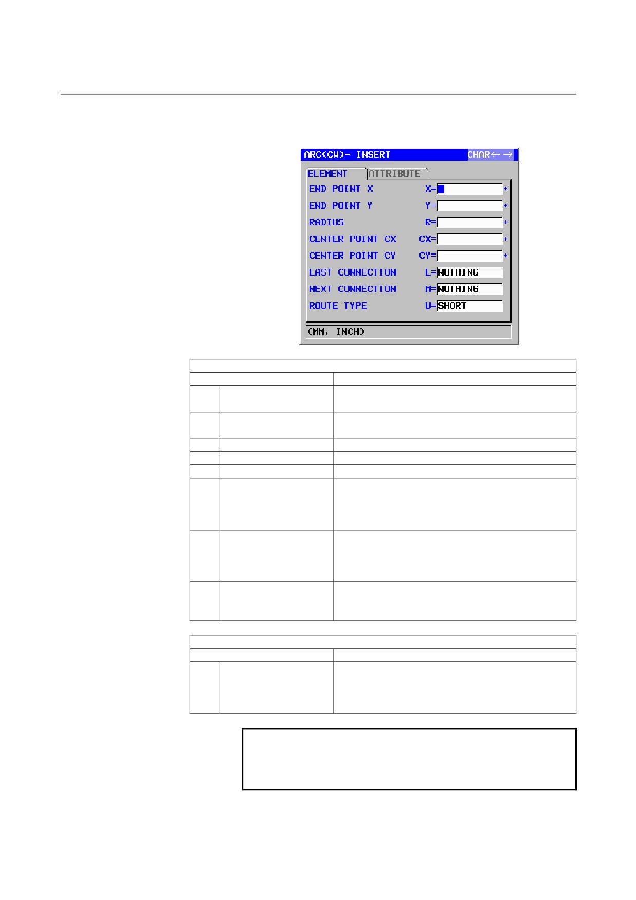
Arc (CW): G1202 (XY plane)
Arc (CCW): G1203 (XY plane)
ELEMENT
(INPUT DATA)
(Note 1)
Data item
Meaning
X*
END POINT X
X coordinate of an arc end point
Remarks) Incremental programming is possible.
Y*
END POINT Y
Y coordinate of an arc end point
Remarks) Incremental programming is possible.
R*
RADIUS
Arc radius
CX*
CENTER POINT CX
X coordinate of an arc center
CY*
CENTER POINT CY
Y coordinate of an arc center
L
LAST CONNECTION
[TANGNT] : In contact with the immediately preceding
figure
[NO SET]
: Not in contact with the immediately
preceding figure (initial value)
M
NEXT CONNECTION
[TANGNT] : In contact with the immediately preceding
figure
[NO SET]
: Not in contact with the immediately
preceding figure (initial value)
U
ROUTE TYPE
[LONG]
: An arc with a short route is made
[SHORT]
: An arc with a long route is made
(initial value)
ATTRIBUTE
(INPUT DATA)
(Note 1)
Data item
Meaning
T
ELEMENT TYPE
[PART]
: Cut as parts
[BLANK] : Cut as a blank portion
Remarks) The system sets the last data as an initial
value.
NOTE
1
‘INPUT DATA’ means the items, which are
displayed on the input data window in editing or
altering.
- 91 -
5.DETAILED DESCRIPTIONS ABOUT ENTERING ARBITRARY FIGURES OPERATION
B-63874EN/05
ELEMENT & ATTRIBUTE
(OUTPUT DATA)
(Note 2)
Data item
Meaning
H
END POINT X
X coordinate of an arc end point (calculation result)
V
END PINT Y
Y coordinate of an arc end point (calculation result)
R
RADIUS
Arc radius (calculation result)
I
CENTER POINT X
X coordinate of an arc center (calculation result)
J
CENTER POINT Y
Y coordinate of an arc center (calculation result)
C*
END POINT X
X coordinate of an arc end point
(input value)
D*
END POINT Y
Y coordinate of an arc end point
(input value)
E*
RADIUS
Arc radius
(input value)
P*
CENTER POINT CX
X coordinate of an arc center
(input value)
Q*
CENTER POINT CY
Y coordinate of an arc center
(input value)
L
LAST CONNECTION
[1] : In contact with the immediately preceding figure
[0] : Not in contact with the immediately preceding figure
(input value)
M
NEXT CONNECTION
[1] : In contact with the immediately preceding figure
[0] : Not in contact with the immediately preceding figure
(input value)
U
ROUTE TYPE
[1] : An arc with a long route is made
[0] : An arc with a short route is made
(input value)
T
ELEMENT TYPE
[1] : Cut as parts
[2] : Cut as a blank portion
(input value)
S
SELECT FIG. INFO.
In the case of plural intersection or contact, the operator
sets a candidate.
(input value)
NOTE
2
‘OUTPUT DATA’ means the items, which are
displayed on the program window as creating
program. It can be referenced only for program
display purposes.
- 92 -
B-63874EN/05
OPERATION 5.DETAILED DESCRIPTIONS ABOUT ENTERING ARBITRARY FIGURES
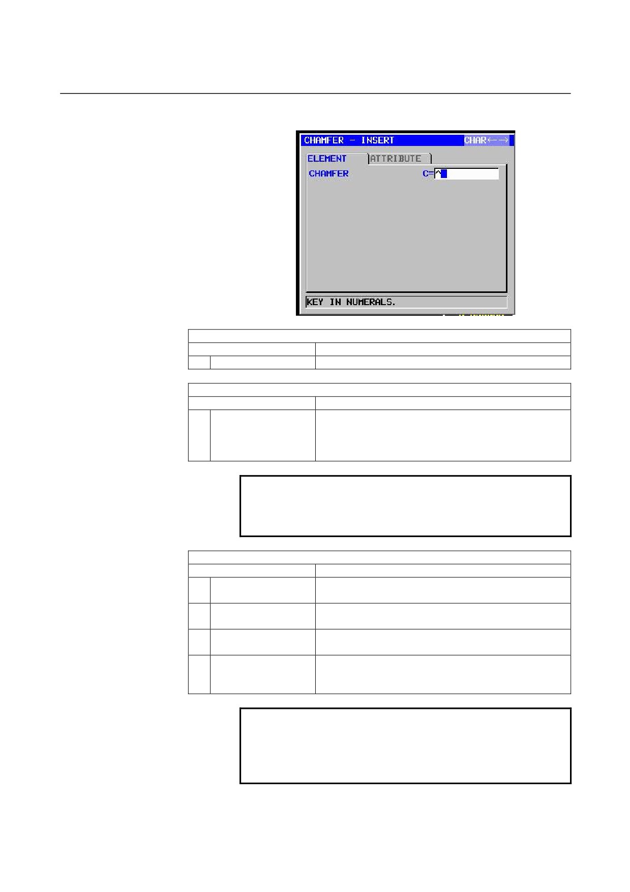
Chamfering: G1204 (XY plane)
ELEMENT
(INPUT DATA)
(Note 1)
Data item
Meaning
C
CHAMFER
Amount of chamfering (radius value, positive value)
ATTRIBUTE
(INPUT DATA)
(Note 1)
Data item
Meaning
T
ELEMENT TYPE
[PART]
: Cut as parts
[BLANK] : Cut as a blank portion
Remarks) The system sets the last data as an initial
value.
NOTE
1
‘INPUT DATA’ means the items, which are
displayed on the input data window in editing or
altering.
ELEMENT & ATTRIBUTE
(OUTPUT DATA)
(Note 2)
Data item
Meaning
H
END POINT X
X coordinate of the end point of a straight line
(calculation result)
V
END POINT Y
Y coordinate of the end point of a straight line
(calculation result)
C
CHAMFER
Amount of chamfering (radius value, positive value)
(input value)
T
ELEMENT TYPE
[1] : Cut as parts
[2] : Cut as a blank portion
(input value)
NOTE
2
‘OUTPUT DATA’ means the items, which are
displayed on the program window as creating
program. It can be referenced only for program
display purposes.
- 93 -
5.DETAILED DESCRIPTIONS ABOUT ENTERING ARBITRARY FIGURES OPERATION
B-63874EN/05
NOTE
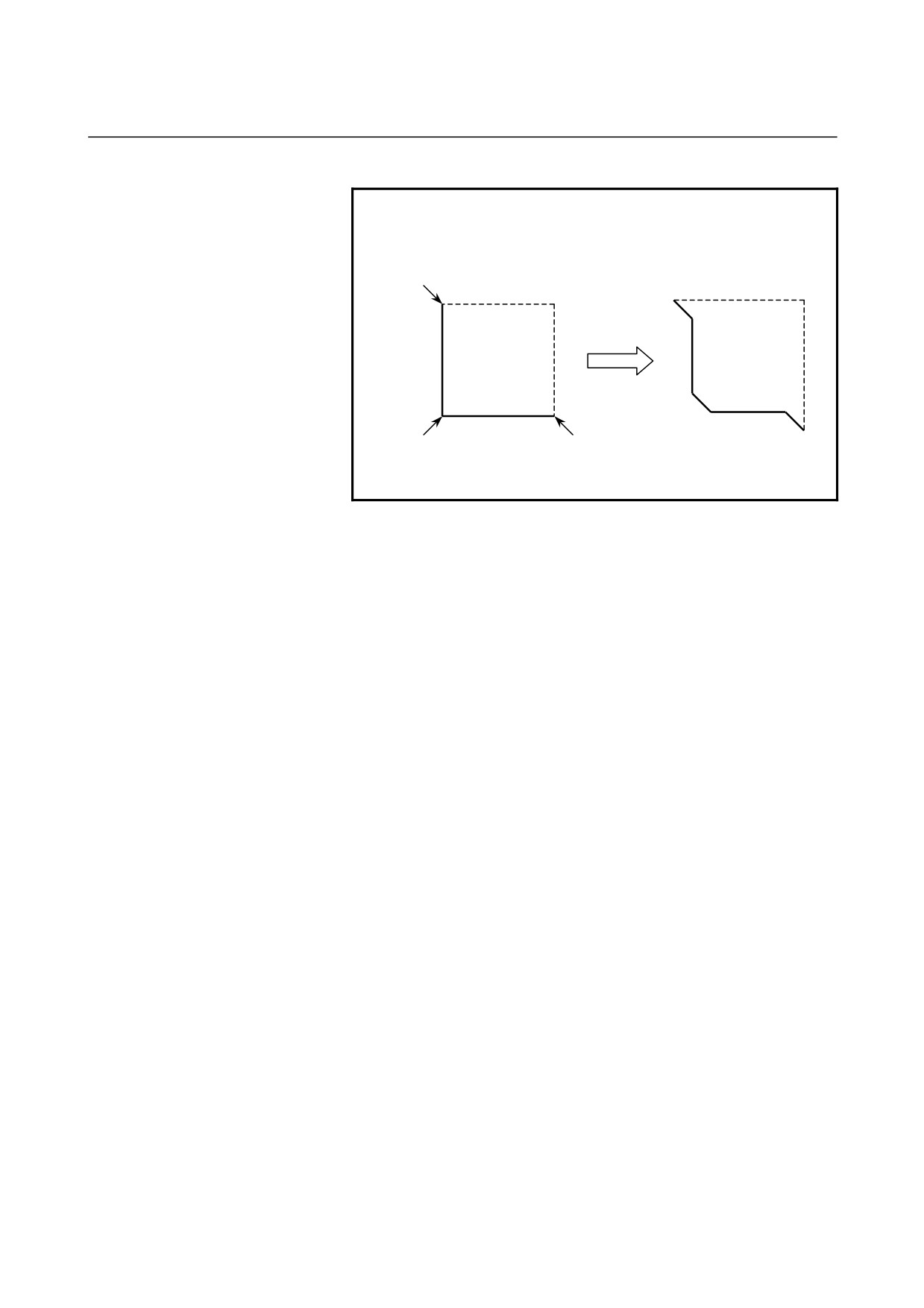
2 By setting the parameter No.14851#0=1, Corner
element between a blank element and a part
element can be created in the opposite direction.
C
C
C
C
C
C
Dotted line : blank element
Normal line : part element
- 94 -
B-63874EN/05
OPERATION 5.DETAILED DESCRIPTIONS ABOUT ENTERING ARBITRARY FIGURES
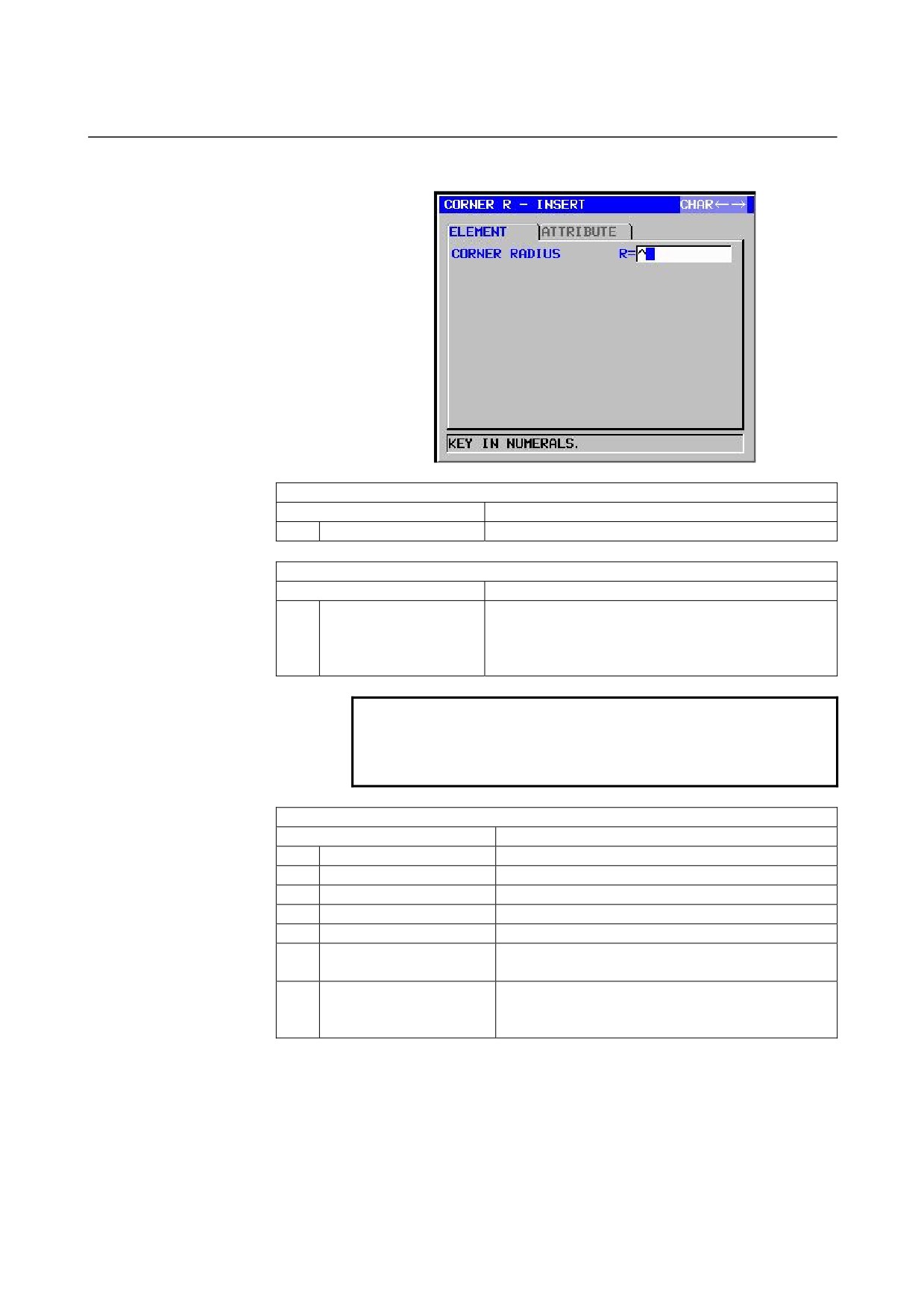
Corner rounding: G1205 (XY plane)
ELEMENT
(INPUT DATA)
(Note 1)
Data item
Meaning
R
CORNER RADIUS
Corner rounding (radius value, positive value)
ATTRIBUTE
(INPUT DATA)
(Note 1)
Data item
Meaning
T
ELEMENT TYPE
[PART]
: Cut as parts
[BLANK] : Cut as a blank portion
Remarks) The system sets the last data as an initial
value.
NOTE
1
‘INPUT DATA’ means the items, which are
displayed on the input data window in editing or
altering.
ELEMENT & ATTRIBUTE
(OUTPUT DATA)
(Note 2)
Data item
Meaning
H
END POINT X
X coordinate of an arc end point (calculation result)
V
END PINT Y
Y coordinate of an arc end point (calculation result)
R
RADIUS
Arc radius
(calculation result)
I
CENTER POINT X
X coordinate of an arc center
(calculation result)
J
CENTER POINT Y
Y coordinate of an arc center
(calculation result)
K
ROTATION DIRECTION
[2] : clockwise
[3] : counterclockwise
T
ELEMENT TYPE
[1] : Cut as parts
[2] : Cut as a blank portion
(input value)
- 95 -

5.DETAILED DESCRIPTIONS ABOUT ENTERING ARBITRARY FIGURES OPERATION
B-63874EN/05
NOTE
2
‘OUTPUT DATA’ means the items, which are
displayed on the program window as creating
program. It can be referenced only for program
display purposes.
3 By setting the parameter No.14851#0=1, Corner
element between a blank element and a part
element can be created in the opposite direction.
End of arbitrary figures: G1206 (XY plane)
This block is output at the end of a series of arbitrary-figure blocks.
NOTE
A series of arbitrary figures must be enclosed
between G1200 (start point) and G1206 (end of
arbitrary figures).
- 96 -
B-63874EN/05
OPERATION 5.DETAILED DESCRIPTIONS ABOUT ENTERING ARBITRARY FIGURES
5.2
ARBITRARY FIGURES FOR THE YZ PLANE
Arbitrary figures in the YZ plane can be used in the following types of
milling.
1. Facing
2. Contouring (Side cutting)
3. Pocketing
4. Grooving
5. Emboss machining
NOTE
See Chapter 1, "Milling," in Part III for detailed
descriptions about data to be entered for each type
of cycle machining.
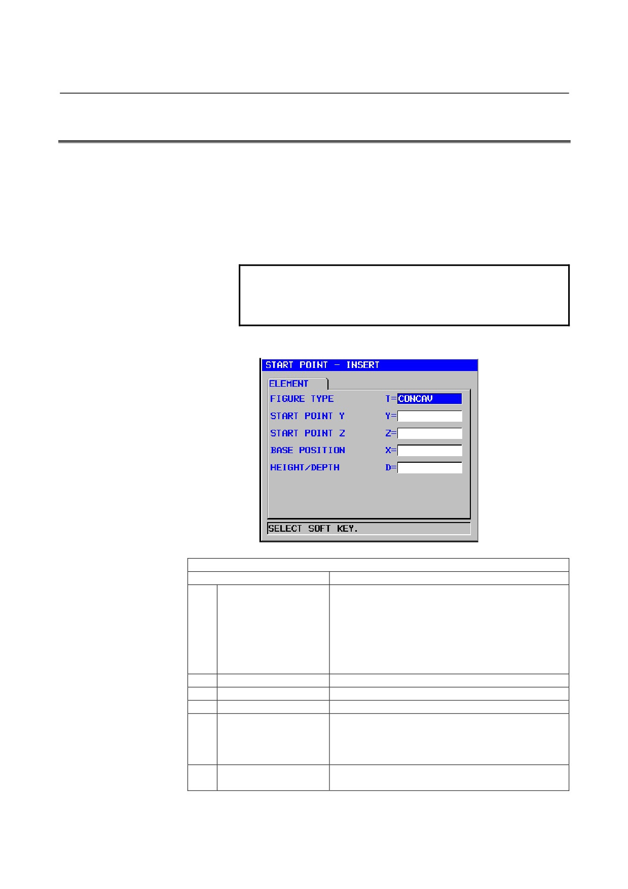
Start point: G1300 (YZ plane)
ELEMENT
(INPUT DATA)
(Note 1)
Data item
Meaning
T
FIGURE ATTRIBUTE
[FACE]
: Used as a figure in facing
(Note 2)
[CONVEX]
: Used as an outer-perimeter figure in
contouring
[CONCAVE] : Used as an inner-perimeter figure in
contouring and emboss machining or a
figure in pocketing
[GROOVE]
: Used as a figure in grooving
Y
START POINT Y
Y coordinate of the start point of an arbitrary figure
Z
START POINT Z
Z coordinate of the start point of an arbitrary figure
X
BASE POSITION
Position of the machining surface of an arbitrary figure
D
HEIGHT/DEPTH
Height or Depth from Base position to cutting surface
Remarks) This item is displayed in Contouring,
Pocketing, Grooving and Emboss
machining.
W
GROOVE WIDTH
Groove width (Positive value)
Remarks) This item is displayed in Grooving.
- 97 -
5.DETAILED DESCRIPTIONS ABOUT ENTERING ARBITRARY FIGURES OPERATION
B-63874EN/05
ELEMENT
(INPUT DATA)
(Note 1)
Data item
Meaning
P
FIGURE ATTRIBUTE
[RIGHT] : The right side of an entered figure as
cutting
[LEFT]
: The left side of an entered figure as cutting
Remarks) This item is displayed in Open figure of
Contouring.
NOTE
1
‘INPUT DATA’ means the items, which are
displayed on the input data window in editing or
altering.
2 Select, with a figure type for a start point, which
milling operation is to use an arbitrary figure. Data
to be entered for the start point varies depending
on what figure type is selected. For details, see
descriptions about the respective milling types.
ELEMENT
(OUTPUT DATA)
(Note 3)
Data item
Meaning
T
FIGURE ATTRIBUTE
[1] : Used as a figure in facing
[2] : Used as an outer-perimeter figure in contouring
[3] : Used as an inner-perimeter figure in contouring and
emboss machining or a figure in pocketing
[4] : Used as a figure in grooving
(input value)
H
START POINT Y
Y coordinate of the start point
(input value)
V
START POINT Z
Z coordinate of the start point
(input value)
B
BASE POSITION
Position of the machining surface
(input value)
L
HEIGHT/DEPTH
Height or Depth from Base position to cutting surface
(input value)
Remarks) This item is displayed in Contouring,
Pocketing, Grooving and Emboss machining.
D
GROOVE WIDTH
Groove width (Positive value)
(input value)
Remarks) This item is displayed in Grooving.
P
FIGURE ATTRIBUTE
[1] : The right side of an entered figure as cutting
[2] : The left side of an entered figure as cutting
Remarks) This item is displayed in Open figure of
Contouring.
(input value)
NOTE
3
‘OUTPUT DATA’ means the items, which are
displayed on the program window as creating
program. It can be referenced only for program
display purposes.
- 98 -
B-63874EN/05
OPERATION 5.DETAILED DESCRIPTIONS ABOUT ENTERING ARBITRARY FIGURES
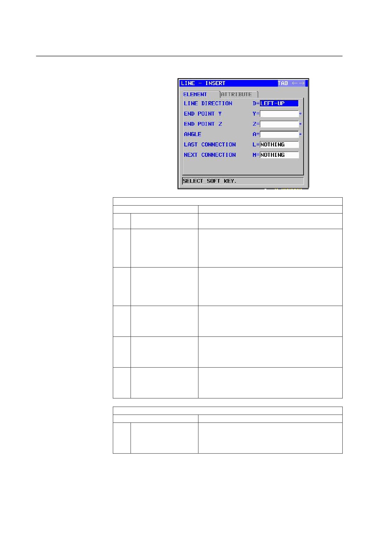
Straight line: G1301 (YZ plane)
ELEMENT
(INPUT DATA)
(Note 1)
Data item
Meaning
D
LINE DIRECTION
The direction of a straight line is selected from a menu
indicated on a soft key.
Y*
END POINT Y
Y coordinate of the end point of a straight line
Remarks1) This data may not be displayed depending
on the value entered as the direction of the
straight line.
Remarks2) Incremental programming is possible.
Z*
END POINT Z
Z coordinate of the end point of a straight line
Remarks1) This data may not be displayed depending
on the value entered as the direction of the
straight line.
Remarks2) Incremental programming is possible.
A*
ANGLE
Straight-line angle
Remarks) This data may not be displayed depending
on the value entered as the direction of the
straight line.
L
LAST CONNECTION
[TANGNT] : In contact with the immediately
preceding figure
[NO SET]
: Not in contact with the immediately
preceding figure (initial value)
M
NEXT CONNECTION
[TANGNT] : In contact with the immediately following
figure
[NO SET]
: Not in contact with the immediately
following figure (initial value)
ATTRIBUTE
(INPUT DATA)
(Note 1)
Data item
Meaning
T
ELEMENT TYPE
[PART]
: Cut as parts
[BLANK] : Cut as a blank portion
Remarks) The system sets the last data as an initial
value.
- 99 -
5.DETAILED DESCRIPTIONS ABOUT ENTERING ARBITRARY FIGURES OPERATION
B-63874EN/05
NOTE
1
‘INPUT DATA’ means the items, which are
displayed on the input data window in editing or
altering.
ELEMENT & ATTRIBUTE
(OUTPUT DATA)
(Note 2)
Data item
Meaning
H
END POINT Y
Y coordinate of the end point of a straight line
(calculation result)
V
END POINT Z
Z coordinate of the end point of a straight line
(calculation result)
K
LINE DIRECTION
The direction of a straight line is selected from a menu
indicated on a soft key.
(input value)
C*
END POINT Y
Y coordinate of the end point of a straight line
(input value)
D*
END POINT Z
Z coordinate of the end point of a straight line
(input value)
A*
ANGLE
Straight-line angle
(input value)
L
LAST CONNECTION
[1] : In contact with the immediately preceding figure
[0] : Not in contact with the immediately preceding figure
(input value)
M
NEXT CONNECTION
[1] : In contact with the immediately following figure
[0] : Not in contact with the immediately following figure
(input value)
T
ELEMENT TYPE
[1] : Cut as parts
[2] : Cut as a blank portion
(input value)
S
SELECT FIG. INFO.
In the case of plural intersection or contact, the operator
sets a candidate.
(input value)
NOTE
2
‘OUTPUT DATA’ means the items, which are
displayed on the program window as creating
program. It can be referenced only for program
display purposes.
- 100 -
B-63874EN/05
OPERATION 5.DETAILED DESCRIPTIONS ABOUT ENTERING ARBITRARY FIGURES
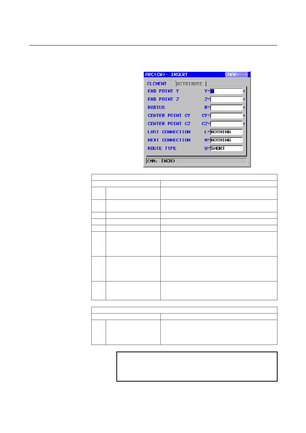
Arc (CW): G1302 (YZ plane)
Arc (CCW): G1303 (YZ plane)
ELEMENT
(INPUT DATA)
(Note 1)
Data item
Meaning
Y*
END POINT Y
Y coordinate of an arc end point
Remarks) Incremental programming is possible.
Z*
END POINT Z
Z coordinate of an arc end point
Remarks) Incremental programming is possible.
R*
RADIUS
Arc radius
CY*
CENTER POINT CY
Y coordinate of an arc center
CZ*
CENTER POINT CZ
Z coordinate of an arc center
L
LAST CONNECTION
[TANGNT] : In contact with the immediately preceding
figure
[NO SET]
: Not in contact with the immediately
preceding figure (initial value)
M
NEXT CONNECTION
[TANGNT] : In contact with the immediately preceding
figure
[NO SET]
: Not in contact with the immediately
preceding figure (initial value)
U
ROUTE TYPE
[LONG]
: An arc with a long route is made
[SHORT]
: An arc with a short route is made
(initial value)
ATTRIBUTE
(INPUT DATA)
(Note 1)
Data item
Meaning
T
ELEMENT TYPE
[PART]
: Cut as parts
[BLANK] : Cut as a blank portion
Remarks) The system sets the last data as an initial
value.
NOTE
1
‘INPUT DATA’ means the items, which are
displayed on the input data window in editing or
altering.
- 101 -