FANUC MANUAL GUIDE i. OPERATOR’S MANUAL - page 2
4.SYMBOLS USED
GENERAL
B-63874EN/05
4
SYMBOLS USED
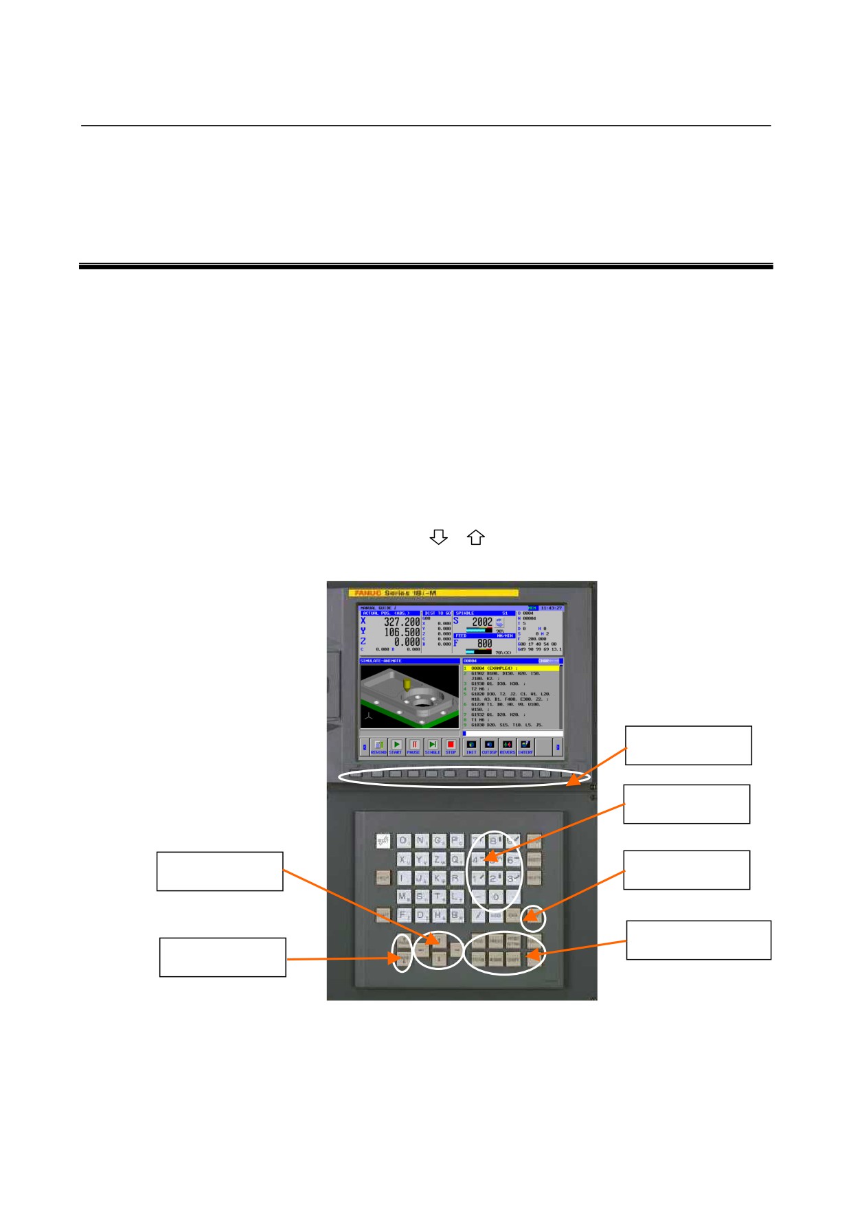
In this manual, the following conventions are used for keys.
(1) Function buttons are indicated in bold type:
Example) PROGRM, OFSET
(2) The numbers to be input by numerical keys are underlined.
Example) 12.345
(3) The input key is indicated in bold type in the same way as the
function buttons.
Example) 12.345 INPUT
(4) Soft-keys are enclosed in brackets [ ]:
Example) [LIST], [LINE]
(5) The cursor keys are indicated by the following symbols :
Example) ↑, ↓, ←, →
(6) The page keys are indicated by the following symbols :
Example)
,
Soft Key
Numeral Key
Cursor Key
INPUT Key
Function Button
Page Key
- 12 -
B-63874EN/05
GENERAL 5.NOTES ON CREATING PROGRAMS
5
NOTES ON CREATING PROGRAMS
The notes that should be observed when creating a program are
described below. Read the notes before creating a program.
1.
General notes on machining programs
<1> Use ISO code form (G code commands) basically for a
machining program. Enter a command for simple motion
directly with a G code, and use cycle machining for
complicated machining.
<2> Enter directly a tool change command involving the calling
of the next tool by using a code such as a T code and M
code or by using a subprogram call prepared by the machine
tool builder, referring to the relevant operator's manual of
the machine tool builder.
<3> Enter directly a tool length compensation command used
with a machining center by using a G code such as G43.
<4> For changing tools or tool length compensation, a similar
command is repeatedly entered. So, such a command can
be entered easily by registering a fixed form sentence
beforehand.
2.
Programmed commands required before cycle machining input
<1> When using a tool database with a CNC of the M series, be
sure to enter a D command (offset number).
<2> Be sure to enter a spindle rotation command. At the same
time, specify whether to enable or disable constant surface
speed control.
<3> No feedrate command needs to be specified, because a
feedrate command is separately entered as a cycle
machining command. However, specify a command for
feed per revolution or feed per minute as required. For
example, operator know-how on executing milling in
pocketing by feed per revolution can be utilized.
<4> Enter an M code command for switching between the
spindle and C-axis, and a command for C-axis reference
position return as required.
<5> Enter M codes such as for coolant ON/OFF as required.
<6> By setting bit 2 of parameter No. 27000 to 1, a polar
coordinate interpolation command
(G12.1) required for
machining (polar coordinate interpolation) on the XC plane
can be automatically specified during cycle machining.
Upon completion of the cycle machining, polar coordinate
interpolation is automatically cancelled.
- 13 -
5.NOTES ON CREATING PROGRAMS GENERAL
B-63874EN/05
<7> By setting bit 3 of parameter No. 27000 to 1, a cylindrical
interpolation command
(G07.1) required for machining
(cylindrical interpolation) on the ZC plane can be
automatically specified during cycle machining. Upon
completion of the cycle machining, cylindrical interpolation
is automatically cancelled.
<8> Upon completion of cycle machining, the tool always
returns to the position before the start of the cycle
machining. By setting bit 7 of parameter No. 27002 to 1,
the tool can be placed at a position different from the
position before the start of the cycle machining.
<9> When using G code system B or C with a CNC of the T
series
(T mode for a CNC for complex machining) and
specifying cycle machining (turning or milling), be sure to
switch to the absolute coordinate system by specifying G90
beforehand.
<10>For the cycle machining mentioned above, a similar
command is repeatedly entered. So, such a command can
be entered easily by registering a fixed form sentence
beforehand.
3.
Cycle machining
<1> With a CNC of the T series as well, enter a coordinate value
for milling (such as an I point coordinate in milling-based
hole machining) as a radius value even if the value is an X
coordinate.
<2> Specify an I point coordinate not as a distance from point R
but as a coordinate value.
<3> Figure data should be entered as a subprogram for
utilization in roughing, finishing, and chamfering. This
eliminates the need to enter figure data each time.
<4> In machining of a projected portion (island figure), efficient
machining can be achieved by using pocketing with an
island instead of using contouring. In this case, specify a
blank as the outer wall of a pocket.
<5> In contouring (side facing), enter a start point figure and end
point figure so that both figures contact each other. This
means that by starting not from a corner of a figure but from
an intermediate point on a straight line, undercutting due to
approaching the figure and retraction can be eliminated.
<6> If the C-axis operates as the hole machining axis in an
attempt to execute hole machining by using the C-axis as
the positioning axis, the C-axis may be set as an axis
parallel to the X-axis with parameter No. 1022. In such a
case, set the parameters below to execute hole machining in
the axis direction normal to the plane including the C-axis.
When the parameter No. 5101#0 is set to 1 :
The hole machining axis in a hole machining canned
cycle is the third axis for plane specification.
- 14 -
B-63874EN/05
GENERAL 5.NOTES ON CREATING PROGRAMS
When the parameter No. 5103#2 is set to 1 :
If an axis normal to or parallel with a specified plane is
specified during a hole machining canned cycle, the
specification is regarded as a positioning command.
<7> With a CNC of the T series as well, enter a coordinate value
for milling (such as an I point coordinate in milling-based
hole machining) as a radius value even if the value is an X
coordinate.
4.
Machining program entered on a multipath lathe
<1> When creating a machining program for a multipath lathe,
create necessary processes on the process list screen before
creating machining operations. This allows the user to
view the entire machining program more easily.
5.
Animated simulation
<1> hen performing machining simulation of a program
including a three-dimensional coordinate conversion
command, increase the dry run feedrate (for example, by
selecting the rapid traverse rate) to speed up the simulation.
<2> If a tool post is placed on the lower side when animated
simulation is performed on a multipath lathe, the machining
performed on the side opposite to the blank can be viewed
during animated simulation by pressing the [REVERS] soft
key.
- 15 -
6.MANUAL GUIDE i SIMULATOR FOR THE PERSONAL COMPUTER GENERAL B-63874EN/05
6
MANUAL GUIDE i SIMULATOR FOR THE
PERSONAL COMPUTER
This chapter describes the MANUAL GUIDE i simulator for the
personal computer.
NOTE
The specifications of the MANUAL GUIDE i
simulator for the personal computer are subject to
change as a result of product improvement.
- 16 -

B-63874EN/05 GENERAL 6.MANUAL GUIDE i SIMULATOR FOR THE PERSONAL COMPUTER
6.1
OPERATING ENVIRONMENT
6.1.1
Product Components
•
CD-ROM disk
MANUAL GUIDE i simulator software for the personal
computer
•
Hardware protection key
6.1.2
Operating Environment
•
Main computer unit
-
PC/AT-compatible machine on which
Windows 2000/XP Professional can run
-
Japanese or English must be usable on the OS used.
-
Pentium(R) III, 1 GHz or higher
-
Memory:
256 MB or more
-
Hard disk: A free space of 150 MB is required.
-
A USB1.1 port must be provided.
-
An Ethernet port must be provided (not required in the case
of package licensing).
-
For simulation using a
10.4-inch screen with no MDI
buttons, XGA (1024×786) or a higher resolution is required.
-
For simulation using a 10.4-inch screen with MDI buttons,
SXGA (1280×1024) or a higher resolution is required.
-
For simulation using a 15-inch screen with no MDI buttons,
UXGA (1600×1200) or a higher resolution is required.
-
For simulation using a 15-inch screen with MDI buttons,
QXGA (2048×1536) or a higher resolution is required.
- 17 -
6.MANUAL GUIDE i SIMULATOR FOR THE PERSONAL COMPUTER GENERAL B-63874EN/05
6.2
METHOD OF INSTALLATION
For installation, the administrator authority for the computer is
required.
Insert the CD-ROM of the MANUAL GUIDE i simulator for the
personal computer into the CD-ROM drive. Execute "SetUp.exe" on
the CD-ROM drive to start the installer.
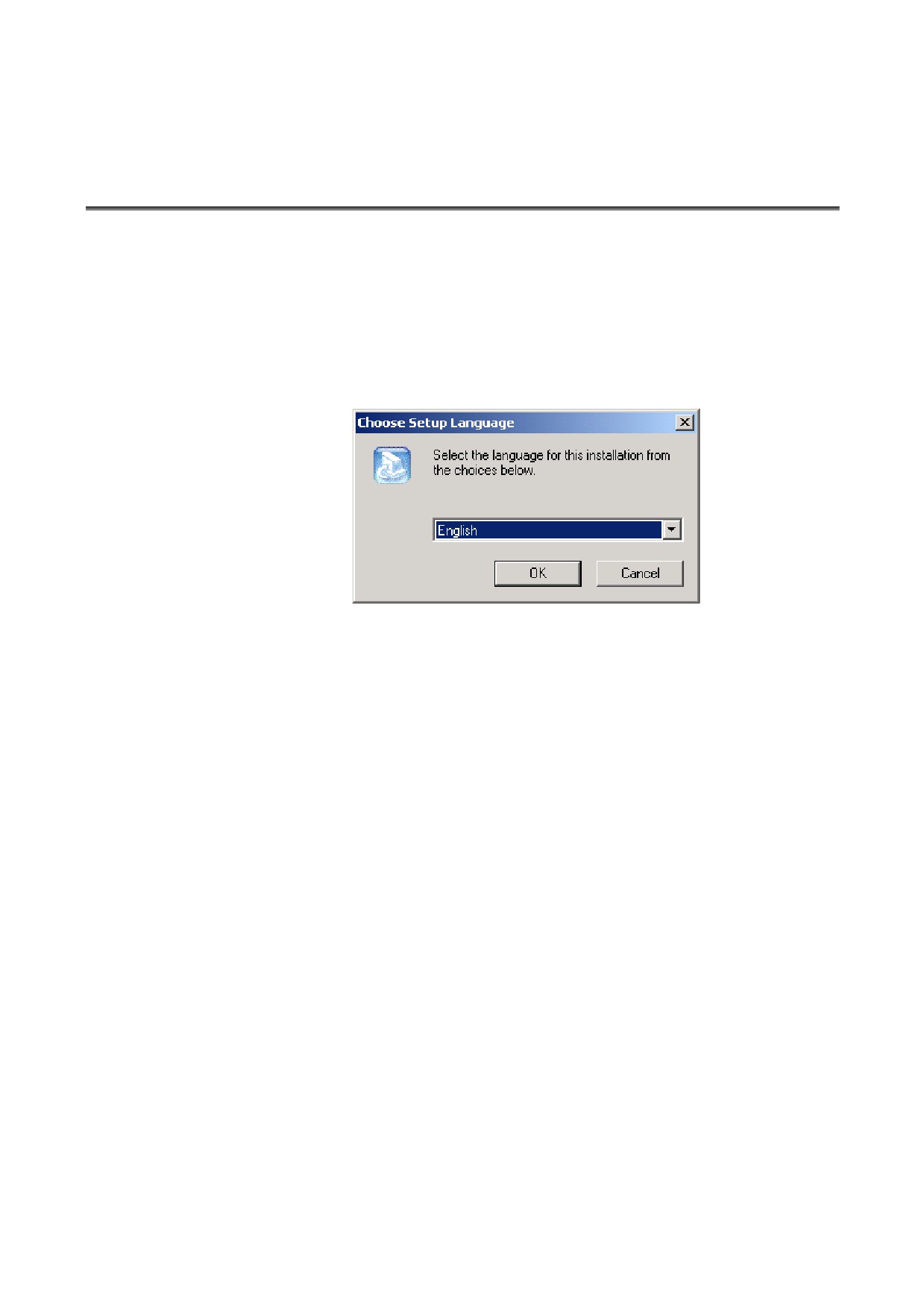
When the installer is started, a dialog box for selecting a language to
be used for setup is displayed. Select a language to be used for setup
from the list then click [OK].
- 18 -
B-63874EN/05 GENERAL 6.MANUAL GUIDE i SIMULATOR FOR THE PERSONAL COMPUTER
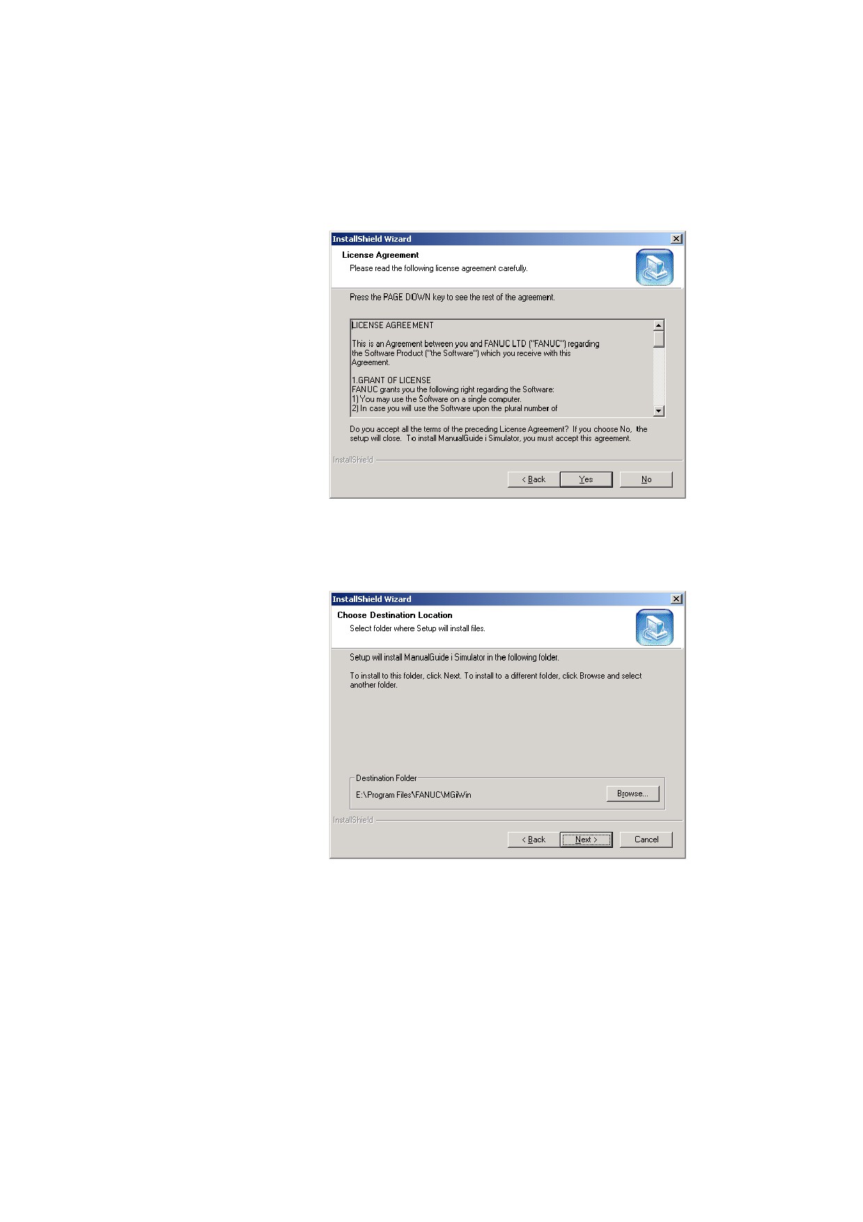
During installation, the system prompts you to agree upon the license
agreement for using this software. If you agree, click [Yes]. If you
select
[No], a dialog box for checking if the installation may be
stopped is displayed.
In the dialog box for installation destination selection, the installation
destination can be changed to a desired destination from the standard
one. Change the installation destination or click
[Next] without
changing the destination.
- 19 -
6.MANUAL GUIDE i SIMULATOR FOR THE PERSONAL COMPUTER GENERAL B-63874EN/05
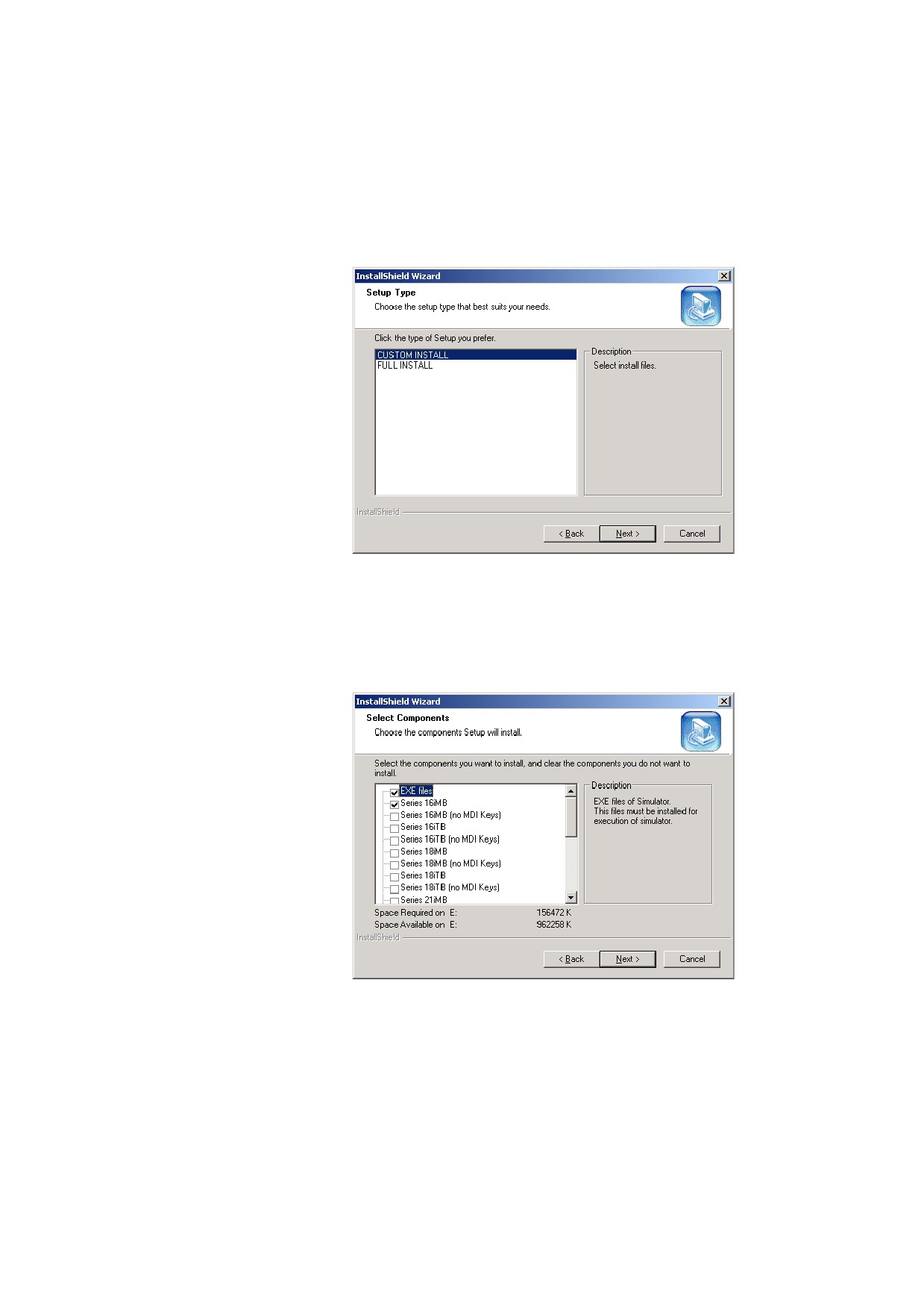
In the dialog box for setup type selection, you can select full
installation or custom installation. When full installation is selected,
a free space of about 700 MB is required. For custom installation,
the required free space varies according to the components to be
installed.
When custom installation is selected, a dialog box for selecting
components to be installed is displayed. Check each component to
be installed then click
[Next]. This dialog box is displayed also
when a component is added or deleted after installation. In this case,
check a component to be added, and uncheck a component to be
uninstalled.
Upon completion of installation, attach the hardware key to the USB
port and execute the MANUAL GUIDE i simulator.
Do not attach the hardware key to the USB port before completion of
software installation.
- 20 -
B-63874EN/05 GENERAL 6.MANUAL GUIDE i SIMULATOR FOR THE PERSONAL COMPUTER
6.3
SIMULATION CNC SELECTION
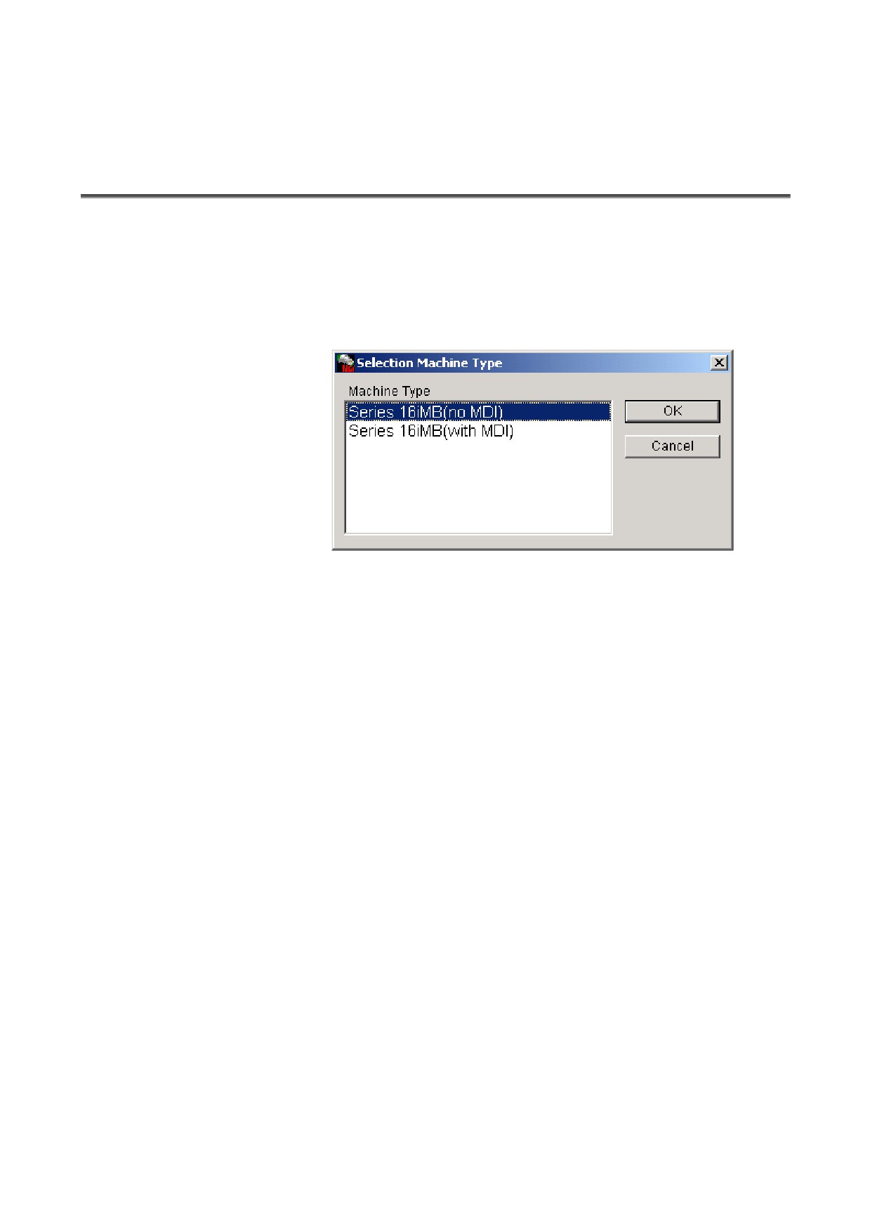
Start the MANUAL GUIDE i simulator by choosing [Start] menu →
[Programs] → [FANUC] → [ManualGuide i Simulator]. When the
MANUAL GUIDE i simulator is started, a dialog box for selecting a
simulator definition file used to execute the MANUAL GUIDE i
simulator is displayed. In this dialog box, select a definition to be
simulated then click the [OK] button to start the MANUAL GUIDE i
simulator.
The simulator definition file is a text file where information such as
CNC model and display unit size information is written in a specified
format. By editing this file, a simulator environment with a
user-specific configuration can be defined.
- 21 -
6.MANUAL GUIDE i SIMULATOR FOR THE PERSONAL COMPUTER GENERAL B-63874EN/05
6.4
FULL-SCREEN DISPLAY
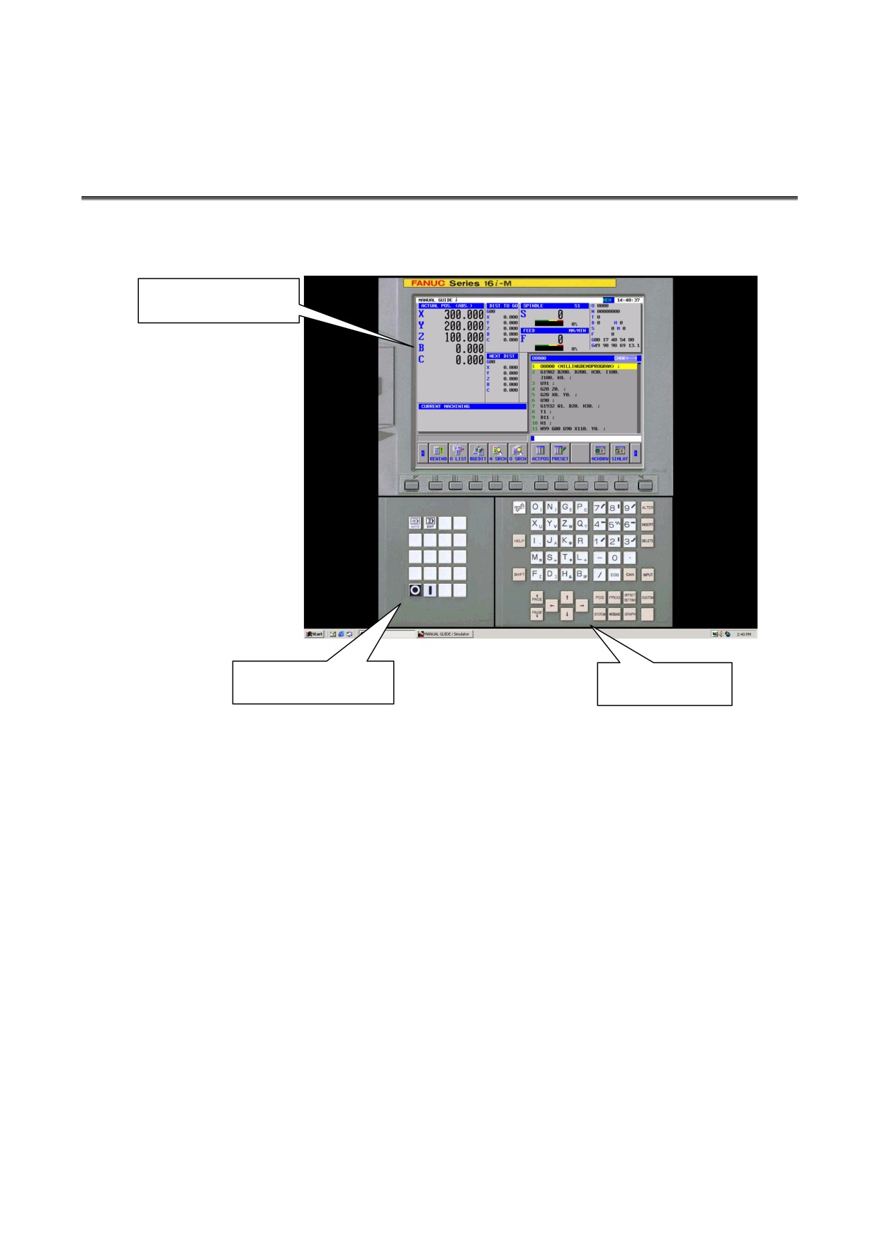
When the MANUAL GUIDE i simulator is started, the simulator is
displayed on the full screen of the personal computer.
Main simulator screen
Machine operation
MDI button
button
With the MANUAL GUIDE i simulator, the main simulator screen,
the MDI button screen operable using the mouse, and the machine
operation button screen are displayed. A soft key operation can be
performed by clicking a soft key on the main simulator screen or by
pressing a key from F1 to F12 on the keyboard of the personal
computer. Numeric values and uppercase letters can be entered
through the MDI buttons or the keyboard of the personal computer.
For CNC-specific key input, click MDI buttons or machine operation
buttons with the mouse. To quit the simulator, click the machine
operation button [{ ].
- 22 -
B-63874EN/05 GENERAL 6.MANUAL GUIDE i SIMULATOR FOR THE PERSONAL COMPUTER
6.5
PARAMETER
1
Parameters created with the FS16i/18i/21i cannot be input.
2
When using a parameter of the FS16i/18i/21i, convert the
parameter to the FS30i format.
3
Parameters in the FS30i format can be used without
modification.
4
The parameters related to the MANUAL GUIDE i function are
basically compatible.
5
Parameter data cannot be output.
6
For the
method of parameter input, refer to
"Standard_param¥Readme_j.txt" stored on the CR-ROM.
7
The standard parameters are stored on the CD-ROM. By
editing the file with the text editor and reading the edited file, the
simulator can be customized.
6.6
RESTRICTIONS ON USE
1
Simulation using full-screen display
The MANUAL GUIDE i simulator is executed using the full
screen of the personal computer.
2
Memory card input/output function
A) For input to/output from the memory card, use the memcard
folder under the installation folder. The following can be
input/output using the memory card input/output function:
- NC programs
- Parameters
- Tool database
B) The file name of the file in the memcard folder should
include the extension and be 12 characters or less.
- 23 -
6.MANUAL GUIDE i SIMULATOR FOR THE PERSONAL COMPUTER GENERAL B-63874EN/05
6.7
NOTES
1
The operation and functions listed below described in the
operator's manual cannot be used with the MANUAL GUIDE i
simulator for the personal computer.
- Operation in the MDI mode
- Operation in a manual mode (handle, jog)
- Multi-path lathe function
- Tool management function
- Setup support function
2
The MANUAL GUIDE i simulator for the personal computer has
a functional compatibility with the FS30i, but has some
specification restrictions with the FS16i/18i/21i.
3
Those functions that input external signals cannot be used.
4
This does not correspond to the hyper threading technology
function.
- 24 -

B-63874EN/05 GENERAL 6.MANUAL GUIDE i SIMULATOR FOR THE PERSONAL COMPUTER
6.8
SIMULATOR DEFINITION FILE FORMAT
The simulator definition file is a text file where information such as
CNC model and display unit size information is written in a specified
format. The ini file format of Windows is used.
6.8.1
Comment
A comment can be written only in a continuous area at the top of a
file.
A comment must start with a single quotation mark (').
A single quotation mark (') written at the start of a halfway data line
does not comment out the character string that follows.
6.8.2
Section
The following two sections are used:
Simulator_MachineSetting_MaxNumber
Simulator_MachineSettingn
(The character n represents a number from
0 to maxnumber of
Simulator_MachineSetting_MaxNumber.)
The character n in the "Simulator_MachineSettingn" section need not
be successive, but must not be duplicate. If n is duplicate, the setting
closer to the top of the file is selected. If a suffix greater than the
maxnumber key is assigned to a setting, the setting is not processed.
6.8.3
Key
The following keys are used:
maxnumber
name
cnctype
displaytype
pathtype
cnctype_title
from_dat_filepath
fileall_dat_filepath
srammgi_dat_filepath
mgidef_folderpath
mgidef_machine_type
userdef_filepath1
userdef_filepath2
keyini_filepath
virtual_memcard_folderpath
- 25 -
6.MANUAL GUIDE i SIMULATOR FOR THE PERSONAL COMPUTER GENERAL B-63874EN/05
6.8.3.1
[Simulator_MachineSetting_MaxNumber] section
Key name
: maxnumber
Outline
: Code a maximum subscript value for the simulator
definitions to be found in the file.
Character string to be set : Maximum subscript number to be found
Explanation : Code a maximum subscript value for the simulator
definitions in the simulator definition file. A search
for a simulator definition is made until n of the
Simulator_MachineSettingn
section
reaches
maxnumber. A found simulator definition is displayed
in a selection dialog box.
6.8.3.2
[Simulator_MachineSettingn] section
Key name
: name
Outline
: Code the name assigned to a simulator definition.
Character string to be set : Arbitrary
Explanation : Code the name assigned to a simulator definition. The
character string coded here is displayed in the simulator
definition selection dialog box displayed when the MGi
manager is started.
Key name
: cnctype
Outline
: Code a CNC model.
Character string to be set : "FS16i", "FS18i", "FS21i", "FS30i"
Explanation : Code the model of the CNC. If an attempt to read a
file described below such as a From.dat file fails, the
model coded in the MGi manager ini file is used.
Key name
: displaytype
Outline
: Code a display unit type.
Character string to be set
:
"10.4", "15"
Explanation : Code the type of the display unit. At present, specify
"10.4" or "15".
Key name
: pathtype
Outline
: Code a path type.
Character string to be set : "T", "TT", "TTT", "M", "TM", etc.
Explanation : Code a path type. Specify "T" for T series single-path
control. Specify "TT" for T series two-path control.
Specify "M" for the M series. Specify "TM" for
compound control.
Key name
: cnctype_title
Outline
: Set a CNC model name for display.
Character string to be set : Arbitrary
Explanation : Set a CNC model name for display.
- 26 -
B-63874EN/05 GENERAL 6.MANUAL GUIDE i SIMULATOR FOR THE PERSONAL COMPUTER
Key name
: from_dat_filepath
Outline
: Code the relative path of From.dat corresponding to a
selected simulator definition.
Character string to be set : Relative path of From.dat
Explanation : Specify the relative path of From.dat corresponding to a
selected simulator definition. The file coded here is
copied under the name "From.dat" to the memcard
directory under the simulator execution directory.
Key name
: fileall_dat_filepath
Outline
: Code the Relative path of file_all.dat corresponding to a
selected simulator definition.
Character string to be set : Relative path of file_all.dat
Explanation : Specify the relative path of file_all.dat corresponding to
a selected simulator definition. The file coded here is
copied under the name "file_all.dat" to the simulator
execution directory.
Key name
: srammgi_dat_filepath
Outline
: Code the relative path of sram_mgi.dat corresponding
to a selected simulator definition.
Character string to be set : Relative path of sram_mgi.dat
Explanation : Specify the relative path of sram_mgi.dat corresponding
to a selected simulator definition. The file coded here
is copied under the name "sram_mgi.dat" to the
simulator execution directory.
Key name
: mgidef_folderpath
Outline
: Code the relative path of the folder storing the
MANUAL GUIDE definition file of a selected
simulator definition.
Character string to be set :
Relative path of the folder storing a MANUAL GUIDE
definition file (ending with "¥").
Explanation : Code the relative path of the folder storing the
MANUAL GUIDE definition file of a selected
simulator definition. From the folder coded here, a
MANUAL GUIDE definition file matching the type of
the definition file to be specified next is copied together
with the language file to the simulator execution
directory.
Key name
: mgidef_machine_type
Outline
: Code the type of a MANUAL GUIDE definition file.
Character string to be set :
"TURN_VERTICAL",
"TURN_HORIZONTAL",
"MILLING_VERTICAL",
"MILLING_HORIZONTAL"
Explanation : Code the type
(T/M series, vertical/horizontal) of a
MANUAL GUIDE definition file. The file coded here
is copied to the simulator execution directory.
- 27 -
6.MANUAL GUIDE i SIMULATOR FOR THE PERSONAL COMPUTER GENERAL B-63874EN/05
Key name
: userdef_folderpath1
Outline
: Code the relative path of the user definition file of a
selected simulator definition.
Character string to be set : Relative path of a user definition file
Explanation : Code the relative path of the user definition file of a
selected simulator definition. The file coded here is
copied under the name "cex2datu" to the simulator
execution directory. Up to two user definition files
can be specified. If no user definition file is necessary,
specify a null character string.
Key name
: userdef_folderpath2
Outline
: Code the relative path of the user definition file of a
selected simulator definition.
Character string to be set : Relative path of a user definition file
Explanation : Code the relative path of the user definition file of a
selected simulator definition. The file coded here is
copied under the name "cex3datu" to the simulator
execution directory. Up to two user definition files
can be specified. If no user definition file is necessary,
specify a null character string.
Key name
: keyini_filepath
Outline
: Code the relative path of an MDI key setting file.
Character string to be set : Relative path of an MDI key setting file
Explanation : Code the relative path of a setting file specifying the
layout of MDI keys, and so forth.
By using
information such as character strings for input key
determination and button display positions stored in the
file specified here, the MGi manager displays the MDI
keys on the MGi manager.
- 28 -
B-63874EN/05 GENERAL 6.MANUAL GUIDE i SIMULATOR FOR THE PERSONAL COMPUTER
6.9
DISPLAY DATA ini FILE FORMAT
The display data ini file is a text file where information about images
and buttons to be arranged on the screen is specified. The ini file
format of Windows is used.
6.9.1
Comment
A comment can be written only in a continuous area at the top of a
file.
A comment must start with a single quotation mark (').
A single quotation mark (') written at the start of a halfway data line
does not comment out the character string that follows.
6.9.2
Section
The following sections are used:
[settings]
[frame_mainscreen]
[cnctitle]
[softkey]
[frame_mdikey]
[mdikey]
[frame_functionkey]
[functionkey]
[settings]
: Specifies general screen layout information.
[frame_mainscreen] : Specifies information such as screen component
positions on the CNC display section.
[cnctitle] and [softkey] below are included in
this frame.
[cnctitle]
: Setting for CNC model title section display
[softkey]
: Setting for soft key display
[frame_mdikey]
: Frame display setting for MDI key display
[mdikey]
: Setting for MDI key display
[frame_functionkey] : Setting for display of keys such as the mode
switch key other than the MDI keys
[functionkey]
: Setting for display of keys such as the mode
switch key
- 29 -
6.MANUAL GUIDE i SIMULATOR FOR THE PERSONAL COMPUTER GENERAL B-63874EN/05
6.9.3
Key
The keys are described on a section-by-section basis.
6.9.3.1
[settings] section
Key name
: bgcolor
Outline
: Specify a background color.
Setting method : bgcolor = r, g, b
Specify a number from 0 to 255 in r, g, and b.
Example: Grey is specified as the background color.
bgcolor = 128,128,128
Details
: Specify a background color by the lightness values
of red
(r), green
(g), and blue
(b). A lightness
value ranges from 0 to 255. If a value greater than
255 is specified, the specification of 255 is assumed.
The background color specified here is used as the
background color for the overall screens and frames.
Key name
: cncscrn_offsetx, cncscrn_offsety
Outline
: Specify the display position of a CNC display
section application.
Setting method : cncscrn_offsetx = x
: cncscrn_offsety = y
Each of x and y represents the number of pixels from
the top-left corner of the screen.
Example: CNCScrn.exe is displayed at
(320,60)
from the top-left corner of the screen.
cncscrn_offsetx=320
cncscrn_offsety=60
Details
: Specify the position of a CNC display section
application in pixels. Specify (x,y) in pixels, with
(x,y) = (0,0) for the top-left corner of the screen.
When an NC frame image is displayed, for example,
specify (x,y) to display the CNC display section at a
proper position.
Key name
: layout
Outline
: Code the layout of MDI keys.
Setting method : layout = QWERTY | ONG-M | ONG-T | MINI-M |
MINI-T
Example: The QWERTY layout is selected for the
MDI keys.
layout=QWERTY
Details
: Set the layout of MDI keys by using a specified
character string. Here, only a layout name is
specified.
The actual layout of keys is not
determined here.
- 30 -
B-63874EN/05 GENERAL 6.MANUAL GUIDE i SIMULATOR FOR THE PERSONAL COMPUTER
6.9.3.2
[frame_mainscreen] section
Key name
: image
Outline
: Specify the path of an image to be displayed in the
CNC display section area of the MGi manager.
Setting method : image = drive:¥dir1…¥filename
Example: image=.¥image¥frameFS30i.bmp
Details
: Specify the path of a frame image to be displayed
around the CNC display section. When no fame is
to be displayed, delete the coding of the key itself.
Either an absolute path or a relative path may be
used. The usable types of image files are bmp, jpg,
and gif. The size of an image must match the size
of the frame. Those portions that exceed the frame
are not displayed. Those portions that do not reach
the frame size are filled using the color specified by
bgcolor.
Key name
: visible
Outline
: Specify whether to display the main frame.
Setting method : visible = 0 | 1
Example: When the main frame is displayed
visible=1
Details
: Specify whether to display the main frame. When
0 is specified, the main frame is not displayed.
When 1 is specified, the main frame is displayed.
The main frame includes the NC title and soft keys.
So, when 0 is specified not to display the main frame,
the CNC display section is displayed, but the title
and soft keys are not displayed.
Key name
: left, top, width, height
Outline
: Specify the display position and size of the main
frame.
Setting method : left = left
top = top
width = width
height = height
Example: When the position of the main frame is
(230,20), and the size of the main frame
is (800,600)
left=230
top=20
width=800
height=600
Details
: Specify the position and size of the main frame in
pixels. For display position specification, assume
that the top-left corner of the screen is at (left,top) =
(0,0). When an image is to be pasted, the size must
match the size of the image.
- 31 -
6.MANUAL GUIDE i SIMULATOR FOR THE PERSONAL COMPUTER GENERAL B-63874EN/05
6.9.3.3
[cnctitle] section
Key name
: image
Outline
: Specify the path of a title image to be displayed
within the main frame.
Setting method : image = drive:¥dir1…¥filename
Example: image=.¥image¥titleFS30i.bmp
Details
: Specify the path of the file storing a title image to be
displayed. Either an absolute path or a relative
path may be used. When the image key itself is
deleted, no image is displayed, but the character
string of the title specified in the simulator definition
is displayed as text. The usable types of image
files are bmp, jpg, and gif. The size of an image
must match the size of the frame. Those portions
that exceed the frame are not displayed. Those
portions that do not reach the frame size are filled
using the color specified by bgcolor.
Key name
: visible
Outline
: Specify whether to display the title section.
Setting method : visible = 0 | 1
Example: When the title section is displayed
visible=1
Details
: Specify whether to display the title. When
0 is
specified, the title is not displayed. When
1 is
specified, the title is displayed. Specify
0, for
example, when an image pasted to the main frame
already includes a title, and no title needs to be
drawn additionally.
Key name
: left, top, width, height
Outline
: Specify the display position and size of the title
section.
Setting method : left = left
top = top
width = width
height = height
Example: When the display position of the title
section is (540,180), and the size of the
title section is (7000,400)
left=540
top=180
width=7000
height=400
Details
: Specify the display position and size of the title
section in twip. Specify a desired display position
as relative coordinates on the main frame, with
(left,top) = (0,0) for the top-left corner of the main
frame. When an image is to be pasted, the size
must match the size of the image.
- 32 -
B-63874EN/05 GENERAL 6.MANUAL GUIDE i SIMULATOR FOR THE PERSONAL COMPUTER
6.9.3.4
[softkey] section
Key name
: keynum
Outline
: Specify the number of buttons that are displayed in
the main frame and operate as soft keys.
Setting method : keynum = n
Example: When 12 soft keys are used
keynum=12
Details
: Specify the number of buttons that are displayed in
the main frame and used as function keys. The
number of buttons specified here is used to specify
the number of key pressing information items to be
read next.
Key name
: keyn (n:
0 to keynum-1)
Outline
: Code a setting to be assigned to a button used as a
key.
Setting method : keyn = key1, key2, x, y, imagefile
Example: When the first soft key is assigned to the
operation of the F1 key, the display
position is (900,8220), and an image to
be pasted is specified
key0={F1},{F1},900,8220,.¥image¥skey_l.bmp
Details
: Code information for setting of a button to be
assigned as a soft key. The following information
is to be set:
key1
Specify key information (to be described
later) to be passed to the CNC display
section application when a button is
pressed.
key2
Specify key information to be passed to
the CNC display section application
when a button is pressed while the
SHIFT button is held down.
x, y
Specify the display position of a button
in twip. For display position setting,
specify relative coordinates on the main
frame, with (x,y) = (0,0) for the top-left
corner of the main frame.
Imagefile Specify the path of the image file to be
pasted to a button. The size of an image
for a soft key is 28×28 pixels when the
CNC model specified in the simulator
definition is FS30i, and is 33×18 pixels
for other cases.
- 33 -
6.MANUAL GUIDE i SIMULATOR FOR THE PERSONAL COMPUTER GENERAL B-63874EN/05
6.9.3.5
[frame_mdikey] section
Key name
: image
Outline
: Specify the path of an image to be displayed as a
frame for MDI key display.
Setting method : image = drive:¥dir1…¥filename
Example: image=.¥image¥frameQWERTY.bmp
Details
: Specify the path of a frame image to be displayed
around the MDI keys. When no frame is to be
displayed, delete the coding of the key itself.
Either an absolute path or a relative path may be
used. The usable types of image files are bmp, jpg,
and gif. The size of an image must match the size
of the frame. Those portions that exceed the frame
are not displayed. Those portions that do not reach
the frame size are filled using the color specified by
bgcolor.
Key name
: visible
Outline
: Specify whether to display a frame for MDI key
display.
Setting method : visible = 0 | 1
Example: When a frame for MDI key display is
displayed
visible=1
Details
: Specify whether to display a frame for MDI key
display. When 0 is specified, no frame for MDI
display is displayed. When 1 is specified, a frame
for MDI key display is displayed. When
0 is
specified, the MDI keys are not displayed.
Key name
: left, top, width, height
Outline
: Specify the display position and size of a frame for
MDI key display.
Setting method : left = left
top = top
width = width
height = height
Example: When the display position of a frame for
MDI key display is (230,20), and the size
is (800,600)
left=230
top=20
width=800
height=600
Details
: Specify the display position and size of a frame for
MDI key display in pixels. For display position
specification, assume that the top-left corner of the
screen is at (left,top) = (0,0). When an image is to
be pasted, the size must match the size of the image.
- 34 -
B-63874EN/05 GENERAL 6.MANUAL GUIDE i SIMULATOR FOR THE PERSONAL COMPUTER
6.9.3.6
[mdikey] section
Key name
: keynum
Outline
: Specify the number of buttons that are displayed in a
frame for MDI key display and operate as MDI
keys.
Setting method : keynum = n
Example: When 66 MDI keys are used
keynum=66
Details
: Specify the number of buttons that are displayed in a
frame for MDI key display and operate as MDI keys.
The number of buttons specified here is used to
specify the number of key pressing information
items to be read next.
Key name
: keyn (n:
0 to keynum-1)
Outline
: Code a setting to be assigned to a button used as a
key.
Setting method : keyn = key1, key2, x , y, imagefile
Example: When the first MDI key is assigned to the
operation of "O", the display position is
(6020,1350), and an image to be pasted is
specified
key0=O,{(),6020,1350,.¥image¥o.bmp
Details
: Code information for setting of a button to be
assigned as an MDI key.
The following
information is to be set:
key1
Specify key information (to be described
later) to be passed to the CNC display
section application when a button is
pressed.
key2
Specify key information to be passed to
the CNC display section application
when a button is pressed while the
SHIFT button is held down.
x, y
Specify the display position of a button
in twip. For display position setting,
specify relative coordinates on the frame
for MDI key display, with (x,y) = (0,0)
for the top-left corner of the frame for
MDI key display.
Imagefile Specify the path of the image file to be
pasted to a button. The size of an image
for a soft key is 36×36 pixels.
- 35 -
6.MANUAL GUIDE i SIMULATOR FOR THE PERSONAL COMPUTER GENERAL B-63874EN/05
6.9.3.7
[frame_functionkey] section
Key name
: image
Outline
: Specify the path of an image to be displayed as a
frame for function key display.
Setting method : image = drive:¥dir1…¥filename
Example: image=.¥image¥frameFunc.bmp
Details
: Specify the path of a frame image to be displayed
around the function keys. When no frame is to be
displayed, delete the coding of the key itself.
Either an absolute path or a relative path may be
used. The usable types of image files are bmp, jpg,
and gif. The size of an image must match the size
of the frame. Those portions that exceed the frame
are not displayed. Those portions that do not reach
the frame size are filled using the color specified by
bgcolor.
Key name
: visible
Outline
: Specify whether to display a frame for function key
display.
Setting method : visible = 0 | 1
Example: When a frame for function key display is
displayed
visible=1
Details
: Specify whether to display a frame for function key
display. When 0 is specified, no frame for function
display is displayed. When 1 is specified, a frame
for function key display is displayed. When 0 is
specified, the function keys are not displayed.
Key name
: left, top, width, height
Outline
: Specify the display position and size of a frame for
function key display.
Setting method : left = left
top = top
width = width
height = height
Example: When the display position of a frame for
function key display is (230,20), and the
size is (800,600)
left=230
top=20
width=800
height=600
Details
: Specify the display position and size of a frame for
function key display in pixels. For display position
specification, assume that the top-left corner of the
screen is at (left,top) = (0,0). When an image is to
be pasted, the size must match the size of the image.
- 36 -
B-63874EN/05 GENERAL 6.MANUAL GUIDE i SIMULATOR FOR THE PERSONAL COMPUTER
6.9.3.8
[functionkey] section
Key name
: keynum
Outline
: Specify the number of buttons that are displayed in a
frame for function key display and operate as
function keys.
Setting method : keynum = n
Example: When two function keys are used
keynum=2
Details
: Specify the number of buttons that are displayed in a
frame for function key display and operate as
function keys. The number of buttons specified
here is used to specify the number of key pressing
information items to be read next.
Key name
: keyn (n:
0 to keynum-1)
Outline
: Code a setting to be assigned to a button used as a
key.
Setting method : keyn = key1, key2, x , y, imagefile
Example: When the first function key is assigned to
the operation of the "auto" key, the
display position is
(450,660), and an
image to be pasted is specified
key0=^r,^r,450,60,.¥image¥auto.bmp
Details
: Code information for setting of a button to be
assigned as a function key.
The following
information is to be set:
key1
Specify key information (to be described
later) to be passed to the CNC display
section application when a button is
pressed.
key2
Specify key information to be passed to
the CNC display section application
when a button is pressed while the
SHIFT button is held down.
x, y
Specify the display position of a button
in twip. For display position setting,
specify relative coordinates on the frame
for function key display, with
(x,y)
=
(0,0) for the top-left corner of the frame
for function key display.
Imagefile Specify the path of the image file to be
pasted to a button. The size of an image
for a soft key is 36×36 pixels.
- 37 -
6.MANUAL GUIDE i SIMULATOR FOR THE PERSONAL COMPUTER GENERAL B-63874EN/05
6.9.3.9 Information to be passed when a button is pressed
When specifying buttons such as soft keys, MDI keys, and function
keys in a display data ini file, specify key information to be passed to
the CNC display section application when the buttons are pressed .
The format for key specification is described below.
The format for button setting is as follows:
Setting method
:
keyn = key1, key2, x , y, imagefile
To assign the pressing of "a" when the keyn button is pressed, code
"a" in key1. To input "b" when the key is pressed while the SHIFT
key is held down, code "b" in key2.
Example: keyn = a, b, x , y, imagefile
* A character coded here is input to the CNC display section
application. So, if a character not supported by the CNC
display section application is coded, an unpredictable operation
results.
The table below indicates the CNC keys and corresponding
character strings. In an ini file, code the character strings
corresponding to CNC keys to be operated.
- 38 -

B-63874EN/05 GENERAL 6.MANUAL GUIDE i SIMULATOR FOR THE PERSONAL COMPUTER
CNC key
Corresponding
CNC key
Corresponding
character string
character string
A
a
1
1
B
b
2
2
C
c
3
3
D
d
4
4
E
e
5
5
F
f
6
6
G
g
7
7
H
h
8
8
I
i
9
9
J
j
0
0
K
k
-
-
L
l
.
.
M
m
/
/
N
n
(
{(}
O
o
)
{)}
P
p
?
?
Q
q
,
COMMA
R
r
@
(No corresponding
character string)
S
s
#
#
T
t
=
=
U
u
V
v
+
{+}
W
w
[
[
X
x
]
]
Y
y
&
(No corresponding
character string)
Z
z
SP
SPACE
- 39 -

6.MANUAL GUIDE i SIMULATOR FOR THE PERSONAL COMPUTER GENERAL B-63874EN/05
CNC key
Corresponding
CNC key
Corresponding
character string
character string
RESET
@
SOFTKEY 1
Q
HELP
{‘}
SOFTKEY 2
A
SHIFT
SHIFT
SOFTKEY 3
Z
ALTER
`
SOFTKEY 4
X
INSERT
^n
SOFTKEY 5
C
DELETE
DEL
SOFTKEY 6
V
INPUT
{ENTER}
SOFTKEY 7
B
PAGEUP
PDUP
SOFTKEY 8
N
PAGEDOWN
PGDN
SOFTKEY 9
M
UP
E
SOFTKEY 10
L
DOWN
D
SOFTKEY 11
R
LEFT
S
SOFTKEY 12
T
RIGHT
F
SOFTKEY 13
Y
MEM MODE
^r
SOFTKEY 14
U
EDIT MODE
^d
SOFTKEY 15
I
EXIT
%{F4}
SOFTKEY 16
O
SOFTKEY L
W
SOFTKEY 17
G
SOFTKEY R
P
SOFTKEY 18
H
SOFTKEY 19
¥
- 40 -
II. OPERATION