FANUC MANUAL GUIDE i. OPERATOR’S MANUAL - page 1
SAFETY PRECAUTIONS
B-63874EN/05
1.1
DEFINITION OF WARNING, CAUTION, AND NOTE
This manual includes safety precautions for protecting the user and
preventing damage to the machine. Precautions are classified into
Warning and Caution according to the degree of the risk or the
severity of damage.
Also, supplementary information is described as Note.
Read the Warning, Caution, and Note thoroughly before attempting to
use the machine.
WARNING
Applied when there is a danger of the user being
injured or when there is a damage of both the user
being injured and the equipment being damaged if
the approved procedure is not observed.
CAUTION
Applied when there is a danger of the equipment
being damaged, if the approved procedure is not
observed.
NOTE
The Note is used to indicate supplementary
information other than Warning and Caution.
- Read this manual carefully, and store it in a safe place.
s-2
B-63874EN/05
SAFETY PRECAUTIONS
1.2
GENERAL WARNINGS AND CAUTIONS
To ensure safety while using a machine featuring the MANUAL
GUIDE i function, observe the following precautions:
WARNING
1
Confirm, on the screen, that the data has been entered
correctly before proceeding to the next operation.
Attempting operation with incorrect data may cause the
tool to strike the workpiece or machine, possibly
breaking the tool or machine or injuring the operator.
2
Before starting the machine using the tool compensation
function, carefully determine the direction of
compensation and the compensation value, and ensure
that the tool will not strike the workpiece or machine.
Otherwise the tool or machine may be damaged or the
operator may be injured.
3
When using constant surface speed control, set the
maximum rotating speed of the spindle to a value that is
allowed for the workpiece and workpiece hold unit.
Otherwise, the workpiece or hold unit may be removed
by centrifugal force to damage the tool machine or injure
the operator.
4
Set all necessary parameters and data items before
starting MANUAL GUIDE i operations. Note that if the
cutting conditions are not suitable for the workpiece, the
tool may be damaged or the operator may be injured.
5
After creating a machining program using MANUAL
GUIDE i functions, do no run the machine on that
program immediately. Instead, confirm every step of the
resultant program, and make sure that the tool path and
machining operation are correct and that the tool will not
strike the workpiece or machine. Before starting
production machining, run the machine with no
workpiece attached to the machine to make sure that the
tool will not strike a workpiece or the machine. If the tool
strikes the machine and/or work-piece, the tool and/or
machine may be damaged, and even injuries the
operator.
CAUTION
After pressing the power-on button, do not touch any
keys on the keyboard until the initial screen appears.
Some keys are used for maintenance or special
operations such that pressing such a key may cause an
unexpected operation.
s-3
B-63874EN/05
TABLE OF CONTENTS
TABLE OF CONTENTS
SAFETY PRECAUTIONS
s-1
I. GENERAL
1
OVERVIEW OF THIS MANUAL
3
2
READ AT FIRST
4
3
ALL-IN-ONE SCREEN
9
4
SYMBOLS USED
12
5
NOTES ON CREATING PROGRAMS
13
6
MANUAL GUIDE i SIMULATOR FOR THE PERSONAL
COMPUTER
16
6.1
OPERATING ENVIRONMENT
17
6.1.1
Product Components
17
6.1.2
Operating Environment
17
6.2
METHOD OF INSTALLATION
18
6.3
SIMULATION CNC SELECTION
21
6.4
FULL-SCREEN DISPLAY
22
6.5
PARAMETER
23
6.6
RESTRICTIONS ON USE
23
6.7
NOTES
24
6.8
SIMULATOR DEFINITION FILE FORMAT
25
6.8.1
Comment
25
6.8.2
Section
25
6.8.3
Key
25
6.8.3.1
[Simulator_MachineSetting_MaxNumber] section
26
6.8.3.2
[Simulator_MachineSettingn] section
26
6.9
DISPLAY DATA ini FILE FORMAT
29
6.9.1
Comment
29
6.9.2
Section
29
6.9.3
Key
30
6.9.3.1
[settings] section
30
6.9.3.2
[frame_mainscreen] section
31
6.9.3.3
[cnctitle] section
32
6.9.3.4
[softkey] section
33
6.9.3.5
[frame_mdikey] section
34
6.9.3.6
[mdikey] section
35
6.9.3.7
[frame_functionkey] section
36
6.9.3.8
[functionkey] section
37
6.9.3.9
Information to be passed when a button is pressed
38
c-1
TABLE OF CONTENTS
B-63874EN/05
II. OPERATION
1
OVERVIEW OF THE PROCEDURE
43
1.1
MAIN FEATURES OF MANUAL GUIDE i
44
2
MACHINING PROGRAM FORMAT
46
3
EDITING MACHINING PROGRAMS
48
3.1
MACHINING PROGRAM WINDOW AND EIDITNG
49
3.2
CREATING MACHINING PROGRAMS
51
3.3
EDITING IN A PROGRAM LIST
52
3.4
SEARCHING FOR A MACHINING PROGRAM TO BE EDITED
54
3.5
BASIC EDITING OPERATIONS OF PART PROGRAM
55
3.5.1
Entering a Word (INSERT key)
55
3.5.2
Modifying a Word (ALTER key)
55
3.5.3
Modifying the Numeric Value of a Word (ALTER key)
55
3.5.4
Deleting a Word (DELETE key)
56
3.5.5
Modifying a Block (ALTER key)
56
3.5.6
Deleting a Block (DELETE key)
56
3.5.7
Changing the Program Number (ALTER key)
56
3.6
SEARCH (FORWARD AND BACKWARD)
57
3.7
CUT
58
3.8
COPY
58
3.9
PASTE
59
3.10
DELETE
59
3.11
KEY-IN PASTE
60
3.12
UNDO, REDO
61
3.13
M-CODE MENU
62
3.14
FIXED FORM SENTENCE INSERTION
64
4
EDITING CYCLE MACHINING OPERATIONS
66
4.1
ENTERING THE START COMMAND
67
4.2
SELECTING A CYCLE MACHINING TYPE
69
4.3
ENTERING CYCLE MACHINING DATA
71
4.4
SELECTING FIGURES
73
4.5
ENTERING FIXED FORM FIGURE DATA FOR CYCLE MACHINING
75
4.6
ENTERING ARBITRARY FIGURE DATA FOR CYCLE MACHINING
78
4.7
ENTERING CONTOUR PROGRAMS
81
4.8
ENTERING THE END COMMAND
83
4.9
CHANGING CYCLE MACHINING AND FIGURE DATA
83
c-2
B-63874EN/05
TABLE OF CONTENTS
5
DETAILED DESCRIPTIONS ABOUT ENTERING ARBITRARY
FIGURES
84
5.1
INCREMENTAL PROGRAMMING
85
5.1.1
Arbitrary Figures for the XY Plane
86
5.2
ARBITRARY FIGURES FOR THE YZ PLANE
97
5.3
ARBITRARY FIGURES FOR THE POLAR COORDINATE
INTERPOLATION PLANE (XC PLANE)
107
5.4
ARBITRARY FIGURES FOR THE CYLINDRICAL SURFACE
(ZC PLANE)
118
5.5
ARBITRARY FIGURES FOR TURNING (ZX PLANE)
129
5.6
ARBITRARY FIGURE COPY FUNCTIONS
140
5.6.1
Selecting an Arbitrary Figure Copy Function
140
5.6.2
Copy Condition Input Screen
141
5.6.3
Executing Arbitrary Figure Copy Operation
145
5.6.4
Figure after Arbitrary Figure Copy Execution
147
5.6.5
Notes on Arbitrary Figure Copy Operation
147
6
OPERATIONS IN THE MEM MODE
148
6.1
REWINDING A MACHINING PROGRAM
149
6.2
EDITING WITH THE MACHINING PROGRAM LIST
149
6.3
SEARHING FOR A SEQUENCE NUMBER IN A PROGRAM
150
6.4
SELECTING A PROGRAM FOR MACHINING OPERATION
150
6.5
CHANGING THE CURRENT POSITION DISPLAY
150
6.6
PRESETTING RELATIVE COORDINATES
151
6.7
DISPLAYING MEASUREMENT RESULTS
152
6.8
DISPLAYING THE MACHINING SIMULATION WINDOW
152
6.9
DISPLAYING THE DRAWING-DURING-MACHINING WINDOW
152
6.10
BG EDITING
153
6.11
NC PROGRAM CONVERSION
153
6.12
NEXT-BLOCK DISPLAY FUNCTION
154
6.13
PROGRAM RESTART FUNCTION
156
6.13.1
[P TYPE] Soft-key
156
6.13.2
[Q TYPE] Soft-key
157
7
OPERATIONS IN THE MDI MODE
158
8
OPERATIONS IN THE MANUAL MODE (HANDLE AND JOG)
160
9
MACHINING SIMULATION AND DRAWING DURING MACHINING. 161
9.1
DRAWING DURING MACHINING (TOOL PATH)
163
c-3
TABLE OF CONTENTS
B-63874EN/05
9.1.1
Program Selection Operation and Other Operations in Drawing during
Machining
164
9.1.2
Selecting Whether to Display the Tool Path or Not in Drawing during
Machining
165
9.1.3
Scaling, Movement, and Other Operations in Drawing during Machining
165
9.2
MACHINING SIMULATION (TOOL PATH) (FOR Series 16i/18i/21i)
168
9.2.1
Program Selection Operation and Other Operations in Machining Simulation
(Tool Path)
170
9.2.2
Execution Operations in Machining Simulation (Tool Path)
170
9.2.3
Scaling, Movement, and Other Operations in Machining Simulation
(Tool Path)
171
9.3
MACHINING SIMULATION (ANIMATED) (FOR Series 16i/18i/21i)
172
9.3.1
Program Selection Operation and Other Operations in Machining Simulation
(Animated)
174
9.3.2
Execution Operations in Machining Simulation (Animated)
174
9.3.3
Scaling, Movement, and Other Operations in Machining Simulation
(Animated)
175
9.3.4
Notes on Machining Simulation
175
9.4
MACHINING SIMULATION (TOOL PATH) (FOR Series 30i)
177
9.4.1
Program Selection Operation and Other Operations in Machining Simulation
(Tool Path)
181
9.4.2
Execution Operations in Machining Simulation (Tool Path)
182
9.4.3
Scaling, Movement, and Other Operations in Machining Simulation
(Tool Path)
182
9.5
MACHINING SIMULATION (ANIMATED) (FOR Series 30i)
183
9.5.1
Program Selection Operation and Other Operations in Machining Simulation
(Animated)
183
9.5.2
Execution Operations in Machining Simulation (Animated)
183
9.5.3
Scaling, Movement, and Other Operations in Machining Simulation
(Animated)
184
9.6
DATA HANDLED DURING MACHINING SIMULATION (FOR Series 30i) 185
9.7
FUNCTIONS OPERATING DIFFERENTLY BETWEEN MACHINING
SIMULATION AND AUTOMATIC OPERATION (FOR Series 30i)
186
9.7.1
Functions That Cannot Be Used for Machining Simulation
187
9.7.2
Functions That Can Be Used for Machining Simulation (Milling System)
187
9.8
CHANGING WORKPIECE COORDINATE DURING MACHINING
SIMULATION (ANIMATION, TOOL PATH DRAWING)
188
9.9
SETTING OF DATA FOR ANIMATION
190
9.10
SPINDLE MOVEMENT ANIMATION FOR AUTOMATIC LATHES
217
9.10.1 Function
217
9.10.2 Start Command of Reflection
217
9.10.3 End Command of Reflection
218
c-4
B-63874EN/05
TABLE OF CONTENTS
9.10.4 Simulation and Actual Working of the Machine
219
10
SETTING DATA
222
10.1
SETTING THE WORKPIECE COORDINATE DATA
223
10.1.1
[MEASUR] Soft Key
225
10.1.2
[+INPUT] Soft Key
226
10.2
SETTING TOOL OFFSET DATA
228
10.2.1
[MEASUR] Soft Key
230
10.2.2
[+INPUT] Soft Key
231
10.2.3
[INP.C.] Soft Key
232
10.3
REGISTERING FIXED FORM SENTENCES
233
10.3.1 Registering a New Fixed Form Sentence
236
10.3.2 Modifying a Fixed Form Sentence
238
10.3.3 Deleting a Fixed Form Sentence
239
10.3.4 Initialization to Standard Fixed Form Sentences
239
11
BACKGROUND EDITING
240
11.1
STARTING BACKGROUND EDITING
241
11.2
ENDING BACKGROUND EDITING
242
11.3
OPERATIONS DURING BACKGROUND EDITING
242
12
NC PROGRAM CONVERSION FUNCTION
243
12.1
BASIC SPECIFICATIONS
244
12.2
OPERATING THE NC PROGRAM CONVERSION FUNCTION
246
12.3
RESTRICTIONS
249
13
TOOL DATA BASE FUNCTION
251
13.1
SETTING OF TOOL OFFSET DATA
252
13.2
SETTING OF TOOL DATA
253
13.2.1 Setting of Tool Type
253
13.2.2 Editing of Tool Name
254
13.2.3 Setting of Tool Set
254
13.2.4 Entering of Tool Data
254
13.2.5 Cutting Edge angle of Tool Data Base Function
255
13.2.6 Initializing of Tool Data
256
13.3
SELECTING TOOL DATA AT PROGRAM ENTERING
257
13.4
SETTING OF TOOL GRAPHIC DATA
258
13.4.1 Tool Graphic Data
258
13.5
ACCESSING TOOL DATA BASE FUNCTION
259
13.5.1 Basic Specifications
259
13.5.2 System Variables
260
13.5.3 Reading
261
13.5.4 Writing
261
c-5
TABLE OF CONTENTS
B-63874EN/05
13.5.5 Copying
261
13.5.6 Initialization
262
13.5.7 Initialization of All Tool Data
262
14
EDITING OF FREE FIGURE AND FIXED FORM FIGURE OF
SUBPROGRAM FORM
263
14.1
EDITING A FREE FORM FIGURE SUBPROGRAM
264
14.2
WARNING MESSAGE
267
14.3
EDITING A FIXED FORM FIGURE SUBPROGRAM
267
15
SHORTCUT KEY OPERATIONS
268
15.1
SHORTCUTS FOR VARIOUS CONFIRMATION OPERATIONS
269
15.2
SHORTCUTS FOR RANGE SELECTION
269
15.3
SHORTCUTS FOR COPY OPERATION
269
15.4
SHORTCUTS FOR CUT OPERATION
269
15.5
SHORTCUTS FOR THE BASE SCREEN SOFT KEYS
270
15.6
SHORTCUT FOR STARTING THE CYCLE CHANGE SCREEN
270
15.7
SHORTCUTS FOR THE MENU SELECTION SCREEN
270
15.8
SHORTCUTS FOR THE REGULAR PROGRAM INSERTION SCREEN.. 270
15.9
SHORTCUTS FOR THE M CODE INSERTION SCREEN
271
15.10
SHORTCUTS FOR THE PROGRAM LIST SCREEN
271
15.11
SHORTCUTS FOR THE PROGRAM CREATION SCREEN
271
15.12
SHORTCUTS FOR THE COMMENT EDITING SCREEN
271
15.13
SHORTCUTS FOR THE SEARCH SCREEN
271
15.14
SHORTCUTS FOR THE CYCLE INPUT SCREEN
272
15.15
SHORTCUT FOR THE WORKPIECE COORDINATE SYSTEM
SETTING SCREEN
272
15.16
SHORTCUT FOR THE TOOL OFFSET SETTING SCREEN
272
15.17
SHORTCUTS FOR THE REGULAR PROGRAM REGISTRATION
SCREEN
272
15.18
SHORTCUTS FOR THE CREATION SCREEN FOR REGULAR
PROGRAM REGISTRATION
273
15.19
SHORTCUTS FOR THE ALTER SCREEN FOR REGULAR PROGRAM
REGISTRATION
273
15.20
SHORTCUTS FOR THE PRESET SCREEN
273
15.21
SHORTCUT FEEDRATE THE MEASUREMENT RESULT SCREEN
273
15.22
SHORTCUT FOR THE MANUAL MEASUREMENT SCREEN
273
15.23
SHORTCUT FOR VARIOUS SETTING SCREENS
273
15.24
SHORTCUTS FOR THE FREE FIGURE MAIN SCREEN
274
c-6
B-63874EN/05
TABLE OF CONTENTS
15.25 SHORTCUTS FOR THE FREE FIGURE INPUT SCREEN
274
15.26 SHORTCUTS FOR THE FREE FIGURE CREATION SCREEN
274
16
HELP SCREEN
275
17
MEMORY CARD INPUT/OUTPUT FUNCTION
277
17.1
MEMORY CARD INPUT/OUTPUT OF PART PROGRAM
278
17.1.1 Memory Card Input/Output Screen of Part Program
278
17.1.2 Memory Card Output Operation for Part Program
279
17.1.3 Memory Card Input Operation for Part Program
282
17.1.4 File Format Allowed for Memory Card Input/Output
283
17.2
MEMORY CARD INPUT/OUTPUT OF TOOL DATA
284
17.2.1 Memory Card Input/Output Screen of Tool Data
284
17.2.2 Memory Card Output Operation for Tool Data
285
17.2.3 Memory Card Input Operation for Tool Data
286
17.2.4 Data Format
286
17.3
MEMORY CARD INPUT/OUTPUT OF FIXED FORM SENTENCES
287
17.3.1 Memory Card Input/Output Screen of Fixed Form Sentences
287
17.3.2 Output Fixed Form Sentences
288
17.3.3 Input Fixed Form Sentences
289
17.3.4 Format of Fixed Form Sentences
289
18
HANDLING LARGE PROGRAMS
290
18.1
SETTING A MAXIMUM PROGRAM SIZE THAT CAN BE HANDLED
291
18.2
HANDLING A PROGRAM LARGER THAN THE MAXIMUM
ALLOWABLE SIZE
292
19
CALCULATOR FUNCTION
294
19.1
CALCULATOR FUNCTION
295
20
AUTOMATIC SETTING OF INITIAL VALUE DATA
298
20.1
AUTOMATIC SETTING OF INITIAL VALUES ON THE INPUT DATA
SCREEN
299
20.2
AUTOMATIC TOOL DEFINITION BLOCK COPY
299
21
SUPPORT FOR FOLDER MANAGEMENT (FOR Series 30i ONLY) 300
21.1
PROGRAM LIST SCREEN
301
21.1.1 Data Displayed in the Program List
301
21.1.2 Operations Added for the Program List Screen
302
21.1.3 Support for the Data Server
303
21.2
MEMORY CARD I/O SCREEN
304
21.3
SUBPROGRAM TAB ON THE CYCLE FIGURE SELECTION SCREEN .. 304
21.4
OUTPUT OF AN ARBITRARY FIGURE AS A SUBPROGRAM
304
c-7
TABLE OF CONTENTS
B-63874EN/05
21.5
DISPLAY OF ARBITRARY FIGURES OF M98 SUBPROGRAMS
305
22
SCREEN HARD COPY
306
23
DISPLAYING MACHINING TIME (FOR Series 16i/18i/21i ONLY) ... 307
23.1
FORMAT OF MACHINING TIME DATA
308
23.2
OPERATION FOR INSERTING MACHINING TIME
309
23.3
DISPLAY MACHINING TIME
311
24
PROGRAM COORDINATE SYSTEM CHANGING FUNCTION AND
TOOL OFFSET MEMORY CHANGING FUNCTION
312
24.1
PROGRAM COORDINATE SYSTEM CHANGING FUNCTION
313
24.1.1 COORDINATE SYSTEM SELECTION COMMAND
313
24.1.2 COORDINATE OF ARBITRARY FIGURES (XZ, ZC, ZY PLANE)
315
24.1.3 MACHINING SIMULATION
316
24.1.4 STATUS DIPLAY
317
24.2
TOOL OFFSET MEMORY CHANGING FUNCTION
318
24.2.1 TOOL OFFSET DATA WINDOW
318
24.2.2 WORKPIECE SHIFT OFFSET DATA WINDOW
320
24.3
SET-UP GUIDANCE FUNCTIONS
321
24.3.1 MANUAL MEASUREMENT
321
24.3.2 MEASUREMENT CYCLE
321
24.3.3 MEASUREMENT RESULT DISPLAY SCREEN
321
24.4
CAUTIONS
322
III. CYCLE MACHINING TYPES
1 MILLING
325
1.1
HOLE MACHINING BY MILLING
335
1.1.1
Hole Machining Type Block
335
1.1.2
Hole Position Block (XY Plane)
351
1.1.3
Hole Position Block (YZ Plane)
359
1.1.4
Hole Position Block (XC Plane and End Face)
360
1.1.5
Hole Position Block (ZC Plane and Cylindrical Surface)
362
1.1.6
Hole Position Block (XA Plane and Cylindrical Surface)
362
1.2
HOLE MACHINING BY TURNING (WITH THE TOOL ROTATED)
363
1.2.1
Machining Type Blocks for Hole Machining by Turning
(with the Tool Rotated)
363
1.3
FACING
370
1.3.1
Machining Type Blocks for Facing
370
1.3.2
Fixed Form Figure Blocks for Facing (XY Plane)
376
1.3.3
Fixed Form Figure Blocks for Facing (YZ Plane, XC Plane)
379
1.3.4
Arbitrary Figure Blocks for Facing (XY Plane)
380
1.3.5
Arbitrary Figure Blocks for Facing (YZ Plane, XC Plane, ZC Plane, XA Plane)381
c-8
B-63874EN/05
TABLE OF CONTENTS
1.4
CONTOURING
382
1.4.1
Machining Type Blocks for Contouring
382
1.4.2
Fixed Form Figure Blocks for Contouring (XY Plane)
403
1.4.3
Fixed Form Figure Blocks for Contouring (YZ Plane, XC Plane)
406
1.4.4
Arbitrary Figure Blocks for Contouring (XY Plane)
407
1.4.5
Arbitrary Figure Blocks for Contouring
(YZ Plane, XC Plane, ZC Plane, XA Plane)
409
1.5
EMBOSS MACHINING
410
1.5.1
Machining Type Blocks for Emboss machining
410
1.5.2
Arbitrary Figure Blocks for Emboss machining (XY Plane)
420
1.5.3
Arbitrary Figure Blocks for Emboss machining
(YZ Plane, XC Plane, ZC Plane, XA plane)
421
1.6
POCKETING
422
1.6.1
Machining Type Blocks for Pocketing
422
1.6.2
Fixed Form Figure Blocks for Pocketing (XY Plane)
435
1.6.3
Fixed Form Figure Blocks for Pocketing (YZ Plane, XC Plane)
438
1.6.4
Arbitrary Figure Blocks for Pocketing (XY Plane)
439
1.6.5
Arbitrary Figure Blocks for Pocketing
(YZ Plane, XC Plane, ZC Plane, XA Plane)
441
1.7
GROOVING
442
1.7.1
Machining Type Blocks for Grooving
442
1.7.2
Fixed Form Figure Blocks for Grooving (XY Plane)
457
1.7.3
Fixed Form Figure Blocks for Grooving (YZ Plane, XC Plane)
462
1.7.4
Arbitrary Figure Blocks for Grooving (XY Plane)
463
1.7.5
Arbitrary Figure Blocks for Grooving
(YZ Plane, XC Plane, ZC Plane, XA Plane)
464
1.8
C-AXIS GROOVING
465
1.8.1
Machining Type Blocks for C-axis Grooving
465
1.8.2
Figure Blocks for C-axis Grooving and A-axis Grooving
467
1.9
REAR END FACING BY MILLING
472
1.9.1
Rear End Facing
472
1.10
ADDRESS SETTING OF ROTATION AXIS
474
1.10.1 Support for C-Axis Machining with Rotation Axis
474
1.11
C AXIS CLAMPING M CODE OUTPUT
476
1.11.1 Outline
476
1.11.2 Value of M Code Output
476
1.11.3 Distinction between Main and Sub Spindle
477
1.11.4 Position of M Code Output
477
2
TURNING
480
2.1
HOLE MACHINING (WORKPIECE ROTATION)
483
2.1.1
Machining Type Blocks for Hole Machining (Workpiece Rotation)
483
2.2
TURNING
488
c-9
TABLE OF CONTENTS
B-63874EN/05
2.2.1
Machining Type Blocks for Turning
488
2.2.2
Arbitrary Figure Blocks for Turning
516
2.3
TURNING GROOVING
517
2.3.1
Machining Type Blocks for Turning Grooving
517
2.3.2
Fixed Form Figure Blocks for Turning Grooving
544
2.4
THREADING
559
2.4.1
Machining Type Blocks for Threading
559
2.4.2
Fixed Form Figure Blocks for Threading
564
2.5
REAR END FACING BY TURNING
569
2.5.1
Rear End Facing
569
3 SLANT FACE MACHINING (COORDINATE CONVERSION)
571
3.1
SUPPORTABLE MACHINE CONFIGURATION
572
3.2
SLANT FACE MACHINING COMMAND
(COORDINATE CONVERSION)
573
IV. MULTI-PATH LATHE FUNCTIONS
(FOR Series 16i/18i/21i ONLY)
1
MULTI-PATH LATHE APPLICATION
581
1.1
PREPARATION
582
1.1.1
Machine Configuration Setting
582
1.1.2
Set Icon for Selected Turret
583
1.2
OPERATIONS OF MULTI-PATH LATHE
584
1.2.1
Changing Screens for Each Path
584
1.2.1.1
Changing by a soft-key
584
1.2.1.2
Changing by a switch on a machine operator’s panel
584
1.3
ANIMATION FOR MULTI-PATH LATHE
585
1.3.1
Tool Path Drawing During Machining and Tool Path Machining Simulation
585
1.3.2
Machining Simulation (Animation)
586
1.4
MACHINING SIMULATION FOR EACH PATH
587
1.5
OTHERS
589
2
SIMULTANEOUS ALL PATH DISPLAY / EDITING FUNCTION
590
2.1
OUTLINE
591
2.2
DETAILS
592
2.2.1
How to Start
592
2.2.2
How to Finish
592
2.3
SCREEN CONFIGURATION
593
2.3.1
Display Position of Each Path
593
2.3.2
Status Display Part
594
2.3.3
Current Position Display Part
595
2.3.4
Program Display Part
595
c-10
B-63874EN/05
TABLE OF CONTENTS
2.4
HOW TO SELECT PATH
596
2.5
OTHERS
596
3
PROCESS LIST EDITING FUNCTION
597
3.1
PREPARATION
598
3.1.1
Parameter
598
3.2
START AND END OPERATIONS
599
3.2.1
Start
599
3.2.2
End
600
3.3
DISPLAY CONTENTS
601
3.3.1
Cell
601
3.3.2
Current Cell
601
3.3.3
Spindle
602
3.3.4
Turret
602
3.3.5
Waiting Line
602
3.3.6
Transfer
603
3.4
BASIC OPERATIONS
604
3.4.1
Basic Operations
604
3.5
EDITING OPEARTIONS
605
3.5.1
Insertion of a Cell
606
3.5.2
Deletion of a Cell
607
3.5.3
Copying of a Cell
609
3.5.4
Moving of a Cell
611
3.5.5
Modification of Process Name
614
3.5.6
Program Edit
615
3.5.7
Assign of Waiting
617
3.5.8
Release of Waiting
620
3.5.9
Assign of Transfer
622
3.5.10
Release Transfer
624
3.5.11
Addition of Optional Block Skip for Each Path Program Check
626
3.5.12
Deletion of Optional Block Skip for Each Path Program Check
628
3.6
DEALING OF THE PART PROGRAM WITH UNFITTED TO PROCESS
LIST FORM
629
3.7
FORMAT
631
3.8
OTHERS
631
V. TOOL MANAGEMENT FUNCTION
(FOR Series 16i/18i/21i ONLY)
1 ASSOCIATING TOOL NUMBERS WITH OFFSET NUMBERS
635
1.1
SELECTING THE SCREEN FOR ASSOCIATING A TOOL NUMBER
WITH A OFFSET NUMBER
636
c-11
TABLE OF CONTENTS
B-63874EN/05
1.2
SCREEN DISPLAY ITEMS
637
1.3
DISABLE WARNING MESSAGE
638
2
VIEWING AND SETTING TOOL OFFSET VALUES
639
2.1
SELECTING THE TOOL NUMBER-BY-TOOL NUMBER TOOL OFFSET
SETTING SCREEN
640
2.2
SCREEN DISPLAY ITEMS
641
2.3
TOOL OFFSET
643
2.4
NOTES
644
2.5
DISABLE WARNING MESSAGE
647
3
VIEWING AND SETTING TOOL MANAGEMENT DATA
648
3.1
SELECTING THE TOOL MANAGEMENT DATA SETTING SCREEN
649
3.2
MAGAZINE DATA SCREENS (MAGAZINE 1 TO 4)
650
3.2.1
Screen Display Items
650
3.2.2
Displayed Warning Messages
651
3.3
SPINDLE AND STANDBY POSITION TOOL DISPLAY SCREEN
652
3.3.1
Screen Display Items
652
3.3.2
Displayed Warning Messages
653
4
VIEWING AND SETTING LIFE MANAGEMENT DATA
654
4.1
SELECTING THE LIFE MANAGEMENT DATA SETTING SCREEN
655
4.2
SCREEN DISPLAY ITEMS
656
4.3
CHANGING TOOL PRIORITY
658
4.4
UPDATING LIFE VALUES DISPLAYED ON THE TOOL LIFE DATA
SCREEN
659
4.4.1
Operation
659
4.5
GROUP NUMBER LIST DISPLAY
661
4.6
DISPLAY OF GROUP NUMBER LIST
663
4.6.1
Display Life States of Group
663
4.6.2
Restore Group Life
665
4.7
DISPLAYED WARNING MESSAGES
666
4.8
SETTING THE LIFE NOTICE FLAG
666
5
TOOL LIFE DATA LIST SCREEN
667
5.1
SELECTING THE LIFE MANAGEMENT DATA LIST SCREEN
668
5.2
LIFE MANAGEMENT DATA LIST SCREEN
669
6
MODAL DISPLAY OF OFFSET TYPES
672
6.1
SCREEN DISPLAY ITEMS
673
c-12
B-63874EN/05
TABLE OF CONTENTS
6.2
DISPLAYED OFFSET TYPES
(SET BY THE MACHINE TOOL BUILDER)
674
7 DISPLAY TOOL MANAGEMENT DATA OF CNC STANDARD SCREEN
.............................................................................................................675
7.1
OPERATION
676
8 OTHERS
678
8.1
RETURN TO MENU SCREEN
679
8.1.1
Return to SETTINGS Menu Screen
679
8.2
INHIBITION OF EDITING TOOL MANAGEMENT DATA AT CNC
STANDARD SCREEN
681
8.2.1
Operations
681
8.3
USING TOOL MANAGEMENT DATA
681
VI. EXAMPLE OF PROGRAMMING OPERATION
1
EXPLANATORY NOTES
685
2
LATHE
686
2.1
SETTING TOOL OFFSET DATA
687
2.1.1
Setting of Z-axis Offset Data
688
2.1.2
Setting of X-axis Offset Data
690
2.2
SETTING OF WORKPIECE COORDINATE SYSTEM SHIFT DATA
691
2.3
PREPARING OF THE FIXED FORM SENTENCE MENU
693
2.3.1
Entering the Fixed Form Sentence for Turning Machining
693
2.3.2
Entering of the Fixed Form Sentence for Milling Machining
694
2.4
SETTING OF TOOL DATA
695
2.5
CREATING OF PART PROGRAM
696
2.5.1
Creating New Part Program
696
2.5.2
Operations of “START” Menu
697
2.5.2.1
Entering blank form data
697
2.5.3
Entering Tool Changing and Spindle Rotating Blocks for Turning Machining ..698
2.5.3.1
Entering in ISO-code form directly
698
2.5.3.2
Entering by fixed form sentence menu
698
2.5.4
Entering Outer Roughing Process
699
2.5.4.1
Entering outer roughing cycle block
699
2.5.4.2
Entering figure for outer roughing
701
2.5.5
Entering Tool Changing and Spindle Rotation Blocks for Outer Finishing in
ISO-code Form
704
2.5.6
Entering Outer Finishing Cycle Machining Process
705
2.5.6.1
Entering figure for outer finishing cycle block
705
2.5.6.2
Entering figure for outer finishing
706
2.5.6.3
Entering releasing motion blocks in ISO-code form
706
2.5.7
Entering Tool Changing and Spindle Rotating Blocks for C-axis Drilling
707
c-13
TABLE OF CONTENTS
B-63874EN/05
2.5.7.1
Entering in ISO-code form directly
707
2.5.7.2
Entering by fixed form sentence menu
707
2.5.8
Entering C-axis Drilling Process
708
2.5.8.1
Entering C-axis drilling cycle block
708
2.5.8.2
Entering hole position block
709
2.5.9
Operations in the “END” Menu
710
2.5.9.1
Entering in ISO-code form directly
710
2.5.9.2
Entering by fixed form sentence menu
710
2.6
CHECKING OF THE PART PROGRAM
711
2.6.1
Checking by Animation
711
3
MACHINING CENTER
712
3.1
SETTING OF TOOL LENGTH OFFSET DATA
713
3.2
SETTING OF WORKPIECE ORIGIN OFFSET VALUE
715
3.3
PREPARING OF THE FIXED FORM SENTENCE MENU
717
3.3.1
Entering the Fixed Form Sentence for Milling
717
3.4
SETTING OF THE TOOL DATA
718
3.5
CREATING OF PART PROGRAM
719
3.5.1
Creating New Part Program
719
3.5.2
Operations of “START” Menu
720
3.5.2.1
Entering blank form data
720
3.5.3
Entering Tool Changing and Spindle Rotating Blocks for Roughing Flat End
Mill
721
3.5.3.1
Entering in ISO-code form directly
721
3.5.3.2
Entering by fixed form sentence menu
721
3.5.4
Entering Outer Wall Contouring Process
722
3.5.4.1
Entering outer wall contouring (rough) cycle block
722
3.5.4.2
Entering figure for outer wall contouring (rough)
723
3.5.5
Entering Pocket Roughing Process
724
3.5.5.1
Entering pocket roughing cycle block
724
3.5.5.2
Entering figure for pocket roughing
726
3.5.6
Entering Tool Changing and Spindle Rotating Blocks for Finishing Flat End
Mill
731
3.5.6.1
Entering in ISO-code form directly
731
3.5.6.2
Entering by fixed form sentence menu
731
3.5.7
Entering Pocket Bottom and Side Finishing Process
732
3.5.7.1
Entering pocket bottom finishing cycle block
732
3.5.7.2
Entering figure for pocket bottom finishing
733
3.5.7.3
Entering pocket side finishing cycle block
734
3.5.7.4
Entering figure for pocket side finishing
735
3.5.8
Entering Tool Changing and Spindle Rotating Blocks for Drill
736
3.5.8.1
Entering in ISO-code form directly
736
3.5.8.2
Entering by fixed form sentence menu
736
3.5.9
Entering Drilling Process
737
3.5.9.1
Entering drilling cycle block
737
3.5.9.2
Entering hole position block
738
3.5.10
Operations in the “END” Menu
739
3.5.10.1
Entering in ISO-code form directly
739
3.5.10.2
Entering by fixed form sentence menu
739
c-14
B-63874EN/05
TABLE OF CONTENTS
3.6
CHECKING OF THE PART PROGRAM
740
3.6.1
Checking by Animation
740
APPENDIX
A
PARAMETERS
743
A.1
REQUIRED PARAMETERS
744
A.1.1
Parameters Required for Basic Options
744
A.1.2
Parameters Required for Machining Simulation
745
A.1.3
Parameters Required for Other Options except Basic Option
(For Series 30i only)
746
A.2
BASIC PARAMETERS
747
A.2.1
Settings for the Color Palette for Screen Display (No.2)
747
A.2.2
Parameters for Operations in General
748
A.2.3
Parameters for the Axial Configuration of the Machine
752
A.2.4
Settings for Spindle Status Display
753
A.2.5
Setting for the Display Language
753
A.2.6
Settings for Graphic Display
754
A.2.7
Settings for Machining Simulation Axes
755
A.2.8
Settings for Subprogram Selection Screens
756
A.2.9
Settings for the Color Palette for Screen Display
757
A.2.10
Settings for the Color Palette for Icon Display
759
A.2.11
Settings for the Color Palette for Guide Display
761
A.2.12
Settings for Tool Path Drawing Colors
763
A.2.13
Settings for Machining Simulation Animation Colors
763
A.2.14
Settings for Path Colors During Tool Path Plotting
764
A.2.15
Settings for the Allocation of Startup Function Keys
765
A.2.16
Settings for Current Position Display
768
A.2.17
Settings for F Load Meter Compensation
769
A.2.18
Settings for Tool Management Functions
770
A.2.19
Settings for Arbitrary Figures
771
A.2.20
Other Parameters
772
A.2.21
Settings for Operations in General (All Common Path)
773
A.2.22
Settings for Operations in General (For Series 30i)
775
A.2.23
Settings for Operations in General (For Multi C Executor)
775
A.2.24
Settings for Operations in General (Each Path)
776
A.2.25
Settings for Operations in General (All Common Path)
776
A.2.26
Settings for Arbitrary Figures(XA Plane)
777
A.3
PARAMETERS FOR MILLING CYCLE MACHINING
778
A.3.1
Parameters for Milling Cycles in General
778
A.3.2
Parameters for Facing Cycles
783
A.3.3
Parameters for Contouring Cycles
784
A.3.4
Parameters for Pocketing Cycles
787
A.3.5
Parameters for Grooving Cycles
792
c-15
TABLE OF CONTENTS
B-63874EN/05
A.4
PARAMETERS FOR TURNING CYCLE OPTIONS
795
A.4.1
Parameters Common to Turning Cycles
795
A.4.2
Parameters for Turning Cycle Machining
797
A.4.3
Parameters for Threading Cycles
798
A.4.4
Parameter for Turning and Grooving Cycles
801
A.4.5
Parameters for Program Coordinate System Changing Function and Tool
Offset Memory Changing Function
802
A.4.6
Parameters for Machining Simulation (Animated)
804
A.4.7
Parameter for Machining Simulation (Animated)
816
A.4.8
Parameters for Multi-path Lathe Function
817
A.4.9
Parameters for Icon of Path Number Display
819
A.4.10
Other Parameters
820
B
ALARMS
821
C
MANUAL GUIDE i SETUP METHOD
826
C.1
GENERAL
827
C.2
HARDWARE
827
C.3
SOFTWARE
828
C.3.1
Lathe (Series 16i/18i/21i)
828
C.3.2
Machining Center (Series 16i/18i/21i)
829
C.3.3
Lathe or Machining Center (Series 30i)
830
C.3.4
Lathe with Compound Machining Function (Series 16i/18i/21i)
831
C.3.5
Other Machines (Series 16i/18i/21i)
831
C.3.6
Other Machines (Series 30i)
832
C.3.7
Note
832
C.4
PARAMETER SETTING
833
C.4.1
Lathe
833
C.4.2
Machining Center
839
C.4.3
Other Machines
842
C.5
M CODE OUTPUTED DURING CYCLE EXECUTING
843
C.5.1
M code for Rigid Tapping
843
C.5.2
M code for Clamping and Unclamping Rotate Axis as “C”
844
C.6
OPTIONAL FUNCTIONS AVAILABLE
846
C.6.1
Lathe (Series 16i/18i/21i)
846
C.6.2
Machining Center (Series 16i/18i/21i)
846
C.6.3
Lathe, Machining Center (Series 30i)
846
c-16
I. GENERAL
B-63874EN/05
GENERAL
1.OVERVIEW OF THIS MANUAL
1
OVERVIEW OF THIS MANUAL
This manual describes the functions of "MANUAL GUIDE i" for the
Series
16i/18i/21i-MODEL B or Series
30i-MODEL A and the
MANUAL GUIDE i simulator for the personal computer.
For other functions, refer to the operator’s manual for the Series
16i/18i/21i-MODEL B or Series 30i-MODEL A.
The specifications and usage of MANUAL GUIDE i may vary
according to the specifications of the operator’s panel of a machine
tool. Be sure to read the manual provided by the machine tool builder.
The functions of the CNC machine tool system are determined not
only by the CNC, but by the combination of the machine tool, the
power magnetic circuit in the machine tool, the servo system, the CNC,
and the operator’s panel.
It is impossible to cover all possible combinations of all functions,
programming methods, and operations in a single manual.
This manual explains only the MANUAL GUIDE i operations
provided for the CNC. For individual CNC machine tools, refer to
applicable manuals from the machine tool builders.
This manual explains as many detailed functions as possible. However,
it is not possible to describe all of the items which cannot be done or
which the operator must not do. Therefore, please assume that
functions other than those described in this manual cannot be
performed.
Detailed information and special conditions are explained in notes.
The readers may encounter new technical terms in the notes not
previously defined or described. In this case, read this manual through
first, then review the details.
NOTE
MANUAL GUIDE i has options for supporting
milling and turning cycles, animated simulation, and
set-up guidance. This manual covers these
functions assuming that your machine has all these
functions. However, your machine may not actually
be provided with some of these functions.
Refer to the manual published by the machine tool
builder of your machine for details.
- 3 -
2.READ AT FIRST
GENERAL
B-63874EN/05
2
READ AT FIRST
In this chapter, you will find the explanation of the place where you
should refer to when you operate MANUAL GUIDE i.
When trying to use a machine equipped with the FANUC MANUAL
GUIDE i, be sure to observe the safety precautions written in this
manual with sufficient caution.
What is MANUAL GUIDE i ?
MANUAL GUIDE i is the operation guidance to support an operator
on many situations such as creating a part program, checking by
machining simulation, set-up and actual machining. These operations
can be done on the only one screen.
ISO code form is adopted as the part program format, it is widely used
on many CNC machine tools, furthermore, machining cycles, which
can realize complicated machining motions by simple programming,
are provided.
As to the outline of MANUAL GUIDE i, refer to the following part.
•
Features
II 1.1 MAIN FEATURES OF MANUAL GUIDE i
•
Displaying screens
I 3. ALL-IN-ONE SCREEN
What kind of machines can be supported?
MANUAL GUIDE i can be used for lathe, machining center and
compound machine including the following machine configurations.
•
Lathe
From 1-path to 3-path lathe, which includes Y-axis and tool
inclining axis.
•
Machining center
Machining center including workpiece rotating table and tool
inclining axis.
•
Compound machine
Compound machine with capability of both lathe machining and
milling.
MANUAL GUIDE i has operation ability common to the above
machines. So, you can operate on same screen commonly on the
above machine excepting machining cycles and tool offset data setting
which are used for each machine exclusively.
- 4 -
B-63874EN/05
GENERAL
2.READ AT FIRST
How to install MANUAL GUIDE i to CNC
In ordinary case, MANAUL GUIDE i is installed in an CNC and
prepared by MTB such as parameter setting. In that case, you can use
MANUAL GUIDE i as it is.
However, by some reasons, there is a case such like you must install
MANUAL GUIDE i into CNC and set necessary parameter by
yourself.
In order to support you in that case, parameter setting and set-up
guidance explanations are prepared.
•
Explanations for the operations for installing MANUAL GUIDE
i into CNC newly.
•
Appendix A. PARAMETER
•
Appendix C. MANUAL GUIDE i SETUP METHOD
How to begin to operate MANUAL GUIDE i
In order to display the screen of MANUAL GUIDE i, press some
function button on the MDI panel of CNC. As to which function
button should be used, refer to the manual made by MTB because it
depends on the parameter No.14794 and 14795 setting.
NOTE
MANUAL GUIDE i operations cannot be done during
background editing mode of CNC program screen.
How to create a part program
In order to create a part program on MANUAL GUIDE i, refer to the
following part,
•
General operations flow of programming
VI. EXAMPLE OF PROGRAMMING OPERATION:
For lathe and machining center respectively, series of
operations from setting up such as offset data to creating a
part program and its checking are explained.
•
Basic operations of part program editing
II 3. EDITING MACHINING PROGRAMS:
Various editing operations, which are used for the part
program in form of ISO code, are explained.
•
Details of machining cycles
II 4. EDITING CYCLE MACHINING OPERATIONS
II 5. DETAILED DESCRIPTIONS ABOUT ENTERING
ARBITRARY FIGURES:
Operations of various machining cycles, which can be used
for realizing complicated machining, are explained.
In the ISO code form part program, similar programs are used
frequently such as toll changing and spindle rotation. MANUAL
GUIDE i supports those frequently used operations by the fixed form
- 5 -
2.READ AT FIRST
GENERAL
B-63874EN/05
sentence function. Fixed form sentences, programming template, are
made in advance and can be used by selecting from the menu during
programming operations. In to details, refer to the following part.
•
Making and using of fixed form sentence
II 3.14. FIXED FORM SENTENCE INSERTION
II 10.3. REGISTERING FIXED FORM SENTENCES
How to check the created part program
As to the operations for checking the created part program on
MANUAL GUIDE i, refer to the following part.
•
Checking the part program
II 9. OPERATIONS IN MACHINING SIMULATION:
Operations of checking the part program by using
machining simulation, animation or tool path drawing, are
explained. And also, checking the tool path drawing of
actual motions during machining is explained.
How to set the data needed for machining
In order to execute actual machining, tool offset data and workpiece
coordinate data setting must be done in advance. These data are
prepared as CNC standard function, but these data can be entered by
using MANUAL GUIDE i too.
•
Setting of tool offset data and workpiece coordinate data
II 10.1 SETTING THE WORKPIECE COORDINATE DATA
II 10.2 SETTING TOOL OFFSET DATA:
Convenient operations for workpiece coordinate data and
tool offset data setting are explained.
In order to execute animation or machining cycle on MANUAL
GUIDE i, tool data necessary for these functions such as tool type
must be defined in advance. As for necessary operations, refer to the
following part.
•
Setting of data necessary for animation and machining cycles.
II 13 TOOL DATA BASE FUNCTION:
Tool type, attaching direction, cutting edge and nose angle
for lathe and so on are set as tool data for each offset
number. Operation for tool data base is explained.
How to edit other part program during machining
By using a background editing function, editing of other part program
during machining can be done.
As for background editing operation, refer to the following part.
•
Operation of background editing
II 11 BACKGROUND EDITING
- 6 -
B-63874EN/05
GENERAL
2.READ AT FIRST
How to modify part of cycle machining motions
While cycle machining which can be used in MANUAL GUIDE i can
create the actual machining motions automatically by using entered
cycle data, modifying part of the created machining motions cannot be
done.
However, there is a case that part of created machining motions
should be modified for more effective machining.
In this case, converting the cycle machining block to standard ISO
code NC part program, motion blocks which are made up with
G00/G01/G02/G03 and so on, is available.
The converted motion blocks are corresponded to each machining
motion, so by modifying part of converted blocks, the actual
machining motion can be changed.
NOTE
Hole machining and threading cycles are converted
to canned cycles, so the detailed motions executed
in a canned cycle cannot be changed.
As for NC program conversion operation, refer to the following part.
•
Operations of NC program conversion
II 12 NC PROGRAM CONVERSION FUNCTION
How to conserve part program and tool data
In order to use part program and tool data again later, these data can
be conserved by outputting to memory card.
As for operations of outputting and inputting these data to and from
memory card, refer to the following part.
•
Outputting and inputting of part program and tool data
II 17 MEMORY CARD INPUT/OUTPUT FUNCTION:
In addition to the operations of outputting and inputting of
part program and tool data, screen hard copy operations for
MANUAL GUIDE i is explained.
How to operate more quickly
Almost all operations of MANUAL GUIDE i use soft-key excepting
numeric data entering. However, if you are inured to MANUAL
GUIDE i operations, you may feel you can operate more quickly if
you use other key instead of soft-key one by one. This substitute key
operation is called short cut key.
NOTE
On the small key board, short cut key cannot be
used.
- 7 -
2.READ AT FIRST
GENERAL
B-63874EN/05
As for short cut key operation, refer to the following part.
•
Details of short cut key operation
II 15 SHORTCUT KEY OPERATIONS
•
Displaying explanation of short cut key operation
II 16 HELP SCREEN:
Pressing HELP key on the MDI panel displays the window
of HELP screen for short cut key operations.
How to calculate the entering data
In order to calculate the data before entering, pocket calculator type
calculation function can be used.
As for the operations, refer to the following part.
•
Details of operations for calculating data
II 19 CALCULATOR FUNCTION
How are other operations of MANUAL GUIDE i ?
In addition to creating part program, many convenient functions,
which can be used for operating a machine tool, are prepared on
MANUAL GUIDE i.
As for those operations, refer to the following part.
•
Other operations than creating part program
II 6. OPERATIONS IN THE MEM MODE
II 7. OPERATIONS IN THE MDI MODE
II 8. OPERATIONS IN THE MANUAL MODE (HANDLE
AND JOG):
Operations for each mode are explained.
What kind of machining cycles can be used ?
On MANUAL GUIDE i, turning, lathe machining, and milling
machining cycles are prepared as optional function.
As for details of machining cycle types and entering data, refer to the
following part.
•
Details of machining cycles
III 1 MILLING
III 2 TURNING
- 8 -
B-63874EN/05
GENERAL
3.ALL-IN-ONE SCREEN
3
ALL-IN-ONE SCREEN
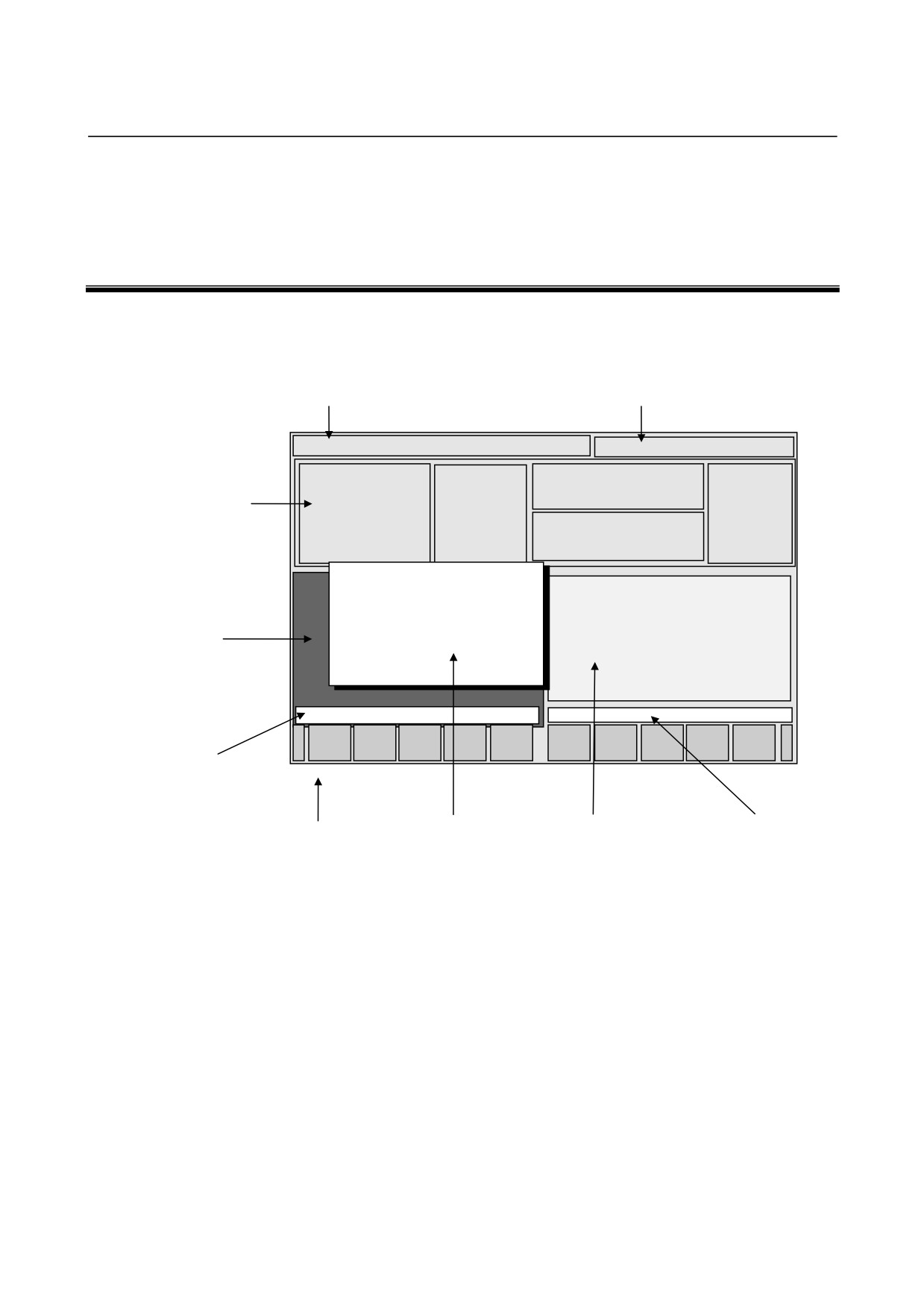
In MANUAL GUIDE i, basically, only one screen called the
All-in-one Screen is used for all the operations from trial machining to
actual machining.
Title area
CNC status area
MANUAL GUIDE i
ACTUAL POS
DIST TO GO
SPINDLE
Program
number etc.
Status indicator window
FEED
MM/MIN
PROGRAM
Graphic window
Message
window
Key-in buffer
Soft keys
Pop-up window
Program window
Title area:
The title of MANUAL GUIDE i is always displayed.
CNC status area:
The following CNC statuses are displayed.
•
Mode
•
Alarm status
•
Reset or emergency stop status
•
Actual time
Status indicator window:
The following information about CNC is displayed.
•
Actual machine position
•
Remaining moving distance of the actual block
- 9 -
3.ALL-IN-ONE SCREEN
GENERAL
B-63874EN/05
•
Actual speed and load meter
(for the axis with the
maximum load)
Remark) It is possible to display Actual speed in Feed per
revolution. ( Refer to the parameter No.14703#0. )
•
Spindle rotating speed and spindle load meter
•
Program number and process number
•
Command values during automatic operation (M,S,T,F)
Graphic window:
The following graphical drawing is displayed as needed.
•
Animated drawing with a solid model
(machining
simulation)
•
Tool path drawing
Program window:
The machining program is displayed.
Pop-up window:
The following supplemental screens are displayed as needed.
•
M-code menu
•
Fixed format statement menu
•
Set data (workpiece coordinate system, tool offset, fixed
format statement registration)
•
Program list
•
Data input window for machining cycles
Key-in buffer:
Comments on data and input numerical data are displayed as
needed.
Message window:
The following messages are displayed as needed.
•
Meaning of the word which a cursor is allocated (Guidance
Message)
Remark) It is possible to display two Guidance Message of
M/T mode in the CNC for compound lathe.
(Refer to the parameter No.14703#2.)
•
Meaning of Machine Cycle which is executing
•
Content of Warning and Alarm
Soft keys :
The comments on the following soft-keys are displayed as
needed.
•
Editing operation menu
•
Machining cycle menu
•
Pop-up window menu
- 10 -
B-63874EN/05
GENERAL
3.ALL-IN-ONE SCREEN
Remark)
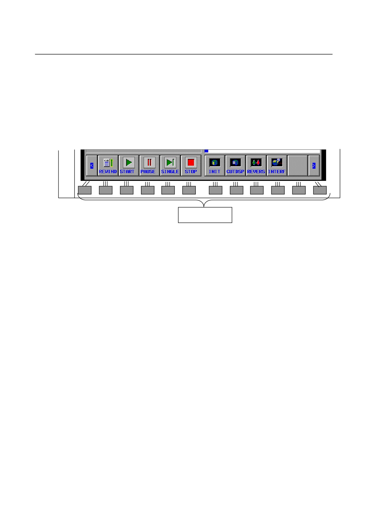
The soft keys described in this manual are specified to 12 keys
placed under the screen, LCD, as shown in the following
example.
The meaning of each soft key is various by the displayed content
on the screen, and will be displayed on the relevant part for each
key.
Example of soft keys)
Soft keys
- 11 -
///////////////////////////////////////