FANUC Series 16i/160i/160is-MODEL B, Series 18i/180i/180is-MODEL B, Series 21i/210i/210is-MODEL B. MAINTENANCE MANAUL - page 32

A. ALARM LIST
APPENDIX
B-63525EN/02
SPM in-
No.
Message
dica-
Faulty location and remedy
Description
tion(*1)
7n24
SPN_n_ : SERIAL
24
1
Place the CNC-to-spindle cable
The CNC power is turned off (normal
TRANSFER
away from the power cable.
power-off or broken cable).
ERROR
2
Replace the cable.
An error is detected in communica-
tion data transferred to the CNC.
7n26
SPN_n_ : DISCONNECT
26
1
Replace the cable.
The signal amplitude of the detection
C-VELO DE-
2
Re-adjust the pre-amplifier.
signal (connector JY2) on the Cs con-
TECT
tour control motor side is abnormal.
(Unconnected cable, adjustment er-
ror, etc.)
7n27
SPN_n_ : DISCONNECT
27
1
Replace the cable.
1
The spindle position coder (con-
POS-CODER
2
Re-adjust the BZ sensor signal.
nector JY4) signal is abnormal.
2
The signal amplitude (connector
JY2) of the MZ or BZ sensor is ab-
normal.
(Unconnected cable, adjustment
error, etc.)
7n28
SPN_n_ : DISCONNECT
28
1
Replace the cable
The position detection signal (con-
C-POS DE-
2
Re-adjust the pre-amplifier.
nector JY5) for Cs contour control is
TECT
abnormal.
(Unconnected cable, adjustment er-
ror, etc.)
7n29
SPN_n_ : SHORTTIME
29
Check and correct the load status.
Excessive load has been applied
OVERLOAD
continuously for a certain period of
time. (This alarm is issued also when
the motor shaft has been locked in the
excitation state.)
7n30
SPN_n_ : OVERCUR-
30
Check and correct the power supply
Overcurrent is detected in PSM main
RENT POW
voltage.
circuit input.
(PSM alarm indication:
CIRCUIT
1)
Unbalanced power supply.
PSM selection error (The maximum
PSM output specification is exceed-
ed.)
7n31
SPN_n_ : MOTOR LOCK
31
1
Check and correct the load status.
The motor cannot rotate at a specified
OR V-SIG LOS
2
Replace the motor sensor cable
speed.
(A level not exceeding the
(JY2 or JY5).
SST level for the rotation command
has existed continuously.)
Abnormality in the speed detection
signal.
7n32
SPN_n_ : RAM FAULT
32
Replace the SPM control printed cir-
Abnormality in an SPM control circuit
SERIAL LSI
cuit board.
component is detected. (The LSI de-
vice for serial transfer is abnormal.)
7n33
SPN_n_ : SHORTAGE
33
1
Check and correct the power sup-
Charging of direct current power sup-
POWER
ply voltage.
ply voltage in the power circuit section
CHARGE
2
Replace the PSM unit.
is insufficient when the magnetic con-
tractor in the amplifier is turned on
(such as open phase and defective
charging resistor).
902

B-63525EN/02
APPENDIX
A. ALARM LIST
SPM in-
No.
Message
dica-
Faulty location and remedy
Description
tion(*1)
7n34
SPN_n_ : PARAMETER
34
Correct a parameter value according
Parameter data exceeding the allow-
SETTING ER-
to the manual.
able limit is set.
ROR
If the parameter number is unknown,
connect the spindle check board, and
check the indicated parameter.
7n35
SPN_n_ : EX SETTING
35
Correct the value according to the pa-
Gear ratio data exceeding the allow-
GEAR RATIO
rameter manual.
able limit is set.
7n36
SPN_n_ : OVERFLOW
36
Check whether the position gain val-
An error counter overflow occurred.
ERROR
ue is too large, and correct the value.
COUNTER
7n37
SPN_n_ : SPEED DE-
37
Correct the value according to the pa-
The setting of the parameter for the
TECT PAR. ER-
rameter manual.
number of pulses in the speed detec-
ROR
tor is incorrect.
7n39
SPN_n_ :
1-ROT Cs SIG-
39
1
Adjust the 1-rotation signal in the
An incorrect relationship between the
NAL ERROR
pre-amplifier.
1-rotation signal and the number of
2
Check the cable shield status.
AB phase pulses was detected dur-
3
Replace the cable.
ing Cs contour control.
7n40
SPN_n_ : NO 1-ROT Cs
40
1
Adjust the 1-rotation signal in the
The 1-rotation signal is not gener-
SIGNAL DE-
pre-amplifier.
ated during Cs contour control.
TECT
2
Check the cable shield status.
3
Replace the cable.
7n41
SPN_n_ :
1-ROT POS-
41
1
Check and correct the parameter.
1
The
1-rotation signal of the
CODER ER-
2
Replace the cable.
spindle position coder (connector
ROR
3
Re-adjust the BZ sensor signal.
JY4) is abnormal.
2
The 1-rotation signal (connector
JY2) of the MZ or BZ sensor is ab-
normal.
3
Parameter setting error
7n42
SPN_n_ : NO 1-ROT.
42
1
Replace the cable.
1
The
1-rotation signal of the
POS-CODER
2
Re-adjust the BZ sensor signal.
spindle position coder (connector
DETECT
JY4) is disconnected.
2
The 1-rotation signal (connector
JY2) of the MZ or BZ sensor is dis-
connected.
7n43
SPN_n_ : DISCON. PC
43
Replace the cable.
The differential speed position coder
FOR DIF. SP.
signal (connector JY8) in SPM type 3
MODE
is abnormal.
7n44
SPN_n_ : CONTROL
44
Replace the SPM control printed cir-
Abnormality in an SPM control circuit
CIRCUIT(AD)
cuit board.
component was detected (A/D con-
ERROR
verter abnormality).
7n46
SPN_n_ : SCREW
46
1
Check and correct the parameter.
An abnormality equivalent to alarm
1-ROT POS-
2
Replace the cable.
41 was detected during thread cutting
COD. ALARM
3
Re-adjust the BZ sensor signal.
operation.
903

A. ALARM LIST
APPENDIX
B-63525EN/02
SPM in-
No.
Message
dica-
Faulty location and remedy
Description
tion(*1)
7n47
SPN_n_ : POS-CODER
47
1
Replace the cable.
1
The A/B phase signal of the
SIGNAL AB-
2
Re-adjust the BZ sensor signal.
spindle position coder (connector
NORMAL
3
Correct the cable layout (vicinity of
JY4) is abnormal.
the power line).
2
The A/B phase signal (connector
JY2) of the MZ or BZ sensor is ab-
normal.
The relationship between the A/B
phase and 1-rotation signal is incor-
rect (Pulse interval mismatch).
7n49
SPN_n_ : HIGH CONV.
49
Check whether the calculated differ-
In differential speed mode, the speed
DIF. SPEED
ential speed value exceeds the maxi-
of the other spindle converted to the
mum motor speed.
speed of the local spindle has ex-
ceeded the allowable limit (the differ-
ential speed is calculated by multiply-
ing the speed of the other spindle by
the gear ratio).
7n50
SPN_n_ : SPNDL CON-
50
Check whether the calculated value
In spindle synchronization, the speed
TROL OVER-
exceeds the maximum motor speed.
command calculation value exceed-
SPEED
ed the allowable limit
(the motor
speed is calculated by multiplying the
specified spindle speed by the gear
ratio).
7n51
SPN_n_ : LOW VOLT DC
51
1
Check and correct the power sup-
Input voltage drop was detected.
LINK
ply voltage.
(PSM alarm indication: 4) (Momen-
2
Replace the MC.
tary power failure or poor MC contact)
7n52
SPN_n_ : ITP SIGNAL
52
1
Replace the SPM control printed
NC interface abnormality was de-
ABNORMAL I
circuit board.
tected (the ITP signal stopped).
2
Replace the spindle interface
printed circuit board in the CNC.
7n53
SPN_n_ : ITP SIGNAL
53
1
Replace the SPM control printed
NC interface abnormality was de-
ABNORMAL II
circuit board.
tected (the ITP signal stopped).
2
Replace the spindle interface
printed circuit board in the CNC.
7n54
SPN_n_ : OVERLOAD
54
Review the load state.
An overload current was detected.
CURRENT
7n55
SPN_n_ : POWER LINE
55
1
Replace the magnetic contactor.
The power line state signal of the
SWITCH ER-
2
Check and correct the sequence.
magnetic contactor for selecting a
ROR
spindle or output is abnormal.
7n56
SPN_n_ : INNER COOL-
56
Replace the SPM unit.
The cooling fan in the SPM control cir-
ING FAN STOP
cuit stopped.
7n57
SPN_n_ : EX DECEL-
57
1
Decrease the acceleration/decel-
An overload was detected in the re-
ERATION
eration duty.
generative resistance. (PSMR alarm
POWER
2
Check the cooling condition (pe-
indication: 8)
ripheral temperature).
Thermostat operation or short-time
3
If the cooling fan stops, replace the
overload was detected.
resistor.
The regenerative resistor was dis-
4
If the resistance is abnormal, re-
connected, or an abnormal resis-
place the resistor.
tance was detected.
904

B-63525EN/02
APPENDIX
A. ALARM LIST
SPM in-
No.
Message
dica-
Faulty location and remedy
Description
tion(*1)
7n58
SPN_n_ : OVERLOAD IN
58
1
Check the PSM cooling status.
The temperature of the radiator of the
PSM
2
Replace the PSM unit.
PSM has increased abnormally.
(PSM alarm indication: 3)
7n59
SPN_n_ : COOLING FAN
59
Replace the SPM unit.
The cooling fan in the PSM stopped.
STOP IN PSM
(PSM alarm indication: 2)
7n62
SPN_n_ : MOTOR VCMD
62
Check and correct the parameters.
The specified motor speed is too
OVERFLOWED
(No. 4021, 4056 to 4059)
large.
7n66
SPN_n_ : AMP MODULE
66
1
Replace the cable.
An error was found in communication
COMMUNICA-
2
Check and correct the connection.
between amplifiers.
TION
7n73
SPN_n_ : MOTOR SEN-
73
1
Replace the feedback cable.
The motor sensor feedback signal is
SOR DISCON-
2
Check the shield processing.
not present.
NECTED
3
Check and correct the connection.
4
Adjust the sensor.
7n74
SPN_n_ : CPU TEST ER-
74
Replace the SPM control printed-cir-
An error was detected in a CPU test.
ROR
cuit board.
7n75
SPN_n_ : CRC ERROR
75
Replace the SPM control printed-cir-
An error was detected in a CRC test.
cuit board.
7n79
SPN_n_ : INITIAL TEST
79
Replace the SPM control printed-cir-
An error was detected in an initial test
ERROR
cuit board.
operation.
7n81
SPN_n_ :
1-ROT MO-
81
1
Check and correct the parameter.
The one-rotation signal of the motor
TOR SENSOR
2
Replace the feedback cable.
sensor cannot be correctly detected.
ERROR
3
Adjust the sensor.
7n82
SPN_n_ : NO 1-ROT
82
1
Replace the feedback cable.
The one-rotation signal of the motor
MOTOR SEN-
2
Adjust the sensor.
sensor is not generated.
SOR
7n83
SPN_n_ : MOTOR SEN-
83
1
Replace the feedback cable.
An irregularity was detected in a mo-
SOR SIGNAL
2
Adjust the sensor.
tor sensor feedback signal.
ERROR
7n84
SPN_n_ : SPNDL SEN-
84
1
Replace the feedback cable.
The spindle sensor feedback signal is
SOR DISCON-
2
Check the shield processing.
not present.
NECTED
3
Check and correct the connection.
4
Check and correct the parameter.
5
Adjust the sensor.
7n85
SPN_n_ :
1-ROT SPNDL
85
1
Check and correct the parameter.
The one-rotation signal of the spindle
SENSOR ER-
2
Replace the feedback cable.
sensor cannot be correctly detected.
ROR
3
Adjust the sensor.
7n86
SPN_n_ : NO 1-ROT
86
1
Replace the feedback cable.
The one-rotation signal of the spindle
SPNDL SEN-
2
Adjust the sensor.
sensor is not generated.
SOR ERROR
7n87
SPN_n_ : SPNDL SEN-
87
The one-rotation signal of the spindle
An irregularity was detected in a
SOR SIGNAL
sensor is not generated.
spindle sensor feedback signal.
ERROR
905
A. ALARM LIST
APPENDIX
B-63525EN/02
SPM in-
No.
Message
dica-
Faulty location and remedy
Description
tion(*1)
7n88
SPN_n_ : COOLING RA-
88
Replace the SPM external cooling
The external cooling fan stopped.
DIFAN FAIL-
fan.
URE
7n97
SPN_n_ : OTHER
97
Replace the SPM.
Another irregularity was detected.
SPINDLE
ALARM
7n98
SPN_n_ : OTHER CON-
98
Check the PSM alarm display.
A PSM alarm was detected.
VERTER
ALARM
SPM in-
No.
Message
dica-
Faulty location and remedy
Description
tion(*1)
9001
SPN_n_ : MOTOR OVER-
01
1
Check and correct the peripheral
The thermostat embedded in the mo-
HEAT
temperature and load status.
tor winding operated.
2
If the cooling fan stops, replace it.
The internal temperature of the motor
exceeds the specified level.
The motor is used in excess of the
continuous rating, or the cooling com-
ponent is abnormal.
9002
SPN_n_ : EX SPEED ER-
02
1
Check and correct the cutting
The motor speed cannot follow a spe-
ROR
conditions to decrease the load.
cified speed.
2
Correct parameter No. 4082.
An excessive motor load torque is de-
tected.
The acceleration/deceleration time in
parameter No. 4082 is insufficient.
9003
SPN_n_ : FUSE ON DC
03
1
Replace the SPM unit.
The PSM becomes ready (00 is indi-
LINK BLOWN
2
Check the motor insulation status.
cated), but the DC link voltage is too
3
Replace the interface cable.
low in the SPM.
The fuse in the DC link section in the
SPM is blown. (The power device is
damaged or the motor is ground-
fault.)
The JX1A/JX1B connection cable is
abnormal.
9006
SPN_n_ : THERMAL
06
1
Check and correct the parameter.
The temperature sensor of the motor
SENSOR DIS-
2
Replace the feedback cable.
is disconnected.
CONNECT
9007
SPN_n_ : OVERSPEED
07
Check for a sequence error. (For ex-
The motor speed has exceeded
ample, check whether spindle syn-
115% of its rated speed.
chronization was specified when the
When the spindle axis was in position
spindle could not be turned.)
control mode, positional deviations
were accumulated excessively (SFR
and SRV were turned off during
spindle synchronization.)
9009
SPN_n_ : OVERHEAT
09
1
Improve the heat sink cooling sta-
Abnormal temperature rise of the
MAIN CIRCUIT
tus.
power transistor radiator
2
If the heat sink cooling fan stops,
replace the SPM unit.
906

B-63525EN/02
APPENDIX
A. ALARM LIST
SPM in-
No.
Message
dica-
Faulty location and remedy
Description
tion(*1)
9011
SPN_n_ : OVERVOLT
11
1
Check the selected PSM.
Overvoltage of the DC link section of
POW CIRCUIT
2
Check the input power voltage and
the PSM was detected. (PSM alarm
change in power during motor de-
indication: 7)
celeration. If the voltage exceeds
PSM selection error. (The maximum
253 VAC (for the 200-V system) or
output specification of the PSM is ex-
530 VAC (for the 400-V system),
ceeded.)
improve the power supply imped-
ance.
9012
SPN_n_ : OVERCUR-
12
1
Check the motor insulation status.
The motor output current is abnormal-
RENT POW
2
Check the spindle parameters.
ly high.
CIRCUIT
3
Replace the SPM unit.
A motor-specific parameter does not
match the motor model.
Poor motor insulation
9015
SPN_n_ : SP SWITCH
15
1
Check and correct the ladder se-
The switch sequence in spindle
CONTROL
quence.
switch/output switch operation is ab-
ALARM
2
Replace the switching MC.
normal.
The switching MC contact status
check signal and command do not
match.
9016
SPN_n_ : RAM FAULT
16
Replace the SPM control printed cir-
Abnormality in an SPM control circuit
cuit board.
component is detected. (RAM for ex-
ternal data is abnormal.)
9018
SPN_n_ : SUMCHECK
18
Replace the SPM control printed cir-
Abnormality in an SPM control circuit
ERROR PGM
cuit board.
component is detected.
(Program
DATA
ROM data is abnormal.)
9019
SPN_n_ : EX OFFSET
19
Replace the SPM unit.
Abnormality in an SPM component is
CURRENT U
detected. (The initial value for the U
phase current detection circuit is ab-
normal.)
9020
SPN_n_ : EX OFFSET
20
Replace the SPM unit.
Abnormality in an SPM component is
CURRENT V
detected.
(The initial value of the V
phase current detection circuit is ab-
normal.)
9021
SPN_n_ : POS SENSOR
21
Check and correct the parameters.
The polarity parameter setting of the
POLARITY ER-
(No. 4000#0, 4001#4)
position sensor is wrong.
ROR
9024
SPN_n_ : SERIAL
24
1
Place the CNC-to-spindle cable
The CNC power is turned off (normal
TRANSFER
away from the power cable.
power-off or broken cable).
ERROR
2
Replace the cable.
An error is detected in communica-
tion data transferred to the CNC.
9027
SPN_n_ : DISCONNECT
27
1
Replace the cable.
1
The spindle position coder (con-
POS-CODER
2
Re-adjust the BZ sensor signal.
nector JY4) signal is abnormal.
2
The signal amplitude (connector
JY2) of the MZ or BZ sensor is ab-
normal.
(Unconnected cable, adjustment
error, etc.)
907

A. ALARM LIST
APPENDIX
B-63525EN/02
SPM in-
No.
Message
dica-
Faulty location and remedy
Description
tion(*1)
9029
SPN_n_ : SHORTTIME
29
Check and correct the load status.
Excessive load has been applied
OVERLOAD
continuously for a certain period of
time. (This alarm is issued also when
the motor shaft has been locked in the
excitation state.)
9030
SPN_n_ : OVERCUR-
30
Check and correct the power supply
Overcurrent is detected in PSM main
RENT POW
voltage.
circuit input.
(PSM alarm indication:
CIRCUIT
1)
Unbalanced power supply.
PSM selection error (The maximum
PSM output specification is exceed-
ed.)
9031
SPN_n_ : MOTOR LOCK
31
1
Check and correct the load status.
The motor cannot rotate at a specified
OR V-SIG LOS
2
Replace the motor sensor cable
speed.
(A level not exceeding the
(JY2 or JY5).
SST level for the rotation command
has existed continuously.)
Abnormality in the speed detection
signal.
9032
SPN_n_ : RAM FAULT
32
Replace the SPM control printed cir-
Abnormality in an SPM control circuit
SERIAL LSI
cuit board.
component is detected. (The LSI de-
vice for serial transfer is abnormal.)
9033
SPN_n_ : SHORTAGE
33
1
Check and correct the power sup-
Charging of direct current power sup-
POWER
ply voltage.
ply voltage in the power circuit section
CHARGE
2
Replace the PSM unit.
is insufficient when the magnetic con-
tractor in the amplifier is turned on
(such as open phase and defective
charging resistor).
9034
SPN_n_ : PARAMETER
34
Correct a parameter value according
Parameter data exceeding the allow-
SETTING ER-
to the manual.
able limit is set.
ROR
If the parameter number is unknown,
connect the spindle check board, and
check the indicated parameter.
9035
SPN_n_ : EX SETTING
35
Correct the value according to the pa-
Gear ratio data exceeding the allow-
GEAR RATIO
rameter manual.
able limit is set.
9036
SPN_n_ : OVERFLOW
36
Check whether the position gain val-
An error counter overflow occurred.
ERROR
ue is too large, and correct the value.
COUNTER
9037
SPN_n_ : SPEED DE-
37
Correct the value according to the pa-
The setting of the parameter for the
TECT PAR. ER-
rameter manual.
number of pulses in the speed detec-
ROR
tor is incorrect.
9041
SPN_n_ :
1-ROT POS-
41
1
Check and correct the parameter.
1
The
1-rotation signal of the
CODER ER-
2
Replace the cable.
spindle position coder (connector
ROR
3
Re-adjust the BZ sensor signal.
JY4) is abnormal.
2
The 1-rotation signal (connector
JY2) of the MZ or BZ sensor is ab-
normal.
3
Parameter setting error
908

B-63525EN/02
APPENDIX
A. ALARM LIST
SPM in-
No.
Message
dica-
Faulty location and remedy
Description
tion(*1)
9042
SPN_n_ : NO 1-ROT.
42
1
Replace the cable.
1
The
1-rotation signal of the
POS-CODER
2
Re-adjust the BZ sensor signal.
spindle position coder (connector
DETECT
JY4) is disconnected.
2
The 1-rotation signal (connector
JY2) of the MZ or BZ sensor is dis-
connected.
9043
SPN_n_ : DISCON. PC
43
Replace the cable.
The differential speed position coder
FOR DIF. SP.
signal (connector JY8) in SPM type 3
MODE
is abnormal.
9046
SPN_n_ : SCREW
46
1
Check and correct the parameter.
An abnormality equivalent to alarm
1-ROT POS-
2
Replace the cable.
41 was detected during thread cutting
COD. ALARM
3
Re-adjust the BZ sensor signal.
operation.
9047
SPN_n_ : POS-CODER
47
1
Replace the cable.
1
The A/B phase signal of the
SIGNAL AB-
2
Re-adjust the BZ sensor signal.
spindle position coder (connector
NORMAL
3
Correct the cable layout (vicinity of
JY4) is abnormal.
the power line).
2
The A/B phase signal (connector
JY2) of the MZ or BZ sensor is ab-
normal.
The relationship between the A/B
phase and 1-rotation signal is incor-
rect (Pulse interval mismatch).
9049
SPN_n_ : HIGH CONV.
49
Check whether the calculated differ-
In differential speed mode, the speed
DIF. SPEED
ential speed value exceeds the maxi-
of the other spindle converted to the
mum motor speed.
speed of the local spindle has ex-
ceeded the allowable limit (the differ-
ential speed is calculated by multiply-
ing the speed of the other spindle by
the gear ratio).
9050
SPN_n_ : SPNDL CON-
50
Check whether the calculated value
In spindle synchronization, the speed
TROL OVER-
exceeds the maximum motor speed.
command calculation value exceed-
SPEED
ed the allowable limit
(the motor
speed is calculated by multiplying the
specified spindle speed by the gear
ratio).
9051
SPN_n_ : LOW VOLT DC
51
1
Check and correct the power sup-
Input voltage drop was detected.
LINK
ply voltage.
(PSM alarm indication: 4) (Momen-
2
Replace the MC.
tary power failure or poor MC contact)
9052
SPN_n_ : ITP SIGNAL
52
1
Replace the SPM control printed
NC interface abnormality was de-
ABNORMAL I
circuit board.
tected (the ITP signal stopped).
2
Replace the spindle interface
printed circuit board in the CNC.
9053
SPN_n_ : ITP SIGNAL
53
1
Replace the SPM control printed
NC interface abnormality was de-
ABNORMAL II
circuit board.
tected (the ITP signal stopped).
2
Replace the spindle interface
printed circuit board in the CNC.
9054
SPN_n_ : OVERLOAD
54
Review the load state.
An overload current was detected.
CURRENT
9055
SPN_n_ : POWER LINE
55
1
Replace the magnetic contactor.
The power line state signal of the
SWITCH ER-
2
Check and correct the sequence.
magnetic contactor for selecting a
ROR
spindle or output is abnormal.
909

A. ALARM LIST
APPENDIX
B-63525EN/02
SPM in-
No.
Message
dica-
Faulty location and remedy
Description
tion(*1)
9056
SPN_n_ : INNER COOL-
56
Replace the SPM unit.
The cooling fan in the SPM control cir-
ING FAN STOP
cuit stopped.
9057
SPN_n_ : EX DECEL-
57
1
Decrease the acceleration/decel-
An overload was detected in the re-
ERATION
eration duty.
generative resistance. (PSMR alarm
POWER
2
Check the cooling condition (pe-
indication: 8)
ripheral temperature).
Thermostat operation or short-time
3
If the cooling fan stops, replace the
overload was detected.
resistor.
The regenerative resistor was dis-
4
If the resistance is abnormal, re-
connected, or an abnormal resis-
place the resistor.
tance was detected.
9058
SPN_n_ : OVERLOAD IN
58
1
Check the PSM cooling status.
The temperature of the radiator of the
PSM
2
Replace the PSM unit.
PSM has increased abnormally.
(PSM alarm indication: 3)
9059
SPN_n_ : COOLING FAN
59
Replace the SPM unit.
The cooling fan in the PSM stopped.
STOP IN PSM
(PSM alarm indication: 2)
9066
SPN_n_ : AMP MODULE
66
1
Replace the cable.
An error was found in communication
COMMUNICA-
2
Check and correct the connection.
between amplifiers.
TION
9073
SPN_n_ : MOTOR SEN-
73
1
Replace the feedback cable.
The motor sensor feedback signal is
SOR DISCON-
2
Check the shield processing.
not present.
NECTED
3
Check and correct the connection.
4
Adjust the sensor.
9074
SPN_n_ : CPU TEST ER-
74
Replace the SPM control printed-cir-
An error was detected in a CPU test.
ROR
cuit board.
9075
SPN_n_ : CRC ERROR
75
Replace the SPM control printed-cir-
An error was detected in a CRC test.
cuit board.
9079
SPN_n_ : INITIAL TEST
79
Replace the SPM control printed-cir-
An error was detected in an initial test
ERROR
cuit board.
operation.
9081
SPN_n_ :
1-ROT MO-
81
1
Check and correct the parameter.
The one-rotation signal of the motor
TOR SENSOR
2
Replace the feedback cable.
sensor cannot be correctly detected.
ERROR
3
Adjust the sensor.
9082
SPN_n_ : NO 1-ROT
82
1
Replace the feedback cable.
The one-rotation signal of the motor
MOTOR SEN-
2
Adjust the sensor.
sensor is not generated.
SOR
9083
SPN_n_ : MOTOR SEN-
83
1
Replace the feedback cable.
An irregularity was detected in a mo-
SOR SIGNAL
2
Adjust the sensor.
tor sensor feedback signal.
ERROR
9084
SPN_n_ : SPNDL SEN-
84
1
Replace the feedback cable.
The spindle sensor feedback signal is
SOR DISCON-
2
Check the shield processing.
not present.
NECTED
3
Check and correct the connection.
4
Check and correct the parameter.
5
Adjust the sensor.
9085
SPN_n_ :
1-ROT SPNDL
85
1
Check and correct the parameter.
The one-rotation signal of the spindle
SENSOR ER-
2
Replace the feedback cable.
sensor cannot be correctly detected.
ROR
3
Adjust the sensor.
910

B-63525EN/02
APPENDIX
A. ALARM LIST
SPM in-
No.
Message
dica-
Faulty location and remedy
Description
tion(*1)
9086
SPN_n_ : NO 1-ROT
86
1
Replace the feedback cable.
The one-rotation signal of the spindle
SPNDL SEN-
2
Adjust the sensor.
sensor cannot be correctly detected.
SOR ERROR
9087
SPN_n_ : SPNDL SEN-
87
The one-rotation signal of the spindle
An irregularity was detected in a
SOR SIGNAL
sensor is not generated.
spindle sensor feedback signal.
ERROR
9088
SPN_n_ : COOLING RA-
88
Replace the SPM external cooling
The external cooling fan stopped.
DIFAN FAIL-
fan.
URE
9097
SPN_n_ : OTHER
Check the SPM alarm display.
Other spindle alarm
SPINDLE
ALARM
9098
SPN_n_ : OTHER CON-
Check the PSM alarm display.
Other converter alarm
VERTER
ALARM
9110
SPN_n_ : AMP COMMU-
b0
1
Replace the communication cable
Communication error between am-
NICATION ER-
between amplifier and module.
plifier and module
ROR
2
Replace the SPM or PSM control
printed circuit board.
9111
SPN_n_ : CONV.LOW
b1
Replace the PSM control printed cir-
Low converter control power supply
VOLT CON-
cuit board.
voltage (PSM indication = 6)
TROL
9112
SPN_n_ : CONV.EXDIS-
b2
1
Check the regenerative resis-
Excessive converter regenerative
CHARGE POW.
tance.
power (PSM indication = 8)
2
Check the motor selection.
3
Replace the PSM
9113
SPN_n_ : CONV.COOL-
b3
Replace the cooling fan.
Stopped cooling fan of the converter
ING FAN FAIL-
radiator (PSM indication = A)
URE
9120
SPN_n_ : COMMUNICA-
C0
1
Replace the communication cable
Communication data alarm
TION DATA ER-
between CNC and SPM.
ROR
2
Replace the SPM control printed
circuit board.
3
Replace the CNC side spindle in-
terface printed circuit board.
9121
SPN_n_ : COMMUNICA-
C1
1
Replace the communication cable
Communication data alarm
TION DATA ER-
between CNC and SPM.
ROR
2
Replace the SPM control printed
circuit board.
3
Replace the CNC side spindle in-
terface printed circuit board.
9122
SPN_n_ : COMMUNICA-
C2
1
Replace the communication cable
Communication data alarm
TION DATA ER-
between CNC and SPM.
ROR
2
Replace the SPM control printed
circuit board.
3
Replace the CNC side spindle in-
terface printed circuit board.
911
A. ALARM LIST
APPENDIX
B-63525EN/02
A.4
ERROR CODES
NOTE*1
(SERIAL SPINDLE)
Note that the meanings of the SPM indications differ
depending on which LED, the red or yellow LED, is on.
When the yellow LED is on, an error code is indicated with
a 2-digit number. The error code is not displayed on the
CNC screen.
When the red LED is on, the SPM indicates the number of
an alarm generated in the serial spindle.
³ See Appendix A.3, “Alarms (Serial Spindle).”
Errors Displayed on the α Series Spindle Amplifier
SPM
indica-
Faulty location and remedy
Description
tion(*1)
00
Check the *ESP and MRDY sequence. (For MRDY, pay
Although neither *ESP (emergency stop signal; there
attention to the parameter setting regarding the use of the
are two types of signals including the PMC signal and
MRDY signal (bit 0 of parameter No. 4001).)
PSM contact signal(*2)) nor MRDY (machine ready sig-
nal) is input, SFR (forward rotation signal)/SRF (reverse
rotation signal)/ORCM (orientation command) is input.
01
Check the spindle motor speed detector parameter (bits
When the spindle motor has a high-resolution magnet-
2, 1, and 0 of parameter No. 4011).
ic pulse coder (Cs sensor) (bits 6 and 5 of parameter
No. 4001 are set to 0 and 1, respectively), 128 /rev is
to be set for the speed detector (bits 2, 1, and 0 of pa-
rameter No. 4011 are set to 0, 0, and 1, respectively).
However, a value other than 128
/rev is set. In this
case, the motor is not excited.
02
Check the parameters for the detector for Cs contour
Although use of a high-resolution magnetic pulse cod-
control (bit 5 of parameter No. 4001 and bit 4 of parame-
er (bit 5 of parameter No. 4001 = 1) or use of the Cs con-
ter No. 4018).
tour control function by the sensor (bit 4 of parameter
No. 4018 = 1) is not set, a Cs control command is input.
In this case, the motor is not excited.
03
Check the position coder signal parameter (bit 2 of pa-
Although use of the position coder signal (bit 2 of pa-
rameter No. 4001).
rameter No. 4001 = 1) is not set, a servo mode (rigid tap-
ping, spindle positioning) or spindle synchronization
command is input. In this case, the motor is not excited.
04
Check the orientation software option.
Although the orientation option is not set, an orientation
command (ORCM) is input.
05
Check the spindle output switching software option and
Although the output switching option is not set, the low-
power line status signal (RCH).
speed winding is selected (RCH = 1).
06
Check the sequence (CON, SFR, SRV).
Although the Cs contour control mode is specified,
SFR/SRV is not input.
07
Check the sequence (SFR, SRV).
Although the servo mode (rigid tapping, spindle posi-
tioning) is specified, SFR/SRV is not input.
09
Check the sequence (SPSYC, SFR, SRV)
Although spindle synchronization mode is specified,
SFR/SRV is not input.
10
During execution of the C-axis control command, do not
Although Cs contour control mode is set, another op-
specify another operation mode. Before entering anoth-
eration mode (servo mode, spindle synchronization, or
er mode, cancel the Cs contour control command.
orientation) is specified.
11
During execution of the servo mode command, do not
Although servo mode (rigid tapping, or spindle position-
specify another operation mode. Before entering anoth-
ing) is set, another operation mode (Cs contour control,
er mode, cancel the servo mode.
spindle synchronization, or orientation) is specified.
912
B-63525EN/02
APPENDIX
A. ALARM LIST
SPM
indica-
Faulty location and remedy
Description
tion(*1)
12
During execution of the spindle synchronization com-
Although spindle synchronization is being performed,
mand, do not specify another operation mode. Before
another operation mode (Cs contour control, servo
entering another mode, cancel the spindle synchroniza-
mode, or orientation) is specified.
tion command.
13
During execution of the orientation command, do not
Although the orientation command is being executed,
specify another operation mode. Before entering anoth-
another operation mode (Cs contour control, servo
er mode, cancel the orientation command.
mode, or synchronization) is specified.
14
Input the SFT or SRV signal.
The SFT and SRV signals are both input at the same
time.
15
Check bit 5 of parameter No. 4000 and PMC signal
When bit 5 of parameter No. 4000 is set to 1 to indicate
(CON).
the presence of the differential speed mode function,
Cs contour control is specified.
16
Check bit 5 of parameter No. 4000 and PMC signal
When bit 5 of parameter No. 4000 is set to 0 to indicate
(DEFMD).
the absence of the differential speed mode function, the
differential speed mode command (DEFMD) is input.
17
Check bits 2, 1, and 0 of parameter No. 4011.
Setting of the speed detector parameter (bits 2, 1, and
0 of parameter No. 4011) is invalid. (The corresponding
speed detector is not present.)
18
Check bit 2 of parameter No. 4001 and PMC signal
Although bits 2 of parameter No. 4001 is set to 0 not to
(ORCM).
use the position coder signal, a command for orienta-
tion by a position coder (ORCMA) is input.
19
During execution of the orientation command, do not
Although orientation by a magnetic sensor is being per-
specify another operation mode. Before entering anoth-
formed, another operation mode is specified.
er mode, cancel the orientation command.
20
Check bit 5 of parameter No. 4001, bit 5 of parameter No.
When the use of the slave operation mode function is
4014, and bit 4 of parameter No. 4018.
set (bit 5 of parameter No. 4014 = 1), the use of a high-
resolution magnetic pulse coder (bit 5 of parameter No.
4001 = 1) or the use of the Cs contour control function
by the sensor (bit 4 of parameter No. 4018 = 1) is speci-
fied. These items cannot be set at the same time.
21
Input the slave operation mode command (SLV) in nor-
Although position control (such as servo mode or
mal operation mode.
orientation) is being performed, a slave operation mode
command (SLV) is input.
22
Input the position control command in normal operation
Although slave operation mode is set (SLVS = 1), a
mode
position control command (such as servo mode or
orientation) is input.
23
Check bit 5 of parameter No. 4014 and PMC signal
Although bit 5 of parameter No. 4014 is set to 0 not to
(SLV).
use the slave operation mode function, a slave opera-
tion mode command (SLV) is input.
24
Check the PMC signal (INCMD). Perform orientation by
Orientation is performed in incremental operation mode
specifying an absolute position first.
(INCMD = 1) first, then the absolute position command
(INCMD = 0) is input.
25
Check the spindle amplifier specifications and parameter
Although the spindle amplifier SPM type 4 is not used,
setting (bit 4 of parameter No. 4018).
the use of the Cs contour control function by the sensor
is set (bit 4 of parameter No. 4018 = 1).
NOTE*2
PSM contact signal
Between ESP1 and ESP2 on the PSM
Contact open: Emergency stop
Contact closed: Normal operation
913
B. LIST OF MAINTENANCE PARTS
APPENDIX
B-63525EN/02
LIST OF MAINTENANCE PARTS
B
Item
Ordering information
Remarks
Fuse
LCD-mounted type control unit (without PC)
A02B-0236-K100
CNC display unit for is series CNC
LCD-mounted type is series control unit
A02B-0236-K101
Stand-alone type is series control unit
A02B-0265-K100
Stand-alone type LCD unit
A02B-0265-K101
Separate detector interface unit
A60L-0001-0290#LM20
Rated at 2 A
I/O module for operator’s panel
A03B-0815-K001
Connector panel I/O module
A03B-0815-K002
Distributed I/O machine operator’s panel
A60L-0001-0290#LM10
Interface unit of machine operator’s panel
A02B-0120-K107
Connection unit of operator’s panel
A02B-0163-K111
CNC display unit with PC functions and PANEL i (1) (*)
A02B-0236-K101
CNC display unit with PC functions and PANEL i (2) (*)
A08B-0082-K001
Battery
For control unit memory backup
A02B-0200-K102
For CNC display unit with PC functions and PANEL i
Fan motor for LCD-
For control unit with no expansion slot
A02B-0236-K120
mounted type
CNC display unit for is series CNC
For control unit with expansion slot
A02B-0281-K121
For control unit with three expansion slots
A02B-0236-K122
Fan unit for stand-
For 1-slot case
A02B-0265-C101
alone type CNC
For 2-slot case
A02B-0260-C021
Fan for CNC display
For main body
A08B-0082-K010
unit with PC functions
and PANEL i
For HDD
A13B-0178-K001
Backlight
For 7.2″ LCD
A02B-0236-K112
For 8.4″ LCD
A02B-0236-K119
For 9.5″ LCD
A02B-0281-K114
Touch panel protec-
For 10.4” LCD with touch panel
A02B-0236-K110
tion sheet
For 10.4” LCD with touch panel and soft key
A02B-0236-K130
For 12.1” LCD
A02B-0236-K118
For 15.0” LCD
A08B-0082-K020
Pen for touch panel
A02B-0236-K111
See Subsection 5.10.2 for a difference between (1)(*) and (2)(*).
914
B-63525EN/02
APPENDIX
C. BOOT SYSTEM
BOOT SYSTEM
C
C.1
OVERVIEW
916
C.2
SCREEN CONFIGURATION AND OPERATING
PROCEDURE
918
C.3
ERROR MESSAGES AND REQUIRED
ACTIONS
933
915
C. BOOT SYSTEM
APPENDIX
B-63525EN/02
The boot system load the CNC system software (flash RAM→DRAM),
C.1
then starts it so that software can be executed.
OVERVIEW
The boot system provides the following maintenance functions for the
CNC:
(1) Registering a file in flash ROM
⋅
Reads a file from a memory card, in FAT format, into flash ROM.
(2) Checking a file (series and edition) in flash ROM
(3) Deleting a file from flash ROM
(4) Batch saving and restoration of files of parameters and programs
backed up by battery (SRAM area), to and from a memory card
(5) Saving a file in flash ROM to a memory card
(6) Formatting of a memory card
(7) Deleting a file from a memory card
This manual describes the activation of the boot system, as well as the
screen displays and operation for the functions listed above.
CAUTION
This control unit supports the use of a memory card as an
input/output device. When a flash card is used, however,
data can be written to a FANUC-recommended card only.
Data can be read in the same way as with an ordinary SRAM
card, provided the data has been saved in FAT format. Note
that, when a flash card is used, the card capacity is reduced
by 128KB.
See the order list for details of the supported memory card
types.
C.1.1
In ordinary system activation, the boot system automatically transfers
files from flash ROM to DRAM in the background.
Starting the Boot
The user is not aware of this operation. However, the boot system must
System
be operated manually, from menu screen, when maintenance is to be
carried out or when the flash ROM does not contain a required file.
1
In system maintenance, for example, to replace a file in ROM
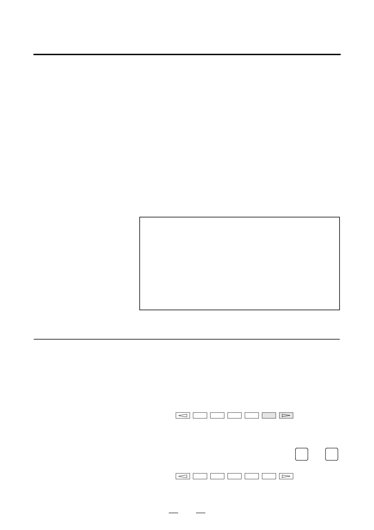
Operation : Turn the power on by simultaneously pressing the two soft
keys at the right end.
Hold down the two keys until the boot system screen appears.
If soft keys are not provided (for example, when a touch pad is being
used), use the MDI numeric keys. Hold down the
6
and
7
keys until the boot system screen appears.
±
±
±
±
±
±
±
1.
2.
3.
4.
5.
6.
7.
916
B-63525EN/02
APPENDIX
C. BOOT SYSTEM
2
When the flash memory does not contain a file required to start the
CNC
Immediately after the CNC is turned on, the boot system starts
transferring files from flash ROM to DRAM. If, for some reason, a
file required to start the CNC (NC basic) is not in flash ROM or has
been destroyed, the boot system is automatically started.
C.1.2
The boot system organizes files in flash ROM into two main groups :
system files and user files. These two file types have the following
System Files and User
characteristics :
Files
D System files
CNC and servo control software provided by FANUC
D User files
PMC sequence program (ladder), P-CODE macro program, and other
user-created files
C.1.3
When CAP-II board or LCB (loader control board) is mounted on the
CNC, we have to access to SRAM that mounted on additional board. So,
Boot Slot
the boot system displays BOOT SLOT CONFIGURATION screen that
Configuration Screen
to select a access board.
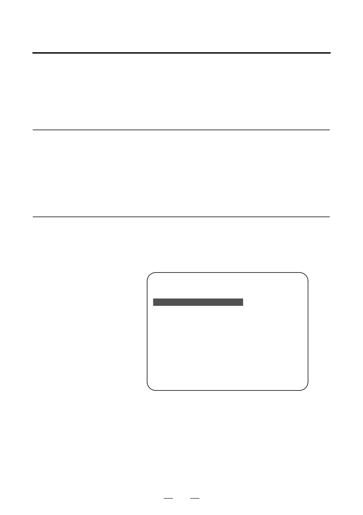
D Screen configuration
(1)
BOOT SLOT CONFIGURATION
60M5-01
NO. BOARD
F-ROM
SRAM
(2)
0. MAIN
16MB
1.0MB
1. PMC-RE
6MB
256KB
2. CAP-II
512KB
3. LCB
512KB
*** MESSAGE ***
(3)
SELECT SLOT AND HIT SELECT KEY.
[ SELECT ][ YES
][ NO
][ UP
][ DOWN
]
(1) : Screen title.
(2) : Flash memory size and SRAM size of each board.
(3) : Message
D Operation
Press the [ UP ] or [DOWN] soft key to move the cursor, and select board
to press the [SELECT] soft key.
917
C. BOOT SYSTEM
APPENDIX
B-63525EN/02
When the boot system is first started, the MAIN MENU screen is
C.2
displayed. This screen is described below :
SCREEN
CONFIGURATION
AND OPERATING
PROCEDURE
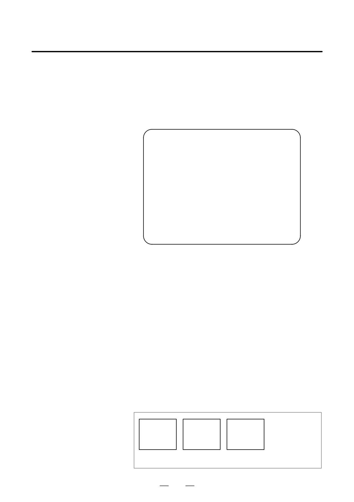
D MAIN MENU screen
(1)
SYSTEM MONITOR MAIN MENU
60M5-01
(2)
1. SYSTEM DATA LOADING
(3)
2. SYSTEM DATA CHECK
(4)
3. SYSTEM DATA DELETE
(5)
4. SYSTEM DATA SAVE
(6)
5. SRAM DATA BACKUP
(7)
6. MEMORY CARD FILE DELETE
(8)
7. MEMORY CARD FORMAT
(9)
10. END
*** MESSAGE ***
(10)
SELECT MENU AND HIT SELECT KEY.
[ SELECT ][ YES
][ NO
][ UP
][ DOWN
]
(1)
: Screen title. The series and edition of the boot system appear at
the right end.
(2)
: Function for writing data to flash ROM.
(3)
: Function for checing the edition of a file in ROM.
(4)
: Function for deleting a file from flash ROM.
(5)
: Function for making a backup copy of the data stored on the memory
card.
(6)
: Function for making a backup copy of the data in SRAM.
(7)
: Function for deleting a file from a memory card.
(8)
: Function for formatting a memory card.
(9)
: Function for terminating the boot system and starting the CNC.
(10) : Condensed guidance or error message
Press the [UP] or [DOWN] soft key to select the desired function. After
D Operating procedure
positioning the cursor to the desired function, press the [SELECT] soft
key. Before executing a function, the system my request confirmation
from the operator by having him/her press the [YES] or [NO] soft key.
D Basic operation
Position the
Select a
Check the
cursor.
function
selection
Execute
[UP]
→
[SELECT]
→
[YES]
→ the
→ Select END
[DOWN]
[NO]
function
→ Return to
original state
918
B-63525EN/02
APPENDIX
C. BOOT SYSTEM
C.2.1
System Data Loading
Screen
D Description
This screen is used to read a system or user file from a memory card into
flash ROM.
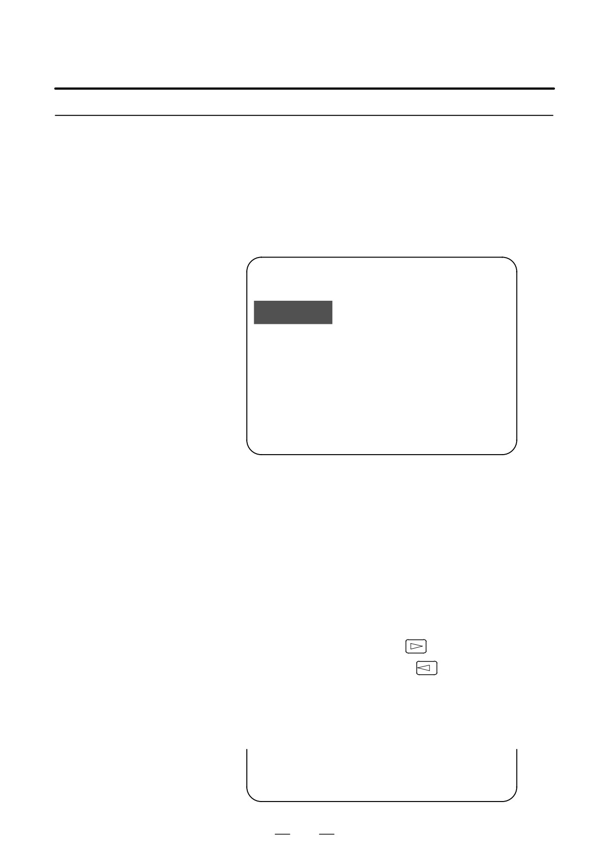
D Screen configuration
(1)
SYSTEM DATA LOADING
1/1
FILE DIRECTORY
(2)
B1H1A_B1.MEM
B1H1A_AI.MEM
(3)
END
*** MESSAGE ***
(4)
SELECT FILE AND HIT SELECT KEY.
[ SELECT ][ YES
][ NO
][ UP
][ DOWN
]
(1) : Screen title. The page number (n) and total number of pages (m)
are displayed, in n/m format, at the right end.
(2) : Files on the memory card
(3) : Option for returning to previous menu Message
(4) : Message
D Operating procedure
1
Position the cursor to the file to be read from the memory card and
written to flash ROM. Then, press the [SELECT] soft key.
A single page can list up to eight file names. If the memory card
contains nine or more files, the remaining files are displayed on
another page.
To display the next page, press the
soft key.
To display the previous page, press the
soft key. The END option
is displayed on the last page.
The END option is displayed on the last page.
2
After a file has been slected, the system asks whether that file is to be
loaded.
*** MESSAGE ***
LOADING OK ? HIT YES OR NO.
919
C. BOOT SYSTEM
APPENDIX
B-63525EN/02
3
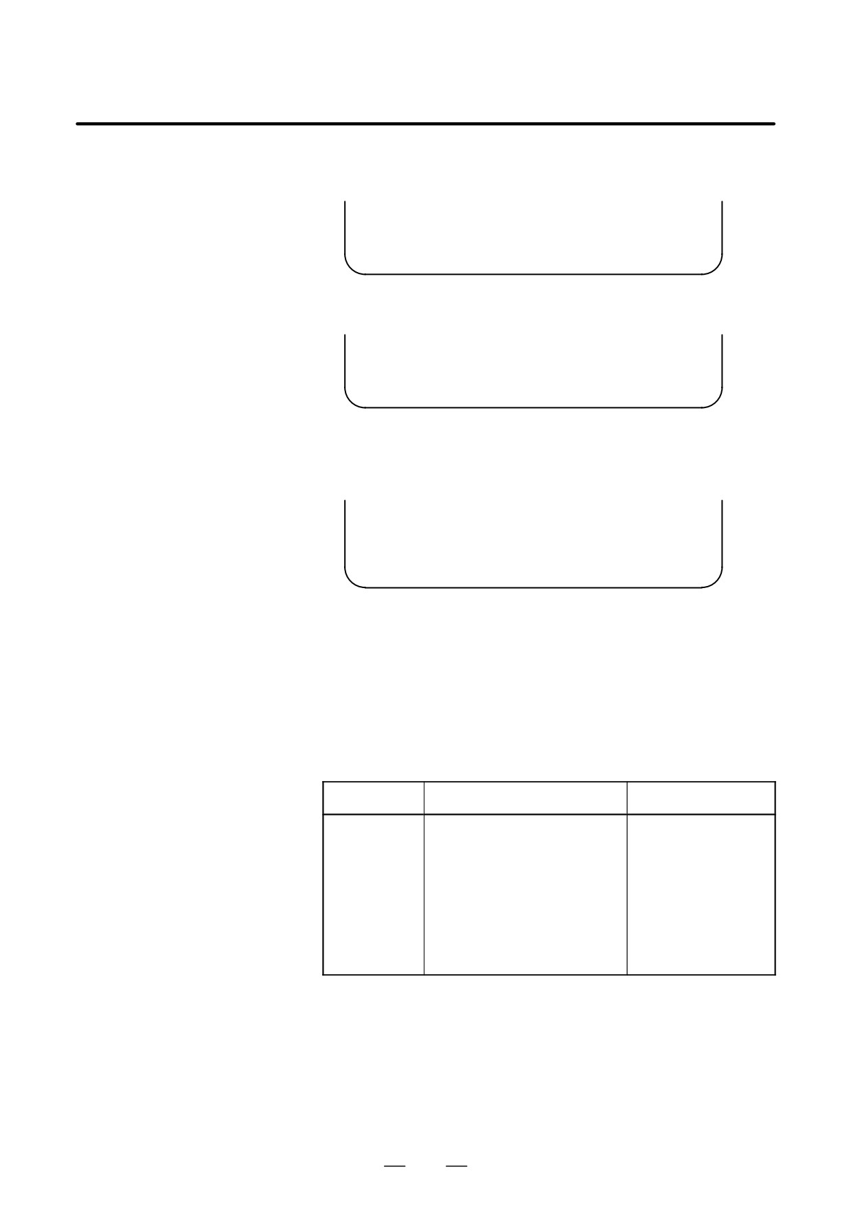
To start loading, press the [YES] soft key. To cancel, press the [NO]
key.
*** MESSAGE ***
LOADING FROM MEMORY CARD.
4
When loading terminates normally, the system displays the following
message. Press the [SELECT] soft key. If an error occurs, see C.3
*** MESSAGE ***
LOADING COMPELETE. HIT SELECT KEY.
D Others
1
Counter display while a file is being loaded
While a file is being loaded, the address of the data currently being
accessed is displayed.
*** MESSAGE ***
LOADING FROM MEMORY CARD.
ADDRESS 001:
² The counter appears under the
message fild.
(1)
(1) : Number of 128-KB management unit in flash ROM
2
File name in flash ROM
The boot system identifies a file in flash ROM by the first four
characters of the ID in the header. If flash ROM has a file of the same
type as a file to be read from the memory card, the file in flash ROM
is deleted before the file on the memory card is read. The following
table lists the IDs in the header and the contents. Note that these IDs
are subject to change without prior notice.
File name
Contents
File type
NC BASIC
Basic 1
System file
NC 2BSIC
Basic 2
System file
DGB0SRVO
Servo
System file
GRAPHIC
Graphic
System file
NCj OPTN
Optionalj
System file
PSj****
PMC control software, etc.
System file
ETH2 EMB
Embeddedethernet
System file
PCD ****
P-CODE macro file/ OMM
User file
CEX ****
C-language executor
User file
PMC - ****
Ladder software
User file
PMC@****
Ladder software for the loader
User file
V : A numeric character, *: An alphabetic character
920
B-63525EN/02
APPENDIX
C. BOOT SYSTEM
C.2.2
System Data Check
Screen
D Description
This screen is used to list files in flash ROM, together with the
corresponding numbers of 128-KB management units in each file and the
series and edition of the software.
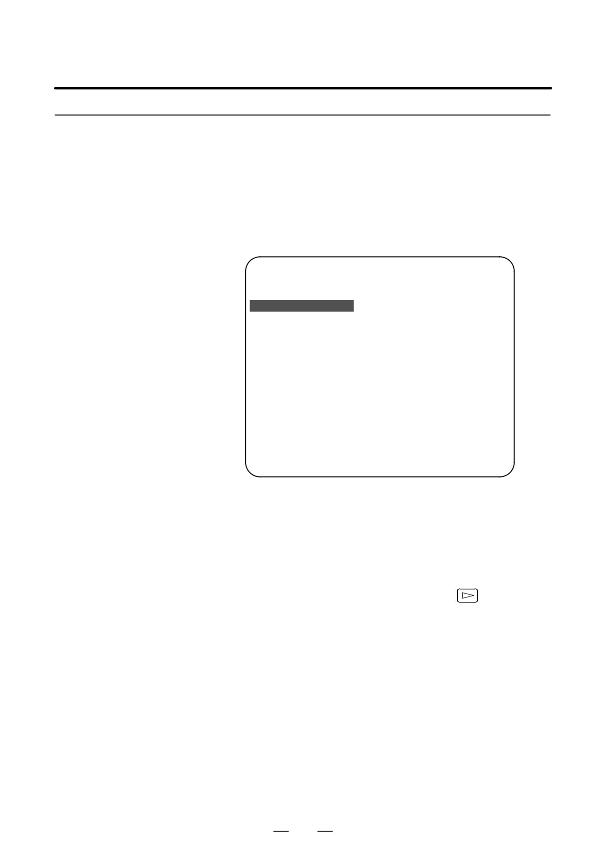
D Screen configuration
(1)
SYSTEM DATA CHECK
1/1
(2)
[BOARD:MAIN]
FILE DIRECTORY (FLASH ROM : 16MB)
(3)
1 NC BASIC
( 10)
2 NC2 BSIC
( 8)
3 DGB0SRVO
( 2)
4 PS0B406G
( 8)
5 PS1B406G
( 4)
(4)
6 PS2B406G
( 4)
7 ETH2 EMB
( 8)
END
(5)
*** MESSAGE ***
SELECT FILE AND HIT SELECT KEY.
[ SELECT ][ YES
][ NO
][ UP
][ DOWN
]
(1) : Screen title
(2) : Names of accessing board
(3) : Names of files in flash ROM The number of management units
constituting each file appears in parentheses to the right of the file
name.
(4) : Returning to the previous menu
If flash ROM contains many files, END is sometimes not displayed.
In this case, press the continuous menu key (
) of the soft key
display several times. Then, END appears at the end of files.
(5) : Message
921
C. BOOT SYSTEM
APPENDIX
B-63525EN/02
D Operating procedure
1
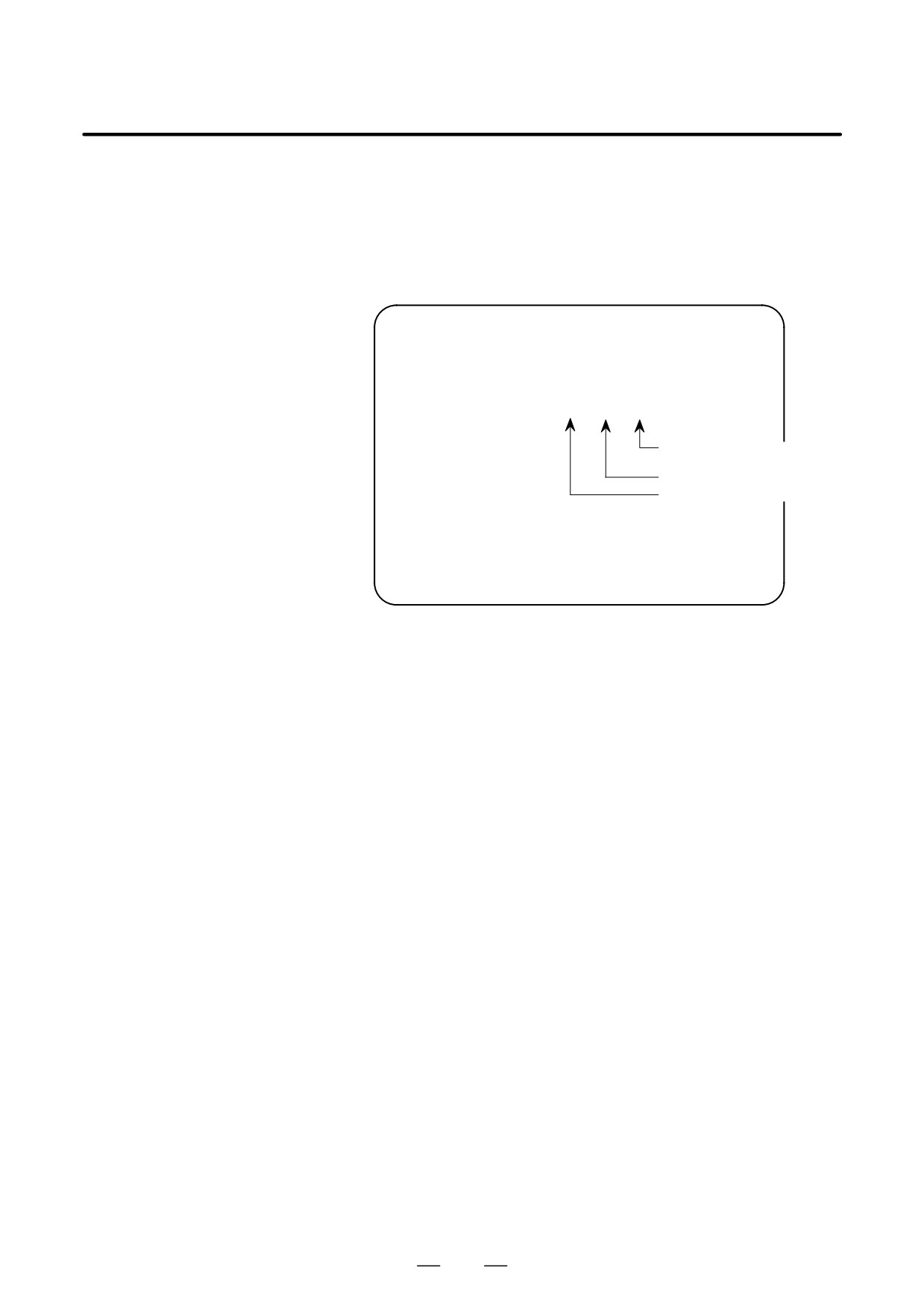
Select the file whose details are required. For example, select “1 NC
BASIC (10).”
2
The numbers of management units in the selected file are listed,
together with the series and edition of the software in each
management unit. After checking the listed data, select the
[SELECT] soft key to return to the file selection screen.
ROM FILE CHECK
NC BASIC
0 B1H1 801A 000
1 B1H1 821A 001
0 B1H1 801A 000
2 B1H1 841A 002
3 B1H1 861A 003
4 B1H1 881A 004
ÁInternal management-unitÁ
5 B1H1 8A1A 005
ÁnumberÁÁÁÁÁÁ
6 B1H1 8C1A 006
OM number and edition
Series
7 B1H1 8E1A 007
*** MESSAGE ***
HIT SELECT KEY.
D Others
Parity information for the system file and user file
The NC BASIC, DGB0SRVO, and other system files in flash ROM
contain parity information in each management unit. If the file name field
or parity field on the check screen contains a non-ASC II character or an
“@”, the flash ROM may have been destroyed or a damaged file may have
been read. Re-read the data from the memory card.
The PMC-SB, PCD 0.5M, and other user files do not contain parity
information in each management unit. A non-ASCII character or an “@”
may appear in the series/edition information. In this case, it does not
indicate that the file has been damaged.
922
B-63525EN/02
APPENDIX
C. BOOT SYSTEM
C.2.3
System Data Delete
Screen
D Description
This screen is used to delete a user file from flash ROM.
D Screen configuration
(1)
SYSTEM DATA CHECK
1/1
(2)
[BOARD:MAIN]
FILE DIRECTORY (FLASH ROM : 16MB)
(3)
1 NC BASIC
( 10)
2 NC2 BSIC
( 8)
3 DGB0SRVO
( 2)
4 PS0B406G
( 8)
5 PS1B406G
( 4)
(4)
6 PS2B406G
( 4)
7 ETH2 EMB
( 8)
END
(5)
*** MESSAGE ***
SELECT FILE AND HIT SELECT KEY.
[ SELECT ][ YES
][ NO
][ UP
][ DOWN
]
(1) : Screen title
(2) : Names of accessing board
(3) : Names of files in flash ROM The number of management units
constituting each file appears in parentheses to the right of the file
name.
(4) : Returning to the previous menu
If flash ROM contains many files, END is sometimes not displayed.
In this case, press the continuous menu key (
) of the soft key
display several times. Then, END appears at the end of files.
(5) : Message
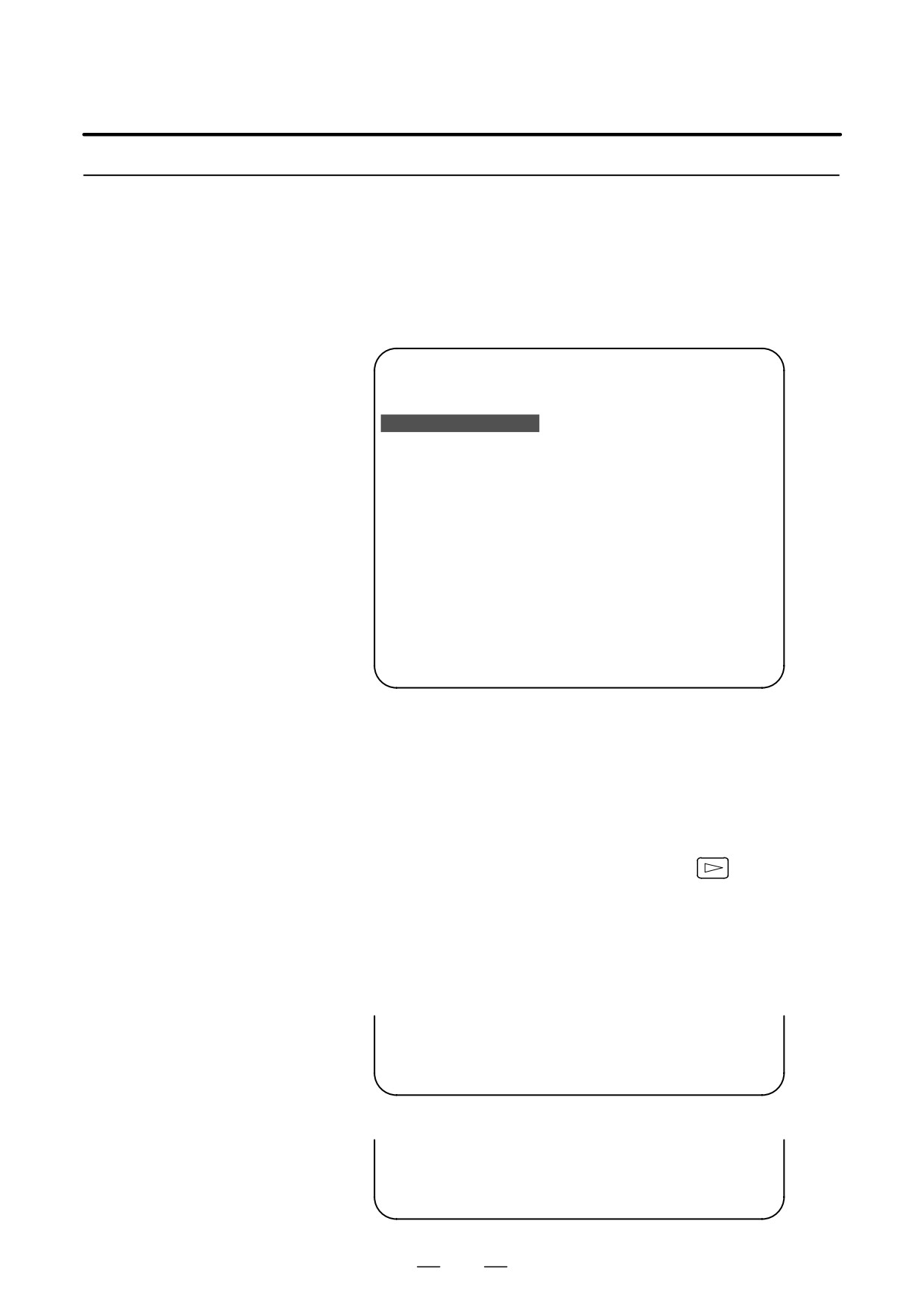
D Operating procedure
1
Position the cursor to the name of the file to be deleted. Press the
[SELECT] soft key.
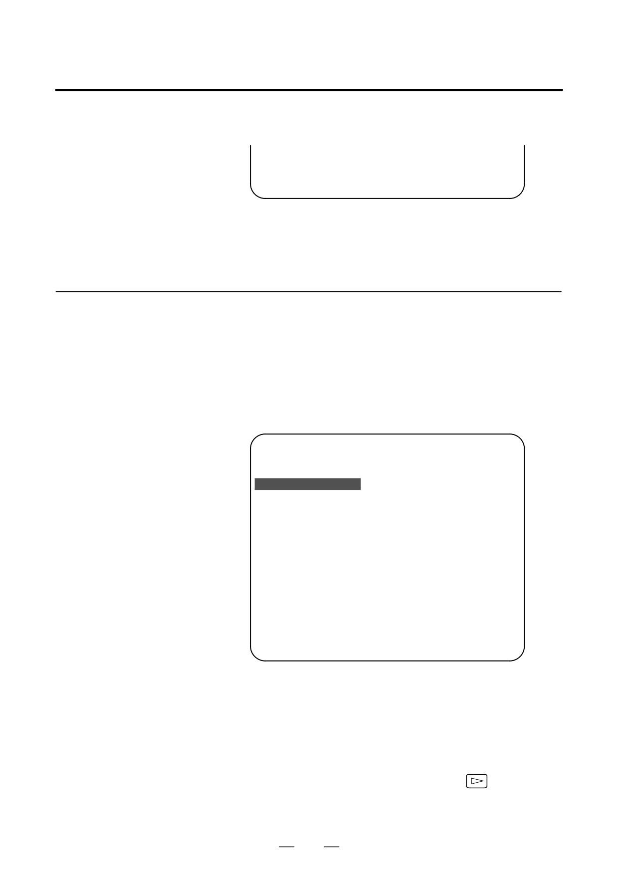
2
The system displays the following confirmation message :
*** MESSAGE ***
DELETE OK ? HIT YES OR NO.
3
To start the deletion, press the [YES] key. To cancel, press [NO].
*** MESSAGE ***
DELETING ROM FILE IN FLASH MEMORY.
923
C. BOOT SYSTEM
APPENDIX
B-63525EN/02
4
When deletion terminates normally, the system displays the following
message. Press the [SELECT] key.
*** MESSAGE ***
DELETING COMPLETE. HIT SELECT KEY.
D Others
1
System files and user files on SYSTEM DATA DELETE screen
The system files are protected from accidental deletion. User files,
however, are not protected. Protected system files can be
overwritten from the SYSTEM DATA LOADING screen.
C.2.4
SYSTEM DATA SAVE
Screen
D Description
This screen is used to write a user file in flash ROM to a memory card.
Only user files can be saved from flash ROM to a memory card. System
files cannot be saved.
D Screen configuration
(1)
SYSTEM DATA SAVE
(2)
[BOARD:MAIN]
FILE DIRECTORY (FLASH ROM : 16MB)
(3)
1 NC BASIC
( 10)
2 NC2 BSIC
( 8)
3 DGB0SRVO
( 2)
4 PS0B406G
( 8)
5 PS1B406G
( 4)
(4)
6 PS2B406G
( 4)
7 ETH2 EMB
( 8)
END
(5)
*** MESSAGE ***
SELECT FILE AND HIT SELECT KEY.
[ SELECT ][ YES
][ NO
][ UP
][ DOWN
]
(1) : Screen title
(2) : Names of accessing board
(3) : Names of files in flash memory The number of management units
constituting each file appears in parentheses to the right of the file
name.
(4) : Returning to the previous menu
If flash ROM contains many files, END is sometimes not displayed.
In this case, press the continuous menu key (
) of the soft key
display several times. Then, END appears at the end of files.
(5) : Message
924
B-63525EN/02
APPENDIX
C. BOOT SYSTEM
D Operating procedure
1
Position the cursor to the name of the file to be deleted. Press the
[SELECT] soft key.
2
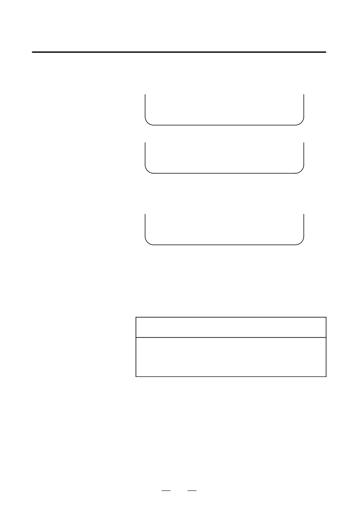
The system displays the following confirmation message :
*** MESSAGE ***
SAVE OK ? HIT YES OR NO.
3
To start saving, press the [YES] key. To cancel, press [NO].
*** MESSAGE ***
WRITING FLASH ROM FILE TO MEMORY CARD.
SAVE FILE NAME : PMC_RB.000
4
When saving terminates normally, the system displays the
following message. Press the [SELECT] key. The names of files
written to the memory card are listed. Check the file names by, for
example, making a note of the list.
*** MESSAGE ***
FILE SAVE COMPELETE. HIT SELECT KEY.
SAVE FILE NAME : PMC_RB.000
D Others
1
System files and user files on SYSTEM DATA SAVE screen
The SYSTEM DATA SAVE function provides a safeguard against free
copying of the system files.
User files, however, are not protected.
2
Names of saved files
Files saved from flash ROM to a memory card have the following
names :
Flash ROM
File name in
Memory card
PMC-SB
³
PMC_SB. XXX
PMC 0.5M
³
PCD_0.5M.XXX
PMC 1.0M
³
PCD_10M.XXX
PMC 1.5M
³
PCD_15M.XXX
CEX1.0M
³
CEX_10M.XXX
CEX 2.0M
³
CEX_20M.XXX
XXX corresponds to the file extension of MS-DOS format files. A
number from 000 to 031 is specified for XXX. For example, if the
PMC-RB file in flash ROM is saved to a memory card that does not yet
contain a file whose name begins with “PMC-RB”, the saved file is
named PMC-RB.000. If, however, that file is saved to a memory card that
already contains a file named PMC-RB.000, the saved file is named
PMC-RB.001. As files are added, the extension is incremented up to a
maximum of PMC-RB.031. Any no-longer used numbers in the
sequence of the extension numbers are used in as cending order. If two
or more files having identical names but different extension numbers are
normally saved to the memory card, check the file names displayed
subsequently.
925
C. BOOT SYSTEM
APPENDIX
B-63525EN/02
C.2.5
SRAM DATA BACKUP
Screen
D Description
This screen is used to collectively save and restore parameters, programs,
and other data, retained after the CNC power in SRAM is turned off, to
and from a memory card.
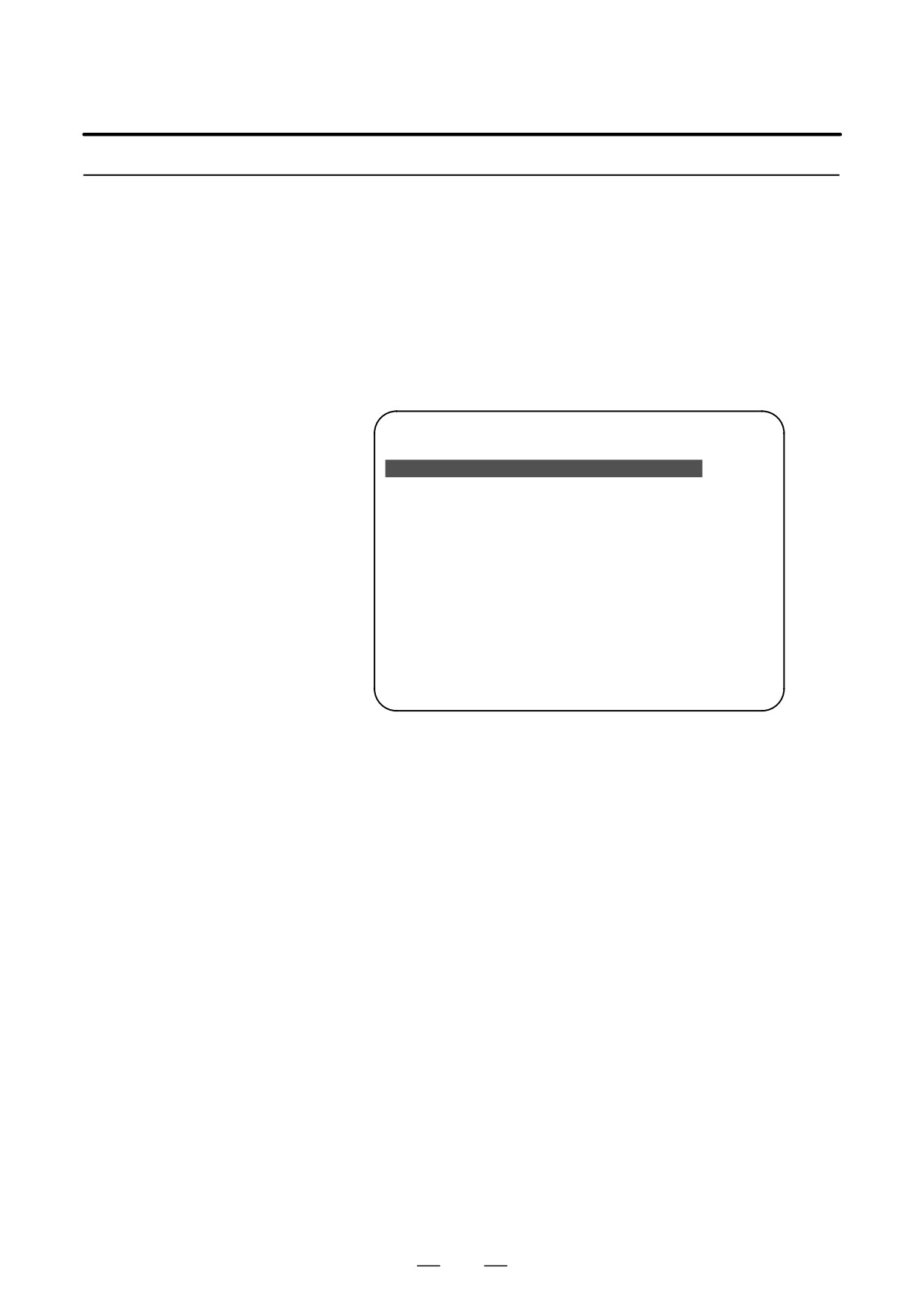
D Screen configuration
Select “4 SRAM DATA BACKUP” on the SYSTEM MONITOR MAIN
MENU screen. The following screen is displayed.
(1)
SRAM DATA BACKUP
(2)
[BOARD:MAIN]
(3)
1. SRAM BACKUP (CNC
³ MEMORY CARD)
2. RESTORE SRAM (MEMORY CARD
³ CNC)
(4)
END
(5)
SRAM SIZE
:
256K (BASIC)
(6)
FILE NAME
:
SRAM256A. FDB
*** MESSAGE ***
(7)
SELECT MENU AND HIT SELECT KEY.
[ SELECT ][ YES
][ NO
][ UP
][ DOWN
]
(1) : Screen title
(2) : Names of accessing board
(3) : Menu
(4) : Returning to the previous menu
(5) : Size of SRAM mounted on the CNC
(6) : File name
(7) : Message
926
B-63525EN/02
APPENDIX
C. BOOT SYSTEM
D Operating procedure
[Backing up data]
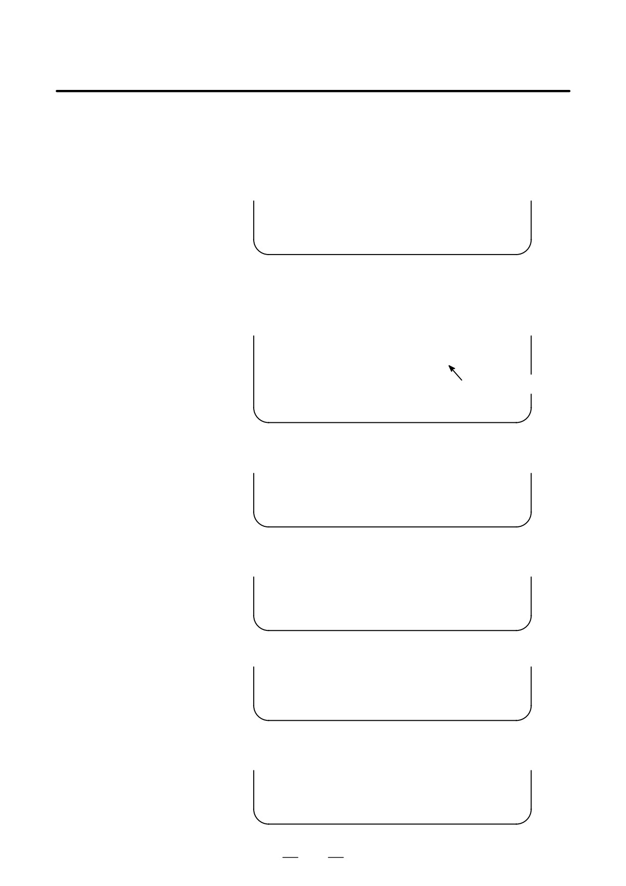
1
Select “1. SRAM BACKUP.” The following confirmation message is
displayed. The backup file name may be displayed according to the
SRAM capacity.
2
Press [YES] to start backup.
*** MESSAGE ***
BACKUP SRAM DATA OK ? HIT YES OR NO.
3
If a backup file is already on the memory card, you will be prompted
to confirm whether to permit overwriting.
4
The name of the file being written to the memory card is displayed in
the FILE NAME: field.
SRAM SIZE
: 0.5MB (BASIC)
FILE NAME
: SRAM0_5A.FDB
³ MEMORY CARD
Name of the file being
*** MESSAGE ***
saved
SRAM DATA WRITING TO MEMORY CARD.
5
Upon terminating normally, the system displays the following
message. Press the [SELECT] soft key.
*** MESSAGE ***
SRAM BACKUP COMPLETE. HIT SELECT KEY.
[Restoring the data]
1
Select “2. RESTORE SRAM.” The system displays the following
message. Press the [YES] key.
*** MESSAGE ***
RESTORE SRAM DATA OK ? HIT YES OR NO.
2
The system displays the following message during restoration.
*** MESSAGE ***
RESTORE SRAM DATA FROM MEMORY CARD.
3
Upon terminating normally, the system displays the following
message. Press the [SELECT] soft key.
*** MESSAGE ***
RESTORE COMPLETE. HIT SELECT KEY.
927
C. BOOT SYSTEM
APPENDIX
B-63525EN/02
D Others
1
Name of backup file
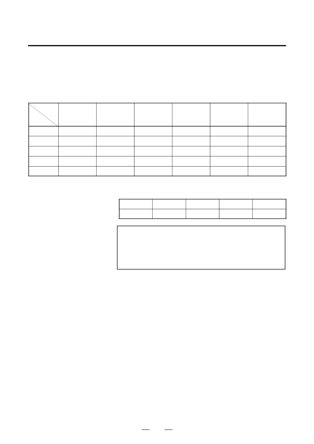
The name of the backup file written to the memory card by the SRAM
backup function depends on the size of the SRAM installed in the
CNC.
When the size of SRAM is 1MB or larger, backup files are created in
units of 512 KB.
Number
1
2
3
4
5
6
of
files
SRAM
size
256KB
SRAM256A.FDB
0.5MB
SRAM0_5A.FDB
1.0MB
SRAM1_0A.FDB
SRAM1_0B.FDB
2.0MB
SRAM2_0A.FDB
SRAM2_0B.FDB
SRAM2_0C.FDB
SRAM2_0D.FDB
3.0MB
SRAM3_0A.FDB
SRAM3_0B.FDB
SRAM3_0C.FDB
SRAM3_0D.FDB
SRAM3_0E.FDB
SRAM3_0F.FDB
The backup file for SRAM on the PMC-RE, CAPII, or LCB board
will have the following extension:
Board
MAIN
PMC-RE
CAPII
LCB
Extension
FDB
PMC
CAP
LCB
CAUTION
If data such as parameters was restored from a memory
card to SRAM in a system using an absolute pulse coder,
set bit 4 (APZ) of parameter No. 1815 to 0, and set the
reference point again.
928
B-63525EN/02
APPENDIX
C. BOOT SYSTEM
C.2.6
MEMORY CARD FILE
DELETE Screen
D Description
This screen is used to delete a file from a memory card.
D Screen configuration
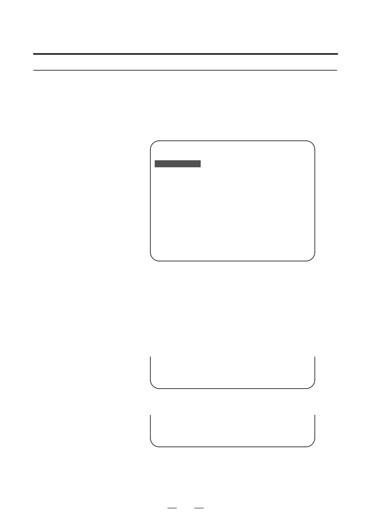
(1)
SRAM DATA LOADING
1/1
FILE DIRECTORY
(2)
B1H1A_B1.MEM
B1H1A_A1.MEM
(3)
END
*** MESSAGE ***
(4)
SELECT FILE AND HIT SELECT KEY.
[ SELECT ][ YES
][ NO
][ UP
][ DOWN
]
(1) : Screen title. Tlhe current page number (n) and the total number
of pages (m) are displayed, in n/m format, at the right end.
(2) : Files on the memory card
(3) : Option for returning to the previous menu
(4) : Message
D Operating procedure
1
Press the [SELECT] key to select the name of the file to be deleted
from the memory card.
2
The system displays the following confirmation message. Press the
[YES] key.
*** MESSAGE ***
DELETE OK ? HIT YES OR NO.
3
When a file has been deleted normally, display the following message.
Press the [SELECT] key.
*** MESSAGE ***
DELETE COMPLETE. HIT SELECT KEY.
929

C. BOOT SYSTEM
APPENDIX
B-63525EN/02
C.2.7
MEMORY CARD
FORMAT Function
D Description
This function is used to format a memory card. Memory cards must be
formatted before they can be used for the first time or before they can be
re-used after their data has been destroyed or lost because of, for example,
battery failure.
D Operating procedure
1
From the SYSTEM MONITOR MAIN MENU screen, select “7.
MEMORY CARD FORMAT.”
2
The system displays the following confirmation message.
Press the [YES] key.
*** MESSAGE ***
MEMORY CARD FORMAT OK ? HIT YES OR NO.
3
The system displays the following message during formatting :
*** MESSAGE ***
FORMATTING MEMORY CARD.
4
When a card has been formatted normally, the system display the
⋅
following message.
⋅
Press the [SELECT] key.
*** MESSAGE ***
FORMAT COMPLETE. HIT SELECT KEY.
930
B-63525EN/02
APPENDIX
C. BOOT SYSTEM
C.2.8
LOAD BASIC SYSTEM
Function
D Description
The function is used to terminate the boot system and activate the CNC.
D Operating procedure
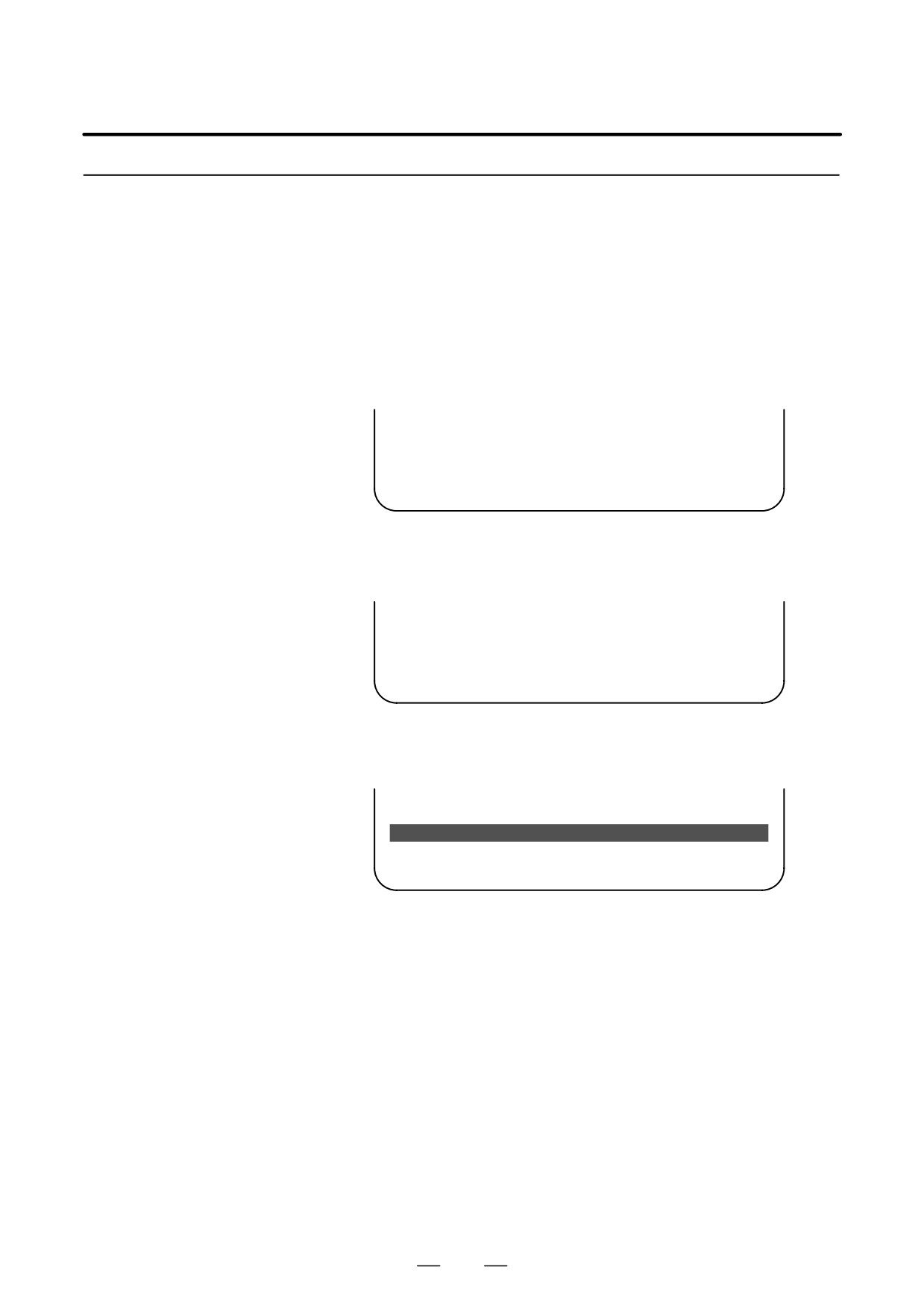
From the MAIN MENU screen, select “9. END.” The system displays
the “ARE YOU SURE? HIT YES OR NO” message. To terminate the
boot system and activate the CNC, press the [YES] soft key. Press the
[NO] soft key, and you will be brought back to the main menu.
*** MESSAGE ***
ARE YOU SURE ? HIT YES OR NO.
[ SELECT ][ YES
][ NO
][ UP
][ DOWN
]
1
After pressing the [YES] soft key
The system checks the NC BASIC system file in the flash ROM. The
system displays the following message :
*** MESSAGE ***
CHECK CNC BASIC SYSTEM.
[ SELECT ][ YES
][ NO
][ UP
][ DOWN
]
When the NC BASIC system file is found to be normal, the system
sends the system file to DRAM and starts the NC basic system. During
loading, the system blinks the following message.
*** MESSAGE ***
LOADING BASIC TO DRAM
[ SELECT ][ YES
][ NO
][ UP
][ DOWN
]
If the contents of the NC BASIC SYSTEM file are found to have been
damaged or destroyed, the system returns to the processing selection
state, in exactly the same way as when the [NO] soft key is pressed.
931