FANUC Series 16i/160i/160is-MODEL B, Series 18i/180i/180is-MODEL B, Series 21i/210i/210is-MODEL B. MAINTENANCE MANAUL - page 33
C. BOOT SYSTEM
APPENDIX
B-63525EN/02
2
If the [NO] soft key is pressed, the system returns to the processing
selection state as shown below :
SYSTEM MONITOR MAIN MENU
60M5-01
1. SYSTEM DATA LOADING
2. SYSTEM DATA CHECK
3. SYSTEM DATA DELETE
4. SYSTEM DATA SAVE
5. SRAM DATA BACKUP
6. MEMORY CARD FILE DELETE
7. MEMORY CARD FORMAT
10. END
*** MESSAGE ***
SELECT MENU AND HIT SELECT KEY.
[ SELECT ][ YES
][ NO
][ UP
][ DOWN
]
932
B-63525EN/02
APPENDIX
C. BOOT SYSTEM
The following table lists and explains error messages in alphabetical
C.3
order.
ERROR MESSAGES
AND REQUIRED
ACTIONS
Message
Description and required action
B
BOOT ROM PARITY.
The contents of flash memory containing boot software was de-
PLEASE POWER OFF.
stroyed. Replace the CPU card.
C
CHANGE MEMORY CARD.
The memory card becomes full in the middle of SRAM backup op-
AND HIT YES OR NO.
eration. Replace the card with a memory card containing enough
free space.
D
DELETE ERROR.
An attempt to delete a file from flash ROM was unsuccessful. Retry the
HIT SELECT KEY.
deletion. If the second attempt also fails, the flash ROM may have
been damaged or destroyed. Replace the flash ROM module.
DEVICE ERROR (CNC x)
An attempt to write data to flash ROM was unsuccessful. Retry the
write operation. If the second attempt also fails, the flash ROM may
have been damaged or destroyed. Repalce the flash ROM module.
F
FILE SAVE ERROR.
An attempt to write a file to a memory card was unsuccessful. Check
HIT SELECT KEY.
that the memory card is not damaged.
Note) Check that the memory card’s battery is not exhusted, that its
circuitry has not been damaged, and that it is securely inserted
into its slot.
FLASH MEMORY NO SPACE
There is insufficient free flash ROM to store the selected file. Delete
any unnecessary files from flash ROM.
FLASH ROM MODULE NOT EXIST.
The flash ROM module is not mounted on that CNC system. Put the
HIT SELECT.
flash ROM module on the board.
G
GRAPHIC SOFT IS NOT FOUND.
Graphic software is required. Load appropriate graphic software for
BOOT STOP.
the hardware in flash ROM.
I
ILLEGAL FORMAT FILE
The selected file cannot be read into flash memory. The selected file
or the header information for flash ROM may have been damaged or
destroyed.
ILLEGAL FROM MODULE.
The flash ROM module ID is illegal. Check the drawing No. of the flash
HIT SELECT KEY.
ROM module.
ILLEGAL SRAM MODULE.
The SRAM module ID is illegal. Check the drawing No. of the SRAM
HIT SELECT KEY.
module.
L
LOADING ERROR.
An error occurred while loading data into flash ROM.
HIT SELECT KEY.
Do not touch the memory card while loading data.
933
C. BOOT SYSTEM
APPENDIX
B-63525EN/02
Message
Description and required action
M
MAX EXTENSION OVER.
The extension number added to a file name exceeds 031. Delete any
HIT SELECT KEY.
unnecessary backup files from the memory card.
MEMORY CARD BATTERY ALARM.
The memory card’s battery is exhausted. Replace the battery.
HIT SELECT.
MEMORY CARD FULL.
The memory card is full. Delete any unnecessary files from the
HIT SELECT KEY.
memory card. Alternatively, replace the memory card with another
card having sufficient free space.
MEMORY CARD IS NOT
The use of this memory card is not supported. Use only FANUC-
AVAILABLE. HIT SEL.
recommended memory cards, as described in the order list.
MEMORY CARD MOUNT ERROR.
The memory card could not be accessed. Check that the memory card
HIT SELECT KEY
is normal.
MEMORY CARD NOT EXIST.
The memory card is not inserted into its slot. Check that the memory
HIT SELECT KEY.
card is pushed fully home.
MEMORY CARD PROTECTED.HIT
Although writing to the memory card was selected, the write inhibit
SELECT KEY.
switch is set. Disable the write inhibit switch.
Note) Check that the memory card’s battery is not exhusted, that its
circuitry has not been damaged, and that it is securely inserted
into its slot.
MEMORY CARD TYPE IS NOT
Write has been attempted to an incompatible flash memory card. Use
AVAILABLE.
only the flash ROM cards recommended by FANUC. Recommended
flash ROM cards are listed in the ordering list.
MEMORY CARD RESET ERROR.
Access to a memory card failed. The memory card’s battery may have
HIT SELECT KEY.
gone dead, the memory card may have been damaged electrically, or
the memory card may not be inserted in the slot securely.
MEMORY CARD WRITE ERROR.
Access to the memory card has failed. Check whether the memory
HIT SELECT KEY.
card is defective.
Note) Check that the memory card’s battery is not exhusted, that its
circuitry has not been damaged, and that it is securely inserted
into its slot.
N
NMI OCCURRED.
A hardware or software error occurred. Determine the procedure
PLEASE POWER OFF.
which causes the error, and report it to FANUC together with the series
and edition of the boot software.
P
PLEASE FORMAT FLASH TYPE
It is not possible to delete only specific files from a flash ROM card, due
CARD.HIT SEL.
to the characteristics of the memory used. To delete a file it is neces-
sary to delete all files on the card, by using the FORMAT function.
R
ROM PARITY ERROR:
The NC BASIC is parity error. Check whether NC BASIC is in flash
NC BASIC. HIT SELECT.
ROM, using SYSTEM DATA CHECK.
S
SRAM DATA BACKUP ERROR.
An attempt to write a backup file to a memory card failed.
HIT SELECT KEY.
Check that the memory card is normal.
Note) Check that the memory card’s battery is not exhusted, that its
circuitry has not been damaged, and that it is securely inserted
into its slot.
SRAM PARITY OCCURRED.
A parity error was detected during backup operation of SRAM (Cau-
PLEASE POWER OFF.
tion).
934

B-63525EN/02
APPENDIX
C. BOOT SYSTEM
CAUTION
1
Action to be taken when an SRAM parity error is detected during backup of SRAM in the boot
system
The SRAM area of each CNC shipped from the factory is cleared and is free of parity errors.
However, shock applied to the CNC during transportation may cause a parity error in the SRAM
area. A parity error may also occur in the SRAM area when the CNC was kept switched off for
one year or longer, and the battery has been exhausted. If a parity error occurs in the SRAM
area, the data held in the SRAM area is not guaranteed. However, the CNC does not always
use the entire SRAM area. A parity error is not detected by hardware unless the part containing
the error is read. Therefore, if a parity error occurs in an area not accessed by the CNC, the
CNC may operate normally. The SRAM backup function of the boot system reads the entire
SRAM area. So, a parity error may occur in the middle of backup operation even when the CNC
has operated normally. In this case, the SRAM data of the CNC is not guaranteed, and the data
cannot be backed up using the SRAM backup function of the boot system. Nevertheless, the
CNC may operate normally. So, it is recommended that necessary data be backed up using
the Floppy Cassette or Handy File, data all clear operation be performed, then the backed up
data be restored in the CNC. Once all clear operation is performed, the parity error can be
removed. Then, the SRAM backup function of the boot system can be used.
935
D. MEMORY CARD SLOT
APPENDIX
B-63525EN/02
MEMRY CARD SLOT
D
D.1 OVERVIEW
937
D.2 MEMORY CARD TYPES (FUNCTIONS)
938
D.3 HARDWARE CONFIGURATION
939
936
B-63525EN/02
APPENDIX
D. MEMORY CARD SLOT
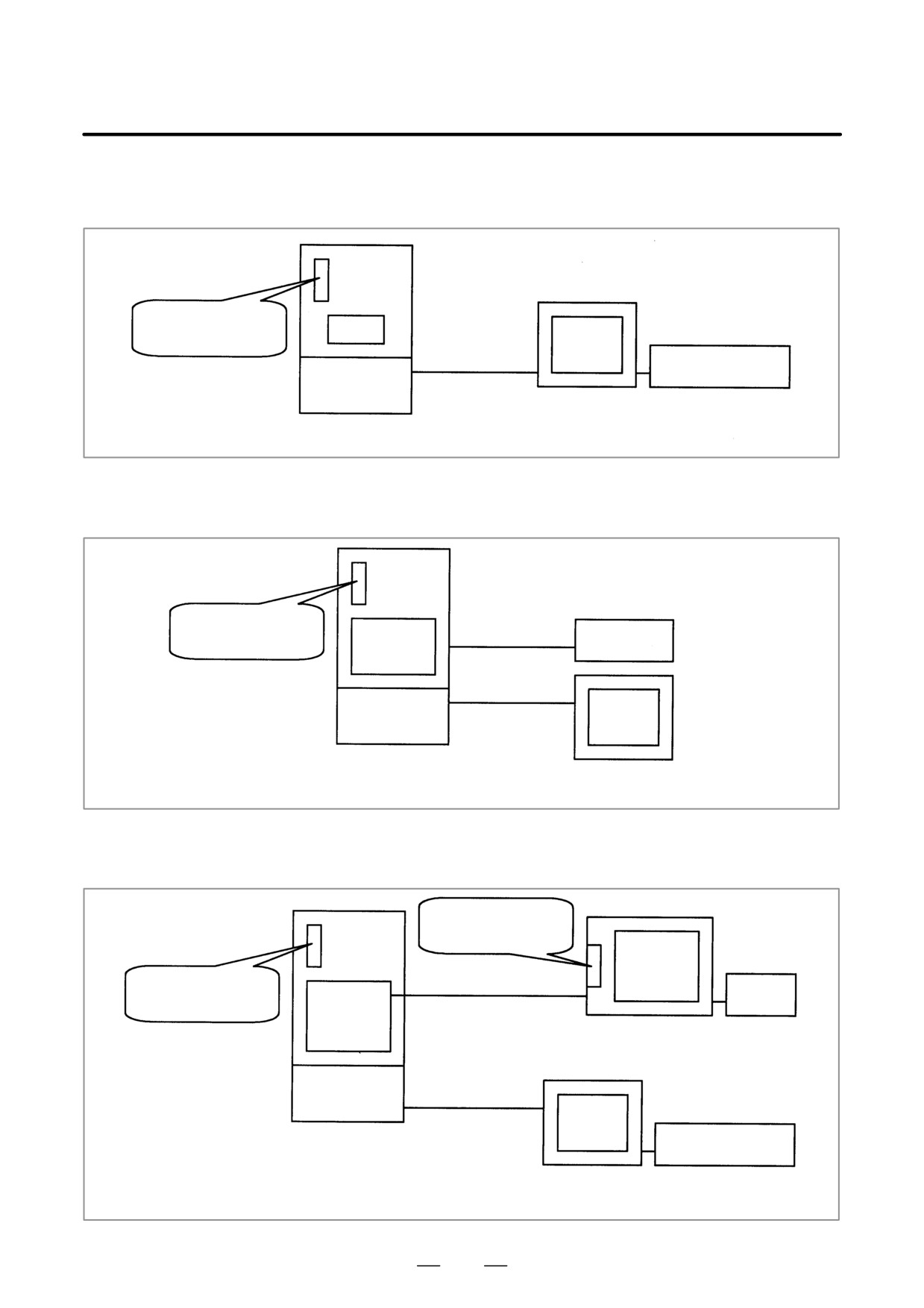
Whether a memory card slot is provided or not depends on the hardware
D.1
configuration. See the following table:
OVERVIEW
Hardware
Card slot on LCD unit
Card slot on control unit
configuration
Type 1
Provided
No card slot
Type 2
Provided
Provided
Type 6
(This slot, however, cannot be
used.)
Type 3
No card slot
Provided
Type 4
No card slot
Provided
Type 5
(See NOTE given below.)
(Supplementary)
- Types 1 to 6 indicate hardware configuration. See Section D.3.
- When both the LCD unit and control unit have a memory card slot,
only the memory card slot on the LCD unit can be used.
NOTE
When the hardware configuration is type 4 or type 5,
software write operation and other operations are
implemented by open CNC functions.
937

D. MEMORY CARD SLOT
APPENDIX
B-63525EN/02
SRAM memory card
D.2
FROM memory card
Data I/O
MEMORY CARD
Flash ATA card
TYPES (FUNCTIONS)
Modem card (for remote diagnosis)
NOTE
For details of the types of usable memory cards, see the
ordering list.
938
B-63525EN/02
APPENDIX
D. MEMORY CARD SLOT
D.3
HARDWARE
CONFIGURATION
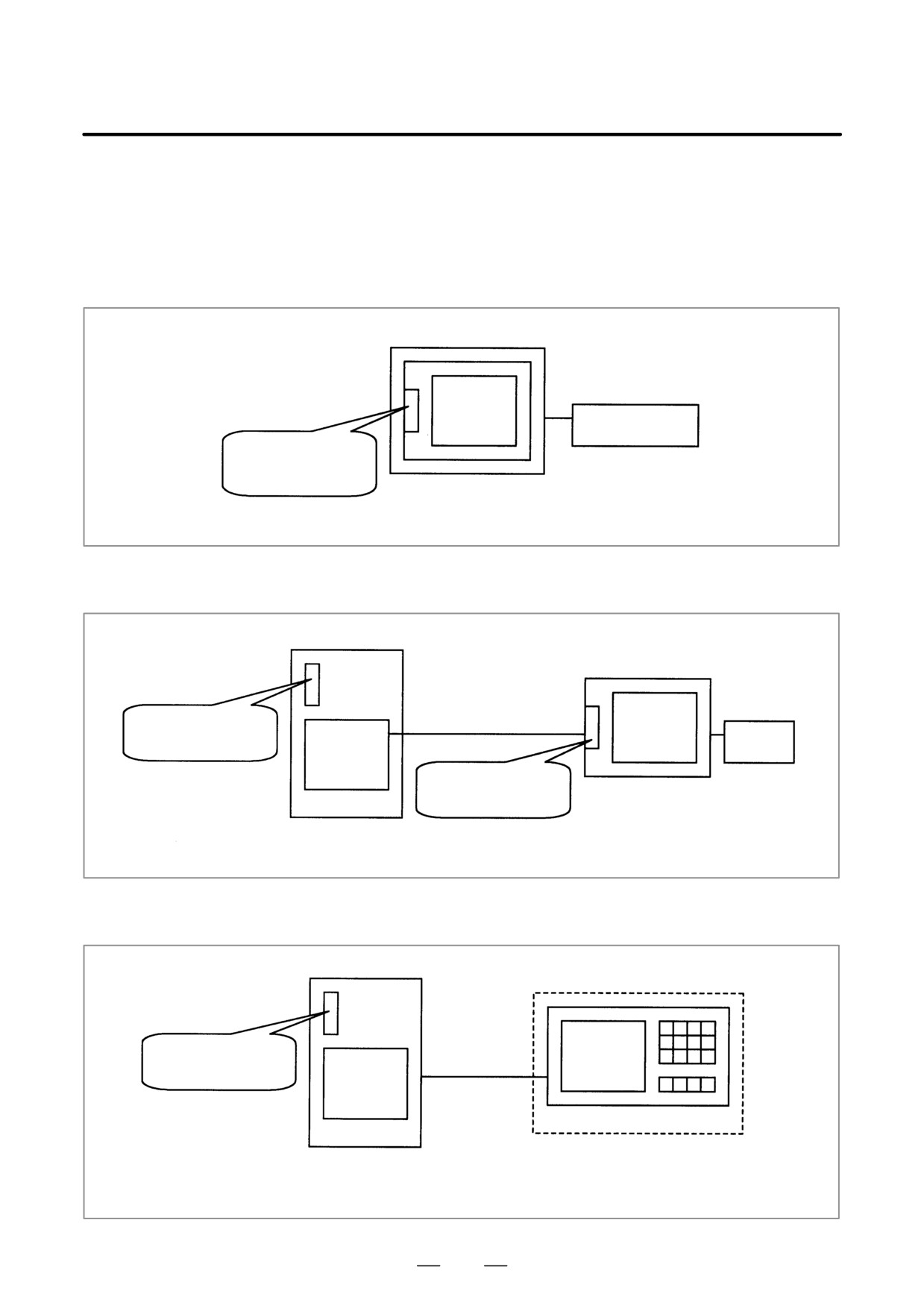
D Type 1
LCD-mounted type
LCD
MDI
Card slot on
LCD unit
Control unit (LCD-mounted type)
D Type 2
Stand-alone type (with an LCD unit)
Optical cable
Card slot on
LCD
LCD
control unit
MDI
link
card
Card slot on
LCD unit
LCD unit for stand-
alone type
Control unit
D Type 3
Stand-alone type (with a CRT/MDI unit)
Card slot on
CRT
Electrical wire
control unit
CRT
link
card
CRT/MDI unit
(The CRT/MDI unit for the Power
Control unit
Mate i series is usable.)
939
D. MEMORY CARD SLOT
APPENDIX
B-63525EN/02
D Type 4
Stand-alone type (with CNC display unit with PC functions or an PANEL
i and FA keyboard or PC)
Card slot on
control unit
PC
Optical cable
FA keyboard
HSSB
board
CNC display unit with PC
functions, PANEL i, or
Control unit
personal computer
D Type 5
Stand-alone type (with CNC display unit with PC functions or an PANEL
i and FA keyboard or PC)
Card slot on
MDI
Electric wire
Standard
control unit
card
MDI
Optical cable
HSSB
PC
board
Control unit
CNC display unit with PC functions,
PANEL i, or personal computer
D Type 6
Stand-alone type (with an LCD unit and MDI, CNC display unit with PC
functions or an PANEL i and FA keyboard or PC)
Card slot on
LCD unit
LCD
Optical cable
Card slot on
MDI
control unit
LCD
link
card
LCD unit for stand-
alone type
HSSB
Optical cable
board
PC
Control unit
FA keyboard
CNC display unit with PC functions,
PANEL i, or personal computer
940
E. LED DISPLAY AND MAINTENANCE
B-63525EN/02
APPENDIX
OF STAND-ALONE TYPE UNIT
LED DISPLAY AND MAINTENANCE OF STAND-ALONE
TYPE UNIT
E
E.1
OVERVIEW
942
E.2
LAYOUT OF THE 7-SEGMENT LED AND
SWITCHES
943
E.3
OPERATION
944
941
E. LED DISPLAY AND MAINTENANCE
OF STAND-ALONE TYPE UNIT
APPENDIX
B-63525EN/02
FANUC Series
16i/18i/21i
(referred to as FS16i hereinafter) of
E.1
stand-alone type is equipped with a 7-segment LED, rotary switch, and
OVERVIEW
push switch.
When no MDI is included in the system configuration or when the MDI
becomes defective and cannot be used, battery backed-up data can be
saved and restored by using the rotary switch and push switch.
When the MDI can be used, use these switches for maintenance of the
boot function.
942
E. LED DISPLAY AND MAINTENANCE
B-63525EN/02
APPENDIX
OF STAND-ALONE TYPE UNIT
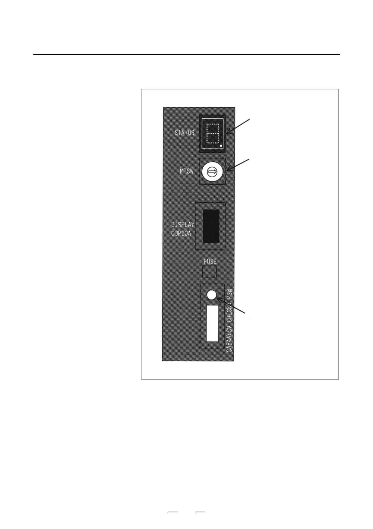
The 7-segment LED, rotary switch, and push switch are located as shown
E.2
below.
LAYOUT OF THE
7-SEGMENT LED
AND SWITCHES
7-segment LED (STATUS)
Rotary switch (MTSW)
Push switch (PSW)
943
E. LED DISPLAY AND MAINTENANCE
OF STAND-ALONE TYPE UNIT
APPENDIX
B-63525EN/02
E.3
OPERATION
E.3.1
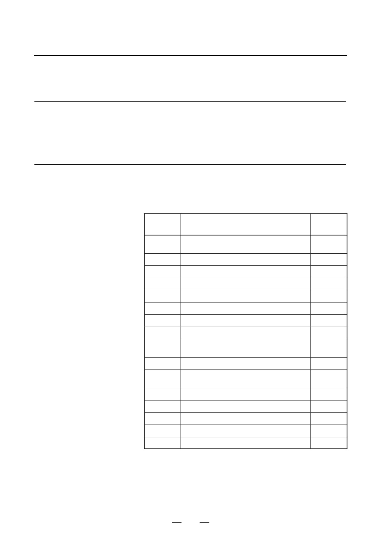
Before turning on the power, select a function number by using the rotary
switch. When the power is turned on after the selection with the rotary
Operation Before
switch, the number corresponding to the selected function number is
Power-On
indicated on the LED. The indication blinks at intervals of about one
second.
Each function is assigned a number. This number is called a function
E.3.2
number hereinafter in this manual. The function numbers that can be
Function Number
selected with the rotary switch are listed below. Do not set the reserved
function numbers.
(If a reserved function number is set, the system
operates as if function number 0 were selected.)
Function
Explanation
Remarks
number
0
Normal state. After terminating maintenance operation,
always set this number.
1
Reserved
2
Sets a device number for the display link function.
3
Reserved
4
Maintenance switch
5
Memory all clear
6
Reserved
7
Reserved
8
Saves battery backed-up main board data in a memory
card at a time.
9
Reserved
A
Restores battery backed-up main board data from a
memory card at a time.
B
Reserved
C
Reserved
D
Reserved
E
Reserved
F
Reserved
944
E. LED DISPLAY AND MAINTENANCE
B-63525EN/02
APPENDIX
OF STAND-ALONE TYPE UNIT
E.3.3
Seven-Segment LED
Display
E.3.3.1
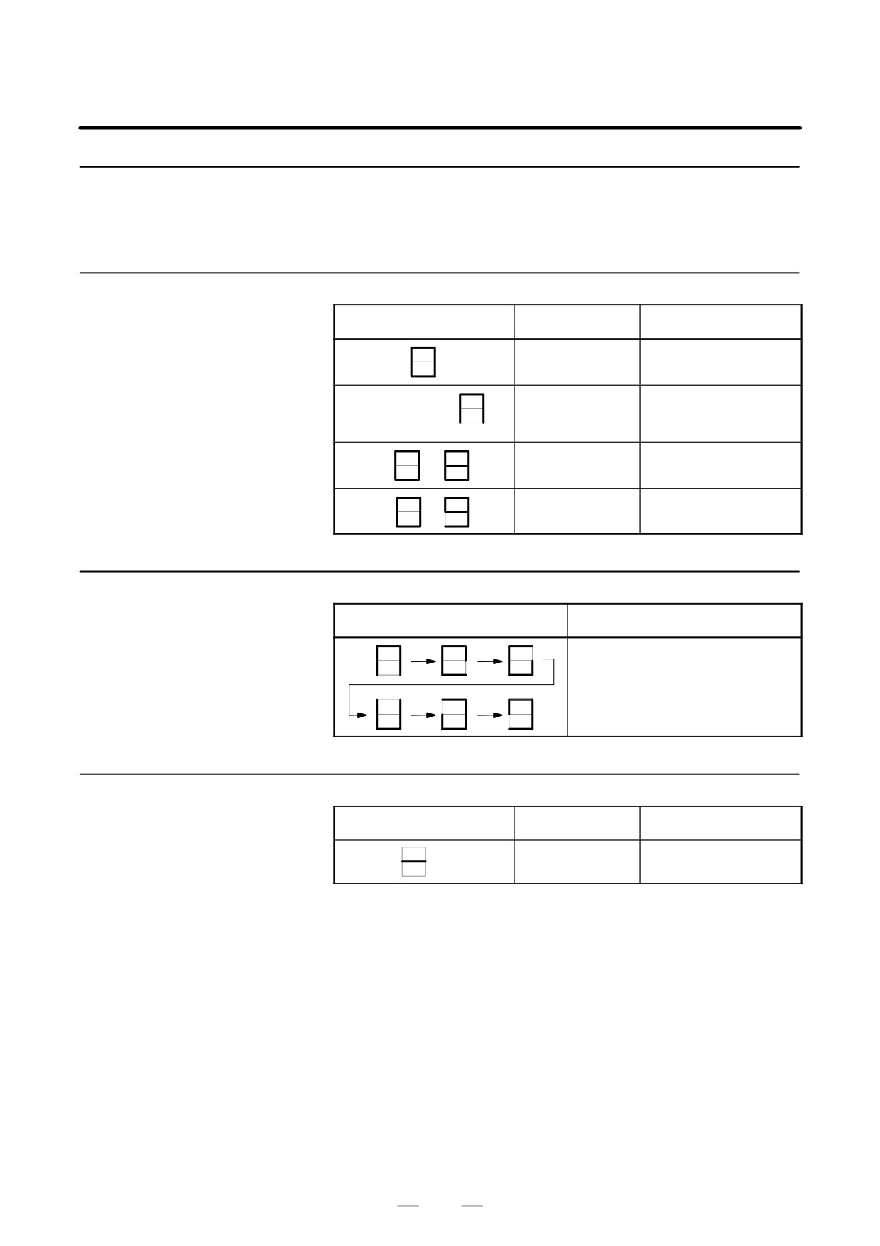
NC status display
Number displayed on LED
Blink/not blink
Description
Not blink
Automatic operation is
paused, stopped, or reset.
(Rotation of character
)
Not blink
Automatic operation start
signal
When STL <F000#5> = 1
Blink
System alarm status
Number (
to
)
Number (
to
)
Not blink
Status change at power-on
E.3.3.2
LED display during
LED indication
Description
automatic operation
Automatic operation start signal
When STL <F000#5> = 1
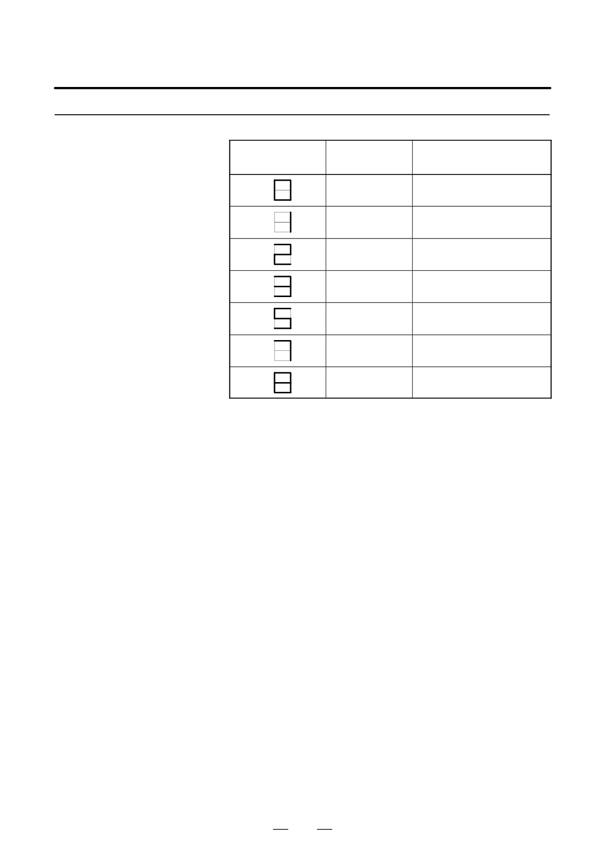
E.3.3.3
LED display when the
Number displayed on LED
Blink/not blink
Description
push switch is pressed
Not blink
The push switch has been
pressed normally.
945
E. LED DISPLAY AND MAINTENANCE
OF STAND-ALONE TYPE UNIT
APPENDIX
B-63525EN/02
E.3.3.4
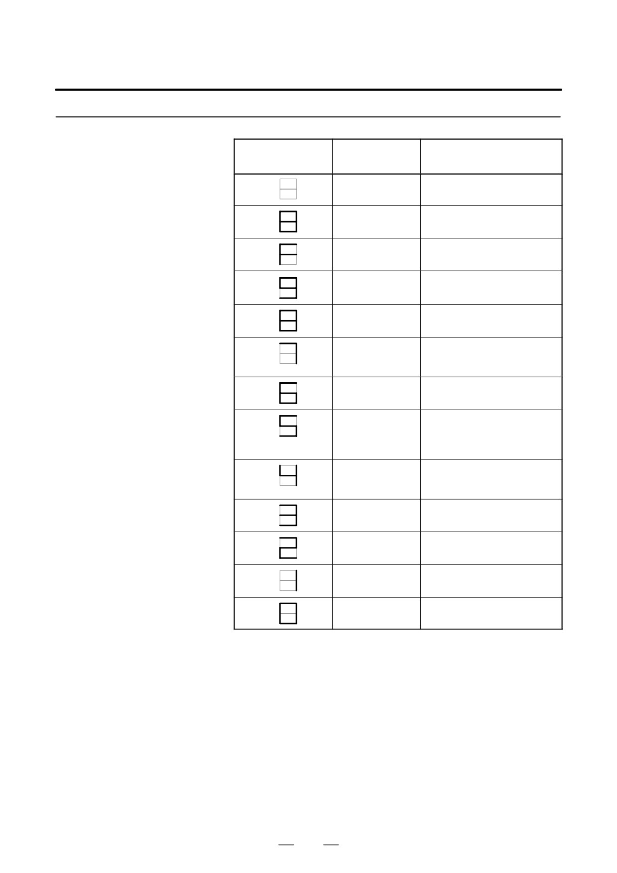
When a system alarm is issued, a number blinks on the 7-segment LED.
LED display when a
Number on LED
System alarm
Type of system alarm
system alarm is issued
(blinking)
number
In the 900’s
ROM PARITY
In the 910’s
SRAM PARITY,
DRAM PARITY
In the 920’s
SERVO ALARM
In the 930’s
CPU INTERRUPT,
SRAM ECC ERROR
In the 950’s
PMC SYSTEM ALARM
In the 970’s
NON MASK INTERRUPT,
BUS ERROR
Others
Other system alarms
946
E. LED DISPLAY AND MAINTENANCE
B-63525EN/02
APPENDIX
OF STAND-ALONE TYPE UNIT
E.3.3.5
Display on the
Number displayed
On/off status of
Meaning
on LED
4 LEDs
7-segment LED at
power-on
jjjj
Power is not on.
JJJJ
Power is turned on, but the CPU
does not yet start.
JJJJ
NC system loading is started by the
boot system.
jJJJ
The NC system has started, and
RAM initialization has terminated.
JjJJ
Wait for ID setting for each board
jjJJ
ID setting for each board has termi-
nated, and CRT initialization has ter-
minated.
JJjJ
FANUC bus initialization has termi-
nated.
jJjJ
Loading from F-ROM has termi-
nated, PMC initialization has termi-
nated, and the series/edition screen
is displayed.
JjjJ
Hardware configurationinformation
setting for each module has com-
pleted.
jjjJ
PMC ladder initialization has com-
pleted.
jJJj
Wait for digital servo and spindle ini-
tialization
JJJj
Digital servo and spindle initialization
has completed.
Jjjj
Initialization has completed. In nor-
mal operation state.
j : Off J : On
947
E. LED DISPLAY AND MAINTENANCE
OF STAND-ALONE TYPE UNIT
APPENDIX
B-63525EN/02
E.3.4
Operation of Each
Function
D Function number 2
This function sets a device number for the display link function.
(1) Check that number 2 blinks on the LED, and press the push switch.
(2) Number 2 is displayed on the LED. Press the push switch.
(3) Sixteen numbers from 0 to F are displayed on the LED one by one at
intervals of about one second. When the device number you want to
set appears on the LED, press the push switch.
(4) The selected device number blinks on the LED. Press the push switch.
(5) The device number used for the display link function is displayed on
the LED.
D Function number 4
This function allows the maintenance switches to be used to display data
without using any display unit.
(1) Check that number 4 blinks on the LED. Press the push switch.
(2) Number 4 is displayed on the LED. Press the push switch.
(3) Number 0 is displayed on the LED. Press the push switch.
(4) Numbers 0 and 2 are displayed alternately on the LED at intervals of
about one second. When 2 is displayed, press the push switch.
(5) The device number used for the display link function is displayed on
the LED.
D Function number 5
This function clears all the battery backed-up SRAM data. The device
number for the display link function is also cleared. Once the device
number has been cleared, the device number is set to 0.
(1) Check that number 5 blinks on the LED. Press the push switch.
(2) Number 5 is displayed on the LED. Press the push switch.
(3) The display on the LED changes from - to F to 9 to 8 to 7 to 6 to 5 to
4 to 3 to 2 to 1 to 0 in this order.
(4) After all-clear operation terminates normally, the LED display stops
changing at number 0.
(5) Turn off the power, set the rotary switch to 0 (normal state), then turn
on the power again.
948
E. LED DISPLAY AND MAINTENANCE
B-63525EN/02
APPENDIX
OF STAND-ALONE TYPE UNIT
D Function number 8
This function saves battery backed-up main board data in a memory card
at a time. The data saved using this function can be restored at a time by
performing the operation for function number A or by using the
SRAMDATABACKUP function of the boot function.
(1) In the memory card slot (MEMORY CARD CNM1B) of the control
unit, insert a formatted memory card having at least 512 KB of
available space.
(2) Check that number 8 blinks on the LED, and press the push switch.
(3) While data is being saved in the memory card, the LED indication
turns clockwise.
(4) If the data cannot fit in one memory card, number 3 blinks. Replace
the memory card with another one, and press the push switch.
(5) If the protect switch of the memory card is not released or if the battery
capacity of the memory card is insufficient, number 2 blinks on the
LED. Replace the memory card with another one, and press the push
switch.
(6) When the data has been saved normally, number 0 is displayed on the
LED. If the data cannot be saved normally, number 1 is displayed on
the LED.
(7) If SRAM PARITY occurs during data save operation, number 1 blinks
on the LED. In this case, it is impossible to save the data at a time.
Back up individual data items one by one, then perform all-clear
operation.
D Function number A
This function restores battery backed-up main board data from a memory
card at a time.
(1) Insert the memory card in the memory card slot (MEMORY CARD
CNM1B) of the control unit.
(2) Check that A blinks on the LED, and press the push switch.
(3) While data is being restored from the memory card, the LED
indication turns counterclockwise.
(4) If the entire data cannot be restored from the single memory card,
number 3 blinks. Replace the memory card with the next memory
card, and press the push switch.
(5) If the memory card cannot be recognized correctly, number 2 blinks
on the LED. Check the memory card status, and press the push switch.
(6) When the data has been restored normally, number 0 is displayed on
the LED. If the data cannot be restored normally, number 1 is
displayed on the LED.
949
F. MAINTENANCE OF OPEN CNC
(BOOT-UP AND IPL)
APPENDIX
B-63525EN/02
MAINTENANCE OF OPEN CNC (BOOT-UP AND IPL)
F
F.1
OVERVIEW
951
F.2
CHANGING START SEQUENCES
952
F.3
EXPLANATION OF SCREENS
954
F.3.1
Boot Screen
954
F.3.2
IPL Screen
958
F.4
OTHER SCREENS
961
F.4.1
CNC Alarm Screen
961
F.4.2
Status Screen
962
F.4.3
Option Setting Screen
964
950
F. MAINTENANCE OF OPEN CNC
B-63525EN/02
APPENDIX
(BOOT-UP AND IPL)
When the 160i/180i/210i is used or the CNC is connected to the PC over
F.1
HSSB, Ncboot32.exe can be used for the maintenance of the CNC. When
OVERVIEW
the
160is/180is/210is is used, Ncbootis.exe can be used for the
maintenance of the CNC. Unless otherwise specified, the following
examples assume the use of Ncboot32.
Ncboot32.exe provides the following functions:
S BOOT screen (for CNC system data maintenance, SRAM backup, and
so forth)
S IPL screen (for clearing SRAM, and so forth)
S Display of the CNC power-on screen
S Display of CNC alarm screen
S Re-connection in case of the occurrence of a communication error
S Start of a registered application program
Ncboot32.exe is copied in the System folder of Windows (System32
folder in Windows NT) at driver installation. At the start of Windows,
Ncboot32.exe starts automatically, and resides in the system tray.
(Icon at the center)
Supplementary 1: Multi-connection
Ncboot32.exe supports HSSB multi-connection. The CNCs connected
by HSSB are managed as nodes. The boot, IPL, and system alarm screens
are displayed in windows that are opened independently for each node.
Supplementary 2: Termination method
Normally, Ncboot32.exe need not be terminated. However, to terminate
Ncboot32.exe, right-click the icon in the system tray, and click End in the
popup menu. When the Ncboot32.exe window is open, End cannot be
selected.
NOTE
When the CNC is connected to the PC over Ethernet, use
the standard LCD/MDI for the maintenance of the CNC.
951
F. MAINTENANCE OF OPEN CNC
(BOOT-UP AND IPL)
APPENDIX
B-63525EN/02
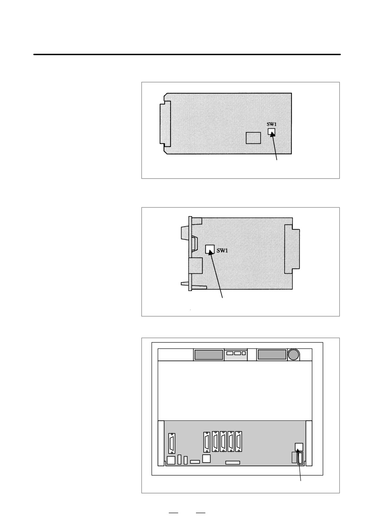
With the rotary switch on the HSSB board on the CNC side (when the
F.2
CNC does not have the PC function) or on the motherboard of the CNC
CHANGING START
(when the CNC has the PC function), the start sequence can be changed.
SEQUENCES
Position 0 can be selected as required to perform maintenance using the
boot and IPL screens.
Position 0 (maintenance)
1. Wait until communication with the CNC is established.
2. Display the boot screen.
3. Display the IPL screen.
4. Display the CNC power-on screen.
5. Initialize the work area for the data window library.
6. Start a registered application program.
7. Perform monitoring for communication errors and CNC system
alarms.
Position 1 (normal operation)
1. Wait until communication with the CNC is established.
2. Initialize the work area for the data window library.
3. Start a registered application program.
4. Perform monitoring for communication errors and CNC system
alarms.
Position 2 (asynchronous start)
1. The CNC starts without waiting for communication to be established.
2. After communication is established, the PC performs initialization
described below.
3. Initialize the work area for the data window library.
4. Start a registered application program.
5. Perform monitoring for communication errors and CNC system
alarms.
952
F. MAINTENANCE OF OPEN CNC
B-63525EN/02
APPENDIX
(BOOT-UP AND IPL)
D HSSB interface board of 16i/18i/21i of LCD-mounted type
Rotary switch
D HSSB interface board of
16i/18i/21i/160i/180i/210i/160is/180is/
210is of stand-alone type
Rotary switch
D Stand-alone type 160is/180is/210is
Rear of unit
Rotary switch
953
F. MAINTENANCE OF OPEN CNC
(BOOT-UP AND IPL)
APPENDIX
B-63525EN/02
F.3
EXPLANATION OF
NOTE
SCREENS
A mouse is required to display Ncboot32.exe screens.
F.3.1
Boot Screen
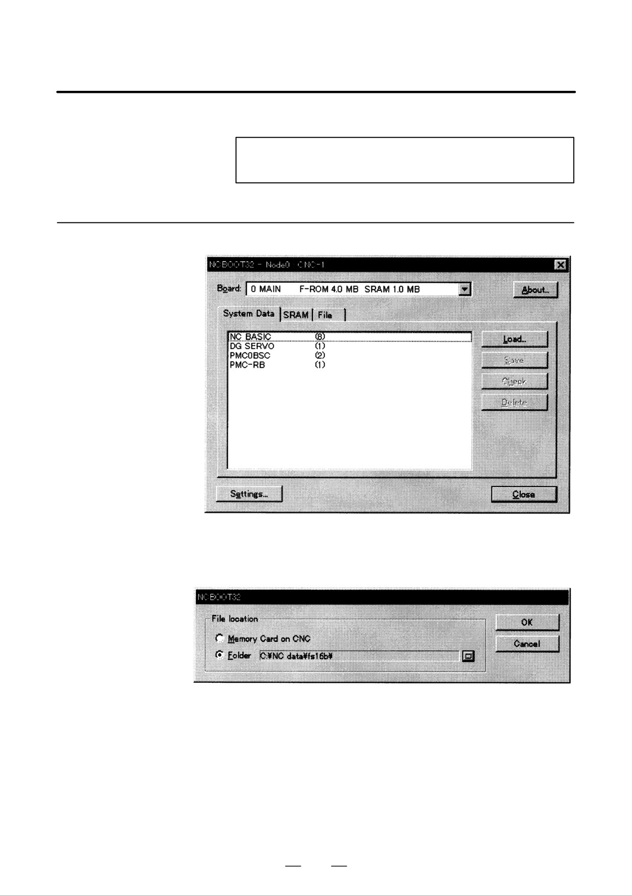
When the sub-board is provided, select a board in the [Board] list.
The area where the file is to be placed can be changed by using the
[Setting...] button.
Select the memory card on the CNC or a PC folder. The file location may
be changed at any time.
954
F. MAINTENANCE OF OPEN CNC
B-63525EN/02
APPENDIX
(BOOT-UP AND IPL)
F.3.1.1
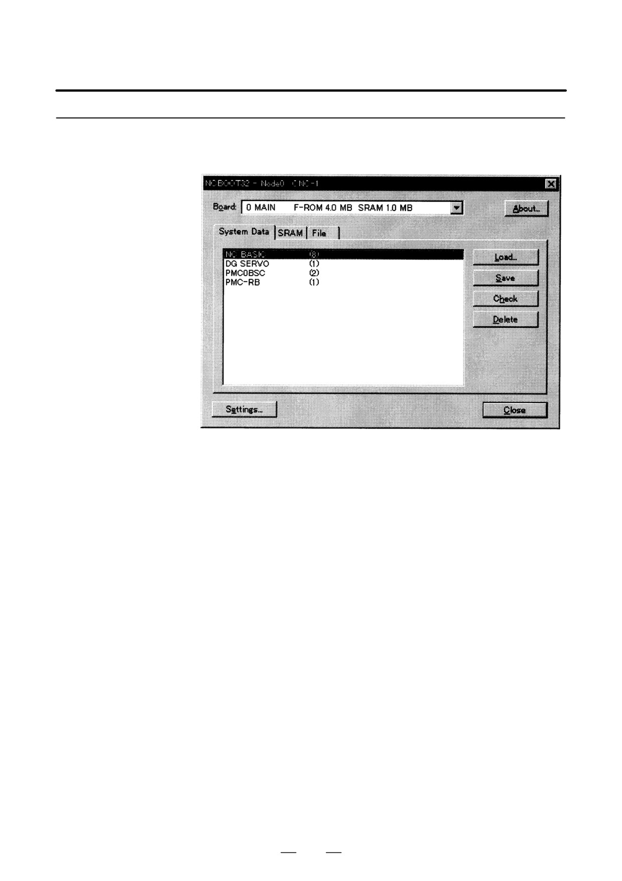
The following screen is used for manipulating system data (including
control software and ladder programs) on the NC.
System data
manipulation
[Load...] opens the file selection screen. Specify a file to be loaded.
[Save] saves the selected NC system data in a file.
[Check] checks the selected NC system data.
[Delete] deletes the selected NC system data.
955
F. MAINTENANCE OF OPEN CNC
(BOOT-UP AND IPL)
APPENDIX
B-63525EN/02
F.3.1.2
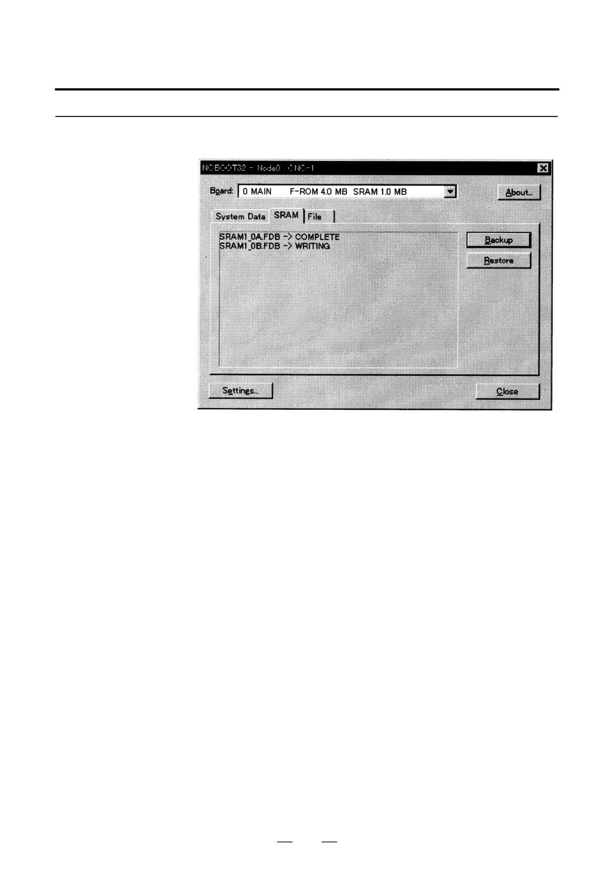
This screen is used to store and restore NC SRAM data.
SRAM operation
[Backup] stores SRAM data, and [Restore] restores SRAM data. In the
center of the screen, the progress status is displayed. As with the NC, the
backup file name is determined automatically from the SRAM size, and
cannot be renamed.
956
F. MAINTENANCE OF OPEN CNC
B-63525EN/02
APPENDIX
(BOOT-UP AND IPL)
F.3.1.3
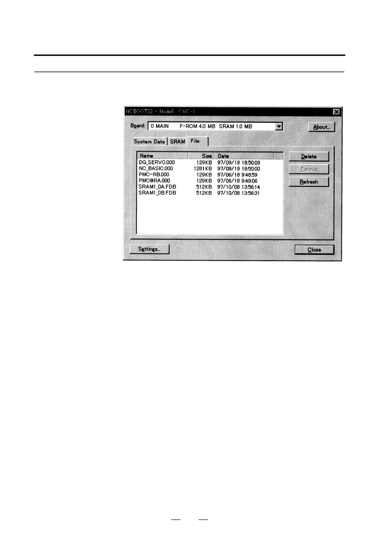
The following screen is used for operating files on a memory card in the
CNC or in a folder of the PC.
File operation
[Delete] deletes a selected file.
[Format] formats the memory card. This button is valid when the memory
card is selected by [Setting...]
[Refresh] updates the file list to the latest state. After changing memory
cards or floppy disks, click this button.
957
F. MAINTENANCE OF OPEN CNC
(BOOT-UP AND IPL)
APPENDIX
B-63525EN/02
F.3.2
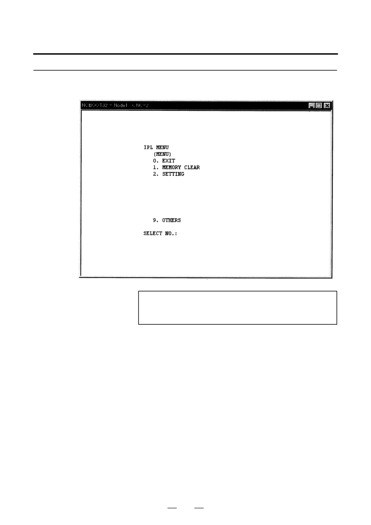
IPL Screen
NOTE
The contents of the IPL screen vary depending on the CNC
model. Follow the instructions displayed in the menu.
The CNC allows functions to be performed according to the key status set
at power-on.
The open CNC does not allow this operation. On the IPL screen, however,
equivalent functions can be executed.
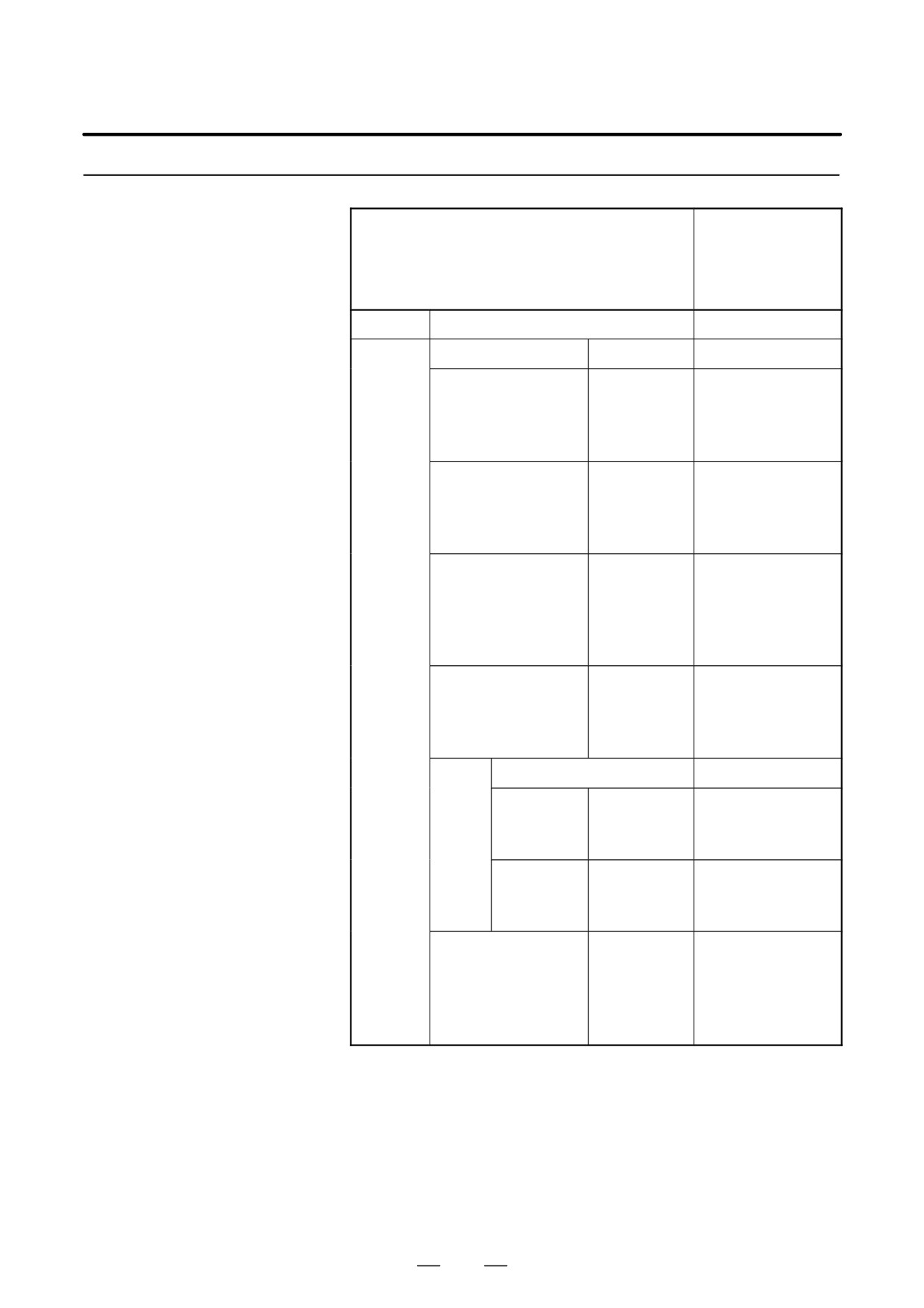
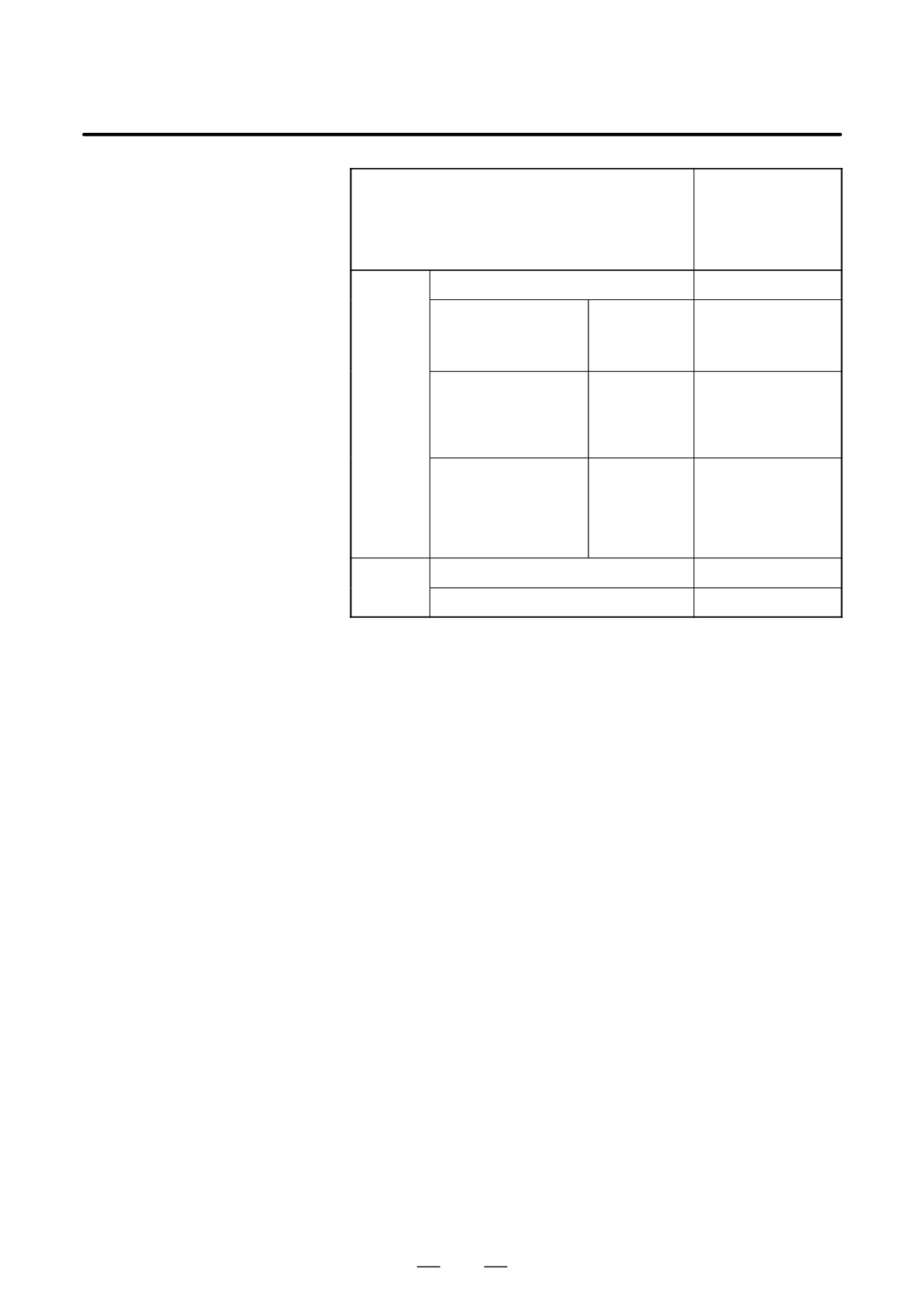
For details of the menu on the IPL screen and supported functions, see the
table given in Section F.3.2.1.
958
F. MAINTENANCE OF OPEN CNC
B-63525EN/02
APPENDIX
(BOOT-UP AND IPL)
F.3.2.1
Functions on the IPL
Corresponding MDI
key operation at
screen
Title on IPL screen
power-on
(Operation with a
standard CNC)
0. EXIT
1.
0. CANCEL
MEMORY
CLEAR
1. ALL MEMORY
0. CANCEL
1. ALL
<DELETE> + <RESET>
2. SUB
<CAM> + <2>
3. LOADER
<CAN> + <5>
2. PARAMETER AND
0. CANCEL
OFFSET
1. MAIN
<RESET>
2. SUB
<RESET> + <2>
3. LOADER
<RESET> + <5>
3. ALL PROGRAM
0. CANCEL
1. ALL
<DELETE>
2. MAIN
<DELETE> + <1>
3. SUB
<DELETE> + <2>
4. LOADER
<DELETE> + <5>
4. ADDITIONAL SRAM
0. CANCEL
1. ALL
<O> + <DELETE>
2. MAIN
<O> + <1>
3. SUB
<O> + <2>
5. PMC
0. CANCEL
1.
0. CANCEL
PARAMETER
1. CNC
<Z> + <O>
2. LOADER
<Z> + <5>
2. PROGRAM
0. CANCEL
1. CNC
<Z> + <O>
2. LOADER
<Z> + <5>
6. CAP-II
0. CANCEL
1. SUB
<SP>
MEMORY
2. CONVERSA-
<I>
TIONNAL
DATA
959
F. MAINTENANCE OF OPEN CNC
(BOOT-UP AND IPL)
APPENDIX
B-63525EN/02
Corresponding MDI
key operation at
Title on IPL screen
power-on
(Operation with a
standard CNC)
2.
0. CANCEL
SETTING
1. IGNORE OVER
0. CANCEL
TRAVEL ALARM
1. CNC
<CAN> + <P>
2. LOADER
<CAN> + <L>
2. START WITHOUT
0. CANCEL
LADDER
1. CNC SIDE
<CAN> + <Z>
2.
LOADER SIDE
< . > + <5>
3. CLANGUAGE
0. CANCEL
EXECUTOR
1. MAKE VOID
<M> + <0>
C-EXEC
2. BOOTS UP
<M> + <3>
C-EXEC APL
9.
0. CANCEL
OTHERS
1. P-CODE LOADER
<CAN> + <PROG>
960
F. MAINTENANCE OF OPEN CNC
B-63525EN/02
APPENDIX
(BOOT-UP AND IPL)
F.4
OTHER SCREENS
F.4.1
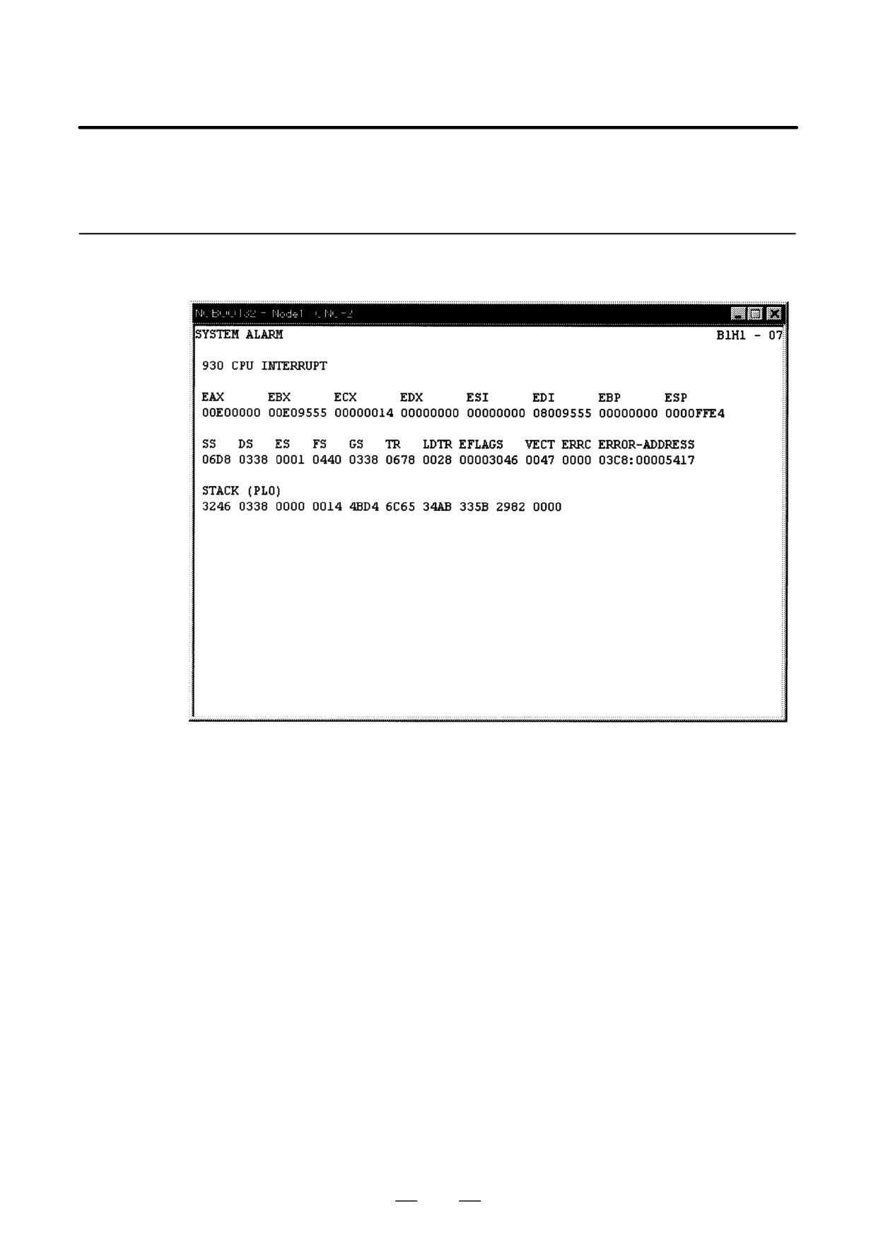
CNC Alarm Screen
This screen appears when a system alarm is issued in the CNC.
(The
above screen is an example. The displayed information varies depending
on the system alarm issued in the CNC.)
961