FANUC Series 16i/160i/160is-MODEL B, Series 18i/180i/180is-MODEL B, Series 21i/210i/210is-MODEL B. MAINTENANCE MANAUL - page 23
8. EMBEDDED ETHERNET FUNCTION
B-63525EN/02
7
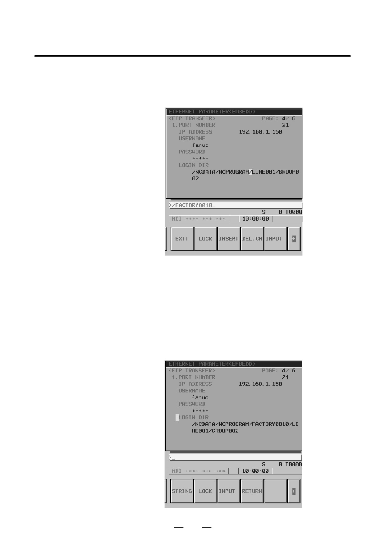
To insert
”/FACTORY0010” between
”NCPROGRAM” and
”/LINE001”, move the cursor to ”/” prefixed to ”LINE001” then type
”/FACTORY0010” with the MDI keys. Finally, press the [INSERT]
soft key.
8
To delete a character, move the cursor to the character to be deleted,
then press the [DEL.CH] soft key. This operation deletes a character
on which the cursor is placed one at a time.
9
To overwrite a character, move the cursor to the character to be
overwritten, then type a desired character with the MDI key. Finally,
press the [INPUT] soft key. This operation overwrites a character on
which the cursor is placed.
10 Upon completion of character string input, press the [RETURN] soft
key. This operation returns the cursor position and soft key display to
the state of step 1, and stores the set data in the nonvolatile memory
of the CNC.
632
B-63525EN/02
8. EMBEDDED ETHERNET FUNCTION
Method of entering special characters
The method of entering special characters such as ”\” unavailable with the
MDI keys is described below.
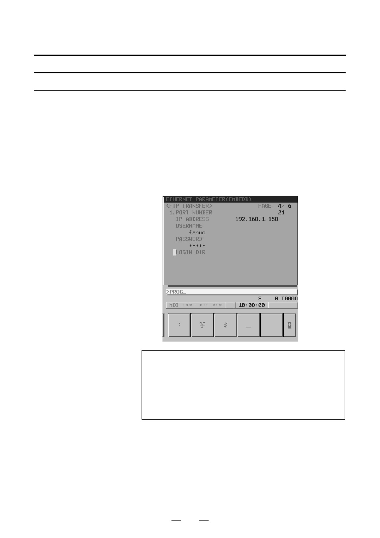
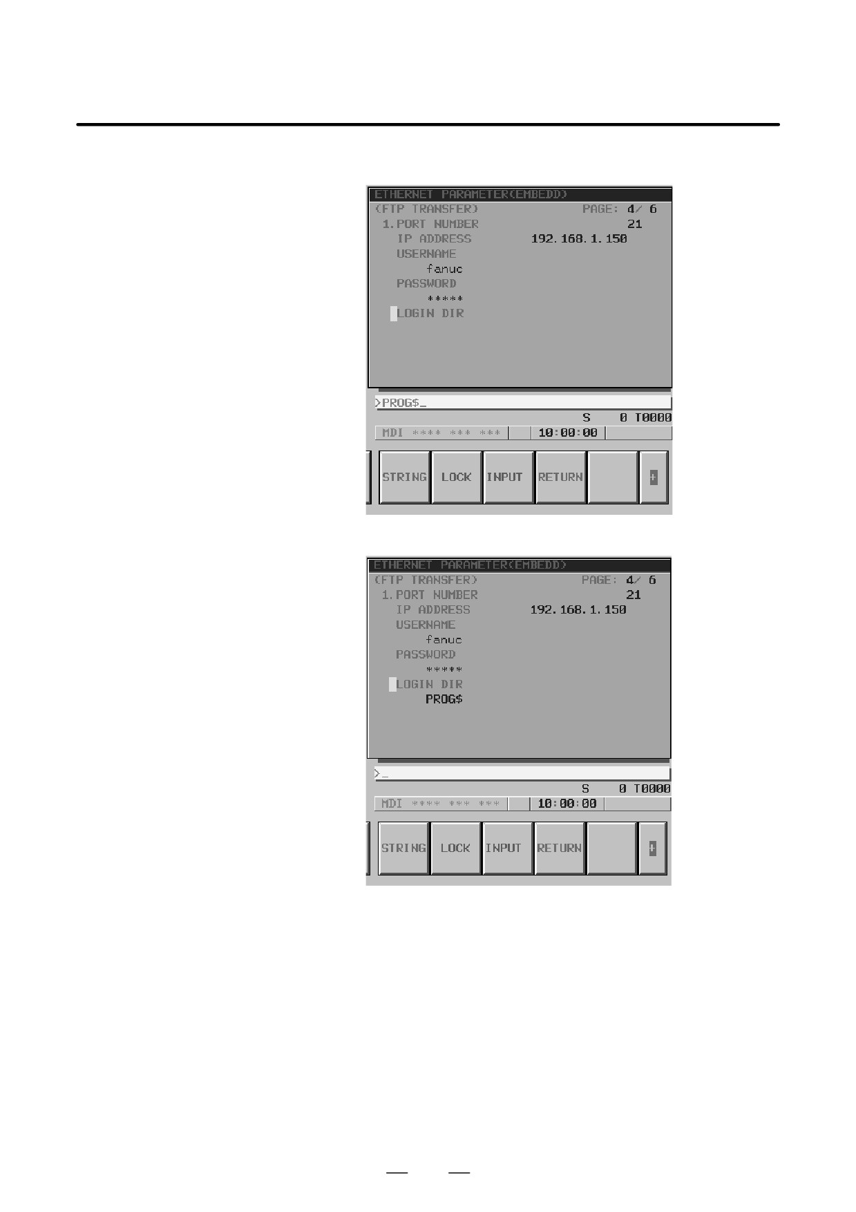
As an example, the procedure for setting the character string ”PROG$”
is described.
Procedure
1 Place the CNC in the MDI mode.
2
Display the Ethernet parameter screen.
3
Move the cursor to LOGIN DIR with cursor keys.
4
Type ”PROG” with the MDI keys, then press the continuous menu key
at the right end of the soft key display.
NOTE
Those characters unavailable with the MDI keys that are
used frequently such as :, ¥, $, and _ can be entered using
soft keys. To enter a character other than these characters,
set the ASCII code of the character in a parameter from
parameters No. 931 through No. 935.
For details, see Subsection 17.3.3.3, ”Parameters”.
633
8. EMBEDDED ETHERNET FUNCTION
B-63525EN/02
5
Press the [$] soft key.
6
Press the [INPUT] soft key.
634
B-63525EN/02
8. EMBEDDED ETHERNET FUNCTION
There are two types of embedded Ethernet devices: the embedded
8.4
Ethernet port and PCMCIA Ethernet card.
SWITCHING
Screen operation is required to switch between these two types of devices.
BETWEEN THE
EMBEDDED
ETHERNET DEVICES
Procedure
1 Place the CNC in the MDI mode.
2
Press the function key
SYSTEM
3
Press the continuous menu key at the right end of the soft key display.
4
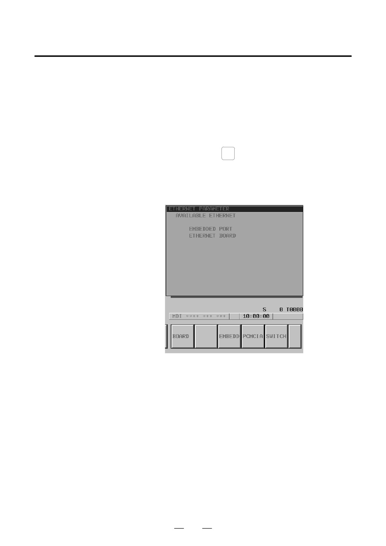
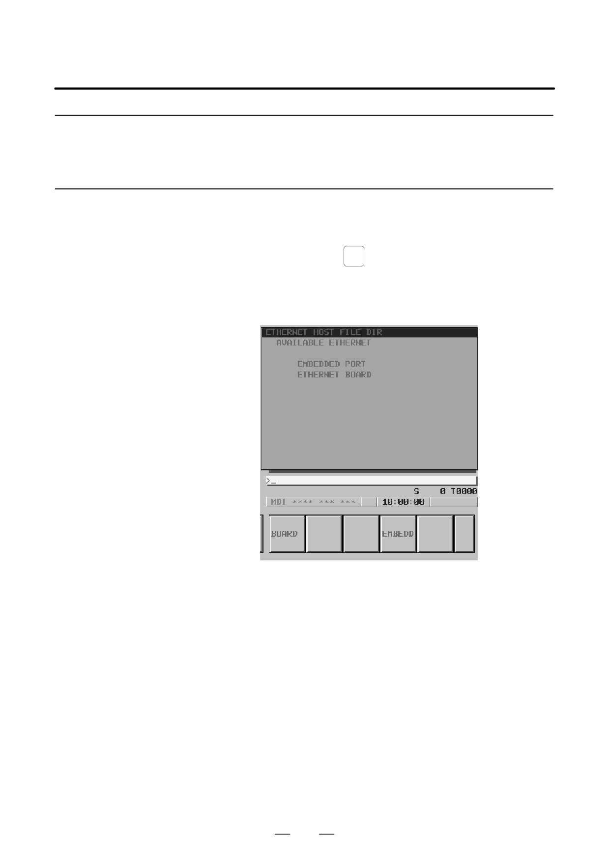
Press the [ETHPRM] soft key. The Ethernet parameter setting screen
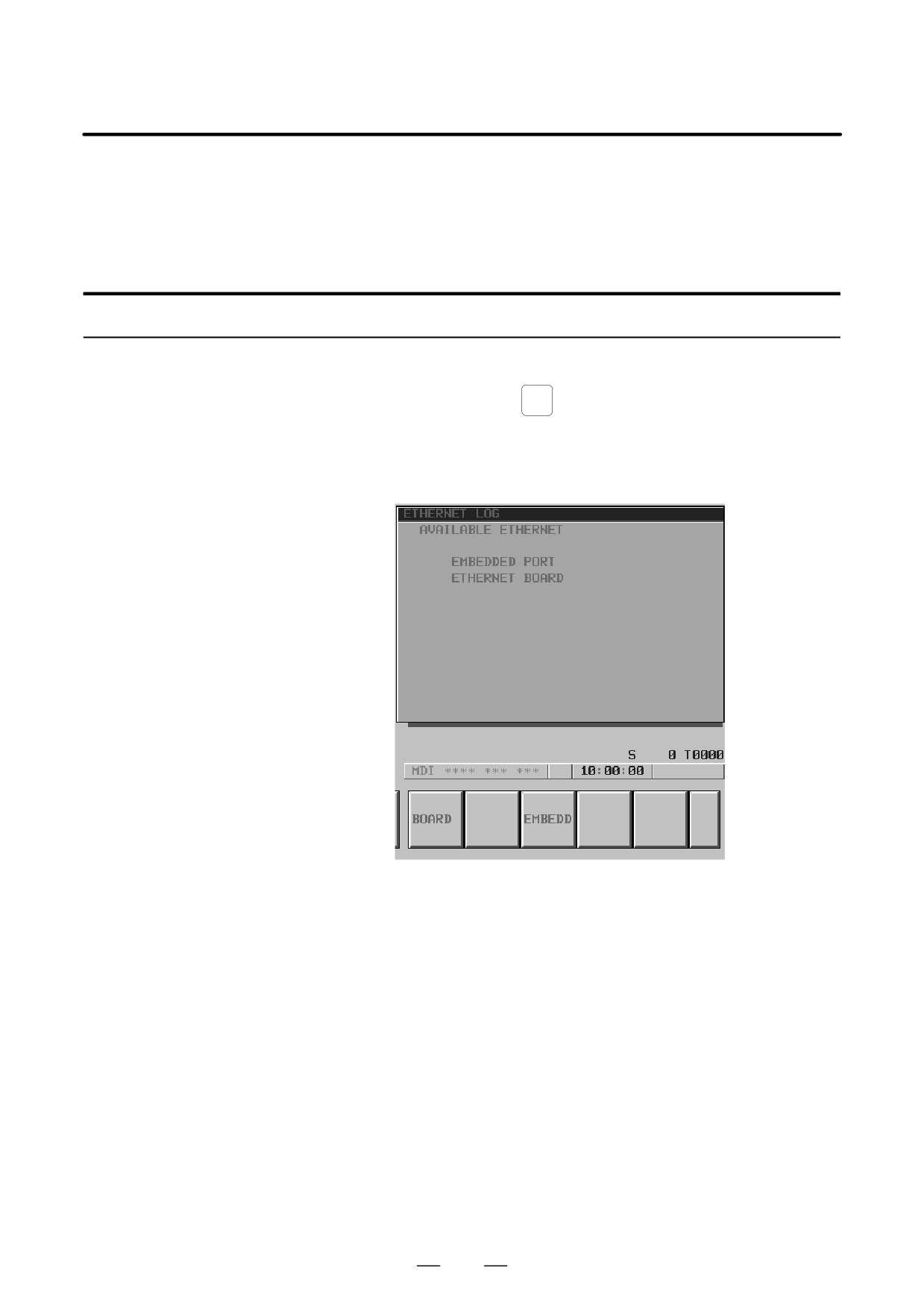
appears. The Ethernet functions currently available are displayed.
The upper row displays the usable embedded Ethernet function
device.
The embedded port or PCMCIA card is displayed.
The lower row displays the usable Ethernet option boards. When no
option board is installed, no information is displayed.
635
8. EMBEDDED ETHERNET FUNCTION
B-63525EN/02
5
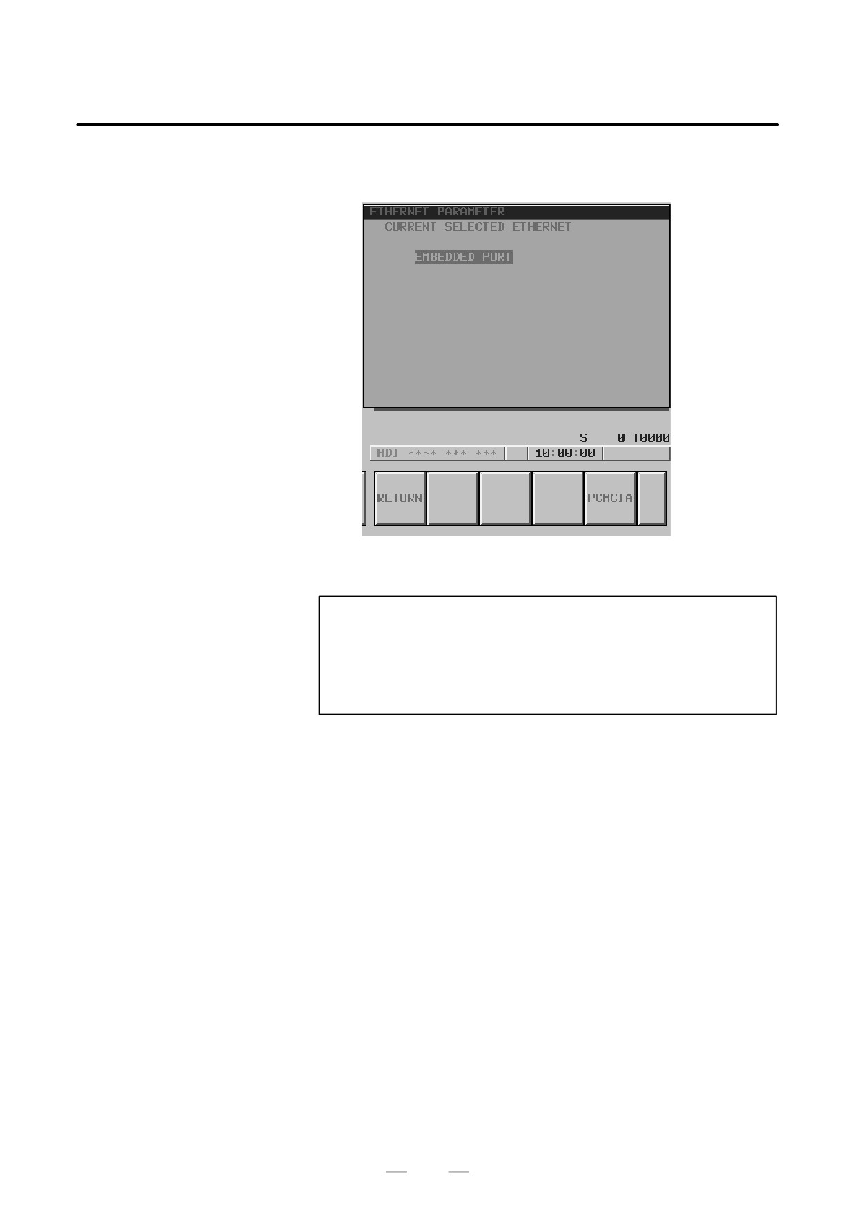
Press the [SWITCH] soft key. The screen for switching between the
embedded Ethernet port and the PCMCIA Ethernet card appears.
6
Press the [PCMCIA] soft key. A confirmation message appears. Press
the [EXEC] soft key to switch the device.
NOTE
Information about the switched device is stored in the
nonvolatile memory.
So, when you turn on the power next time, the previously
selected device can be used directly.
636
B-63525EN/02
8. EMBEDDED ETHERNET FUNCTION
This section describes the operation required of each embedded Ethernet
8.5
function.
EMBEDDED
ETHERNET
OPERATIONS
8.5.1
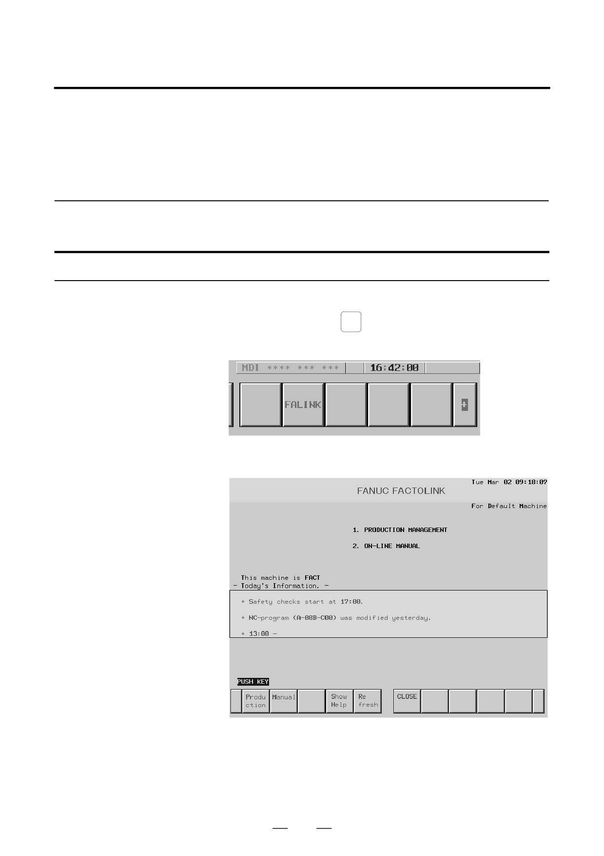
The operation of the FACTOLINK function is described below.
FACTOLINK Function
Display
Procedure
1 Press the function key
MESSAGE
2
Press the continuous menu key at the right end of the soft key display.
3
Press the [FALINK] soft key. The FACTOLINK screen appears.
The screen shown below is a sample FACTOLINK screen.
637
8. EMBEDDED ETHERNET FUNCTION
B-63525EN/02
8.5.2
The operation of the FTP file transfer function is described below.
FTP File Transfer
Function
8.5.2.1
A list of the files held on the hard disk embedded to the host computer is
displayed.
Host file list display
Procedure
1 Press the function key
PROG
2
Press the continuous menu key at the right end of the soft key display.
3
Press the [HOST] soft key. The host file list screen appears. The
Ethernet functions currently available are displayed.
The upper row displays the usable embedded Ethernet function
device.
The embedded port or PCMCIA card is displayed.
The lower row displays the usable Ethernet option boards. When no
option board is installed, no information is displayed.
4
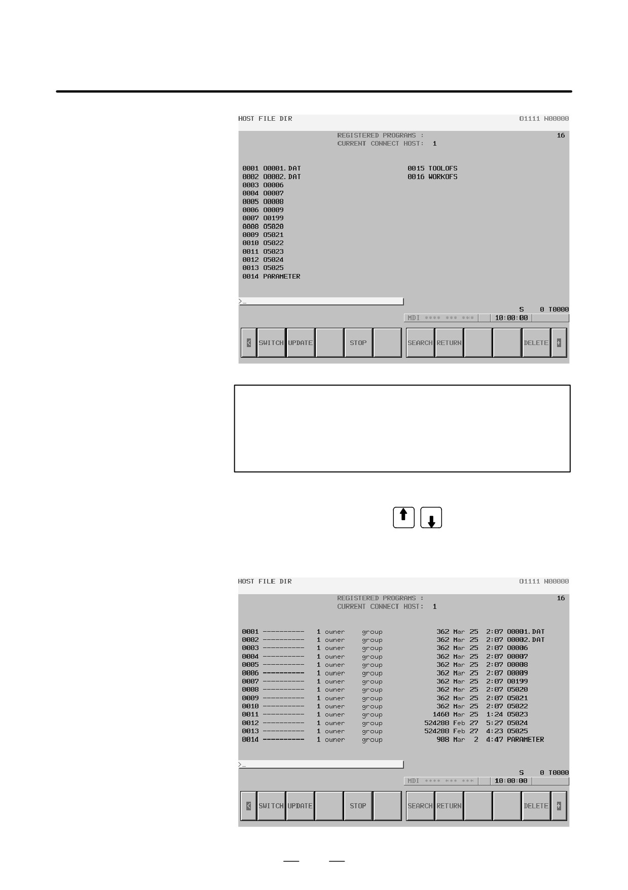
When you press the [EMBEDD] soft key, a list of the files held on the
host computer specified with the embedded Ethernet port is displayed.
If the usable embedded Ethernet function device is the PCMCIA card,
the [PCMCIA] soft key is displayed instead of the [EMBEDD] soft
key. When you press the [PCMCIA] soft key, a list of the files held
on the host computer specified with the PCMCIA Ethernet card is
displayed.
638
B-63525EN/02
8. EMBEDDED ETHERNET FUNCTION
NOTE
Depending on the FTP server software, the number of
displayed programs may differ between the host file list
screen above and the host file list (detail) screen described
below.
5
When a list of files is larger than one page, the screen display can be
PAGE
switched using the page keys
PAGE
6
Press the [UPDATE] soft key to update the screen display.
7
Press the [SWITCH] soft key. The host file list (detail) screen appears.
639

8. EMBEDDED ETHERNET FUNCTION
B-63525EN/02
NOTE
The host file list (detail) screen shown above is an example
of screen display, and information displayed may vary
according to the specification of the FTP server used with
the host computer.
Display items
D Number of registered
The number of files registered in the directory (folder) of the host
program files
computer currently connected is displayed.
D Currently connected
The number of the host currently connected is displayed.
host
List of operations
D SWITCH
This operation switches between normal display and detail display.
D UPDATE
This operation updates information displayed.
D STOP
This operation stops [SEARCH] operation.
D SEARCH
This operation updates screen information so that a file specified by its
file number is placed at the start of the list.
D DELETE
This operation deletes a file held on the hard disk embedded to the host
computer.
D READ
This operation reads a file held on the hard disk embedded to the host
computer to the CNC part program storage. This soft key is displayed
only when 9 is set as the input/output device number of the CNC, and the
CNC is placed in the EDIT mode.
D PUNCH
This operation outputs a file held in the CNC part program storage to the
hard disk embedded to the host computer. This soft key is displayed only
when 9 is set as the input/output device number of the CNC, and the CNC
is placed in the EDIT mode.
640

B-63525EN/02
8. EMBEDDED ETHERNET FUNCTION
8.5.2.2
When a list of the files held on the hard disk embedded to the host
computer is displayed, a file can be placed at the start of the list by
Host file search
specifying its file number.
Procedure
1 Display the host file list screen.
2
Press the [SEARCH] soft key.
3
Type the file number of a file to be displayed at the start of the list with
the MDI keys.
[Input format]
<file-number>
4
Press the [EXEC] soft key.
5
During search, ”SEARCH” blinks in the lower-right corner of the
screen.
A file held on the hard disk embedded to the host computer can be deleted.
8.5.2.3
Host file deletion
Procedure
1 Display the host file list screen.
2
Press the [DELETE] soft key.
3
Type the file number or file name of a file to be deleted, with the MDI
keys.
[Input format]
<file-number>
or
<file-name>
4
Press the [EXEC] soft key.
5
During deletion, ”DELETE” blinks in the lower-right corner of the
screen.
NOTE
1
When a file number is used for deletion, only a file displayed
on the host file list screen can be deleted.
2
The information displayed at the right end of the host file list
(detail) screen is recognized as a file name. So, when
deleting a host file from the host file list (detail) screen by
specifying its file number, check that a file name is displayed
at the right end of the screen, before specifying the file
number.
641
8. EMBEDDED ETHERNET FUNCTION
B-63525EN/02
8.5.2.4
A file (NC program) on the host computer can be read to the CNC
memory.
NC program input
For the host file list screen
Procedure
1 Place the CNC in the EDIT mode.
2
Display the host file list screen.
3
Press the [READ] soft key.
4
Type the file number or file name of an NC program to be input, with
the MDI keys.
[Input format]
<file-number>
or
<file-name>
5
Press the [EXEC] soft key.
6
During input, ”INPUT” blinks in the lower-right corner of the screen.
CAUTION
1
If the CNC memory holds an NC program that has the same
O number as that of an NC program to be input, the NC
program in the CNC memory is overwritten when bit 2 of
parameter No. 3201 is set to 1.
2
If an NC program is input when bit 0 of parameter No. 3201
is set to
1, all NC programs in the CNC memory are
automatically deleted before NC program input.
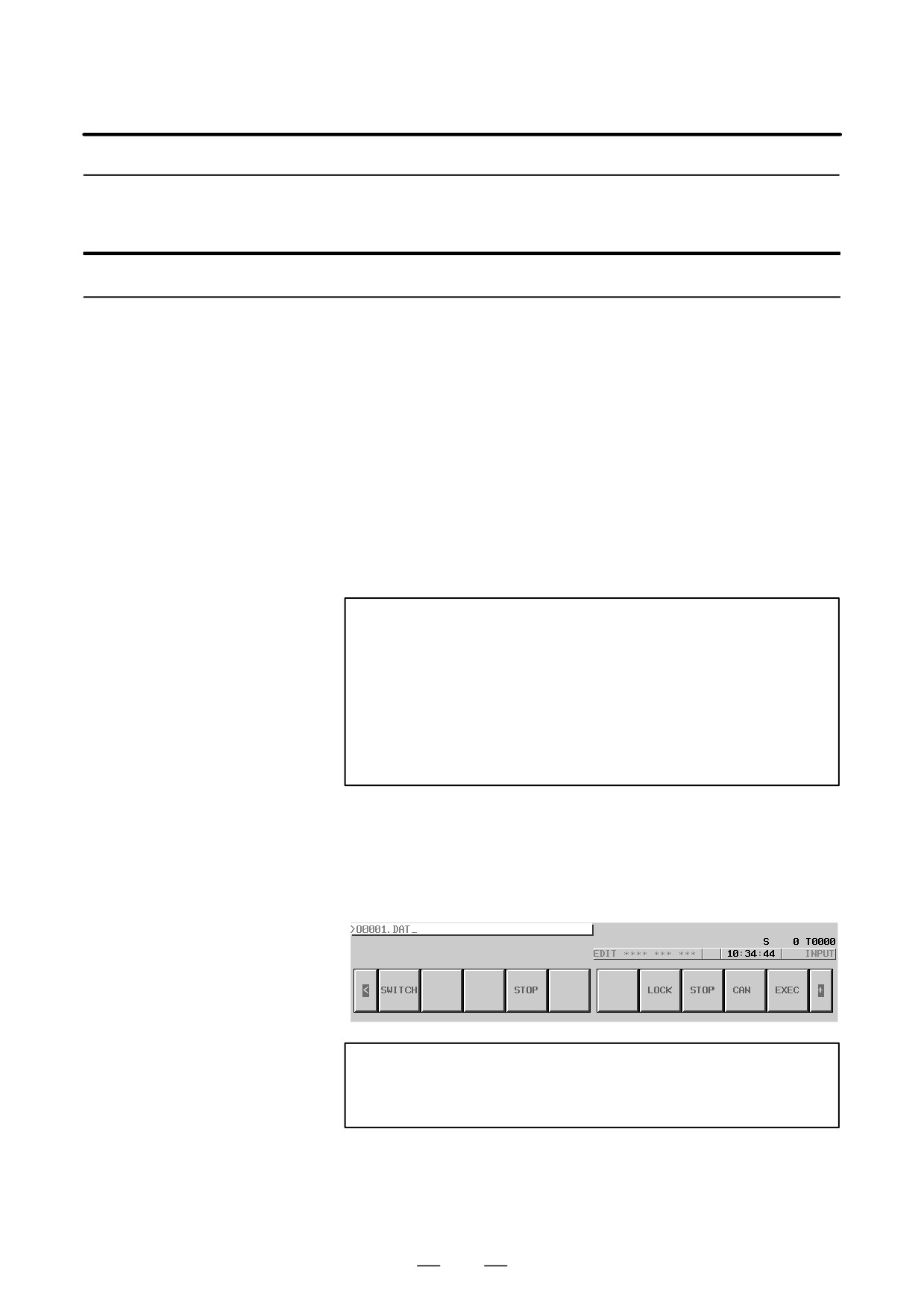
[Example of use]
When a file with the file name O0001.DAT held on the hard disk
embedded to the host computer is to be input to the CNC memory, enter
O001.DAT. Note, however, that the O number input to the CNC memory
depends on the O number described in the file named O0001.DAT.
NOTE
When a file is input from this screen to the CNC memory, the
O number described in the file is input.
642

B-63525EN/02
8. EMBEDDED ETHERNET FUNCTION
For the program screen
Procedure
1 Place the CNC in the EDIT mode.
2
Press the function key
PROG
3
Press the continuous menu key at the right end of the soft key display.
4
Press the [PRGRM] soft key. The program screen appears.
5
Press the [(OPRT)] soft key.
6
Press the continuous menu key at the right end of the soft key display.
7
Press the [READ] soft key.
8
Type the O number of an NC program to be input, with the MDI keys.
[Input format]
<O-number>
9
Press the [EXEC] soft key.
10 During input, ”INPUT” blinks in the lower-right corner of the screen.
CAUTION
1
If the CNC memory holds an NC program that has the same
O number as that of an NC program to be input, the NC
program in the CNC memory is overwritten when bit 2 of
parameter No. 3201 is set to 1.
2
If an NC program is input when bit 0 of parameter No. 3201
is set to
1, all NC programs in the CNC memory are
automatically deleted before NC program input.
NOTE
The valid O number of a file to be input to the CNC memory
is Oxxxx (with xxxx representing a number) only.
8.5.2.5
A file (NC program) in the CNC memory can be output to the host
computer.
NC program output
For the host file list screen
Procedure
1 Place the CNC in the EDIT mode.
2
Display the host file list screen.
3
Press the [PUNCH] soft key.
4
Type the O number of an NC program to be output, with the MDI keys.
[Input format]
<O-number>
643
8. EMBEDDED ETHERNET FUNCTION
B-63525EN/02
5
Press the [EXEC] soft key.
6
During output, ”OUTPUT” blinks in the lower-right corner of the
screen.
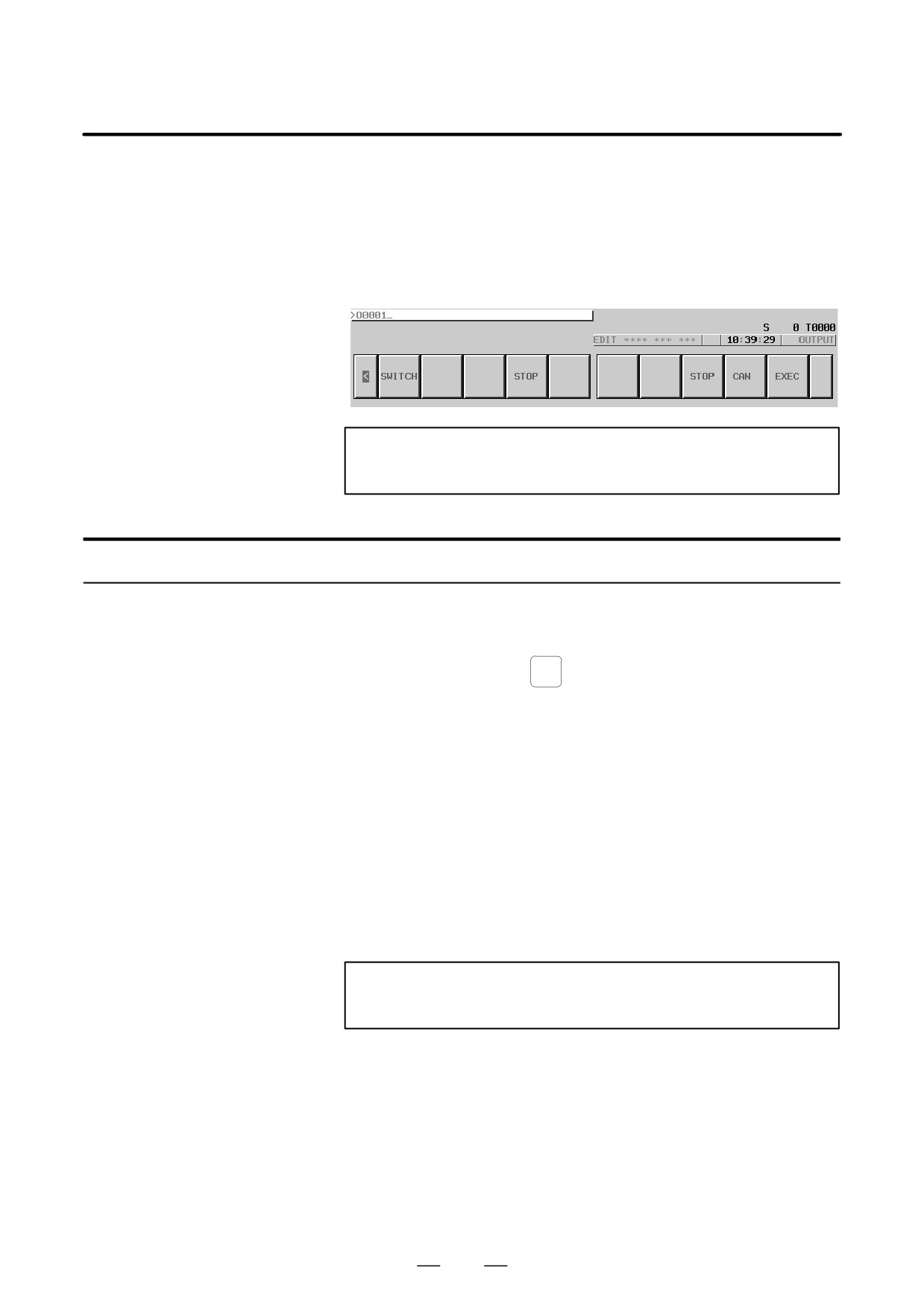
[Example of use]
When an NC program (O0001) in the CNC memory is to be output to the
hard disk embedded to the host computer, enter O0001.
NOTE
An outputted file name is Oxxxx.
For the program screen
Procedure
1 Place the CNC in the EDIT mode.
2
Press the function key
PROG
3
Press the continuous menu key at the right end of the soft key display.
4
Press the [PRGRM] soft key. The program screen appears.
5
Press the [(OPRT)] soft key.
6
Press the continuous menu key at the right end of the soft key display.
7
Press the [PUNCH] soft key.
8
Type the O number of an NC program to be output, with the MDI keys.
[Input format]
<O-number>
9
Press the [EXEC] soft key.
10 During output, ”OUTPUT” blinks in the lower-right corner of the
screen.
NOTE
An outputted file name is Oxxxx.
644

B-63525EN/02
8. EMBEDDED ETHERNET FUNCTION
8.5.2.6
With the FTP file transfer function, the types of data listed below can be
input/output. This subsection describes the input/output method.
Input/output of various
A) NC parameter
types of data
B) Tool offset value
C) Custom macro variable
D) Workpiece offset offset value
E) Pitch error compensation data
F) M code group
G) Operation history data
Parameter input
The file (NC parameter) on the host computer can be input to the CNC
memory.
Procedure
1 Place the CNC in the EDIT mode.
2
Press the function key
SYSTEM
3
Press the continuous menu key at the right end of the soft key display.
4
Press the [PARAM] soft key. The parameter screen appears.
5
Press the [(OPRT)] soft key.
6
Press the continuous menu key at the right end of the soft key display.
7
Press the [READ] soft key.
8
Press the [EXEC] soft key.
9
During input, ”INPUT” blinks in the lower-right corner of the screen.
File name
The fixed file name PRAMETER is used.
File format, restrictions
Refer to the operator’s manual of each CNC.
Parameter output
The file (NC parameter) in the CNC memory can be output to the host
computer.
Procedure
1 Place the CNC in the EDIT mode.
2
Press the function key
SYSTEM
3
Press the continuous menu key at the right end of the soft key display.
4
Press the [PARAM] soft key. The parameter screen appears.
5
Press the [(OPRT)] soft key.
6
Press the continuous menu key at the right end of the soft key display.
7
Press the [PUNCH] soft key.
645

8. EMBEDDED ETHERNET FUNCTION
B-63525EN/02
8
Press the [EXEC] soft key.
9
During output, ”OUTPUT” blinks in the lower-right corner of the
screen.
File name
The fixed file name PRAMETER is used.
File format, restrictions
Refer to the operator’s manual of each CNC.
Tool offset value input
The file (tool offset value) on the host computer can be input to the CNC
memory.
Procedure
1 Place the CNC in the EDIT mode.
OFFSET
2
Press the function key
SETTING
3
Press the continuous menu key at the right end of the soft key display.
4
Press the [OFFSET] soft key. The tool compensation screen appears.
5
Press the [(OPRT)] soft key.
6
Press the continuous menu key at the right end of the soft key display.
7
Press the [READ] soft key.
8
Press the [EXEC] soft key.
9
During input, ”INPUT” blinks in the lower-right corner of the screen.
File name
The fixed file name TOOLOFS is used.
File format, restrictions
Refer to the operator’s manual of each CNC.
Tool offset value output
The file (tool offset value) in the CNC memory can be output to the host
computer.
Procedure
1 Place the CNC in the EDIT mode.
OFFSET
2
Press the function key
SETTING
3
Press the continuous menu key at the right end of the soft key display.
4
Press the [OFFSET] soft key. The tool compensation screen appears.
5
Press the [(OPRT)] soft key.
6
Press the continuous menu key at the right end of the soft key display.
7
Press the [PUNCH] soft key.
8
Press the [EXEC] soft key.
9
During output, ”OUTPUT” blinks in the lower-right corner of the
screen.
646

B-63525EN/02
8. EMBEDDED ETHERNET FUNCTION
File name
The fixed file name TOOLOFS is used.
File format, restrictions
Refer to the operator’s manual of each CNC.
Workpiece origin offset value input
The file (workpiece origin offset value) on the host computer can be input
to the CNC memory.
Procedure
1 Place the CNC in the EDIT mode.
OFFSET
2
Press the function key
SETTING
3
Press the continuous menu key at the right end of the soft key display.
4
Press the [WORK] soft key. The workpiece coordinate system setting
screen appears.
5
Press the [(OPRT)] soft key.
6
Press the continuous menu key at the right end of the soft key display.
7
Press the [READ] soft key.
8
Press the [EXEC] soft key.
9
During input, ”INPUT” blinks in the lower-right corner of the screen.
File name
The fixed file name WORKOFS is used.
File format, restrictions
Refer to the operator’s manual of each CNC.
Workpiece origin offset value output
The file (workpiece origin offset value) in the CNC memory can be output
to the host computer.
Procedure
1 Place the CNC in the EDIT mode.
OFFSET
2
Press the function key
SETTING
3
Press the continuous menu key at the right end of the soft key display.
4
Press the [WROK] soft key. The workpiece coordinate system setting
screen appears.
5
Press the [(OPRT)] soft key.
6
Press the continuous menu key at the right end of the soft key display.
7
Press the [PUNCH] soft key.
8
Press the [EXEC] soft key.
9
During output, ”OUTPUT” blinks in the lower-right corner of the
screen.
File name
The fixed file name WORKOFS is used.
File format, restrictions
Refer to the operator’s manual of each CNC.
647

8. EMBEDDED ETHERNET FUNCTION
B-63525EN/02
Pitch error compensation input
The file (pitch error compensation) on the host computer can be input to
the CNC memory.
Procedure
1 Place the CNC in the EDIT mode.
2
Press the function key
SYSTEM
3
Press the continuous menu key at the right end of the soft key display.
4
Press the [PITCH] soft key. The pitch error setting screen appears.
5
Press the [(OPRT)] soft key.
6
Press the continuous menu key at the right end of the soft key display.
7
Press the [READ] soft key.
8
Press the [EXEC] soft key.
9
During input, ”INPUT” blinks in the lower-right corner of the screen.
File name
The fixed file name PITCH is used.
File format, restrictions
Refer to the operator’s manual of each CNC.
Pitch error compensation output
The file (pitch error compensation) in the CNC memory can be output to
the host computer.
Procedure
1 Place the CNC in the EDIT mode.
2
Press the function key
SYSTEM
3
Press the continuous menu key at the right end of the soft key display.
4
Press the [PITCH] soft key. The pitch error setting screen appears.
5
Press the [(OPRT)] soft key.
6
Press the continuous menu key at the right end of the soft key display.
7
Press the [PUNCH] soft key.
8
Press the [EXEC] soft key.
9
During output, ”OUTPUT” blinks in the lower-right corner of the
screen.
File name
The fixed file name PITCH is used.
File format, restrictions
Refer to the operator’s manual of each CNC.
648

B-63525EN/02
8. EMBEDDED ETHERNET FUNCTION
M code group input
The file (M code group) on the host computer can be input to the CNC
memory.
Procedure
1 Place the CNC in the EDIT mode.
2
Press the function key
SYSTEM
3
Press the continuous menu key at the right end of the soft key display.
4
Press the [M-CODE] soft key. The M code group setting screen
appears.
5
Press the [(OPRT)] soft key.
6
Press the continuous menu key at the right end of the soft key display.
7
Press the [READ] soft key.
8
Press the [EXEC] soft key.
9
During input, ”INPUT” blinks in the lower-right corner of the screen.
File name
The fixed file name M-CODE is used.
File format, restrictions
Refer to the operator’s manual of each CNC.
M code group output
The file (M code group) in the CNC memory can be output to the host
computer.
Procedure
1 Place the CNC in the EDIT mode.
2
Press the function key
SYSTEM
3
Press the continuous menu key at the right end of the soft key display.
4
Press the [M-CODE] soft key. The M code group setting screen
appears.
5
Press the [(OPRT)] soft key.
6
Press the continuous menu key at the right end of the soft key display.
7
Press the [PUNCH] soft key.
8
Press the [EXEC] soft key.
9
During output, ”OUTPUT” blinks in the lower-right corner of the
screen.
File name
The fixed file name M-CODE is used.
File format, restrictions
Refer to the operator’s manual of each CNC.
649

8. EMBEDDED ETHERNET FUNCTION
B-63525EN/02
Operation history data input
The file (operation history data) on the host computer can be input to the
CNC memory.
Procedure
1 Place the CNC in the EDIT mode.
2
Press the function key
SYSTEM
3
Press the continuous menu key at the right end of the soft key display.
4
Press the [OPEHIS] soft key. The operation history screen appears.
5
Press the [(OPRT)] soft key.
6
Press the continuous menu key at the right end of the soft key display.
7
Press the [READ] soft key.
8
Press the [EXEC] soft key.
9
During input, ”INPUT” blinks in the lower-right corner of the screen.
File name
The fixed file name HISTORY is used.
File format, restrictions
Refer to the operator’s manual of each CNC.
Operation history data output
The file (operation history data) in the CNC memory can be output to the
host computer.
Procedure
1 Place the CNC in the EDIT mode.
2
Press the function key
SYSTEM
3
Press the continuous menu key at the right end of the soft key display.
4
Press the [OPEHIS] soft key. The operation history screen appears.
5
Press the [(OPRT)] soft key.
6
Press the continuous menu key at the right end of the soft key display.
7
Press the [PUNCH] soft key.
8
Press the [EXEC] soft key.
9
During output, ”OUTPUT” blinks in the lower-right corner of the
screen.
File name
The fixed file name HISTORY is used.
File format, restrictions
Refer to the operator’s manual of each CNC.
650
B-63525EN/02
8. EMBEDDED ETHERNET FUNCTION
8.5.2.7
The host computer to which the FTP file transfer function attempts to
make a connection as the current communication destination can be
Checking and changing
checked.
of the connection host
Procedure
1 Press the function key
PROG
2
Press the continuous menu key at the right end of the soft key display.
3
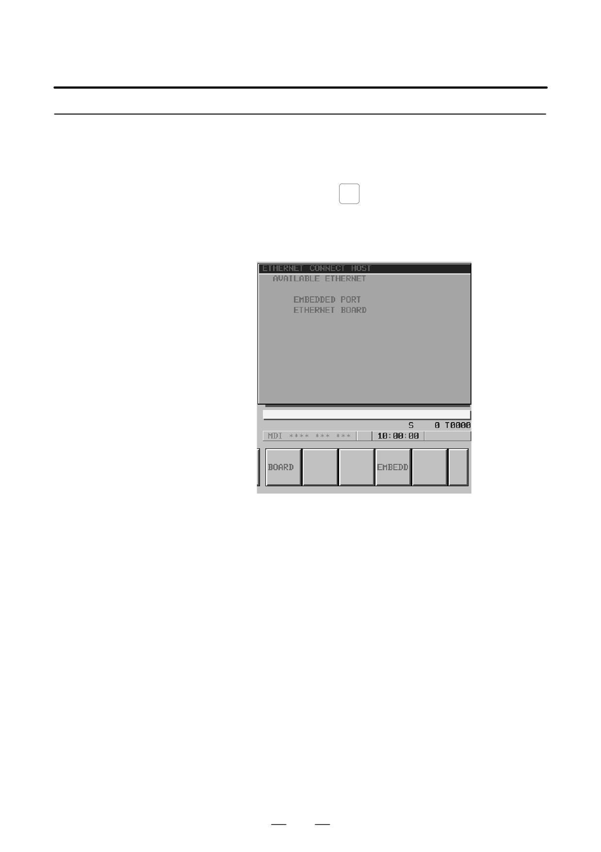
Press the [CONECT] soft key. The connection host change screen
appears. The Ethernet functions currently available are displayed.
The upper row displays the usable embedded Ethernet function
device.
The embedded port or PCMCIA card is displayed.
The lower row displays the usable Ethernet option boards. When no
option board is installed, no information is displayed.
4
When you press the [EMBEDD] soft key, a list of the connection host
computers specified with the embedded Ethernet port is displayed.
If the usable embedded Ethernet function device is the PCMCIA card,
the [PCMCIA] soft key is displayed instead of the [EMBEDD] soft
key. When you press the [PCMCIA] soft key, a list of the connection
host computers specified with the PCMCIA Ethernet card is
displayed.
651
8. EMBEDDED ETHERNET FUNCTION
B-63525EN/02
NOTE
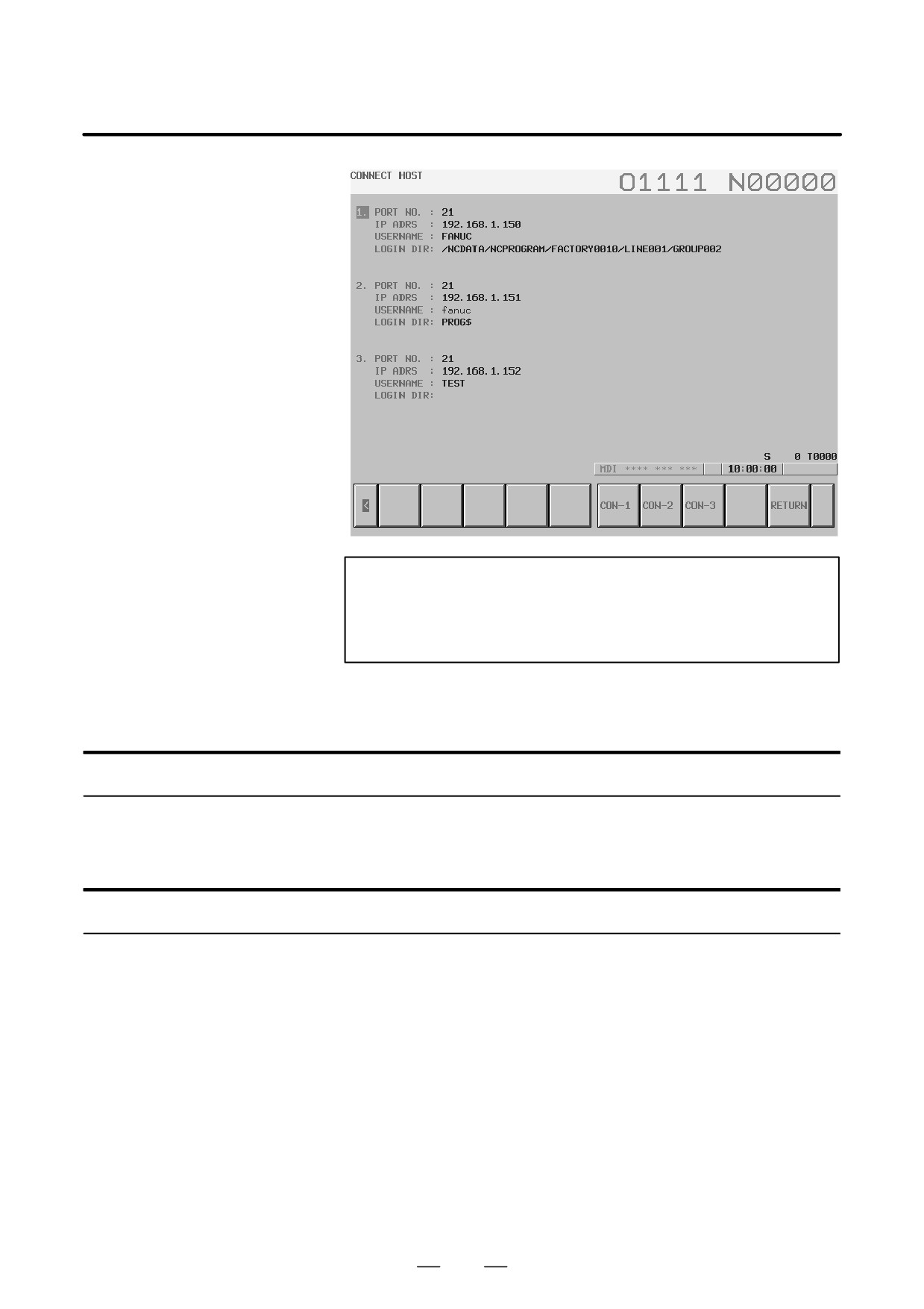
The title of the host computer that is the current
communication destination of the embedded Ethernet is
displayed in reverse video.
5
The connected host can be changed by pressing the [CON-1],
[CON-2], or [CON-3] soft key.
Display items
D Port number, IP address,
Those values that are set on the Ethernet parameter setting screen are
user name, login DIR
displayed.
List of operations
D CON-1
This operation changes the connected host to host 1.
D CON-2
This operation changes the connected host to host 2.
D CON-3
This operation changes the connected host to host 3.
652
B-63525EN/02
8. EMBEDDED ETHERNET FUNCTION
If an error occurs with each function of the embedded Ethernet function,
8.6
the error message screen for the embedded Ethernet function displays an
EMBEDDED
error message.
ETHERNET ERROR
MESSAGE SCREEN
Display
Procedure
1 Press the function key
MESSAGE
2
Press the continuous menu key at the right end of the soft key display.
3
Press the [ETHLOG] soft key. The Ethernet log screen appears. The
Ethernet functions currently available are displayed.
The upper row displays the usable embedded Ethernet function
device.
The embedded port or PCMCIA card is displayed.
The lower row displays the usable Ethernet option boards. When no
option board is installed, no information is displayed.
4
By pressing the [EMBEDD] soft key or the [PCMCIA] soft key, the
error message screen for the embedded Ethernet function can be
displayed.
The error message screen does not differ between the embedded
Ethernet port and PCMCIA Ethernet card. The same screen is shared.
653
8. EMBEDDED ETHERNET FUNCTION
B-63525EN/02
PAGE
5
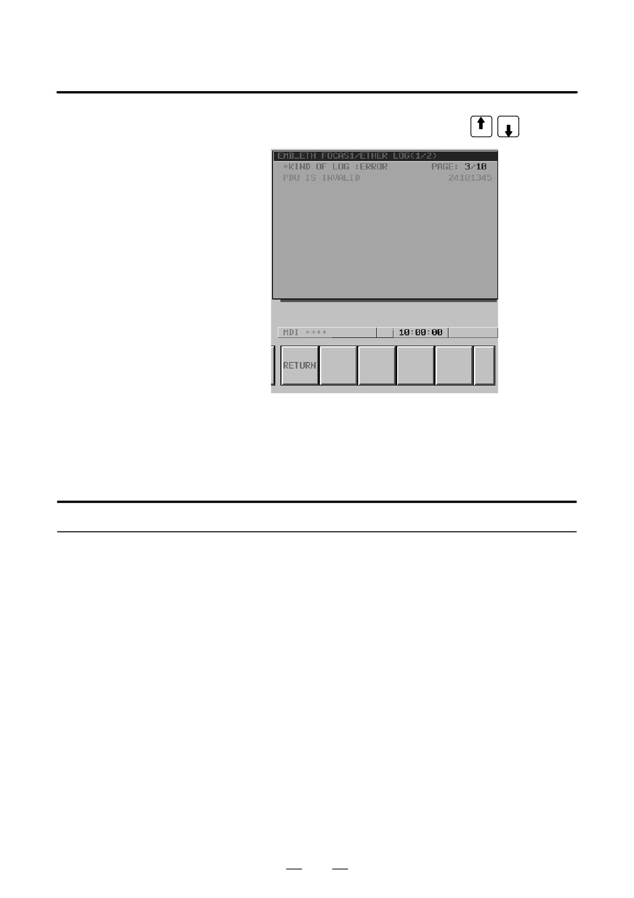
Switch the screen display with the page keys
PAGE
[Tip]
The latest error message is displayed at the top of the screen. To the right
of an error message, the date and time data of the occurrence of the error
is displayed. The format of date and time data is ddhhmmss where dd
represents a day, hh represents hours, mm represents minutes, and ss
represents seconds.
Configuration
The embedded Ethernet log screen consists of the screens below.
(1) EMB_ETH MASTER CTRL LOG screen (2 screens)
Log screen used to set the parameters of the embedded Ethernet
function and display error messages at the time of embedded Ethernet
initialization
(2) EMB_ETH FOCAS1/ETHER LOG screen (2 screens)
Log screen used to display error messages related to the
FOCAS1/Ethernet function (DNC1/Ethernet function)
(3) EMB_ETH PMC LOG screen (2 screens)
Log screen used to display error messages related to the PMC online
monitor functions such as FANUC LADDER-III
(4) EMB_ETH FACTOLINK LOG screen (2 screens)
Log screen used to display error messages related to the FACTOLINK
function
(5) EMB_ETH FTP TRANSFER LOG screen (2 screens)
Log screen used to display error messages related to the FTP file
transfer function
654
B-63525EN/02
8. EMBEDDED ETHERNET FUNCTION
With the embedded Ethernet function, a dedicated maintenance screen is
8.7
available.
EMBEDDED
The maintenance screen enables operations to be checked when the
ETHERNET
embedded Ethernet function operates abnormally.
MAINTENANCE
SCREEN
Display
Procedure
1 Press the function key
SYSTEM
2
Press the continuous menu key at the right end of the soft key display.
3
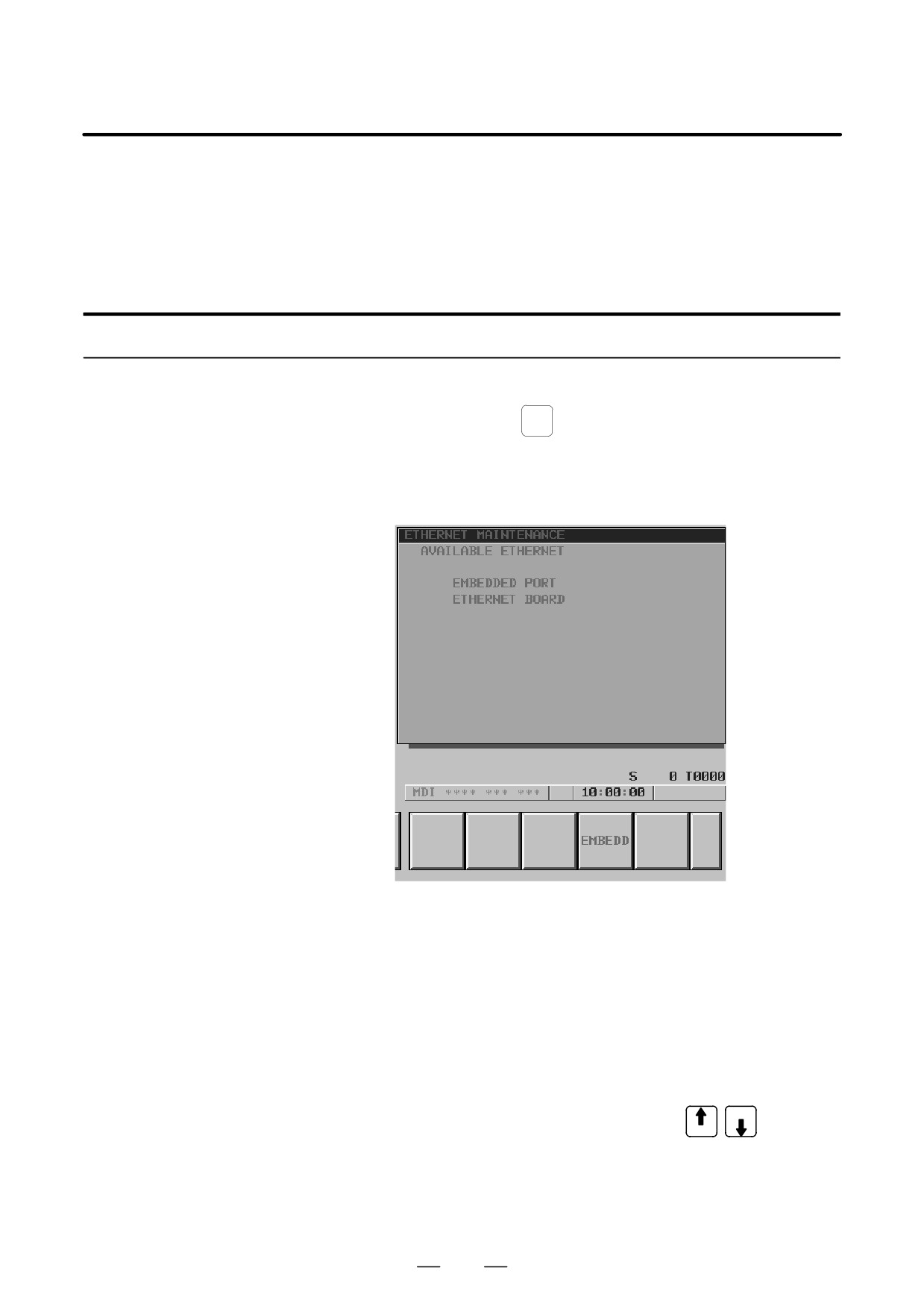
Press the [ETHMNT] soft key. The Ethernet maintenance screen
appears. The Ethernet functions currently available are displayed.
The upper row displays the usable embedded Ethernet function
device.
The embedded port or PCMCIA card is displayed.
The lower row displays the usable Ethernet option boards. When no
option board is installed, no information is displayed.
4
By pressing the [EMBEDD] soft key or the [PCMCIA] soft key, the
maintenance screen for the embedded Ethernet function can be
displayed.
The maintenance screen does not differ between the embedded
Ethernet port and PCMCIA Ethernet card. The same screen is shared.
PAGE
5
Switch the screen display with the page keys
PAGE
655
8. EMBEDDED ETHERNET FUNCTION
B-63525EN/02
6
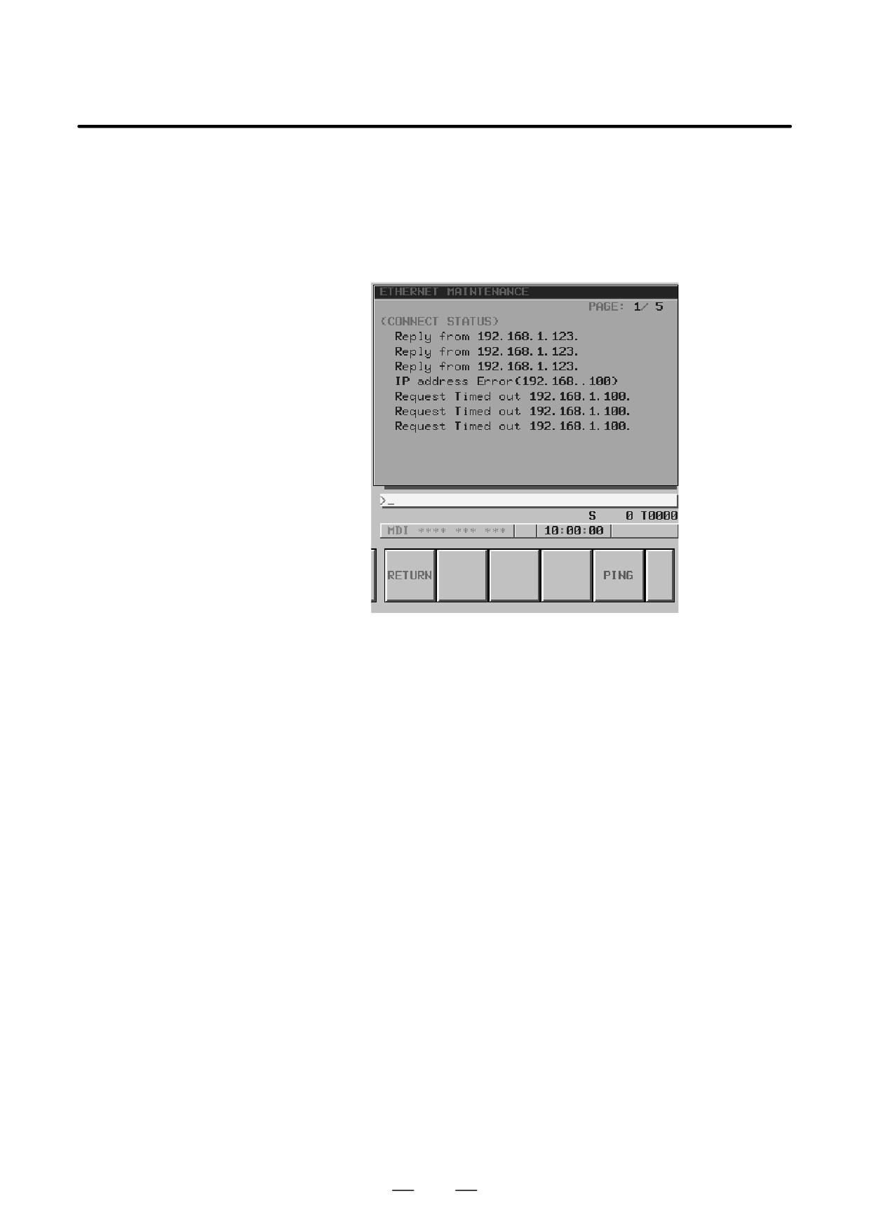
The screen below is used to check the state of the communication cable
and whether a communication destination exists.
Enter the IP address of a communication destination through MDI
keys, then press the [PING] soft key. Communication is performed
three times with the specified communication destination, and the
results are displayed.
Messages displayed:
Reply from IP-address
This message indicates that a response was received from the
specified communication destination and that the specified
communication destination exists on the network.
Request Timed out IP-address
This message indicates that no response was received from the
specified communication destination and that the specified
communication destination does not exist on the network.
Check if the power to the communication destination
equipment is turned on. Check also the parameter settings and
network installation for errors.
IP address Error (IP-address)
The specified IP address is incorrect. Check the entered IP
address.
656
B-63525EN/02
8. EMBEDDED ETHERNET FUNCTION
7
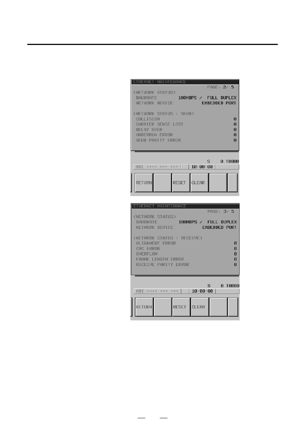
The screen below is used to check the communication state of the
embedded Ethernet function and the error detection count of the
Ethernet controller.
The screen consists of two pages: one page for an error detection count
for transmission, and the other for an error detection count for
reception.
By pressing the [CLEAR] soft key, the error detection counters for
transmission and reception can be cleared to 0.
By pressing the [RESET] soft key, the current communication device
can be initialized and communication can be performed from the
initial state. Use this key to reset communication based on the
embedded Ethernet function.
657
8. EMBEDDED ETHERNET FUNCTION
B-63525EN/02
8
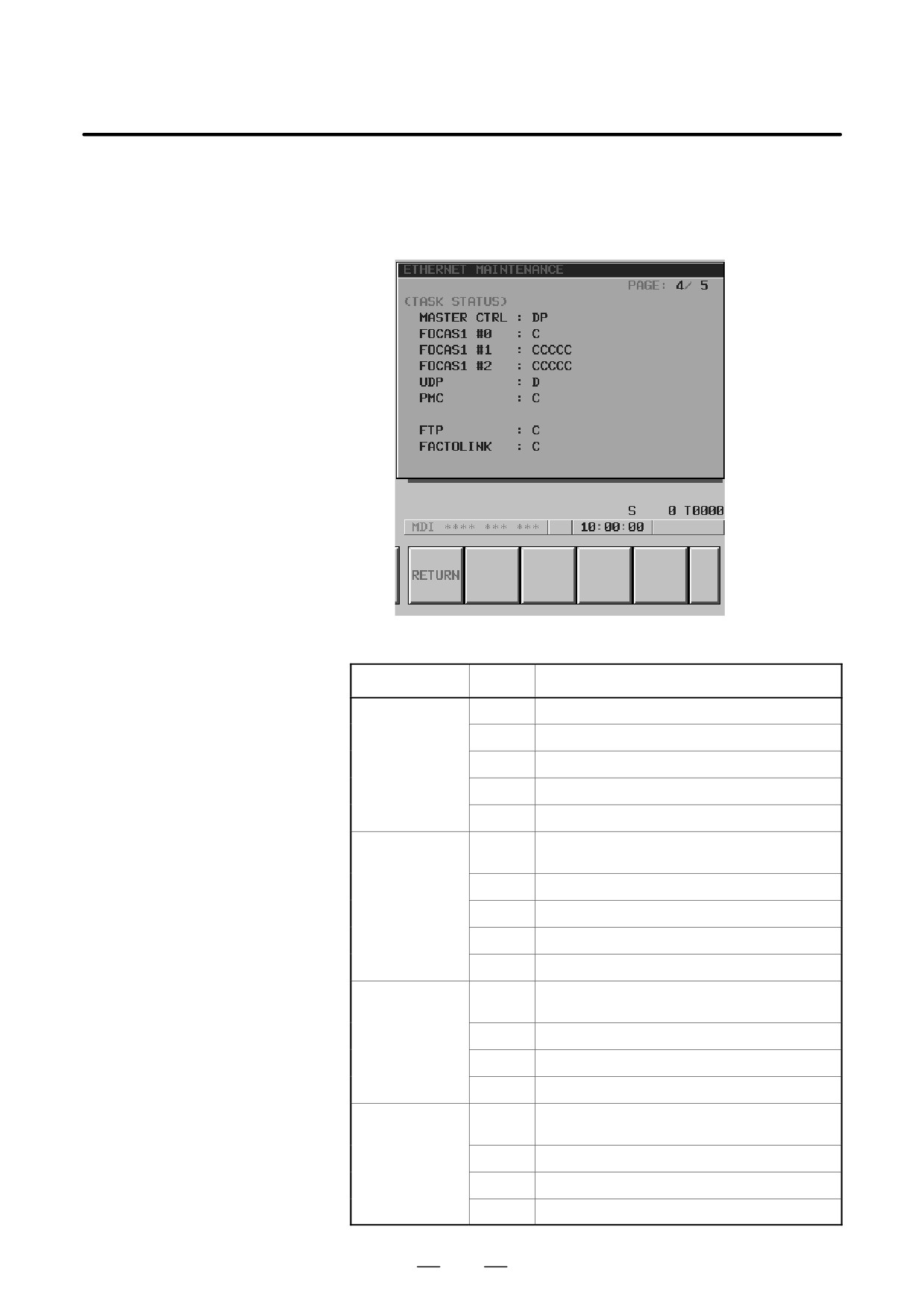
The screen below is used to check the state of each task of the
embedded Ethernet function.
Symbol
Meaning
MASTER CTRL
E
Ethernet controller being initialized
D
Data being processed(NOTE)
W
Waiting for data processing(NOTE)
P
Waiting for parameter setting
S
Parameters being set
FOCAS1 #0
X
Waiting for completion of Ethernet controller initializa-
tion
E
Being activated
C
Waiting for connection from the personal computer
O
Connection being processed
N
FOCAS1/Ethernet execution disabled
FOCAS1 #1,#2
X
Waiting for completion of Ethernet controller initializa-
tion
C
Waiting for connection from the personal computer
D
Data being processed(NOTE)
W
Waiting for data processing(NOTE)
UDP
X
Not executed yet. Waiting for completion of Ethernet
controllerinitialization.
E
Being activated
D
Data being processed(NOTE)
W
Waiting for data processing(NOTE)
658
B-63525EN/02
8. EMBEDDED ETHERNET FUNCTION
Symbol
Meaning
PMC
X
Waiting for completion of Ethernet controller initializa-
tion
D
Data being processed(NOTE)
W
Waiting for data processing(NOTE)
FTP
X
Waiting for completion of Ethernet controller initializa-
tion
D
Data being processed(NOTE)
W
Waiting for data processing(NOTE)
FACTOLINK
X
Waiting for completion of Ethernet controller initializa-
tion
D
Data being processed(NOTE)
W
Waiting for data processing(NOTE)
NOTE
A state change occurs between the states ”Data being
processed” and ”Waiting for data processing” even when
communication is not performed actually.
9
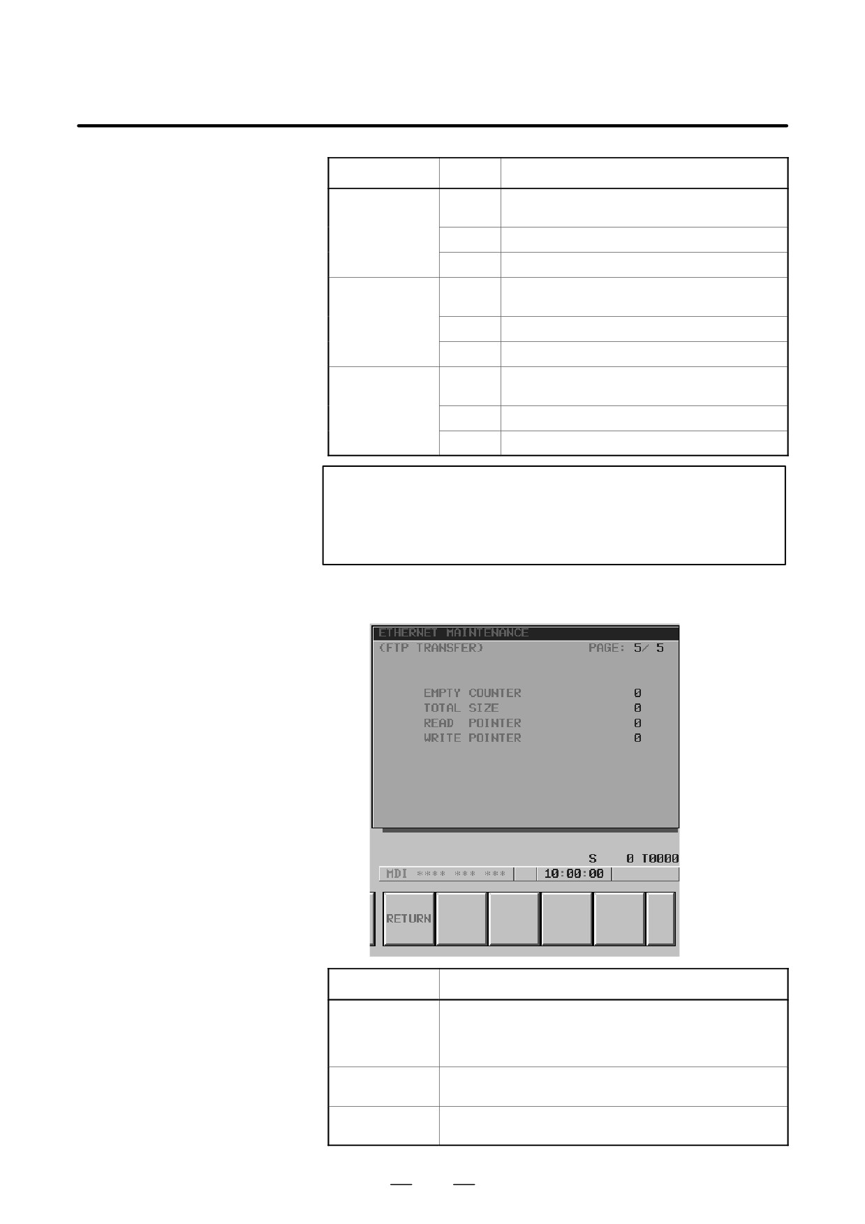
Information about the interface between the FTP file transfer function
and CNC is displayed.
Item
Description
EMPTY
Indicates a buffer empty count during NC program transfer from
COUNTER
the FTP file transfer function to the CNC.
This counter is initialized to 0 at power-on, then is incremented
each time a certain condition is satisfied.
TOTAL SIZE
Indicates the total number of bytes transferred when one NC pro-
gram is transferred using the FTP file transfer function.
READ POINTER
Indicates internal buffer management information when the FTP file
WRITE POINTER
transfer function is used.
659

8. EMBEDDED ETHERNET FUNCTION
B-63525EN/02
This section describes troubleshooting and check items associated with
8.8
the embedded Ethernet function.
TROUBLESHOOTING
8.8.1
1) Is an STP cable used for connection between the hub and embedded
Ethernet?
Check Items Related to
2) Is the STP cable connected correctly?
Connection with the
In general, a straight cable is used for connection between the hub and
Hub
communication device.
3) Is the power to the hub turned on?
4) The PCMCIA Ethernet card is used only with 10BASE-T. Is a hub
for 10BASE-T used when the PCMCIA Ethernet card is used?
5) Is the link LED turned on when the embedded Ethernet port is used?
The link LED is not turned on when the hub is not connected or the
power to the hub is not turned on.
6) Is the LED (for link display) of the connected hub turned on?
(Some hubs are not provided with a link LED.)
The LED is not turned on when the hub is not connected with the
embedded Ethernet or the power to the CNC is not turned on.
8.8.2
This subsection can be ignored when a network is built only with a hub
to which the embedded Ethernet is connected.
Check Items Related to
The general check items are listed below. For network installation,
Connection with a
consult with vendors specialized in this area. Install cables away from
Backbone
noise sources.
When a 10BASE-5 backbone is used
1) Are transceivers connected to the backbone cable correctly?
S If the transceivers are connected correctly, the resistance between
the backbone shield and central conductor is about 25 ohms (when
terminating resistors are attached).
S A special tool may be required for transceiver installation.
(The
special tool varies from one vendor to another. For details, refer to
the relevant manual of each vendor.)
S At a location where a transceiver was once installed, do not install
a transceiver again. (The backbone cable can be damaged.)
2) Are transceivers installed at correct intervals?
S Transceivers need to be spaced from each other by 2.5 m or more.
It is recommended that transceivers be installed at intervals of an
integral multiple of 2.5 m. Usually, installation locations are
marked on a backbone cable.
3) Are terminating resistors attached?
S A terminating resistor (50 ohms) needs to be attached to each end
of the backbone cable.
660

B-63525EN/02
8. EMBEDDED ETHERNET FUNCTION
4) Is the length of the backbone cable 500 m or less?
5) Does the cable (transceiver cable) connecting a hub to a transceiver
satisfy the specified length?
S Usually, the maximum allowable length of a transceiver cable is 50
m. However, the maximum allowable length of some thin cables
may be less than 50 m. Check the specification of the cable.
When a 10BASE-2 backbone is used
1) Is the length of one cable 0.5 m or more?
S The minimum allowable span between nodes (devices) is 0.5 m.
2) Is the length of the backbone cable (total length of the cables) 185 m
or less?
3) Are terminating resistors attached?
S A terminating resistor (50 ohms) needs to be attached to each end
of the backbone cable.
8.8.3
This subsection describes how to check the minimum settings required
for communication.
Checking the Setting of
Each Parameter
Checking the settings on the embedded Ethernet side
1) Is the MAC address of the embedded Ethernet displayed?
S The MAC address of a embedded Ethernet port is set for each CNC,
and can be checked on the parameter setting screen.
S A unique MAC address is assigned to each PCMCIA Ethernet card.
When a PCMCIA Ethernet card is selected and inserted, MAC
address display is provided.
2) Is a correct IP address set?
S Check if an IP address already specified for another device is set.
3) Is a correct subnet mask set?
S The subnet mask setting must match the subnet mask setting on the
communication destination device.
4) Is a correct router IP address set when communication via a router is
performed?
Checking the settings on the personal computer side
1) Is a correct IP address set?
S Check if an IP address already specified for another device is set.
2) Is a correct subnet mask set?
S The subnet mask setting must match the subnet mask setting on the
communication destination device.
3) Is a correct router IP address set when communication via a router is
performed?
661