FANUC Series 16i/160i/160is-MODEL B, Series 18i/180i/180is-MODEL B, Series 21i/210i/210is-MODEL B. MAINTENANCE MANAUL - page 22
8. EMBEDDED ETHERNET FUNCTION
B-63525EN/02
H Absolute position
H Relative position
H Machine position
H Remaining travel amount
H Actual speed
D
NC program
D
Part program storage directory information
D
NC data file
H Parameter
H Tool offset value
H Custom macro variable
H Workpiece origin offset
H Setting data
H P code macro variable
H Pitch error compensation
D
Tool life management data
D
History data
H Operation history data
H Alarm history data
D
Servo-/spindle-related data
D
Data related to waveform diagnosis
D
Modal data
D
Diagnosis data
D
A/D conversion data
D
Alarm information
D
NC system identification information
D
PMC data
H Addresses G, F, Y, X, A, R, T, K, C, D
H Extended nonvolatile data
Remote operation
From the personal computer, the following operations can be performed:
D NC program selection
D NC program deletion
D External reset
NOTE
With the FOCAS1/Ethernet function of the embedded
Ethernet function, DNC operation cannot be performed.
602

B-63525EN/02
8. EMBEDDED ETHERNET FUNCTION
8.2.3
The DNC1/Ethernet function allows a personal computer to remotely
control and monitor the CNC. The DNC1/Ethernet function provides
DNC1/Ethernet
software libraries in a simpler function call format when compared with
Function
the FOCAS1/Ethernet function.
For details, refer to “FANUC Personal Computer FA System Windows
NT Version OPERATOR’S MANUAL (B-75044EN)”.
NC data transfer
The following NC data can be transferred by operations on the personal
computer:
D NC program
D Part program storage directory information
D NC file data
H Parameter
H Tool offset value
H Custom macro variable
D Alarm information
D NC system identification information
D PMC data
H Addresses G, F, Y, X, A, R, T, K, C, D
Remote operation
From the personal computer, the following operations can be performed:
D NC program selection
D NC program deletion
D External reset
NOTE
With the DNC1/Ethernet function of the embedded Ethernet
function, DNC operation cannot be performed.
603
8. EMBEDDED ETHERNET FUNCTION
B-63525EN/02
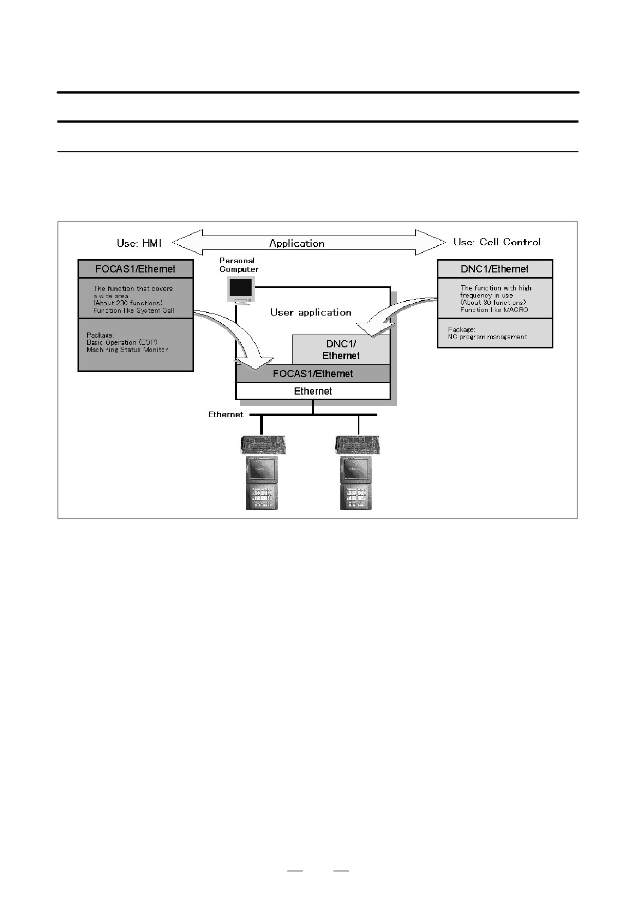
Differences between the FOCAS1/Ethernet function and DNC1/Ethernet function
Compared with the FOCAS1/Ethernet function, the DNC1/Ethernet
function provides software libraries in a simpler function call format for
frequently used functions.
604

B-63525EN/02
8. EMBEDDED ETHERNET FUNCTION
8.2.4
The FTP file transfer function transfers files with FTP. The function can
read and punch NC programs and various types of NC data.
FTP File Transfer
Function
NOTE
The FTP file transfer function is usable with the control
software for the embedded Ethernet function series 656A
edition 02 or later.
NC data transfer
The following NC data can be transferred by operations on the NC:
[Personal computer ²³
D NC program
Part program storage]
D NC file data
H Parameter
H Tool offset value
H Workpiece origin offset value
H Pitch error compensation
H M code group (Series 16i/18i/160i/180i/160is/180is-B only)
D History data
H Operation history data
8.2.5
The table below indicates the differences between the embedded Ethernet
function and the Ethernet function based on the option board.
Functional Differences
between the Embedded
Ethernet Function and
Embedded Ethernet
Option board
the Ethernet Function
FOCAS1/Ethernet function
Available
Available
Based on the Option
CNC screen display function
Not available
Available
Board
DNC operation
Not available
Available
Data Server function
Not available (Note 1)
Available
FACTOLINK function
Available
Available
605

8. EMBEDDED ETHERNET FUNCTION
B-63525EN/02
NOTE
1
The embedded Ethernet function includes the FTP file
transfer function.
This function is almost equivalent to the NC data transfer
function in the FTP mode of the Data Server function of the
option board.
2
Compared with the option board, the embedded Ethernet
function allows a smaller number of FOCAS1/Ethernet
clients to be connected simultaneously.
Embedded
Ethernet
Fast Ether-
Ethernet
board
net board
Number of clients that can be
5 clients
10 clients
20 clients
connected simultaneously
maximum
maximum
maximum
Number of personal computers
1 unit (recom-
10 units
20 units
that can be connected simulta-
mended)
maximum
maximum
neously
3
Communications using the embedded Ethernet function is
processed by the CPU of the CNC. This means that the
operation state of the CNC can affect the performance of
communication based on the embedded Ethernet function,
and communication based on the embedded Ethernet
function can affect the processing of the CNC.
The embedded Ethernet function has lower priority than
axis-by-axis processing such as automatic operation
processing and manual operation. So, when automatic
operation is being performed or many controlled axes are
involved, communication may become slower.
On the contrary, the embedded Ethernet function has
higher priority over CNC screen display processing, C
language executor processing (excluding high-level tasks),
and macro executor processing
(excluding execution
macros). So, communication based on the embedded
Ethernet function can decrease the performance of such
processing.
4
Note that when the embedded Ethernet function is
connected to an intranet that handles large volumes of
broadcast data, for example, the processing of broadcast
data can take a longer time, resulting in a decrease in
performance of processing such as CNC screen display
processing.
606

B-63525EN/02
8. EMBEDDED ETHERNET FUNCTION
This section describes the setting of the parameters for the embedded
8.3
Ethernet function for the Series 16i/18i/21i/160i/180i/210i/160is/180is/
SETTING THE
210is-B.
EMBEDDED
ETHERNET
FUNCTION
This subsection describes the settings required to operate the
8.3.1
FACTOLINK function when the embedded Ethernet function for the
Parameter Setting of
Series 16i/18i/21i/160i/180i/210i/160is/180is/210is-B is used.
the FACTOLINK
Function
8.3.1.1
Notes on using the
CAUTION
FACTOLINK function for
When using the embedded Ethernet function for the first
the first time
time, make various settings including IP address setting
carefully and conduct a communication test sufficiently,
consulting with your network manager.
Note that if an incorrect IP address is set, for example, the
entire network may suffer from a communication error.
NOTE
1
When the FACTOLINK function is used, the optional
function corresponding to a CNC used is required.
Series16i-TB
A02B-0281-S708
Series 16i-MB
A02B-0282-S708
Series 18i-TB
A02B-0283-S708
Series 18i-MB
A02B-0284-S708
Series 21i-TB
A02B-0285-S708
Series 21i-MB
A02B-0286-S708
2
With the FACTOLINK function, only one FACTOLINK server
can be connected to one CNC.
607
8. EMBEDDED ETHERNET FUNCTION
B-63525EN/02
8.3.1.2
On the Ethernet parameter setting screen, set the parameters for operating
the FACTOLINK function.
FACTOLINK parameter
setting screen
Display
Procedure
1
Place the CNC in the MDI mode.
2
Press the function key
SYSTEM
3
Press the continuous menu key at the right end of the soft key display.
4
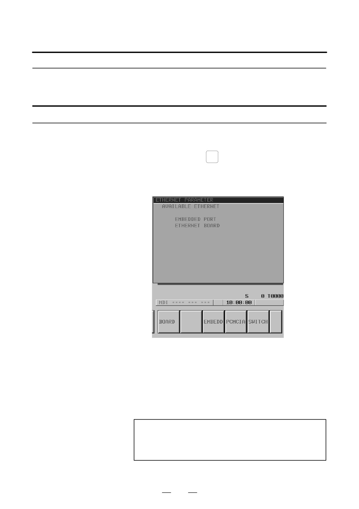
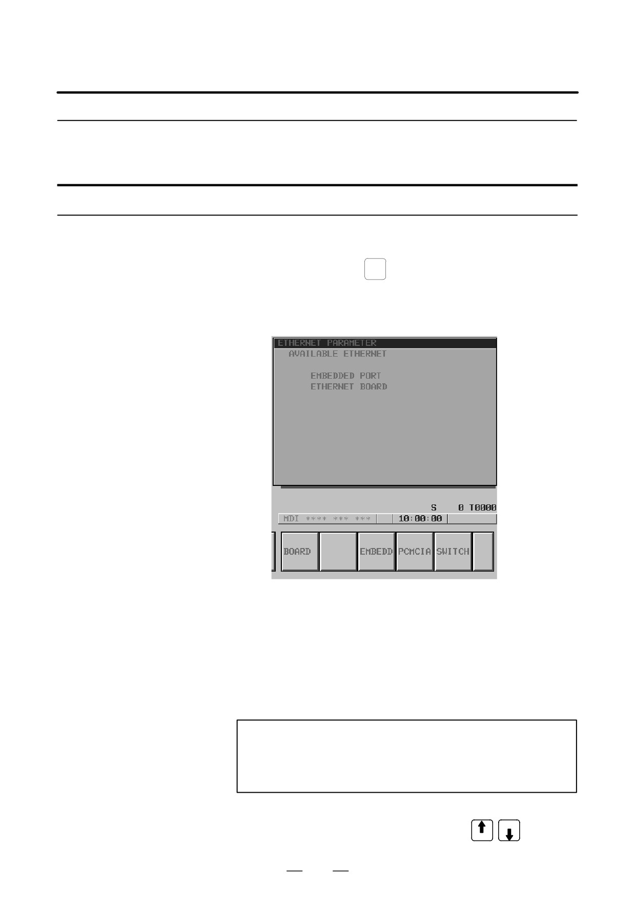
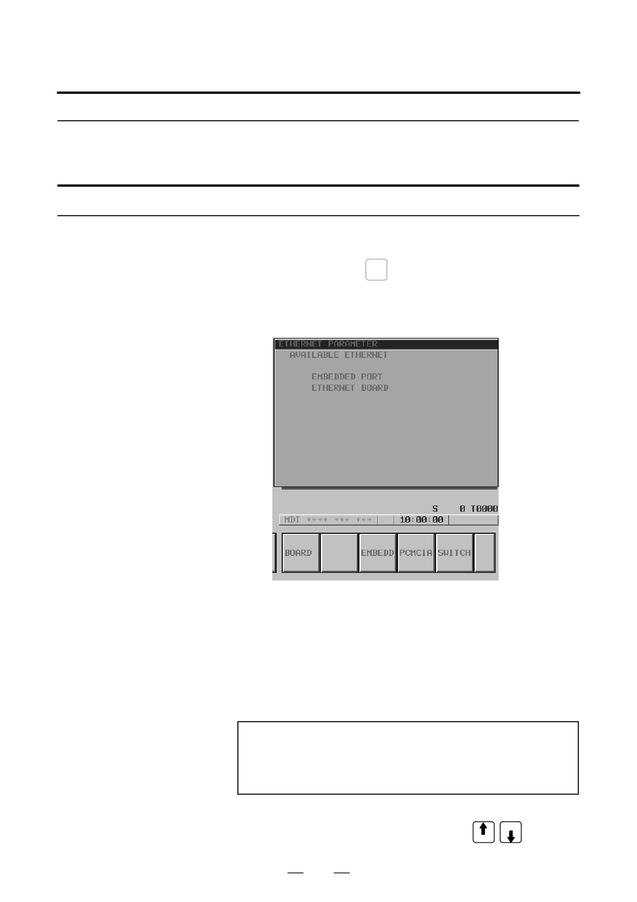
Press the [ETHPRM] soft key. The Ethernet parameter setting screen
appears. The Ethernet functions currently available are displayed.
The upper row displays the usable embedded Ethernet function
device.
The embedded port or PCMCIA card is displayed.
The lower row displays the usable Ethernet option boards. When no
option board is installed, no information is displayed.
5
By pressing the [EMBEDD] soft key, the parameters for the embedded
Ethernet port can be set.
By pressing the [PCMCIA] soft key, the parameters for the PCMCIA
Ethernet card can be set.
NOTE
The parameters for the embedded Ethernet port and the
parameters for the PCMCIA Ethernet card are independent
of each other.
6
By using the MDI keys and soft keys, enter and update data.
608
B-63525EN/02
8. EMBEDDED ETHERNET FUNCTION
PAGE
7
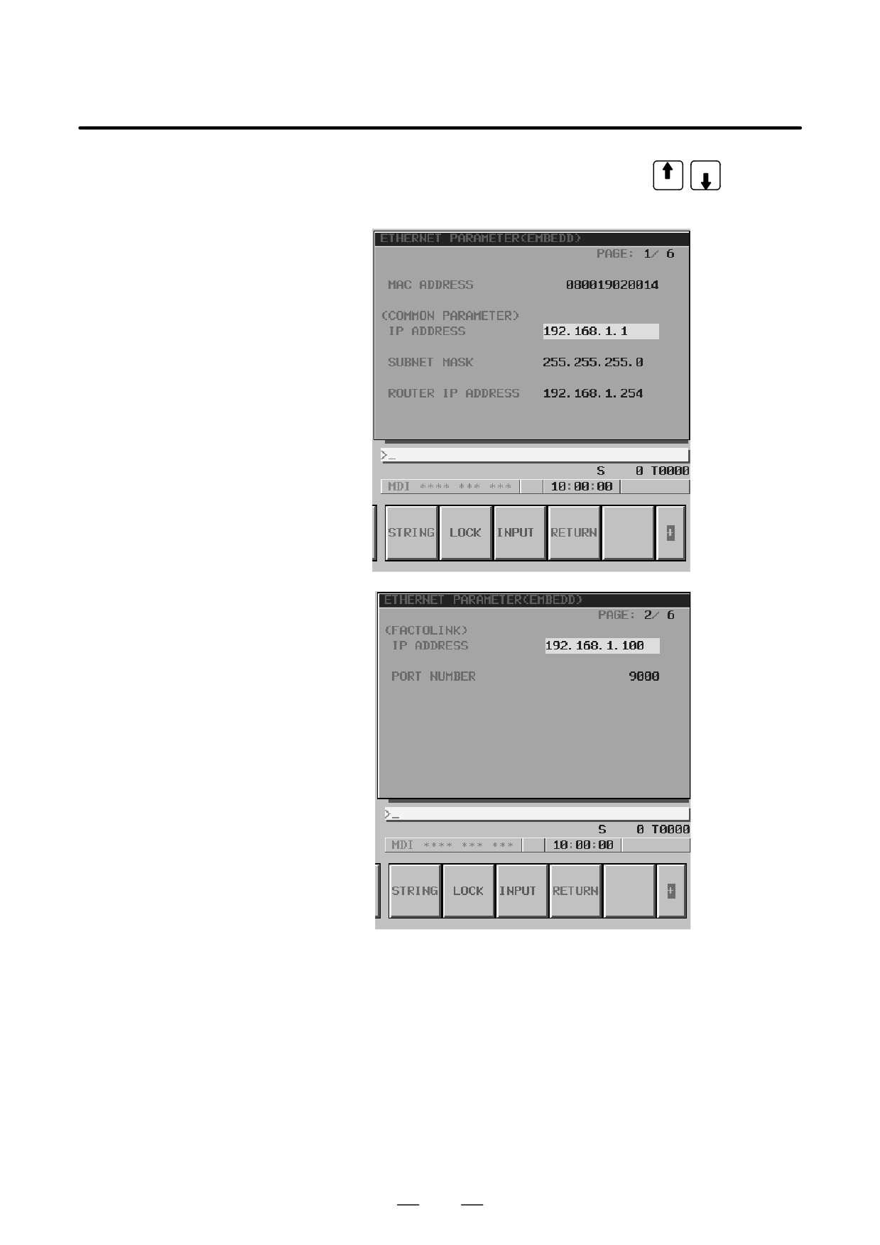
Switch the screen display with the page keys
PAGE
If data is already registered, the data is displayed.
609

8. EMBEDDED ETHERNET FUNCTION
B-63525EN/02
Display item and setting items
Display item related to
The item related to the embedded Ethernet function is displayed.
the embedded Ethernet
Item
Description
function
MAC ADDRESS
Embedded Ethernet MAC address
Embedded Ethernet
Set the TCP/IP-related items of the embedded Ethernet.
TCP/IP setting items
Item
Description
IP ADDRESS
Specify the IP address of the embedded Ethernet.
(Example of specification format: ”192.168.1.1”)
SUBNET MASK
Specify a mask address for the IP addresses of the network.
(Example of specification format: ”255.255.255.0”)
ROUTER IP
Specify the IP address of the router.
ADDRESS
Specify this item when the network contains a router.
(Example of specification format: ”192.168.1.254”)
FACTOLINK setting
Set the items related to the host computer with which the FACTOLINK
items
server operates.
Item
Description
IP ADDRESS
Specify the IP address of a personal computer to be accessed
by the FACTOLINK function.
(Example of specification format: ”192.168.1.100”)
PORT NUMBER
Specify a port number to be used with the FACTOLINK function.
The valid input range is 5001 to 65535.
A specified port number must match ”ocsnc” of the ”services”
file of the personal computer.
For details, refer to ” FANUC FACTOLINK Script Function OP-
ERATOR’S MANUAL (B-75054EN)”.
610

B-63525EN/02
8. EMBEDDED ETHERNET FUNCTION
8.3.1.3
The NC parameters related to the FACTOLINK function are described
below.
Parameters
Parameters
0802
Communication channel
[Data type]
Byte
[Valid data range]
21: Select the embedded Ethernet.
#7
#6
#5
#4
#3
#2
#1
#0
0810
MONO
TIME
BGS
[Data type]
Bit
BGS
When the FACTOLINK screen is not displayed:
0 : Logging is performed in the background.
1 : Logging is not performed.
TIME
Selects the time display format:
0 : ”97/11/12 00:00” format is used.
1 : ”Wed Nov 12 00:00:00” format is used.
MONO
When the FACTOLINK screen is displayed:
0 : Two-tone monochrome display is used.
1 : Color display is used.
0811
Type of logging
[Data type]
Byte
[Valid data range]
0, 1, 10, 20, 21
0 : D address area
1 : R address area
10 : Fixed data only
20 : D address area + fixed data
21 : R address area + fixed data
0812
PMC address for logging data
[Data type]
Word
[Valid data range]
0 to 65535
Set a start PMC address for storing logging data.
0813
Data length of logging data
[Data type]
Word
[Unit of data]
Number of bytes
[Valid data range]
0 to 65535
Set the data length of logging data.
611

8. EMBEDDED ETHERNET FUNCTION
B-63525EN/02
0814
Trigger PMC address for logging
[Data type]
Word
[Valid data range]
0 to 65535
Set a PMC address that serves as a trigger for specifying logging data.
0815
Logging data transmission interval
[Data type]
Double-word
[Unit of data]
Seconds
[Valid data range]
0 to 4294967295
Set a time interval used for transmitting logging data (fixed data only).
If 0 is set, logging data is transmitted at connection time only.
0820
Machine name posted to the host computer (1st byte)
0821
Machine name posted to the host computer (2nd byte)
0822
Machine name posted to the host computer (3rd byte)
0823
Machine name posted to the host computer (4th byte)
0824
Machine name posted to the host computer (5th byte)
0825
Machine name posted to the host computer (6th byte)
0826
Machine name posted to the host computer (7th byte)
0827
Machine name posted to the host computer (8th byte)
0828
Machine name posted to the host computer (9th byte)
[Data type]
Byte
[Valid data range]
32 to 126
Set a machine name that is unique to each CNC and is required for the host
computer to identify each CNC. Use ASCII codes in decimal for
alphanumeric characters and blanks to set a machine name.
#7
#6
#5
#4
#3
#2
#1
#0
3111
NPA
[Data type] Bit
NPA When an alarm is issued while the FACTOLINK screen is displayed:
0 : The screen display does not switch to the alarm screen.
1 : The screen display switches to the alarm screen.
612
B-63525EN/02
8. EMBEDDED ETHERNET FUNCTION
8.3.1.4
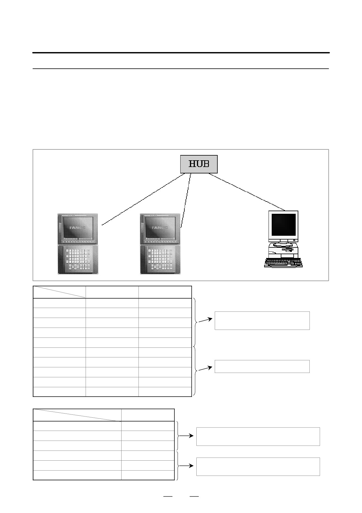
An example of minimum setting required to operate the FACTOLINK
function on a small network is provided below.
Using the FACTOLINK
In this example, one personal computer is connected to two CNCs
function on a small
through FACTOLINK.
network
D On Personal Computer 1, the server of the FACTOLINK function
operates.
D On CNC 1 and CNC 2, the client of the FACTOLINK function
operates.
10BASE-T or 100BASE-TX
CNC 1
CNC 2
PC 1
CNC 1
CNC 2
IP address
192.168.1.1
192.168.1.2
Subnet mask
255.255.255.0
255.255.255.0
The Ethernet parameter screen is used for
Router IP address
None
None
setting.
IP address
192.168.1.100
192.168.1.100
Port number
9000
9000
NC parameter No. 802
21
21
NC parameter No. 820
67 ’C’
67 ’C’
The parameter screen is used for setting.
NC parameter No. 821
78 ’N’
78 ’N’
NC parameter No. 822
67 ’C’
67 ’C’
NC parameter No. 823
49 ’1’
50 ’2’
PC 1
IP address
192.168.0.100
”Microsoft TCP/IP property” of the personal computer
Subnet mask
255.255.255.0
(Windows NT) is used for setting.
Default gateway
None
ocsnc
9000/TCP
Refer to ”FANUC FACTOLINK Script Function OPERA-
ocscomm
9001/TCP
TOR’S MANUAL (B-75054EN)”.
ocsapplication
9002/TCP
613

8. EMBEDDED ETHERNET FUNCTION
B-63525EN/02
8.3.1.5
When configuring a large network or expanding an existing network,
consult with your network manager to set an IP address, subnet mask, and
Configuring a large
router IP address.
network
8.3.2
This subsection describes the settings required to operate the
FOCAS1/Ethernet function (or DNC1/Ethernet function) when the
Parameter Setting of
embedded Ethernet function for the Series 16i/18i/21i/160i/180i/210i/
the FOCAS1/Ethernet
160is/180is/210is-B is used.
Function
8.3.2.1
Notes on using the
FOCAS1/Ethernet
CAUTION
When using the embedded Ethernet function for the first
function for the first time
time, make various settings including IP address setting
carefully and conduct a communication test sufficiently,
consulting with your network manager.
Note that if an incorrect IP address is set, for example, the
entire network can suffer from a communication error.
NOTE
1
The FOCAS1/Ethernet function allows up to five FOCAS1/
Ethernet clients to be connected to one CNC.
2
If multiple application software products or multiple
personal computers access the CNC simultaneously, the
communication load on the CNC can increase, resulting in
decreased communication speed and degraded CNC
screen display processing.
614
B-63525EN/02
8. EMBEDDED ETHERNET FUNCTION
8.3.2.2
On the Ethernet parameter setting screen, set the parameters for operating
the FOCAS1/Ethernet function.
FOCAS1/Ethernet
parameter setting screen
Display
Procedure
1
Place the CNC in the MDI mode.
2
Press the function key
SYSTEM
3
Press the continuous menu key at the right end of the soft key display.
4
Press the [ETHPRM] soft key. The Ethernet parameter setting screen
appears. The Ethernet functions currently available are displayed
The upper row displays the usable embedded Ethernet function
device.
The embedded port or PCMCIA card is displayed.
The lower row displays the usable Ethernet option boards. When no
option board is installed, no information is displayed.
5
By pressing the [EMBEDD] soft key, the parameters for the embedded
Ethernet port can be set.
By pressing the [PCMCIA] soft key, the parameters for the PCMCIA
Ethernet card can be set.
NOTE
The parameters for the embedded Ethernet port and the
parameters for the PCMCIA Ethernet card are independent
of each other.
6
By using the MDI keys and soft keys, enter and update data.
PAGE
7
Switch the screen display with the page keys
PAGE
615
8. EMBEDDED ETHERNET FUNCTION
B-63525EN/02
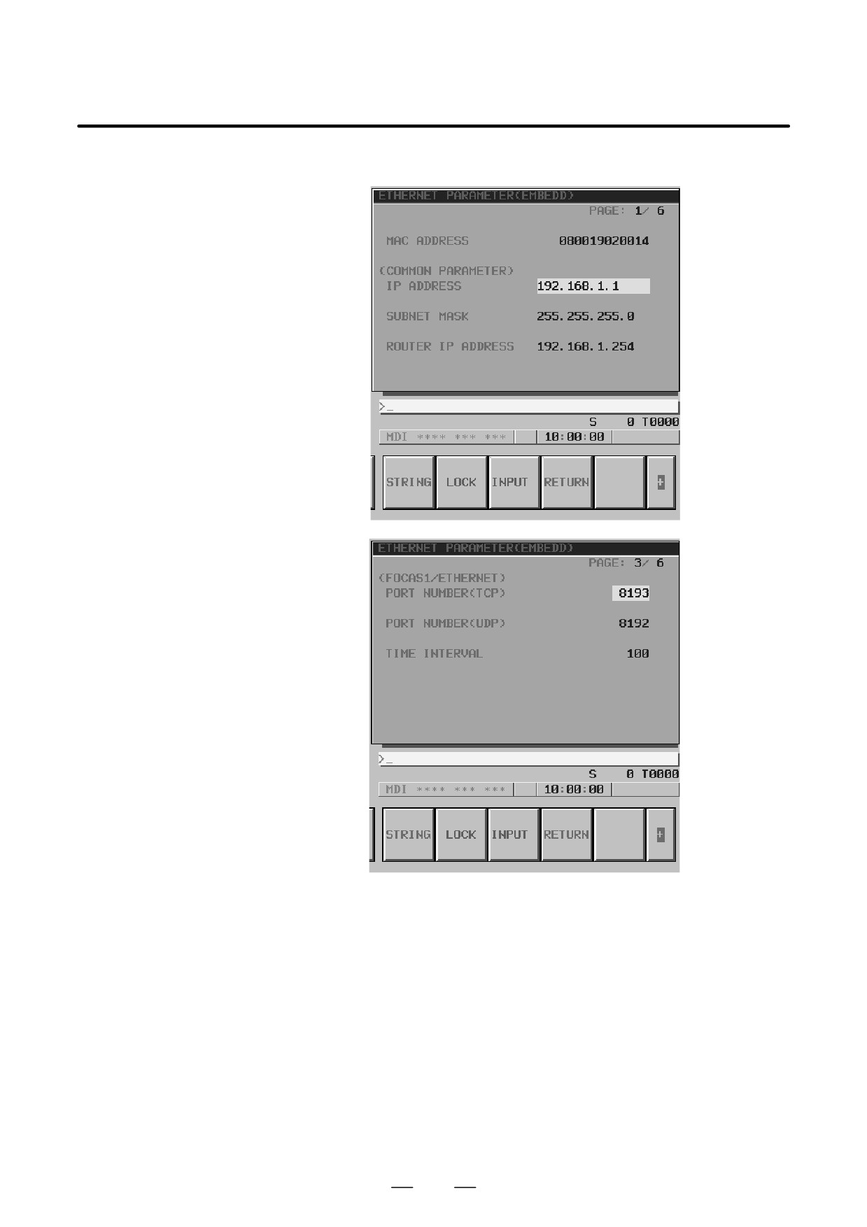
If data is already registered, the data is displayed.
616

B-63525EN/02
8. EMBEDDED ETHERNET FUNCTION
Display item and setting items
Display item related to
The item related to the embedded Ethernet function is displayed.
the embedded Ethernet
Item
Description
function
MAC ADDRESS
Embedded Ethernet MAC address
Embedded Ethernet
Set the TCP/IP-related items of the embedded Ethernet.
TCP/IP setting items
Item
Description
IP ADDRESS
Specify the IP address of the embedded Ethernet.
(Example of specification format: ”192.168.1.1”)
SUBNET MASK
Specify a mask address for the IP addresses of the network.
(Example of specification format: ”255.255.255.0”)
ROUTER IP
Specify the IP address of the router.
ADDRESS
Specify this item when the network contains a router.
(Example of specification format: ”192.168.1.254”)
FOCAS1/Ethernet setting
Set the items related to the FOCAS1/Ethernet function.
items
Item
Description
PORT NUMBER
Specify a port number to be used with the FOCAS1/Ethernet
(TCP)
function. The valid input range is 5001 to 65535.
When using a port number for the DNC1/Ethernet function, refer
to ”FANUC Personal Computer FA System Windows NT Ver-
sion OPERATOR’S MANUAL (B-75044EN)”.
PORT NUMBER
Specify this item when using the DNC1/Ethernet function.
(UDP)
Specify a UDP port number for transmitting UDP broadcast
data.
The valid input range is 5001 to 65535.
For details, refer to ”FANUC Personal Computer FA System
Windows NT Version OPERATOR’S MANUAL (B-75044EN)”.
Set 0 when using the FOCAS1/Ethernet function or when trans-
mitting no UDP broadcast data.
TIME INTERVAL
Specify this item when using the DNC1/Ethernet function.
(NOTE 1)
Specify a time interval at which UDP broadcast data specified
above with a UDP port number is transmitted.
The unit is 10 ms. The valid input range is 10 to 65535. This
means that a value less than 100 ms cannot be specified.
Set 0 when using the FOCAS1/Ethernet function or when trans-
mitting no UDP broadcast data.
Example)
100: Broadcast data is transmitted at intervals of one second
[1000 ms] (= 100
10).
617
8. EMBEDDED ETHERNET FUNCTION
B-63525EN/02
NOTE
1
When a small value is set for the item of time interval,
communication load increases, and the performance of the
network can be adversely affected.
2
The parameters for the PCMCIA Ethernet card are set to the
following default values before shipment:
IP address:
192.168.1.1
Subnet mask:
255.255.255.0
Router IP address:
None
TCP port number:
8193
UDP port number:
0
Time interval:
0
618
B-63525EN/02
8. EMBEDDED ETHERNET FUNCTION
8.3.2.3
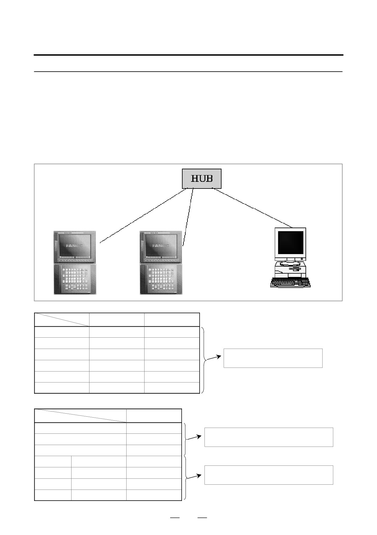
An example of minimum setting required to operate the
FOCAS1/Ethernet function on a small network is provided below.
Using the
In this example, one personal computer is connected to two CNCs
FOCAS1/Ethernet
through FOCAS1/Ethernet.
function on a small
network
D On Personal Computer 1, the client of the FOCAS1/Ethernet function
operates.
D On CNC 1 and CNC 2, the server of the FOCAS1/Ethernet function
operates
10BASE-T or 100BASE-TX
PC 1
CNC 1
CNC 2
CNC 1
CNC 2
IP address
192.168.1.1
192.168.1.2
Subnet mask
255.255.255.0
255.255.255.0
Router IP address
None
None
The Ethernet parameter screen is used for
setting.
TCP port number
8193
8193
UDP port number
0
0
Time interval
0
0
PC 1
IP address
192.168.1.101
”Microsoft TCP/IP property” of the personal computer
Subnet mask
255.255.255.0
(Windows 95/98/NT/2000) is used for setting.
Default gateway
None
CNC 1
NC IP address
192.168.1.1
NC TCP port number
8193
The arguments of the data window library function
cnc_allclibhndl3 are used for setting.
CNC 2
NC IP address
192.168.1.2
NC TCP port number
8193
619
8. EMBEDDED ETHERNET FUNCTION
B-63525EN/02
8.3.2.4
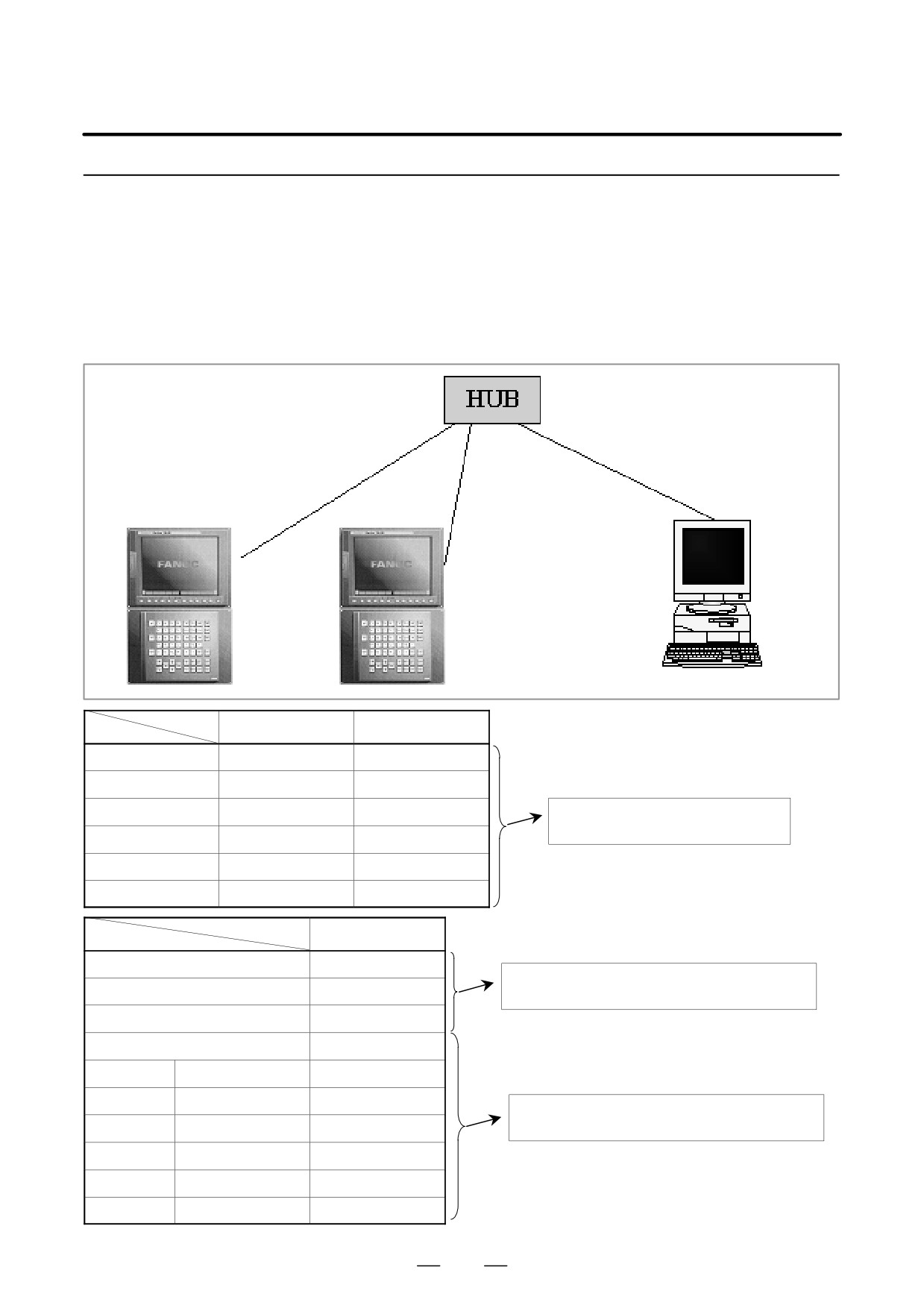
An example of minimum setting required to operate the DNC1/Ethernet
function on a small network is provided below.
Using the DNC1/Ethernet
In this example, one personal computer is connected to two CNCs
function on a small
through DNC1/Ethernet.
network
D On Personal Computer 1, the client of the DNC1/Ethernet function
operates.
D On CNC 1 and CNC 2, the server of the DNC1/Ethernet function
operates.
10BASE-T or 100BASE-TX
PC 1
CNC 1
CNC 2
CNC 1
CNC 2
IP address
192.168.1.1
192.168.1.2
Subnet mask
255.255.255.0
255.255.255.0
Router IP address
None
None
The Ethernet parameter screen is used for
setting.
TCP port number
8193
8193
UDP port number
8192
8192
Time interval
100
100
PC 1
IP address
192.168.1.101
”Microsoft TCP/IP property” of the personal computer
Subnet mask
255.255.255.0
(Windows NT) is used for setting.
Default gateway
None
FANUC_C4_SERVER
8192/udp
CNC 1
Machine No. 1
NC IP address
192.168.1.1
Refer to ”FANUC Personal Computer FA System Win-
dows NT Version OPERATOR’S MANUAL”.
NC TCP port number
8193
CNC 2
Machine No. 2
NC IP address
192.168.1.2
NC TCP port number
8193
620

B-63525EN/02
8. EMBEDDED ETHERNET FUNCTION
8.3.2.5
When configuring a large network or expanding an existing network,
consult with your network manager to set an IP address, subnet mask, and
Configuring a large
router IP address.
network
8.3.3
This subsection describes the settings required to operate the FTP file
transfer function when the embedded Ethernet function for the Series
Parameter Setting of
16i/18i/21i/160i/180i/210i/160is/180is/210is-B is used.
the FTP File Transfer
Function
8.3.3.1
Notes on using the FTP
file transfer function for
CAUTION
When using the embedded Ethernet function for the first
the first time
time, make various settings including IP address setting
carefully and conduct a communication test sufficiently,
consulting with your network manager.
Note that if an incorrect IP address is set, for example, the
entire network can suffer from a communication error.
NOTE
With the FTP file transfer function, only one FTP session
can be established with one CNC.
621
8. EMBEDDED ETHERNET FUNCTION
B-63525EN/02
8.3.3.2
On the Ethernet parameter setting screen, set the parameters for operating
the FTP file transfer function.
FTP file transfer
parameter setting screen
Display
Procedure
1
Place the CNC in the MDI mode.
2
Press the function key
SYSTEM
3
Press the continuous menu key at the right end of the soft key display.
4
Press the [ETHPRM] soft key. The Ethernet parameter setting screen
appears. The Ethernet functions currently available are displayed.
The upper row displays the usable embedded Ethernet function
device.
The embedded port or PCMCIA card is displayed.
The lower row displays the usable Ethernet option boards. When no
option board is installed, no information is displayed.
5
By pressing the [EMBEDD] soft key, the parameters for the embedded
Ethernet port can be set.
By pressing the [PCMCIA] soft key, the parameters for the PCMCIA
Ethernet card can be set.
NOTE
The parameters for the embedded Ethernet port and the
parameters for the PCMCIA Ethernet card are independent
of each other.
6
By using the MDI keys and soft keys, enter and update data.
PAGE
7
Switch the screen display with the page keys
PAGE
622
B-63525EN/02
8. EMBEDDED ETHERNET FUNCTION
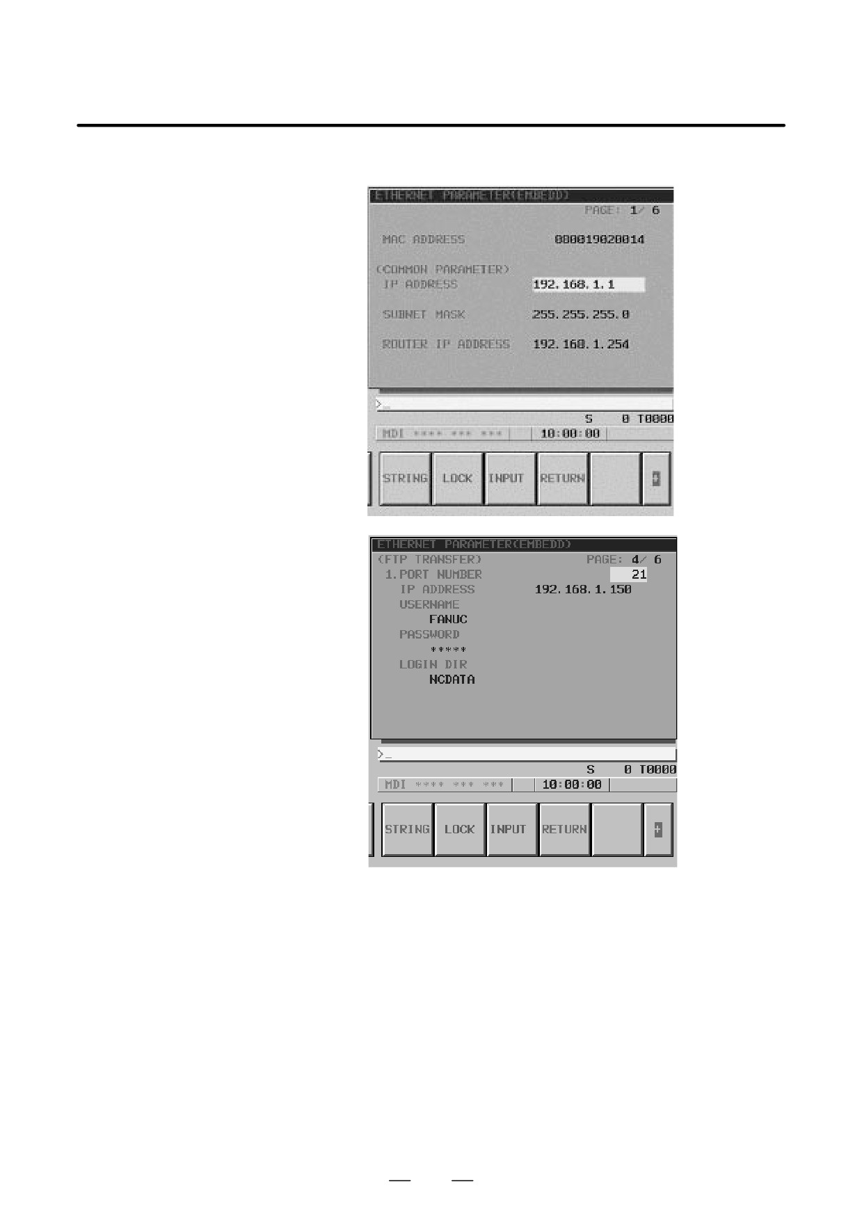
If data is already registered, the data is displayed.
623

8. EMBEDDED ETHERNET FUNCTION
B-63525EN/02
Display item and setting items
Display item related to
The item related to the embedded Ethernet function is displayed.
the embedded Ethernet
Item
Description
function
MAC ADDRESS
Embedded Ethernet MAC address
Embedded Ethernet
Set the TCP/IP-related items of the embedded Ethernet.
TCP/IP setting items
Item
Description
IP ADDRESS
Specify the IP address of the embedded Ethernet.
(Example of specification format: ”192.168.1.1”)
SUBNET MASK
Specify a mask address for the IP addresses of the network.
(Example of specification format: ”255.255.255.0”)
ROUTER IP
Specify the IP address of the router.
ADDRESS
Specify this item when the network contains a router.
(Example of specification format: ”192.168.1.254”)
FTP file transfer setting
Make settings related to the FTP file transfer function.
items
Settings for up to three host computers can be made.
Item
Description
PORT NUMBER
Specify a port number to be used with the FTP file transfer func-
tion.
An FTP session is used, so that ”21” is to be specified usually.
IP ADDRESS
Specify the IP address of the host computer.
(Example of specification format: ”192.168.1.150”)
USERNAME
Specify a user name to be used for logging in to the host com-
puter with FTP.
(Up to 31 characters can be specified.)
PASSWORD
Specify a password for the user name specified above.
Be sure to set a password.
(Up to 31 characters can be specified.)
LOGIN DIR
Specify a work directory to be used when logging in to the host
computer.
(Up to 127 characters can be specified.)
624

B-63525EN/02
8. EMBEDDED ETHERNET FUNCTION
8.3.3.3
The NC parameters related to the FTP file transfer function are described
below.
Parameters
Parameters
0020
I/O CHANNEL: Input/output device selection
[Data type]
Byte
[Valid data range]
9: Select the embedded Ethernet as the input/output device.
0931
Special character (No. 1)
0932
Special character (No. 2)
0933
Special character (No. 3)
0934
Special character (No. 4)
0935
Special character (No. 5)
[Data type]
Byte
[Valid data range]
32 to 126
NC parameters No. 931 to No. 935 enable soft keys to substitute for
characters unavailable with the MDI keys.
When a number other than 0 is set in each of these parameters, [CHAR-1]
to [CHAR-5] are displayed in the input soft keys for special characters.
Example) When 33 is set in parameter No. 931, pressing the [CHAR-1]
soft key enters ”!”.
625
8. EMBEDDED ETHERNET FUNCTION
B-63525EN/02
8.3.3.4
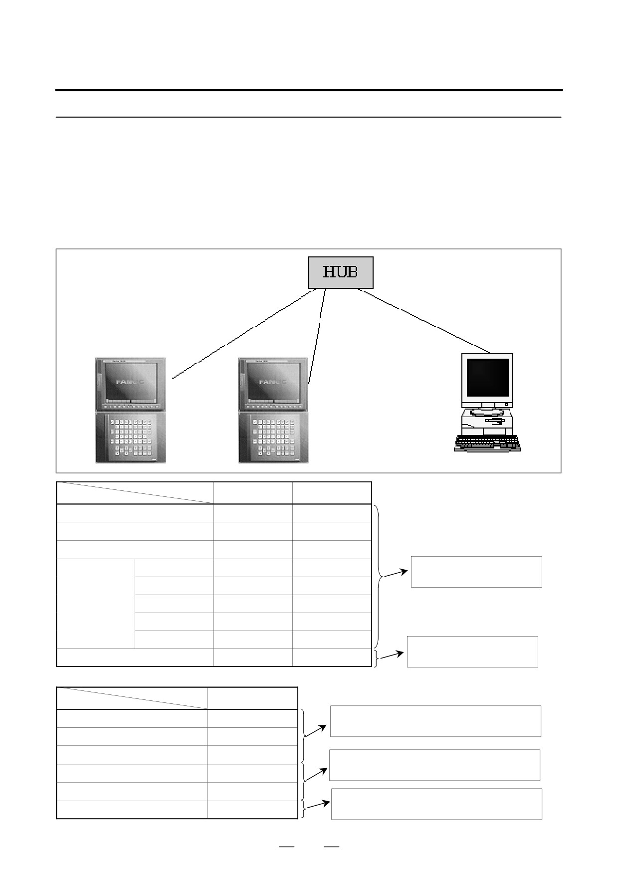
An example of minimum setting required to operate the FTP file transfer
function on a small network is provided below.
(Windows NT 4.0
Using the FTP file
Workstation is used as the OS for the personal computer.)
transfer function on a
In this example, one personal computer is connected to two CNCs
small network
through the FTP file transfer function.
D On Personal Computer 1, the FTP server function operates.
D On CNC 1 and CNC 2, the FTP client operates as the FTP file transfer
function.
10BASE-T or 100BASE-TX
CNC 1
CNC 2
PC 1
CNC 1
CNC 2
IP address
192.168.1.1
192.168.1.2
Subnet mask
255.255.255.0
255.255.255.0
Router IP address
None
None
Connection host 1
Port number
21
21
The Ethernet parameter screen is
used for setting.
IP address
192.168.1.150
192.168.1.150
User name
FANUC
FANUC
Password
FANUC
FANUC
Login DIR
None
None
The parameter screen is used for
NC parameter No. 20
9
9
setting.
PC 1
IP address
192.168.1.150
”Microsoft TCP/IP property” of the personal computer
(Windows NT) is used for setting.
Subnet mask
255.255.255.0
Default gateway
None
”User manager” of the personal computer (Windows
NT) is used for setting.
User name
FANUC
Password
FANUC
”Internet service manager” of the personal computer
Login DIR
Default
(Windows NT) is used for setting.
626
B-63525EN/02
8. EMBEDDED ETHERNET FUNCTION
8.3.3.5
When configuring a large network or expanding an existing network,
consult with your network manager to set an IP address, subnet mask, and
Configuring a large
router IP address.
network
8.3.4
This subsection describes the method of parameter input when the
embedded Ethernet function for the Series 16i/18i/21i/160i/180i/210i/
Communication
160is/180is/210is-B is used.
Parameter Input
Method
Basic method of data input
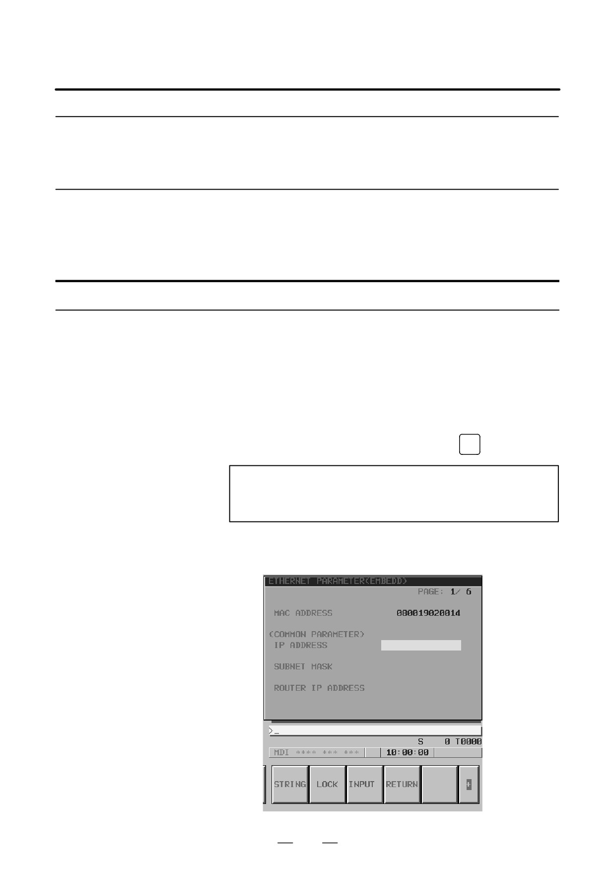
The basic method of data input is described below, using an example of
IP address input.
Procedure
1 Place the CNC in the MDI mode.
2
Display the Ethernet parameter screen.
3
Move the cursor to a desired input item with cursor keys.
4
Type data with MDI keys.
5
Press the [INPUT] soft key or the function key
INPUT
to enter the data.
NOTE
When deleting numeric data already set, enter 0. When
deleting character data already set, enter SP (space).
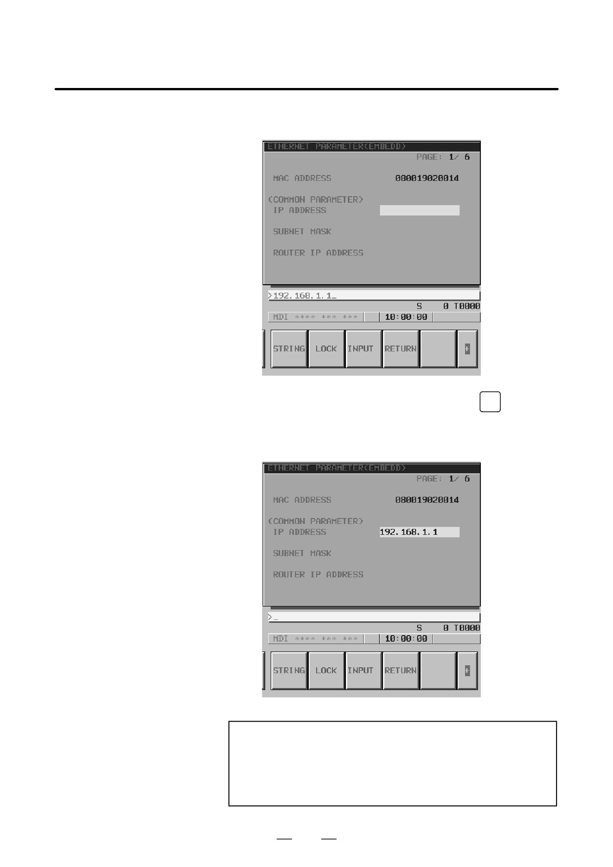
Example) Setting 192.168.1.1 as IP address data
(a) Move the cursor to the item of IP address.
627
8. EMBEDDED ETHERNET FUNCTION
B-63525EN/02
(b) Type 192.168.1.1 with the MDI keys.
(c) Press the [INPUT] soft key or the function key
INPUT
to enter the
data.
This stores the parameter in the nonvolatile memory of the CNC.
NOTE
Turn on the power again so that you should make a changed
parameter effective.
Or, push soft key [RESET] on the maintenance screen of
embedded Ethernet.
628
B-63525EN/02
8. EMBEDDED ETHERNET FUNCTION
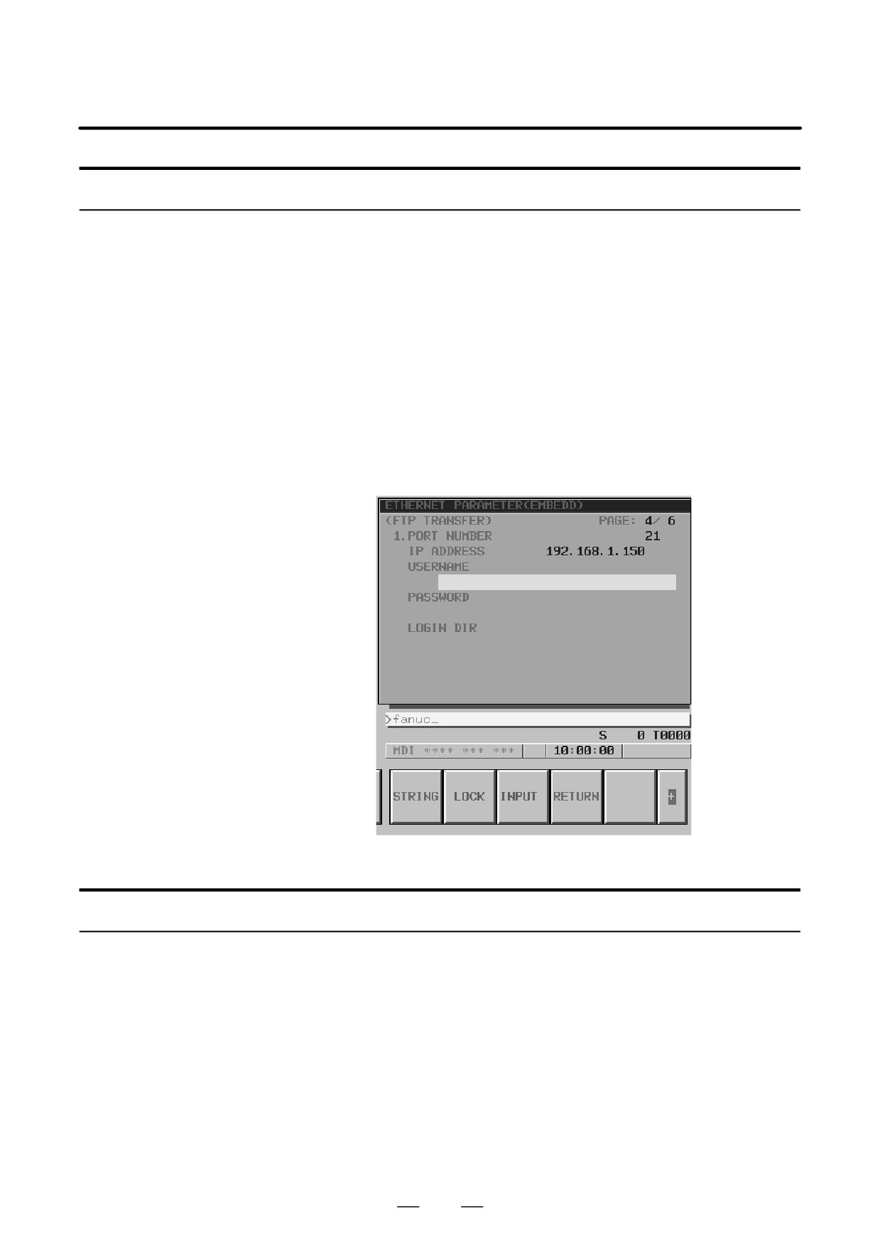
Method of lowercase character input
The method of entering lowercase characters when specifying a user
name, password, and login DIR is described below.
Procedure
1 Place the CNC in the MDI mode.
2
Display the Ethernet parameter screen.
3
Move the cursor to a desired input item with cursor keys.
4
When the [UNLOCK] soft key is displayed, uppercase characters are
actually entered through MDI keys. For lowercase character input,
press the [UNLOCK] soft key. The soft key display changes from
[UNLOCK] to [LOCK].
5
Then, press the MDI keys A through Z. All of these characters are
entered as lowercase characters.
6
To enter uppercase characters, press the [LOCK] soft key.
Method of entering a long character string
The method of entering a character string longer than 32 characters for
specifying a login DIR is described below.
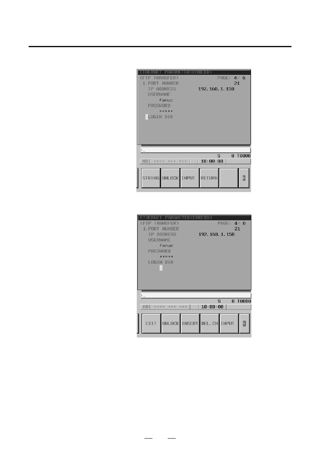
As an example, the processing for setting the character string
”/NCDATA/NCPROGRAM/LINE001/GROUP002” is described.
Procedure
1 Place the CNC in the MDI mode.
2
Display the Ethernet parameter screen.
629
8. EMBEDDED ETHERNET FUNCTION
B-63525EN/02
3
Move the cursor to LOGIN DIR with cursor keys.
4
Press the [STRING] soft key. The cursor position and soft key display
change as shown below.
630
B-63525EN/02
8. EMBEDDED ETHERNET FUNCTION
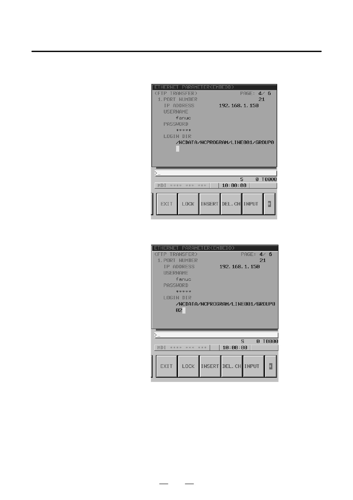
5
Type
”/NCDATA/NCPROGRAM/LINE001/GROUP0” with the
MDI keys, then press the [INPUT] soft key.
6
Next, type the remaining character string ”02” with the MDI keys, then
press the [INPUT] soft key.
[Tip]
For example, even if the character string is divided into
”/NCDATA/NCPROGRAM” and ”/LINE001/GROUP002” for two
input operations the same result can be obtained.
631