FANUC Series 16i/160i/160is-MODEL B, Series 18i/180i/180is-MODEL B, Series 21i/210i/210is-MODEL B. MAINTENANCE MANAUL - page 17
7. INTERFACE BETWEEN CNC AND PMC
B-63525EN/02
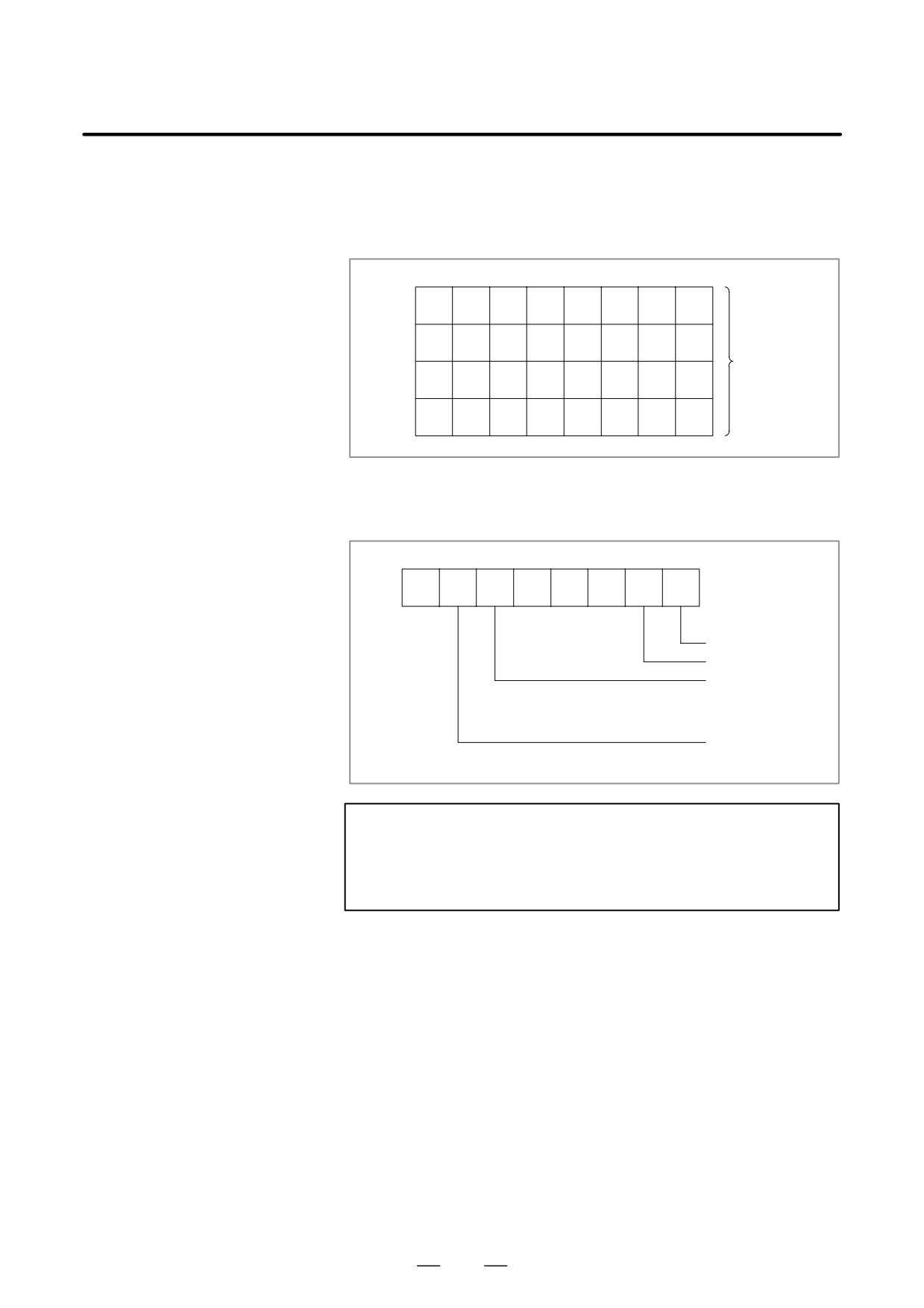
(3) R9002 to R9005 (Operation output registers for the DIVB functional
instruction)
The data remaining after the DIVB functional instruction is executed
in output.
#7
#6
#5
#4
#3
#2
#1
#0
R9002
R9003
Register for
remainder
R9004
(used by DIVB
instruction)
R9005
(4) R9091 (System timer)
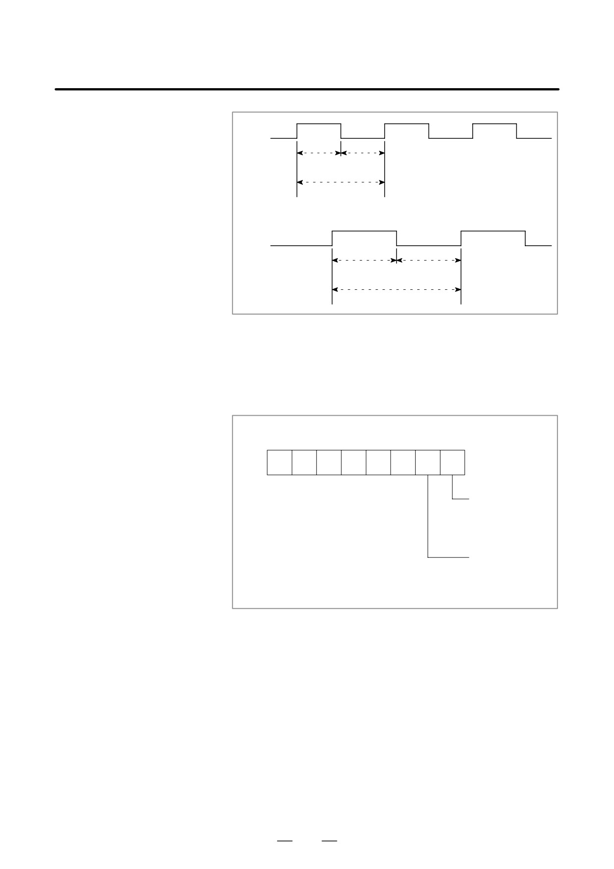
4 signals can be used as system timer.
The specifications of every signal are as following.
#7
#6
#5
#4
#3
#2
#1
#0
R9091
always OFF
always ON
Cyclic signal of 200
ms (104 ms ON, 96
ms OFF)
Cyclic signal of 1 se-
cond. (504 ms ON,
496 ms OFF)
CAUTION
Each signal is initially off. R9091.0 and R9091.1 are set
cyclically at the beginning of the first ladder level.
Each signal (ON-OFF signal) has an accuracy of "8 ms.
452
B-63525EN/02
7.INTERFACE BETWEEN CNC AND PMC
R9091.5
104ms
96ms
200ms
R9091.6
504ms
496ms
1s
(5) Ladder execution start signal, ladder stop signal, ladder execution
state signal (PMC-SB7)
1
Ladder execution start signal and latter stop signal
With the ladder execution start signal or the ladder stop signal, the
start or stop of a ladder program can be known in the ladder
program.
#7
#6
#5
#4
#3
#2
#1
#0
R9015
R9015.0: Ladder
execution start sig-
nal (reference only
from the ladder pro-
gram)
R9015.1: Ladder
execution start sig-
nal (reference only
from the ladder pro-
gram)
2
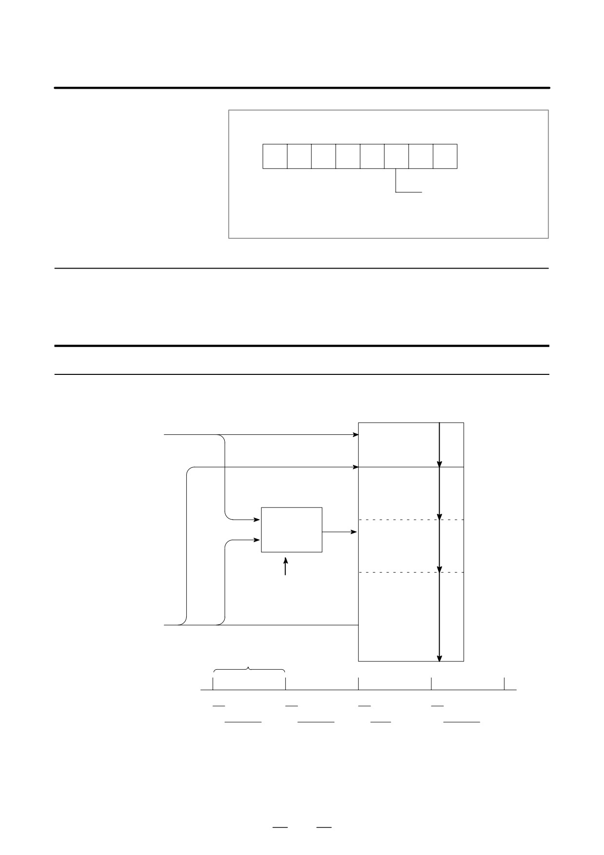
Ladder execution state signal
The state of ladder program execution or PMCC language program
execution can be known by referencing the ladder execution state
signal from an external system or program such as the network
board, C executor program, FOCAS1 Ethernet, and HSSB library.
453
7. INTERFACE BETWEEN CNC AND PMC
B-63525EN/02
#7
#6
#5
#4
#3
#2
#1
#0
R9015
R9091.2: Ladder execution
state signal
0: Ladder stopped
1: Ladder being executed
7.2.4
Execution Period of
PMC
For PMC-SA1
Sequence program
1st level
From NC
(High-speed se-
(1)
quence)
END1
2nd level
(Normal sequence)
(2)-1
Synchronized
buffer
(2)-2
Head of 2nd level
(2)-n
From MT
END2
8msec
Period
(1)
(1)
(1)
(1)
1st level
(2)-1
(2)-2
(2)-n
(2)-1
2nd level
454
B-63525EN/02
7.INTERFACE BETWEEN CNC AND PMC
For PMC-SB7
CNC (F)
1st level
END1
2nd level
Synchronized
buffer
END2
3rd level
END3
Machine (X)
From NC
Ladder execution time
1st level
Division 1
Division 2
Division n
2nd level
3rd level
8ms
8ms
8ms
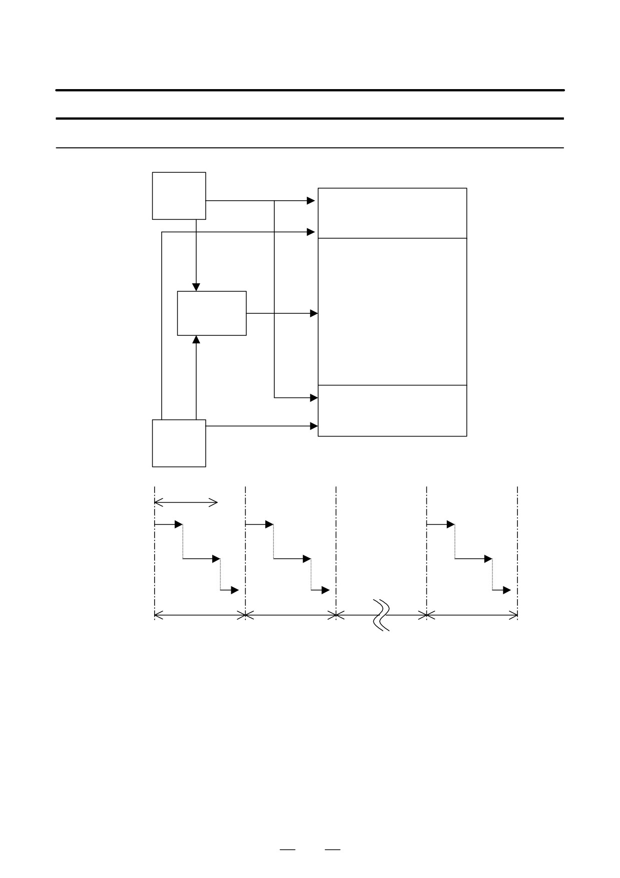
The ratio of the 1st level execution time to the 2nd level execution time
is set in a system parameter for ladder execution time.
D For a ladder that uses the 1st level and the 2nd level only, set the upper
limit (150).
455
7. INTERFACE BETWEEN CNC AND PMC
B-63525EN/02
D For a ladder that uses the 3rd level, the setting of the upper limit (150)
may not ensure full 3rd level operation. In such a case, set this
parameter so that the processing times of the 1st level and 2nd level
are reduced.
The 1st ladder level or the 2nd ladder level processing time is determined
by the following expression:
The 1st ladder level or
Ladder execution time
= 5msec
2nd ladder level processing time
100
The 3rd ladder level processing time is determined by the following
expression:
The 3rd ladder level processing time =
7.5 msec - (1st ladder level
and 2nd ladder level
processing times)
456

B-63525EN/02
7.INTERFACE BETWEEN CNC AND PMC
7.3
PMC SCREEN
7.3.1
PMC Menu Selection
Procedure Using Soft
Keys
PMC-SA1 screen menu selection procedure
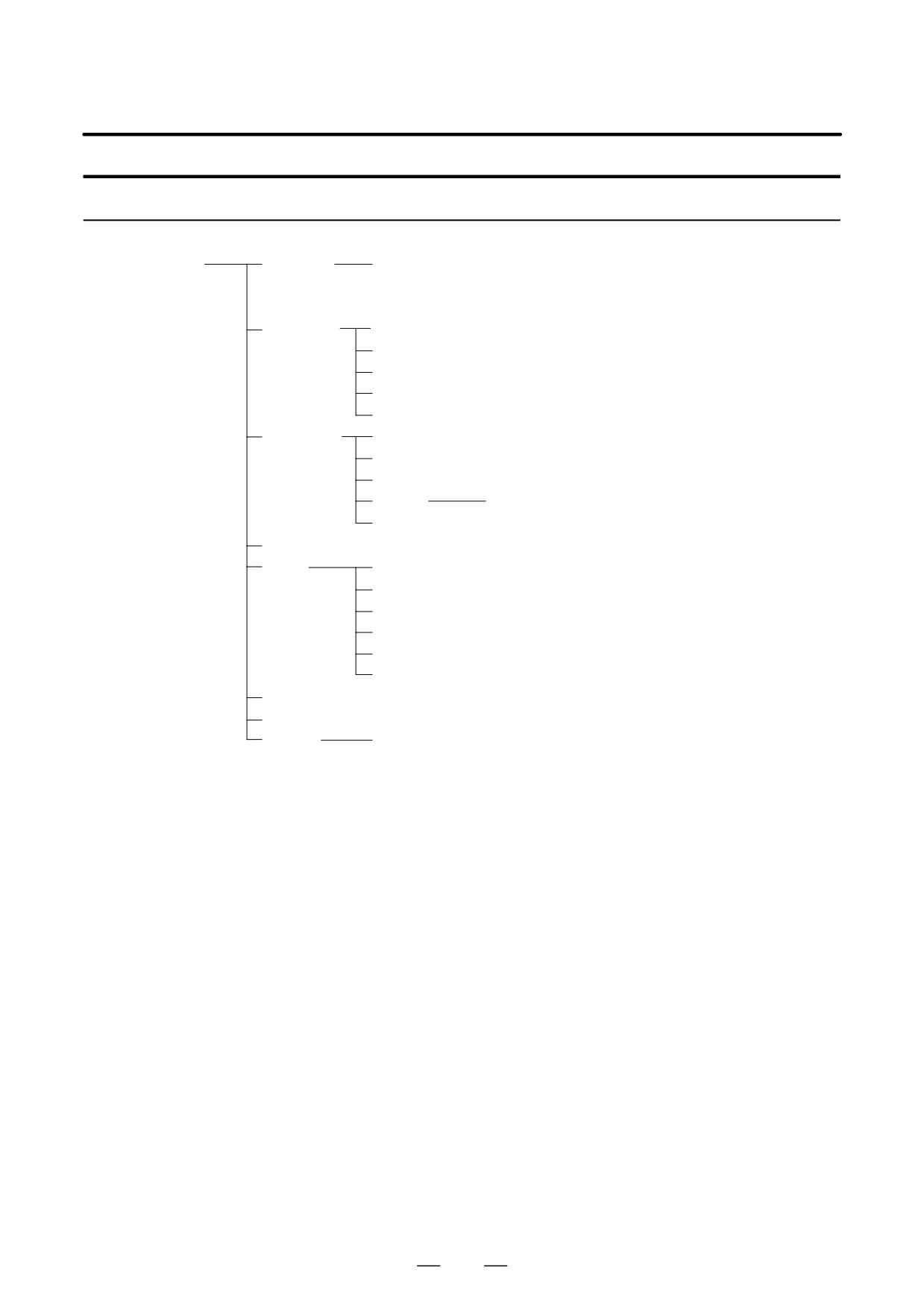
[PMC]
[PMCLAD]
Ladder diagram display screen
[PMCDGN]
[TITLE]
Title screen
[STATUS]
Signal status screen
[ALARM]
Alarm screen
[TRACE]
Trace function
[IOCHK]
I/O check screen
[PMCPRM]
[TIMER]
Timer screen
[COUNTR]
Counter screen
[KEEPRL]
Keep relay screen
[DATA]
[G.DATA]
Data table screen
[SETING]
Setting screen
[RUN]/[STOP]
Ladder start/stop
[EDIT]
[TITLE]
Title editing screen
[LADDER]
Ladder diagram editing screen
[SYMBOL]
Symbol/comment editing screen
[MESAGE]
Message editing screen
[MODULE]
I/O unit address setting screen
[CROSS]
Cross reference screen
[CLEAR]
Clear screen
[I/O]
Program/parameterinput/output screen
[SYSPRM]
System parameter screen
[MONIT]
[ONLINE]
Online setting screen
457
7. INTERFACE BETWEEN CNC AND PMC
B-63525EN/02
PMC-SB7 screen menu selection procedure
[PMC]
[PMCLAD]
[EDIT]
Ladder diagram display screen
Selection monitor function
Ladder diagram editing screen
[PMCDGN]
[TITLE]
Title screen
[STATUS]
Signal status screen
[ALARM]
Alarm screen
[TRACE]
Signal trace screen
[IOCHK]
I/O check screen
[PMCPRM]
[TIMER]
Timer screen
[COUNTR]
Counter screen
[KEEPRL]
Keep relay screen
[DATA]
[G.DATA]
Data table screen
[SETING]
Setting screen
[RUN]/[STOP]
Ladder start/stop
[EDIT]
[TITLE]
Title editing screen
[SYMBOL]
Symbol/comment editing screen
[MESAGE]
Message editing screen
[MODULE]
I/O unit address setting screen
[CROSS]
Cross reference screen
[CLEAR]
Clear screen
[I/O]
Program/parameterinput/output screen
[SYSPRM]
System parameter screen
[MONIT]
[ONLINE]
Online setting screen
458
B-63525EN/02
7.INTERFACE BETWEEN CNC AND PMC
7.3.2
Press soft key
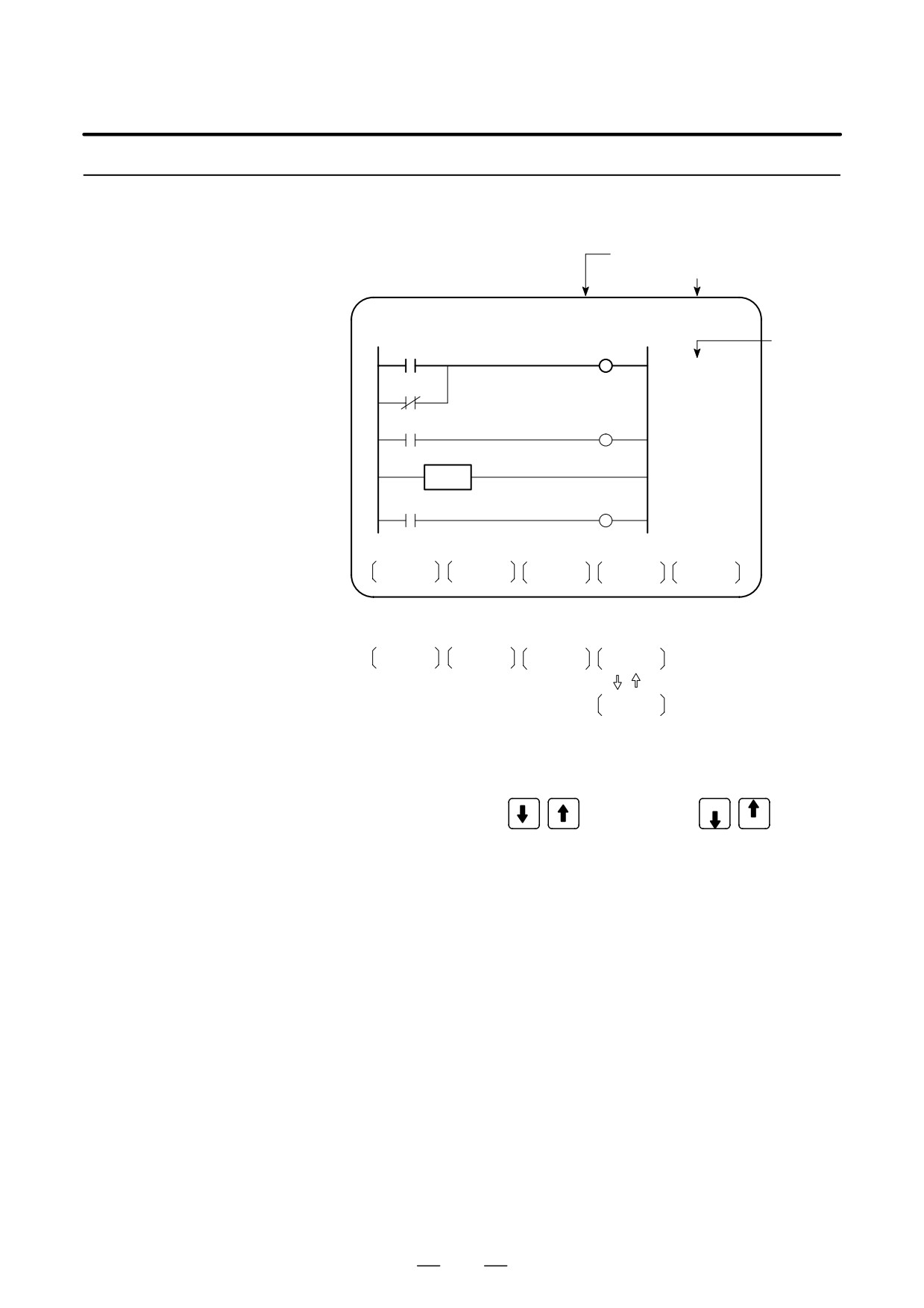
[PMCLAD], and a sequence program is displayed
dynamically and operation monitoring can be confirmed :
PMCLAD Screen
(PMC-SA1)
Number of net displayed
RUN/STOP status
Ladder display
LADDER
NET 0001-0004
MONIT RUN
Comment
LOG1
LOG1
ALWAYS1
LOG1
X008.4
*ESP
EMERGENCY
STOP
END1
PORD
POR
POWER ON
RESET
TOP
BOTTOM
SRCH
W-SRCH
N-SRCH
Other soft keys
F-SCRH
ADRESS
Switched each
time pressed
SYMBOL
D Contents displayed
1. Green (Low brightness) display Contacts :open Relay :off
2. White (High brightness) display Contacts : closed Relay : on
D Search method
1. Use the cursor keys
or the page keys PAGE
to change
PAGE
display positions.
2.
[TOP]:Searches top of ladder.
3.
[BOTTOM]:Search bottom of ladder.
4. Address.bit,[SRCH] or Signal name, [SRCH]
5. Address.bit,[W-SRCH] or Signal name ,[W-SRCH]
6. Net no.[N-SRCH]:Ladder is displayed from the specified net.
7. Functional instruction no.
[F-SRCH] or Functional instruction
name[F-SRCH]
8.
[ADRESS]:Signal is displayed by address and bit no.
9.
[SYMBOL]:Signal is displayed by signal name (symbol).
(If symbol is not registered at program preparation time, the address
of the signal is displayed).
459
7. INTERFACE BETWEEN CNC AND PMC
B-63525EN/02
[Remarks]
⋅
The search function searches a signal in the forward direction and
displays the ladder with the searched signal at its head. Because there
may exist plural contacts, repeat the search operation to find plural
locations, repeat the search operation to find plural locations with the
specified signal.
⋅
If a specified signal is not found up to the end of the program (ladder),
execution returns to the head of a program and search continues.
D Dump display on ladder
Ladder diagram and signal status dump can displayed together.
diagram
The dump is displayed over 2 lines at the last line of ladder diagram by
pressing the [DUMP] soft key.
PAGE
keys or [SEARCH] soft key is used for changing of PMC
PAGE
address.
The [DUMP] soft key has the follwing functions.
(1) [BYTE]: Byte type display (1 BYTE)
“G0000 00 14 00 00 01 00 00 00 00 00 00 00 00 00 00 00”
“G0016 00 00 00 00 00 00 00 00 00 00 00 00 00 00 00 00”
(2) [WORD] : Word type display (2 BYTE)
“G0000 1400 0000 0001 0000 0000 0000 0000 0000”
“G0016 0000 0000 0000 0000 0000 0000 0000 0000”
(3) [D.WORD]: Long word type display (4 BYTE)
“G0000 00001400 00000001 00000000 00000000”
“G0016 00000000 00000000 00000000 00000000”
D Parameter display on
The value of parameter of a functional instruction is displayed in the
ladder diagram
functional instruction of a ladder diagram.
The function of the soft key is as follows:
(1) [DPARA]
: The value of parameter is displayed in functional
instruction.
(2) [NDPARA]
: The value of parameter is not displayed in functional
instruction.
D Stop of ladder diagram
The ladder display can be stopped by manual operation or trigger of
display by trigger of
signal.
signal
The former ladder diagram display renews signal status every moment.
But by using this function, all the ladder diagram at the specified moment
can be checked.
The stop conditions as a trigger are specified by rising or falling edge
detection of the designated signal.
460
B-63525EN/02
7.INTERFACE BETWEEN CNC AND PMC
The setting address, condition and counter are displayed at the title line.
D Display of setting trigger
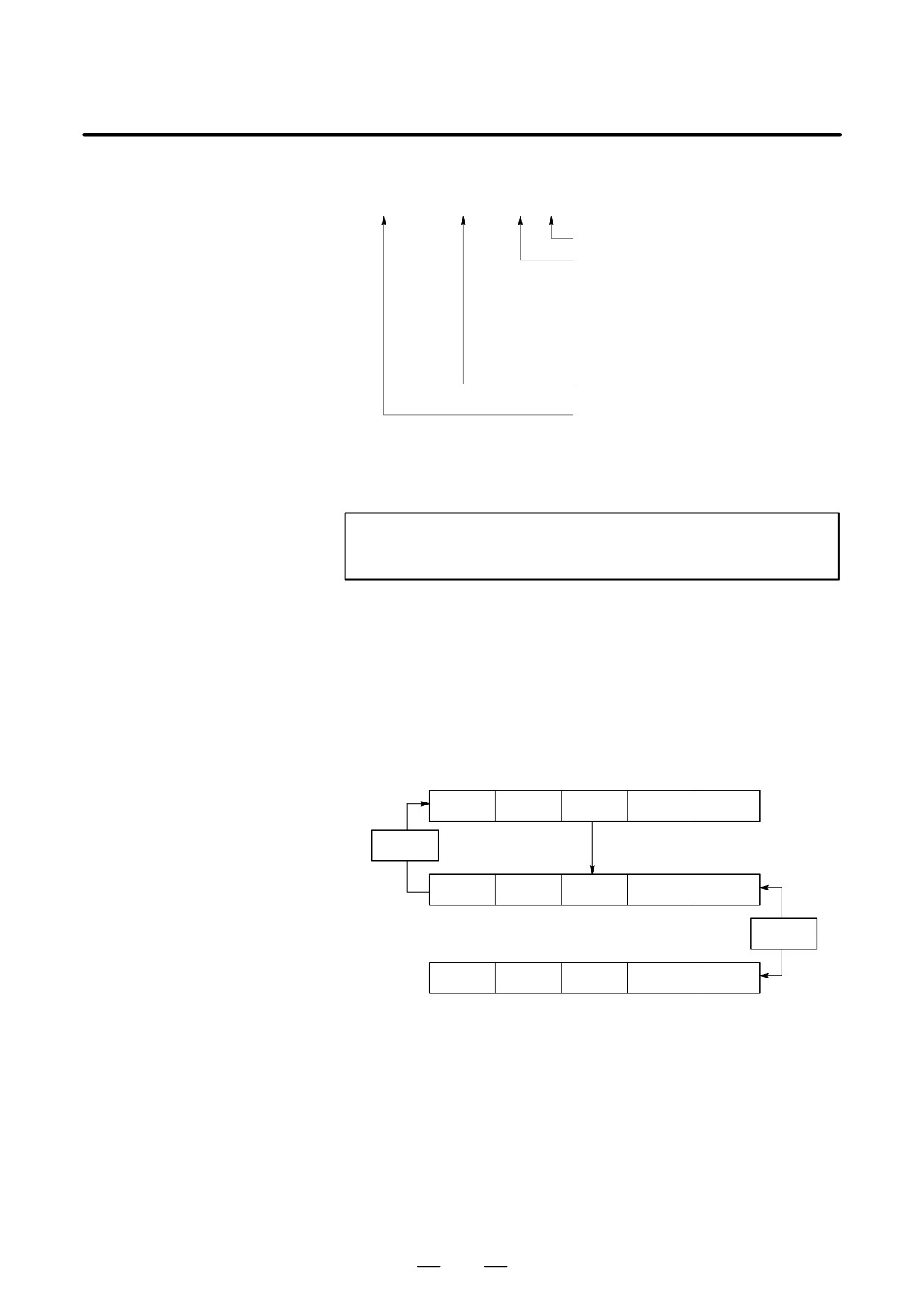
“MODE:ON : X0000. 0 : 0 : 0001 ”
COUNT: Trigger checking number (default 1)
POINT: Trigger checking number (default 0)
0 : the top of the 1st level
1 : after END1 execution
2 : after END2 execution
3 : after END3 execution
ADR: Trigger setting address
ON: Rising edge detection (TRGON)
OFF: Falling edge detection (TRGOFF)
* Setting form adr ;p1 ;p2+[TRGON/TRGOFF]soft key
NOTE
“;”=“EOB”
Adr (trigger address) ;p1 (trigger point) ;p2 (trigger checking number
(1 to 65535))
* Because parameters are stored in the nonvolatile memory, they are not
lost even if the power is turned off.
When bit 2 of keep relay K18 is set to 1 after parameters for sampling
are specified, the trigger function automatically starts when the power
is turned on.
For this operation, depress [TRIGER] soft key to bring the following
menu.
SEARCH
ADRESS
TRIGER
WINDOW
RET
TRGON
TRGOFF
START
NEXT
DUMP
DPARA
TRGSRC
INIT
The function of the [TRIGER] soft key is explained below:
(1) [TRGON] : The trigger function is stopped when a specified address
signal goes high (is turned ON).
(2) [TRGOFF] : The trigger function is stopped when a specified address
signal goes low (is turned OFF).
(3) [START]
: Pressing this key switches between trigger function
execution and trigger function termination. While the
trigger function is being executed, the “TRG” indication
blinks.
461
7. INTERFACE BETWEEN CNC AND PMC
B-63525EN/02
(4) [TRGSRC] : An instruction at which the trigger function has been
stopped by a specified address signal is searched for and
indicated by blinking.
(5) [INIT]
: The trigger setting is initialized.
D Divided display of ladder
This function is used for displaying the divided screen. It can display
diagram
max. six division.
For this operation, depress [WINDOW] soft key to bring the following
menu.
SEARCH
ADRESS
TRIGER
WINDOW
RET
DIVIDE
CANCEL
DELETE
SELECT
WIDTH
The function of the soft key [WINDOW] is as follows:
(1) [DIVIDE]
: The screen will be divided.
The dividing display of ladder diagram can be
displayed for the designated NET number.
(NET number+[DIVIDE])
(2) [CANCEL]
: The dividing display of ladder diagram display ends.
(The screen returns to normal display.)
(3) [DELETE]
: The screen division subject to operation is ended.
(4) [SELECT]
: Change the screen subject to division operation.
The screen in operation is displayed by “purple” title
line, another screen is displayed by “blue” title line.
In monochrome, the screen is displayed by changing
brightness.
(5) [WIDTH]
: Change the width of division by using [EXPAND] or
[SHRINK] soft key.
(6) [EXPAND]
: The divided screen is expanded.
(7) [SHRINK]
: The divided screen is shrank.
D ON-LINE EDIT
When bit 1 in the keep relay K17 is 1, this function is available and
[ONLEDT] soft key is displayed.
When the ladder program is executing, a part of the ladder program can
be changed.
S Change the type of contact (A contact, B contact)
S Change address of contact and coil.
S Change address parameter of functional instruction.
This function don’t change the size.
(Cannot be Addition, deletion and chanegable data size)
When bit 3 in the keep relay K18 is 1, this program is automatically
transferred to backup RAM after on-line edit.
When bit 3 in the keep relay K18 is 0, transfer to backup RAM with COPY
function of I/O screen. If power is off without this operation, edited data
is lost.
462
B-63525EN/02
7.INTERFACE BETWEEN CNC AND PMC
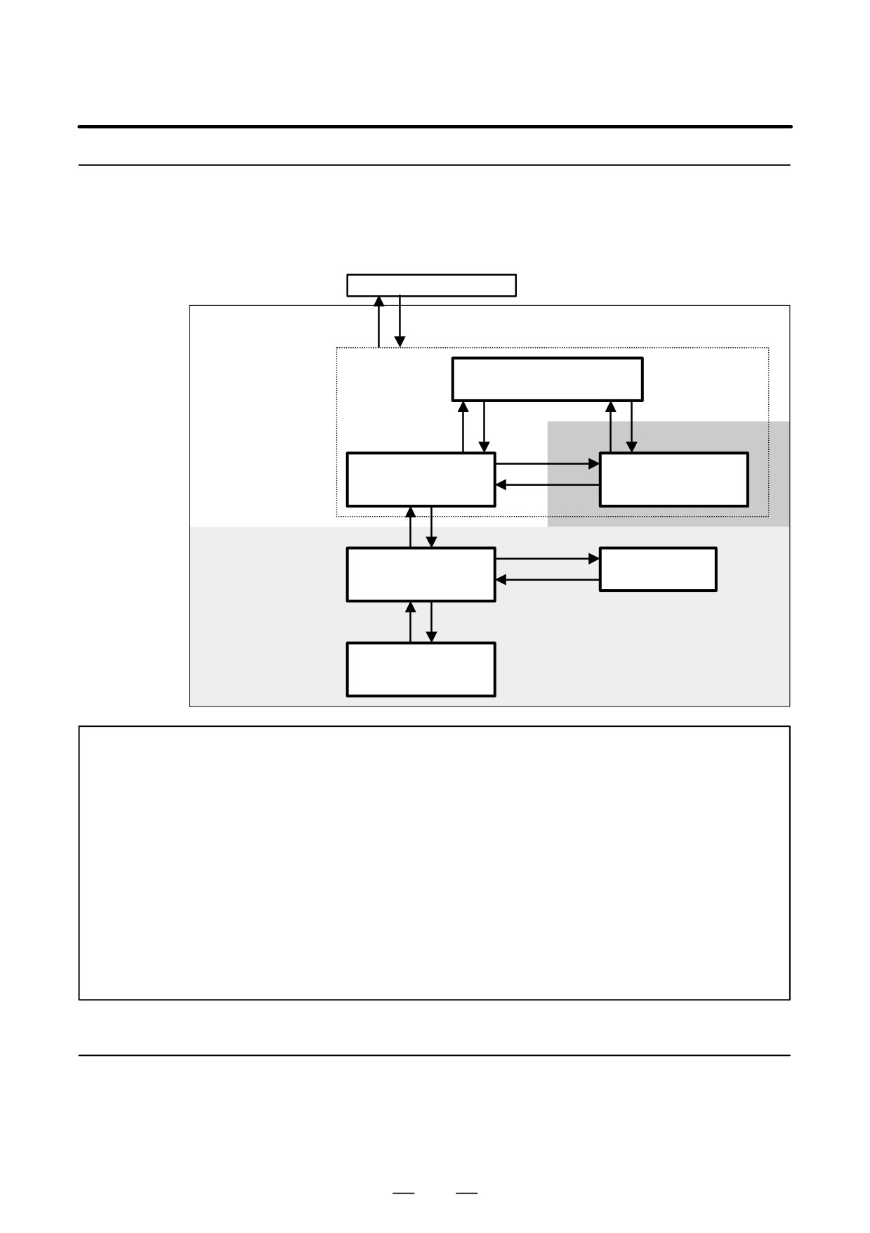
7.3.3
Screen transitions are made as shown below.
Ladder Diagram
Display/Editing
(PMC-SB7)
PMC main menu
[<]
[LADDER DIAGRAM]
Display
(NOTE 1)
Display function
Program list
(monitor)
display screen
[LIST]
[ZOOM]
[LIST]
[ZOOM]
[SWITCH]
Ladder diagram
Selectionmonitor
display screen
screen
[SWITCH]
[EDIT]
[<]
[LIST]
Program list
Ladder diagram
Editing function
editing screen
editing screen
[ZOOM], [<]
[<]
[MODIFY], [ADD]
Net editing screen
NOTE
1. When you press the [LADDER DIAGRAM] soft key, the screen previously displayed among the
ladder diagram display screen, selection monitor screen, and program list display screen is
displayed. However, when you press the [LADDER DIAGRAM] soft key for the first time after
turning on the power, the program list display screen is displayed. If a ladder program is
replaced by using the input/output function, the program list display screen is first displayed.
For details, see the description of the program list display screen.
2. The [EDIT] soft key on the ladder diagram display screen is displayed only when the
programmer function is enabled.
(To enable the programmer function, specify “YES” for the
setting item “Enable Programmer Function” on the PMC parameter setting screen, or set
K900.1 to 1.) Alternatively, specify “YES” for “Enable Editing” or set K901.6 to 1. While the
online monitor function is enabled, the screen display cannot be switched to the ladder diagram
editing screen.
(To disable the online monitor function, set “Not Used” for “RS-232C” and
“High-speed Interface” on the online monitor setting screen.
7.3.3.1
Ladder diagram display
D Display subprogram switching
[LIST]
screen
D Search for addresses
[SEARCH]
D Function instruction data table display
[TABLE]
463
7. INTERFACE BETWEEN CNC AND PMC
B-63525EN/02
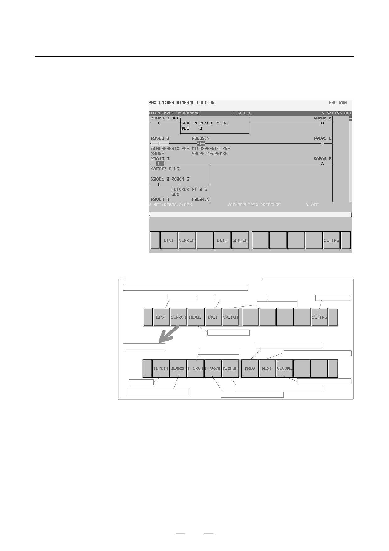
D Transition to the selection monitor screen
[SWITCH]
D Forced input/output function (FORCING mode)
“Number” + ENTER key
Screen manipulation
Soft keys on the ladder diagram display screen
Main soft keys on the ladder diagram display screen
Program list
Ladder diagram editing
Screen setting
Selection monitor
Data table display
Search soft key
Re-search in forward direction
Right coil search
Re-search in reverse direction
Start/end
Search range switching
Reading into the selection monitor screen
Address/net number search
Function instruction search
(a) Manipulation using soft keys
1
[LIST] Calling the program list display screen
This soft key calls the program list display screen. The program
list display screen enables you to select a subprogram to be
displayed on the ladder diagram display screen.
2
[SEARCH] Search/jump menu
This soft key displays the soft keys for search. To return to the main
soft key display, use the return key [<].
The soft keys for search are described below.
D [TOPBTM] Start/end
This soft key makes a jump to the start of the ladder program.
If the start of the ladder program is already displayed, a jump
is made to the end of the ladder program.
464
B-63525EN/02
7.INTERFACE BETWEEN CNC AND PMC
D
[SEARCH] Address/net number search
This soft key searches for the address or net number
corresponding to an entered character string, and displays the
address on the screen. Both a bit address and a byte address can
be searched for.
When a number is entered, it is assumed to be a net number, and
a jump is made.
When a character string other than numbers is entered, a check
is made to see if the character string is defined as a symbol. If
the character string is defined as a symbol, the address
represented by the symbol is searched for.
If the character string is not defined as a symbol, the character
string is interpreted as a character string representing an
address. If interpretation is performed normally, the address is
searched for.
If an address is searched for without displaying the cursor, the
screen display is moved so that the net including a found relay
is placed at the top of the screen. If an address is searched for
with the cursor displayed, the cursor directly moves to the found
relay.
D
[W-SRCH] Right coil search
This soft key searches for the bit address represented by an
entered character string. A search is made only when the
address is used for a right coil. Even if the bit address is used
for an ordinary contact, the address is not searched for.
D
[F-SRCH] Function instruction search
This soft key searches for a function instruction when a function
instruction number or function instruction name is entered.
D
[PICKUP] Reading of a ladder net into the selection monitor
screen
This soft key reads a ladder net to be monitored into the
selection monitor screen.
D
[PREV] Previous candidate
This soft key repeats the previously successful search operation
towards the start.
D
[NEXT] Next candidate
This soft key repeats the previously successful search operation
towards the end.
D
[GLOBAL]/[LOCAL] Range switching
This soft key switches the search target between the whole
ladder program (whole) and subprogram currently displayed
(local). This soft key is displayed only when a subprogram is
displayed. The current search range is displayed at the right end
of the information display line at the top of the screen.
3
[TABLE] Calling the function instruction data table display screen
This soft key displays the data table of a function instruction with
a data table such as the COD instruction (SUB7) or CODB
instruction (SUB27). This soft key is displayed only when the
cursor is placed on a function instruction with a data table.
465
7. INTERFACE BETWEEN CNC AND PMC
B-63525EN/02
4
[EDIT] Calling the ladder diagram editing screen
This soft key switches the screen display to the ladder diagram
editing screen. This soft key is displayed only when the
programmer function is enabled. While the online monitor
function is enabled, the screen display can be switched to the ladder
diagram editing screen. If a password is set for the ladder program,
the input of the password is requested. Enter the password required
for editing.
5
[SWITCH] Calling the selection monitor screen
This soft key displays the selection monitor screen.
6
[SETING] Screen setting
This soft key calls the setting screen for the ladder diagram display
screen. Various settings for ladder diagram display can be
modified. To return to the ladder diagram display screen, use the
return key [<]. For details of the setting screen, see “Screen setting”
in the description of the ladder diagram display screen.
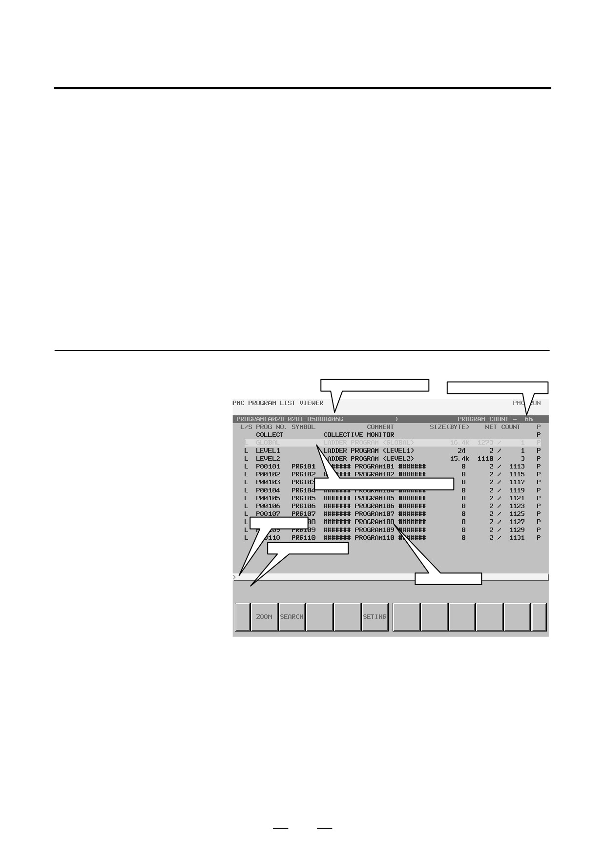
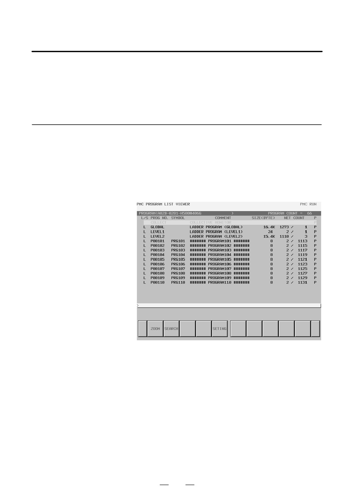
7.3.3.2
Program list display
Title information (details)
Total number of programs
screen
Program subject to manipulation
Key input line
Message display line
List display area
Detail display screen
466
B-63525EN/02
7.INTERFACE BETWEEN CNC AND PMC
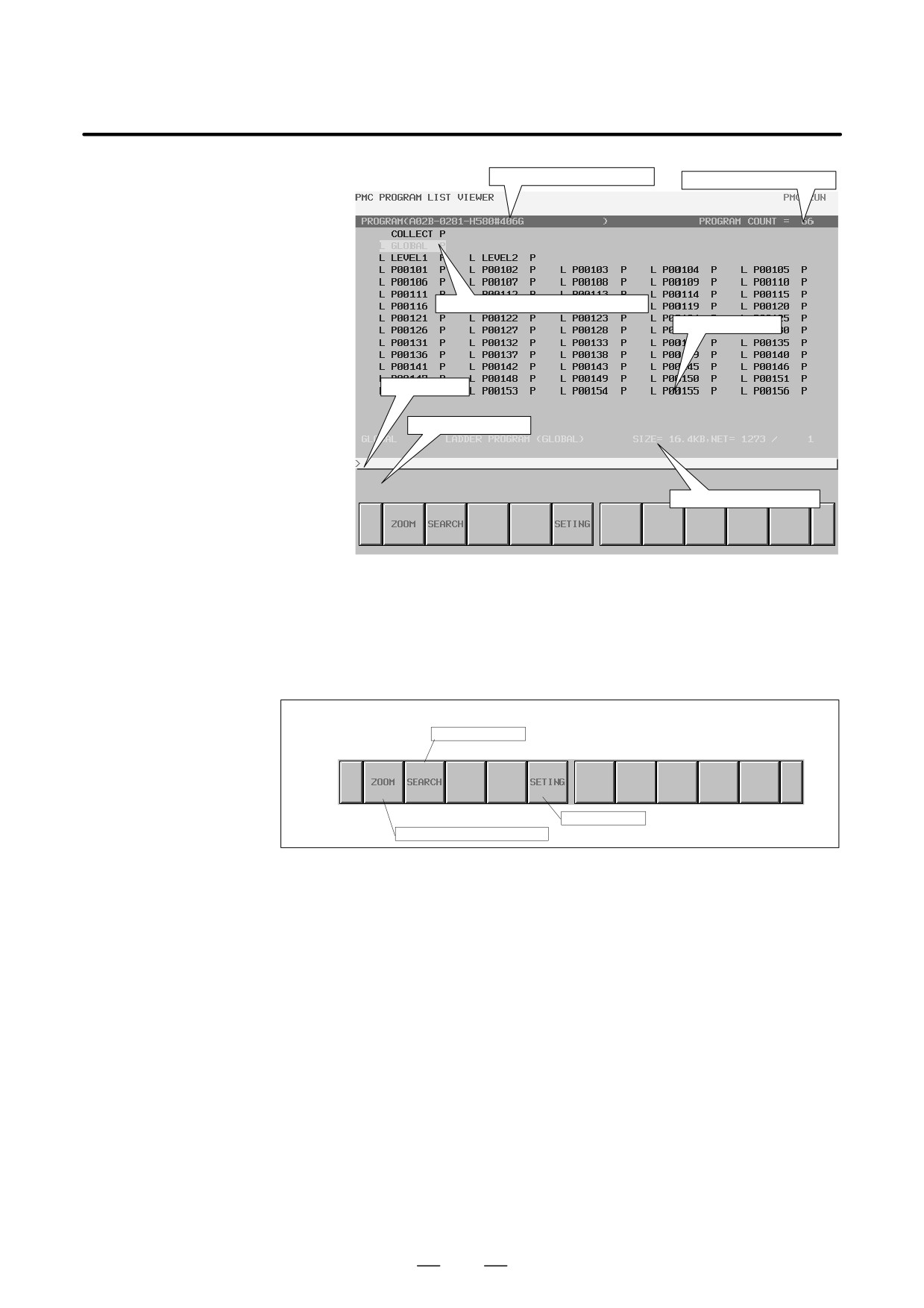
Title information (details)
Total number of programs
Program subject to manipulation
List display area
Key input line
Message display line
Additional information line
Simplified display screen
A choice between the detail display screen and simplified display screen
can be made on the setting screen.
Screen manipulation
Soft keys on the program list screen
Program search
Screen setting
Display of program contents
(a) Manipulation using soft keys
1
[ZOOM] Display of program contents
This soft key switches the screen display to the ladder diagram
display screen. When you press the [ZOOM] soft key without
entering any character string, the program on which the cursor is
placed is displayed on the ladder diagram display screen. When
you press the [ZOOM] soft key after entering a program name
(reference: (c)<1>) or symbol name, the program corresponding to
the entered character string is searched for and displayed on the
ladder diagram display screen.
If the target program is protected so that it cannot be referenced, the
password needs to be released.
2
[SEARCH] Program search
This soft key searches for a program. When you press the
[SEARCH] soft key after entering a program name (reference:
(c)<1>) or symbol name, the program corresponding to the entered
character string is searched for, and the cursor moves to the
program.
467
7. INTERFACE BETWEEN CNC AND PMC
B-63525EN/02
3
[SETING] Screen setting
This soft key calls the setting screen for the program list display
screen. Various settings for program list display can be modified.
To return to the program list display screen, use the return key [<].
For details of the setting screen, see
“Screen setting” in the
description of the program list display screen.
7.3.3.3
On the selection monitor screen, only a ladder net including a coil to be
monitored can be specified for ladder net monitoring.
Selection monitor
function (PMC-SB7)
Calling the screen
The selection monitor screen can be called as described below.
1
Calling the screen from the program list display screen
On the program list screen, move the cursor to the “COLLECT”
program position, then press the [ZOOM] soft key.
Program list display screen
468
B-63525EN/02
7.INTERFACE BETWEEN CNC AND PMC
2
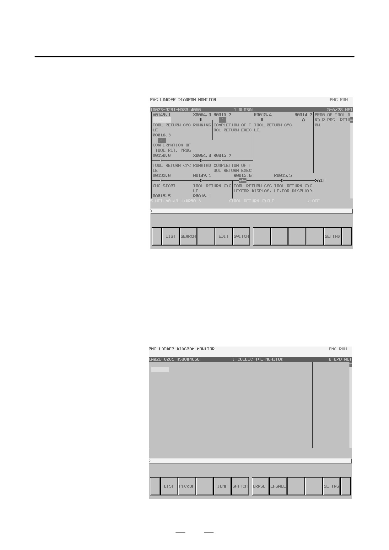
Calling the screen from the ladder diagram display screen
On the ladder diagram display screen, press the [SWITCH] soft key.
Ladder diagram display screen
Selection monitor screen
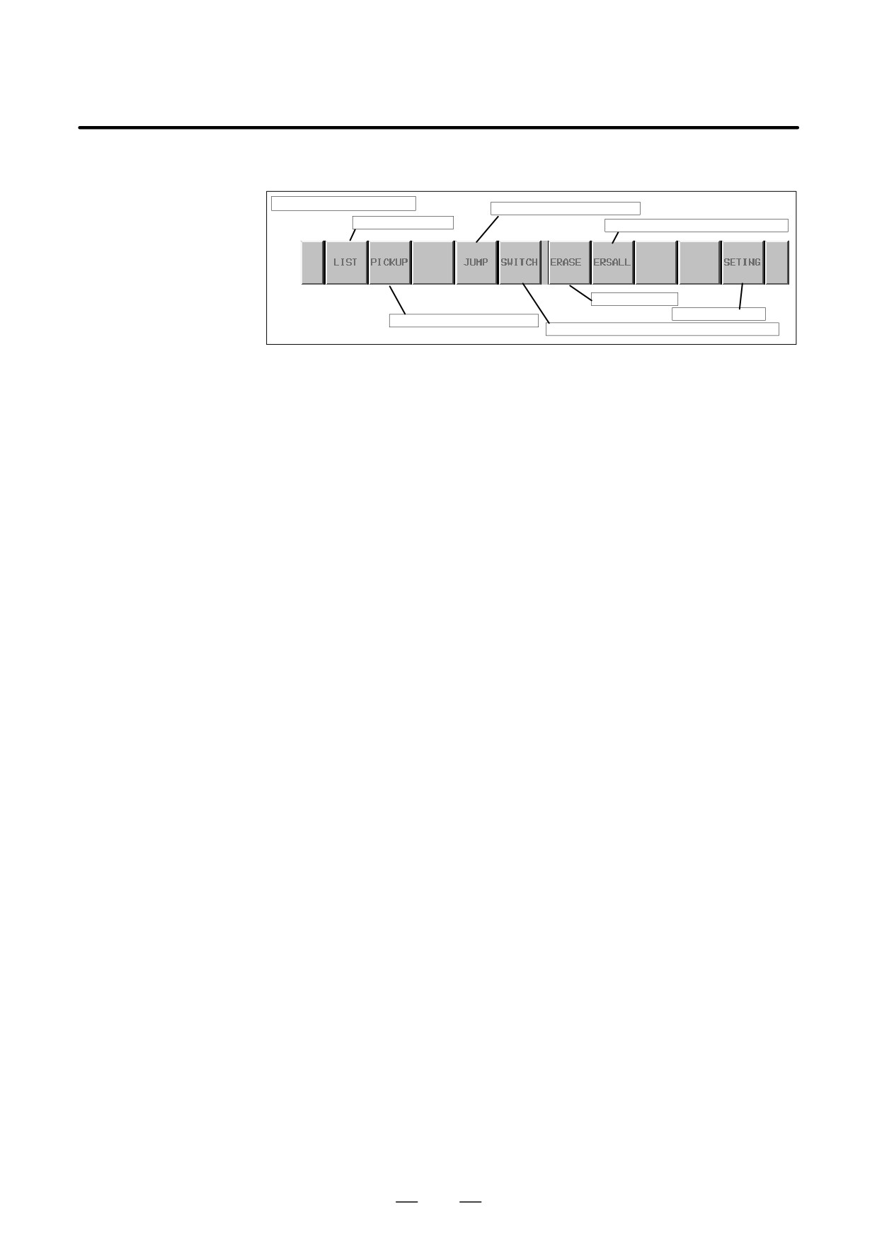
The selection monitor screen is shown below. Initially, no ladder diagram
is displayed. Ladder nets selected by coil search and read operation are
added step by step. Finally, up to 128 nets can be added on the selection
monitor screen. If more than 128 nets are added, the latest 128 nets added
are displayed.
Selection monitor screen (initial screen)
469
7. INTERFACE BETWEEN CNC AND PMC
B-63525EN/02
Screen manipulation
Selection monitor screen
Jump to a ladder diagram net
Program list screen
Selection monitor screen initialization
Erasing one net
Setting for display
Reading a ladder diagram net
Switching to the ladder diagram display screen
Soft keys on the selection monitor screen
(a) Manipulation using soft keys
1
[LIST] Calling the program list display screen
This soft key calls the program list display screen. The program
list display screen enables you to select a subprogram to be
displayed on the ladder diagram display screen.
2
[PICKUP] Reading a ladder net
With this soft key, a ladder net including a coil to be monitored can
be read into the selection monitor screen.
3
[JUMP] Jump to a ladder net
This soft key searches the ladder diagram display screen for the
ladder net where the cursor is placed on the selection monitor
screen, and makes a jump to the net.
4
[SWITCH] Switching to the ladder diagram display screen
This soft key switches the screen display to the ladder diagram
display screen.
5
[ERASE] Erasure of ladder diagram net display (one net)
This soft key erases the display of one ladder net read into the
selection monitor screen.
6
[ERSALL] Erasure of ladder diagram net display (all nets)
This soft key erases the display of all ladder nets read into the
selection monitor screen.
7
[SETING] Screen setting
This soft key calls the setting screen for the selection monitor
screen. Various settings for ladder diagram display can be
modified. To return to the selection monitor screen, use the return
key [<].
D Specifying a ladder
The methods described below are available to read a ladder net to be
diagram to be monitored
monitored on the selection monitor screen.
1
Specifying a ladder net on the selection monitor screen
D Specification of an address
Key in the address used for a coil to read the net.
D Specification of a ladder net on the selection monitor screen
Specify a relay on an already read ladder net with the cursor, and
read the net where the relay address is used for a coil.
2
Specifying a ladder net on the ladder diagram display screen
Specify a net on the ladder diagram display screen to read the net
into the selection monitor screen.
470
B-63525EN/02
7.INTERFACE BETWEEN CNC AND PMC
D Reading a ladder net on
A ladder net can be read from the selection monitor screen. Use the
the selection monitor
procedure below to read a ladder net.
screen
(a) Specification of an address
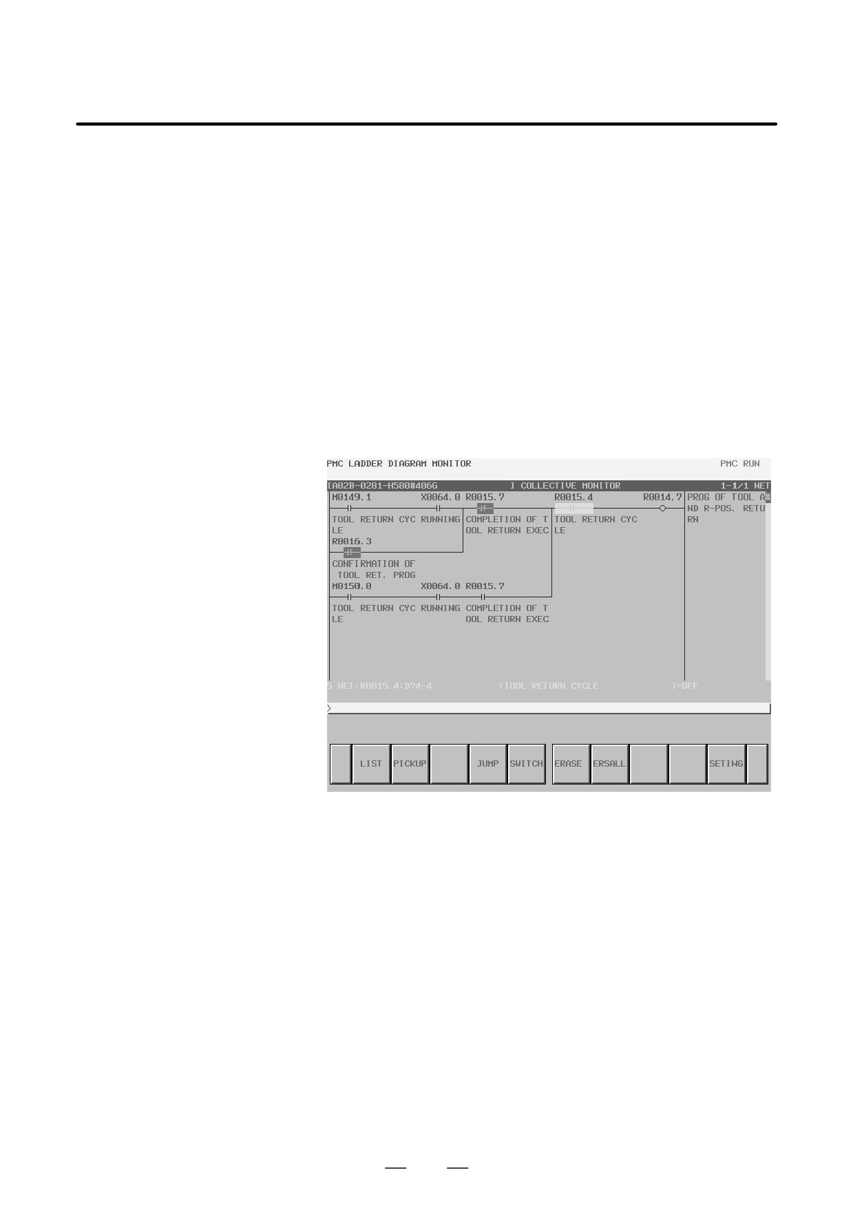
1
Enter an address to be monitored. (Example: R14.7)
2
Press the [PICKUP] soft key.
3
The net where the address specified in 1 above is used for a coil
is read into the start of the screen.
(b) Specification of an address from the ladder net on the screen
1
Move the cursor to the relay, in a ladder net, which uses an
address to be monitored.
2
Press the [PICKUP] soft key.
3
The net where the address specified in 1 above is used for a coil
is read into the start of the screen, and the cursor moves to the
coil position.
Selection monitor screen
D Reading a ladder net
A ladder net can be read from the ladder diagram display screen. Use the
from the ladder diagram
procedure below to read a ladder net.
display screen
1
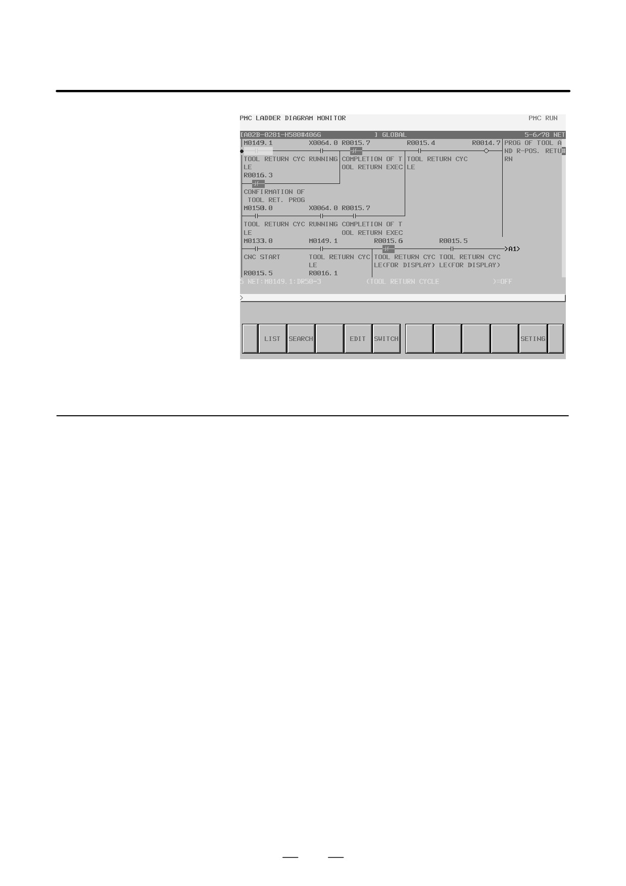
On the ladder diagram display screen, press the [SEARCH] soft
key to display the soft keys for search.
2
Move the cursor to a ladder net to be read.
3
Press the [PICKUP] soft key to read the net specified in 2 above to
the start of the selection monitor screen.
4
The ladder net read into the selection monitor screen is marked with
F at the left end of the net.
471
7. INTERFACE BETWEEN CNC AND PMC
B-63525EN/02
Ladder diagram display screen (search soft keys)
7.3.3.4
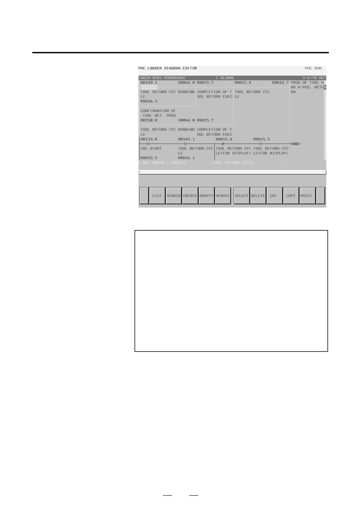
On the ladder diagram editing screen, a ladder program can be edited, and
its operation can be modified. To display the ladder diagram editing
Ladder diagram editing
screen, press the [EDIT] soft key on the ladder diagram display screen.
screen
On the ladder diagram editing screen, the following editing operations
can be performed on a ladder program:
D Net-by-net deletion
[DELETE]
D Net-by-net movement
[CUT] and [PASTE]
D Net-by-net copy
[COPY] and [PASTE]
D Changing the address of a contact or coil
“Bit address” + INPUT key
D Modifying a function instruction parameter
“Numeric value/byte address” + INPUT key
D Adding a new net
[CREATE]
D Modifying a net figure
[MODIFY]
D Reflecting the results of editing
[UPDATE]
D Restoring the pre-editing state
[RESTOR]
472
B-63525EN/02
7.INTERFACE BETWEEN CNC AND PMC
Ladder diagram editing screen
CAUTION
1
A ladder can be edited, regardless of whether operation is
in progress or stopped. Before an edited ladder can be
executed, however, the ladder must be updated. Press the
[UPDATE] soft key or update the ladder when exiting from
the ladder diagram editing screen.
2
If the power is turned off without writing an edited sequence
program to the flash ROM, the results of editing are cleared.
On the input/output screen, write an edited sequence
program to the flash ROM. If you specify “YES” for the
setting item “Save after Edit” on the PMC parameter setting
screen or set K902#0 to 1, a message for confirming
whether to write an edited sequence program to the flash
ROM upon completion of editing is displayed.
473
7. INTERFACE BETWEEN CNC AND PMC
B-63525EN/02
Screen manipulation
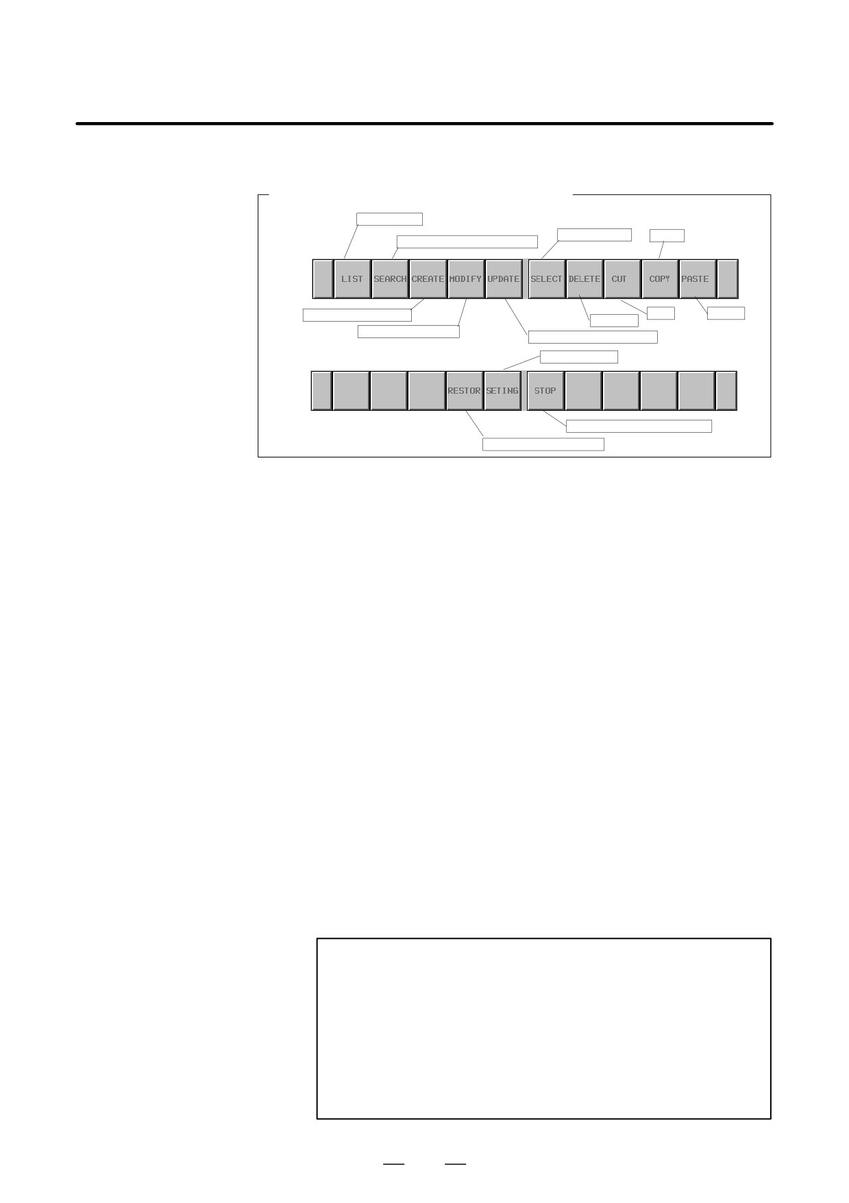
Soft keys on the ladder diagram editing screen
Program list
Net selection
Copy
Switching to search soft keys
Addition of a new net
Cut
Paste
Deletion
Modification of a net
Reflection of modifications
Screen setting
Sequence program start/stop
Discarding modifications
Soft keys on the ladder diagram editing screen
(a) Manipulation using soft keys
1
[LIST] Calling the program list editing screen
This soft key calls the program list editing screen. The program list
editing screen enables you to select a subprogram to be edited on
the ladder diagram editing screen.
2
[SEARCH] Search/jump menu
This soft key displays the soft keys for search. To return to the main
soft key display, use the return key [<]. The method of using the
soft keys for search is the same as for the ladder diagram display
screen.
3
[MODIFY] Calling the net editing screen
This soft key calls the net editing screen to modify the structure of
a selected net.
4
[CREATE] Creating a new net
This soft key adds a new net at the location where the cursor is
placed. The screen display switches to the net editing screen.
Create a net to be added.
5
[UPDATE] Reflecting modifications
This soft key reflects the results of editing in the ladder being
executed. When all modifications have been reflected normally,
the execution of the edited ladder starts.
WARNING
Use special care when modifying the ladder program being
executed. If the ladder program being executed is modified
incorrectly, the timing for reflecting modifications is
incorrect, or the machine state is improper, the machine
may operate unexpectedly. Before reflecting modifications,
be sure to check that the modifications are correct, that the
machine state is proper, and that there is no person near the
machine.
474
B-63525EN/02
7.INTERFACE BETWEEN CNC AND PMC
6
[SELECT] Selection of multiple nets
This soft key is used to specify multiple nets when editing such as
deletion, cut, or copy is performed. Determine the start point of a
selection range with the [SELECT] soft key, then specify the end
point of the selection range by moving the cursor or by using the
search function. After net selection, perform editing with editing
soft keys. While multiple nets are selected, the addition
information line displays information about the selection range.
7
[DELETE] Deleting a net
This soft key deletes selected a net. A net deleted with the
[DELETE] soft key is lost. If a net deleted by mistake with the
[DELETE] soft key needs to be restored, the entire ladder program
needs to be restored to the pre-editing state by using the
[RESTORE] soft key.
8
[CUT] Cutting a net
This soft key cuts a selected net. The cut contents are transferred
to the buffer for pasting, and are deleted from the ladder diagram.
The previous contents of the buffer are lost. When moving a net,
use this soft key together with the [PASTE] soft key.
9
[COPY] Copying a net
This soft key transfers a selected net to the buffer for pasting. No
change is made to the ladder diagram. The previous contents of the
buffer for pasting are lost. When copying a net, use this soft key
together with the [PASTE] soft key.
10 [PASTE] Pasting a net
This soft key inserts, at the cursor position, a net that has been
transferred to the buffer for pasting with the [CUT] soft key or the
[COPY] soft key. Press the [PASTE] soft key while a net is selected
with the [SELECT] soft key. The selected net is replaced with the
net held in the buffer for pasting. The contents of the buffer for
pasting are preserved until the power to the NC is turned off.
11 [RESTOR] Discarding modifications
This soft key discards the results of editing performed so far, and
restores the ladder present when the screen display switches to the
ladder diagram editing screen or the last update operation has been
completed. Use this soft key when restoration is difficult because
of incorrect editing.
12 [SETING] Screen setting
This soft key calls the setting screen for the ladder diagram editing
screen. Various settings for ladder diagram editing can be
modified. To return to the ladder diagram editing screen, use the
return key [<].
13 [START]/[STOP] Starting and stopping a ladder
These soft keys control ladder program execution. The [START]
soft key starts the execution of a ladder program. The [STOP] soft
key stops the execution of a ladder program. When modifications
have been reflected normally, the execution of the edited ladder
starts.
475

7. INTERFACE BETWEEN CNC AND PMC
B-63525EN/02
WARNING
Use special care when starting/stopping a ladder program.
If a ladder program is started/stopped when the start/stop
timing is incorrect, or the machine state is improper, the
machine may operate unexpectedly. Moreover, when a
ladder program is stopped, the safety mechanism and
monitoring based on the ladder program are disabled.
When starting/stopping a ladder program, be sure to check
that the machine state is proper, and that there is no person
near the machine.
14 [<] Ending editing
This soft key reflects the modifications made so far in the ladder
being executed, and ends editing. When you press a function key
such as the SYSTEM key during ladder program editing, data
being edited is discarded.
WARNING
Use special care when modifying the ladder program being
executed. If the ladder program being executed is modified
incorrectly, the timing for reflecting modifications is
incorrect, or the machine state is improper, the machine
may operate unexpectedly. Before reflecting modifications,
be sure to check that the modifications are correct, that the
machine state is proper, and that there is no person near the
machine.
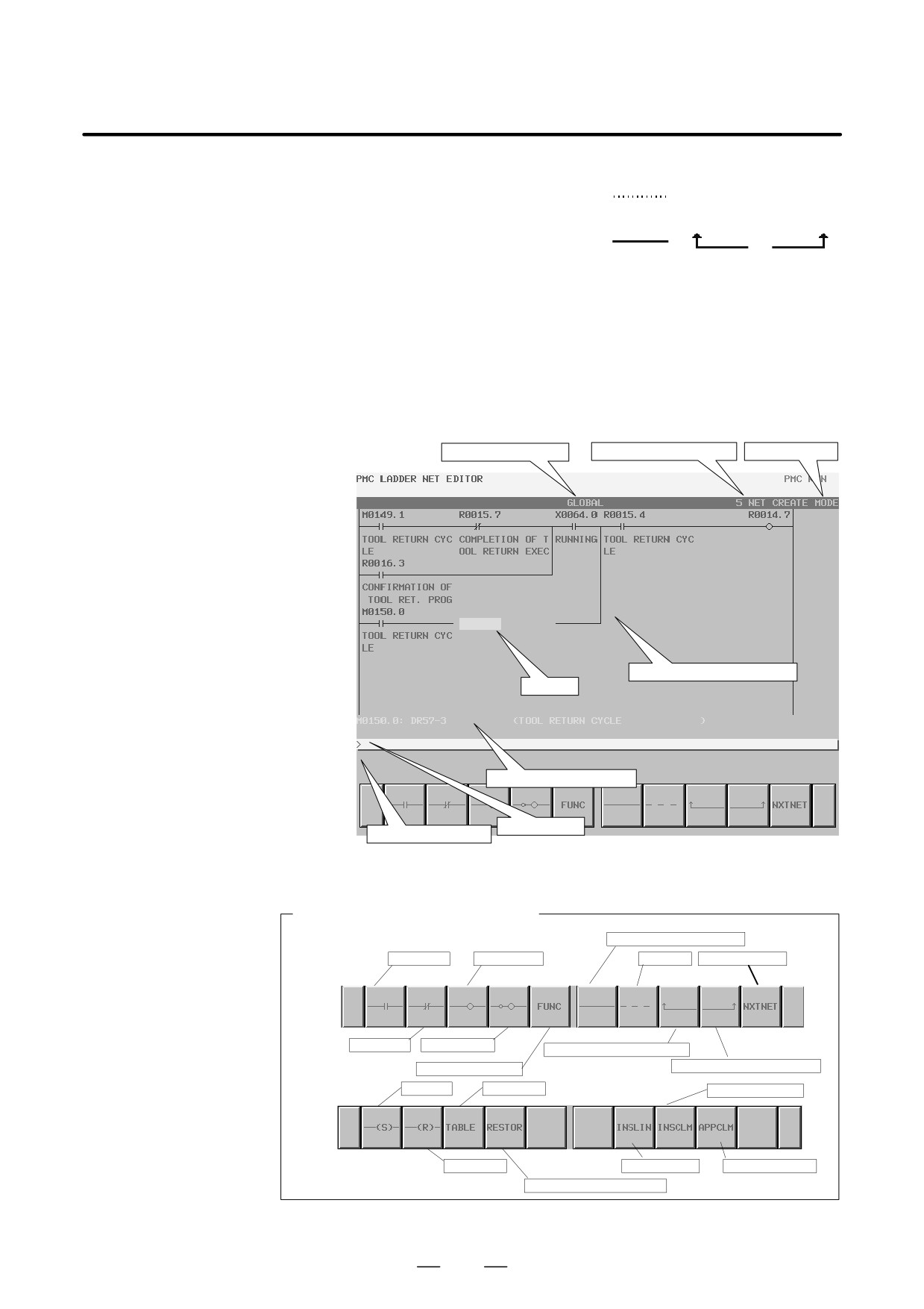
On the net editing screen, net editing operations such as the creation of
7.3.3.5
a new net and the modification of an existing net can be performed.
Net editing screen
1
Modification to an existing net:
If the net editing screen is displayed with the [MODIFY] soft key,
the mode (modification mode) for modifying the net indicated by
the cursor is set.
2
Addition of a new net:
If the net editing screen is displayed with the [CREATE] soft key,
the mode (creation mode) for creating a new net from a free state
is set.
The net editing screen allows the following editing operations:
D Placing a new contact/coil
“Bit address”
[
],
[
] and so forth
D Changing the type of a contact/coil
[
], [
]and so forth
D Placing a new function instruction
[FUNC]
D Changing the type of a function instruction
[FUNC]
476
B-63525EN/02
7.INTERFACE BETWEEN CNC AND PMC
D Deleting a contact/coil function instruction
[
]
D Adding/deleting a connection line
[
], [
], [
]
D Editing the function instruction data table
[TABLE]
D Line/column insertion
[INSLIN], [INSCLM], [APPCLM]
D Changing the address of a contact or coil
“Bit address” + INPUT key
D Changing a function instruction parameter
“Numeric value/byte address” + INPUT key
D Discarding the contents of editing
[RESTOR]
Displaysubprogram
Net number being edited
Editing mode
Ladder diagram display area
Cursor
Additional information line
Key input line
Message display line
Screen manipulation
Soft keys on the net editing screen
Horizontal connection line
Contact A
Positive coil
Deletion
To the next net
Contact B
Reverse coil
Left vertical connection line
Function instruction
Right vertical connection line
Set coil
Data table
Column insertion
Reset coil
Line insertion
Column addition
Discarding of modifications
Soft keys on the net editing screen
477
7. INTERFACE BETWEEN CNC AND PMC
B-63525EN/02
7.3.3.6
Signal trace function
(PMC-SB7)
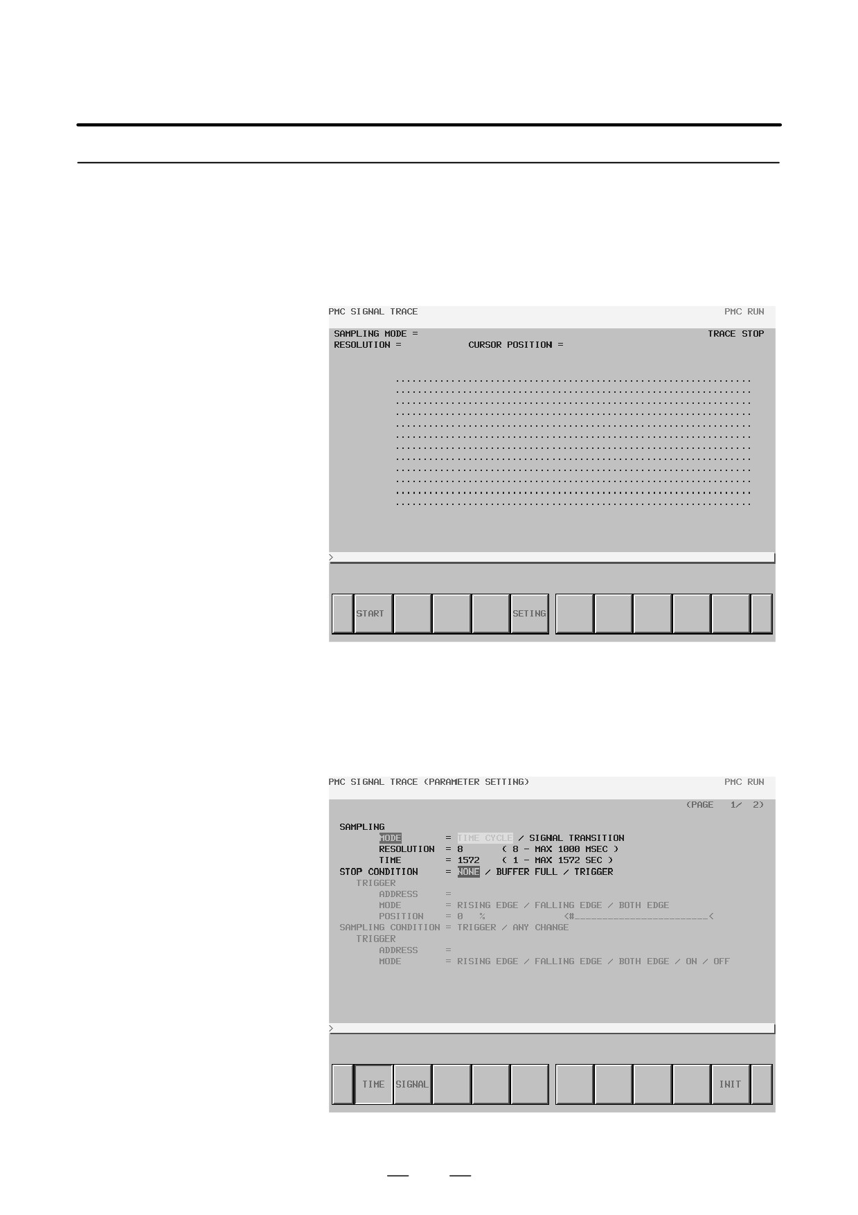
Signal trace screen
The signal trace screen is displayed when you press the [TRACE] soft key
(initial screen)
on the PMC diagnosis screen.
Signal trace screen (initial screen)
Trace parameter setting
When you press the [SETING] soft key on the signal trace screen, the trace
screen
parameter setting screen is displayed. The setting screen consists of
multiple pages. Use the page keys to switch between the pages.
Trace parameter setting screen (page 1)
478
B-63525EN/02
7.INTERFACE BETWEEN CNC AND PMC
(a) Sample/mode
Set a sampling mode.
D Period: A time period is used for sampling.
D Signal transition: A signal transition is used for sampling.
(b) Sampling/resolution
Set the resolution of sampling. The default is 8 ms.
The setting range is 8 ms to 1,000 ms.
An input value is rounded off to a multiple of 8 ms.
(c) Sampling/time
This item is displayed when “period” is selected for the sampling
mode. Set a desired sampling time.
The allowable input value depends on the setting of “resolution” and
the number of sampled signals. An allowable time range is indicated
at the right end.
(d) Sampling/frame
This item is displayed when “signal transition” is selected for the
sampling mode. Set a desired sampling count.
The allowable input value depends on the setting of “resolution” and
the number of sampled signals. An allowable time range is indicated
at the right end.
(e) Stop condition
Set a trace stop condition.
D None:
Trace operation is not automatically stopped.
D Buffer full: Trace operation is stopped when the sampling buffer
is full.
D Trigger:
Trace operation is stopped by a trigger.
(f) Stop condition/trigger/address
This item becomes settable when “trigger” is selected as the trace stop
condition. Set a trigger address for stopping trace operation.
(g) Stop condition/trigger/mode
This item becomes settable when “trigger” is selected as the trace stop
condition. Set a trigger mode for stopping trace operation.
D Rising: Trace operation is automatically stopped on a rising edge
of the trigger signal.
D Falling: Trace operation is automatically stopped on a falling edge
of the trigger signal.
D Transition: Trace operation is automatically stopped when the
trigger signal makes a transition.
(h) Stop condition/trigger/position
This item becomes settable when “trigger” is selected as the trace stop
condition. Set a position in the entire sampling time (or count) where
a stop trigger is initiated, by using a ratio to the sampling time (or
count). Set a proper value as required. For example, set a larger value
when checking the signal before the trigger condition, or set a smaller
value when checking the signal after the trigger condition.
Example: Graph display range when the sampling time is 10 seconds
and the sampling position is 10%
479
7. INTERFACE BETWEEN CNC AND PMC
B-63525EN/02
Trigger position
<-
1 second -><----
9 seconds
---->
|
|
|
–1
0
9 (SEC)
(i) Sampling condition
This item becomes settable when “signal transition” is selected as the
trace stop condition. Set a condition for sampling.
D Trigger: Sampling is performed when a sampling trigger
condition is satisfied.
D Transition: Sampling is performed when the signal at the sampling
address makes a transition.
(j) Sampling condition/trigger/address
This item becomes settable when “signal transition” is selected as the
sampling mode and “trigger” is selected as the sampling condition.
Set a sampling trigger address.
(k) Sampling condition/trigger/mode
This item becomes settable when “signal transition” is selected as the
sampling mode and “trigger” is selected as the sampling condition.
Set a trigger condition mode.
D Rising:
Sampling is performed on a rising edge of the trigger
signal.
D Falling:
Sampling is performed on a falling edge of the trigger
signal.
D Transition: Sampling is performed when the trigger makes a
transition.
D On:
Sampling is performed when the trigger signal is on.
D Off:
Sampling is performed when the trigger signal is off.
480
B-63525EN/02
7.INTERFACE BETWEEN CNC AND PMC
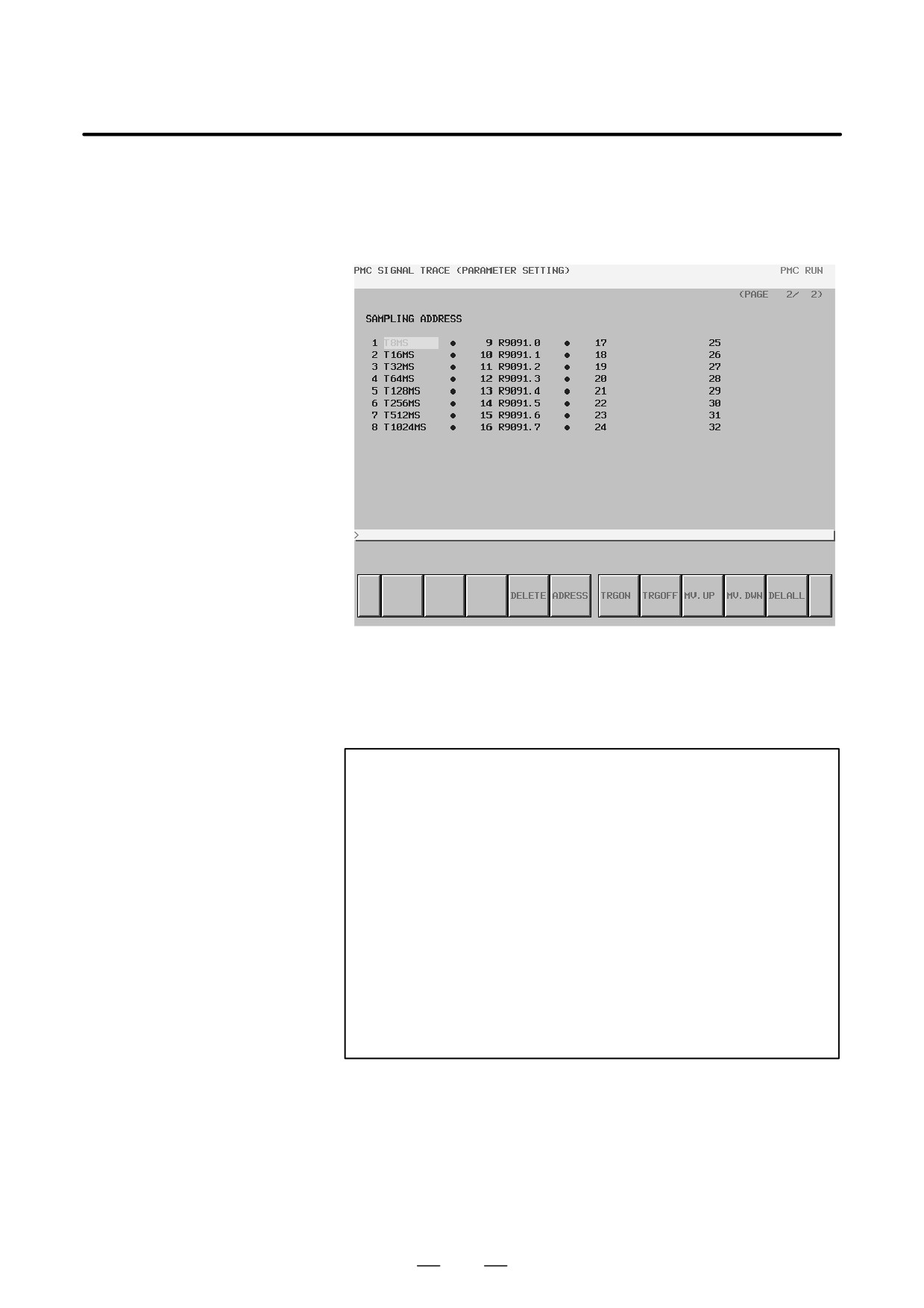
Sampling address
setting
(a) Address setting
On page 2 of the trace parameter setting screen, set the address of a
signal to be sampled.
Trace parameter setting screen (page 2)
Specify a bit address for a signal address. If a byte address is input,
bits 0 to 7 of the input address are input. Up to 32 signal address points
can be set.
NOTE
Depending on the number of points of signal addresses
subject to sampling and the sampling resolution, the
maximum allowable input value for the sampling time or
frame increases or decreases.
If the maximum allowable input value becomes smaller than
an existing sampling time or frame value, the message
below is displayed, and the setting is changed.
(In the
messages below, xxx represents a maximum allowable
input value.)
a) When a sampling time is set
“The sampling time has decreased to xxx seconds.”
b) When a sampling frame is set
“The sampling frame has decreased to xxx seconds.”
481