FANUC Series 16i/160i/160is-MODEL B, Series 18i/180i/180is-MODEL B, Series 21i/210i/210is-MODEL B. MAINTENANCE MANAUL - page 18
7. INTERFACE BETWEEN CNC AND PMC
B-63525EN/02
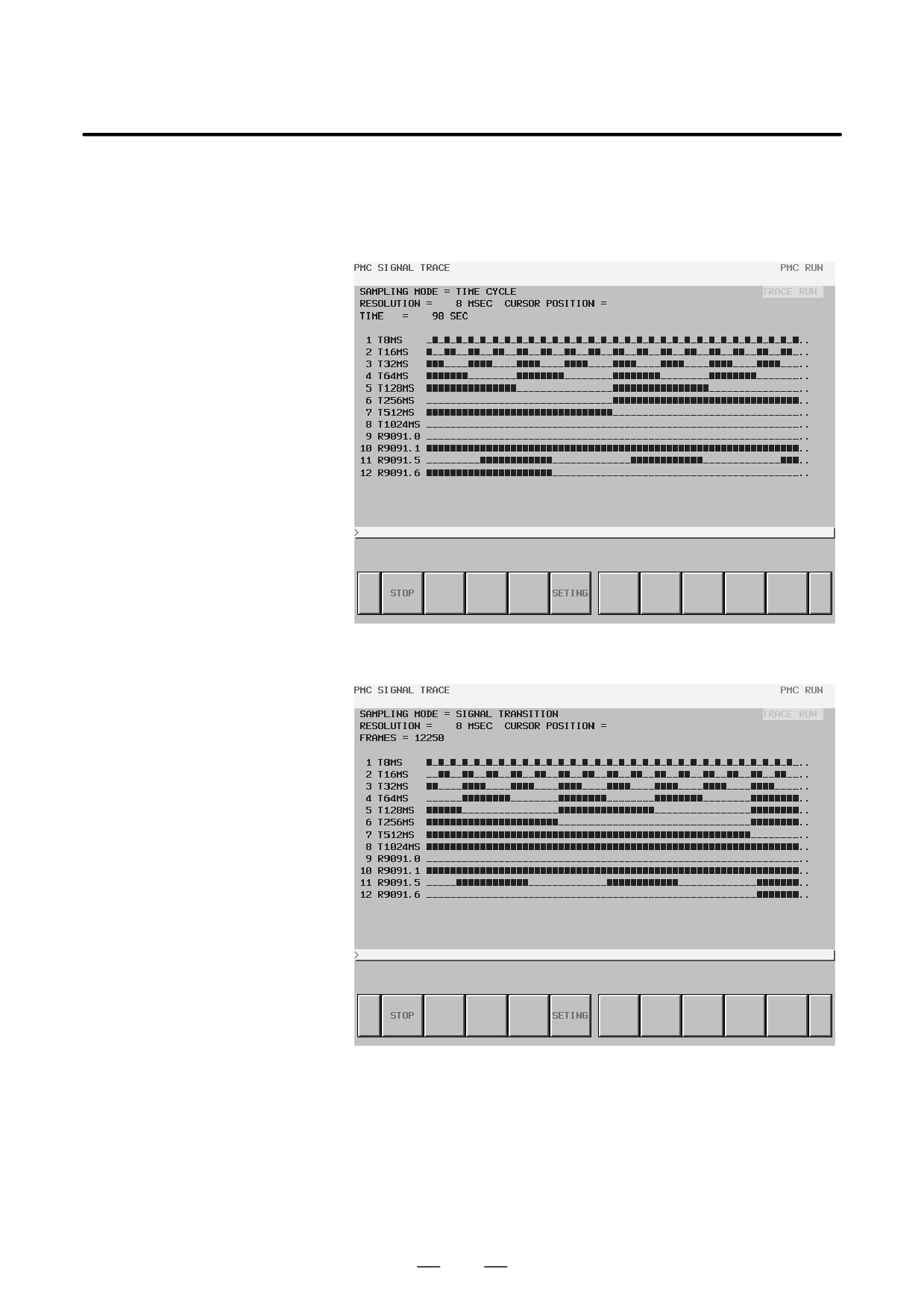
Trace execution
After trace parameter setting, press the [START] soft key on the trace
screen. Trace operation is started.
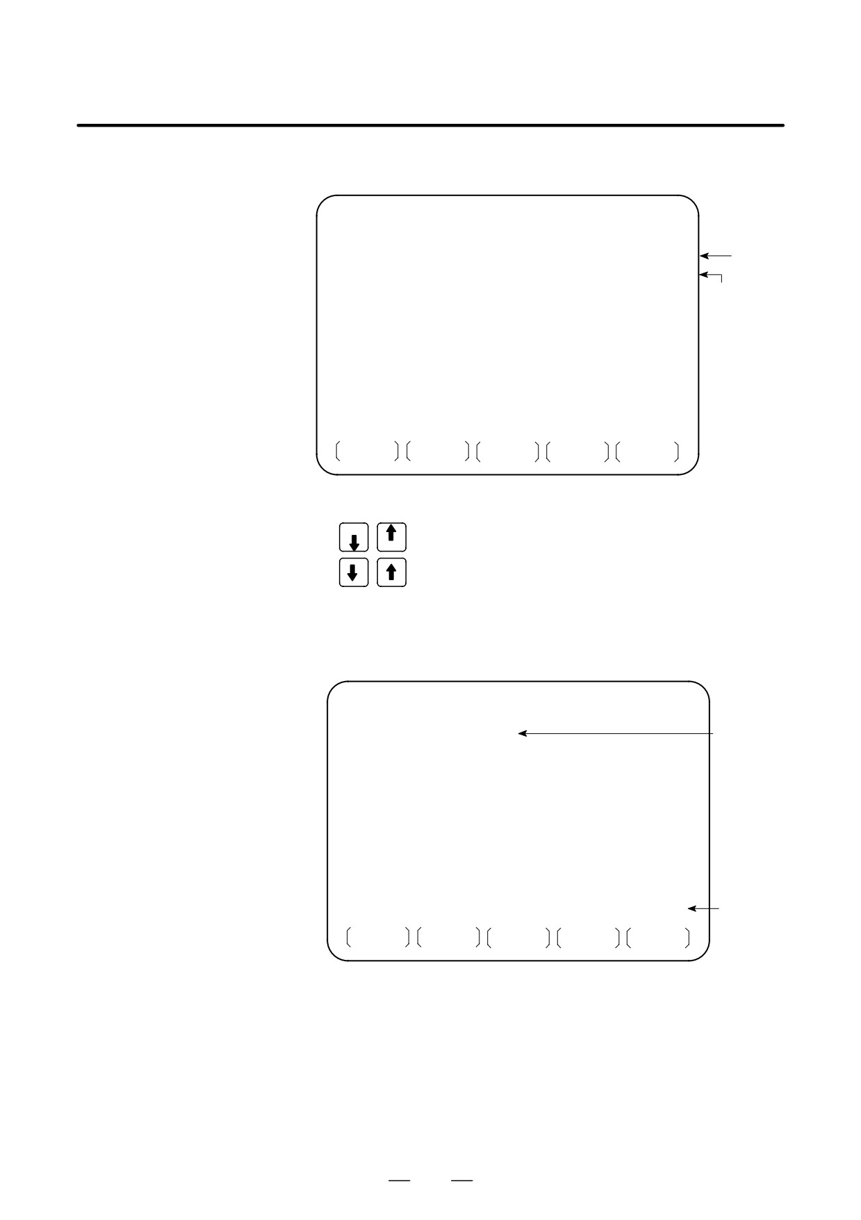
The screens below are examples of execution in the period mode and
signal transition mode.
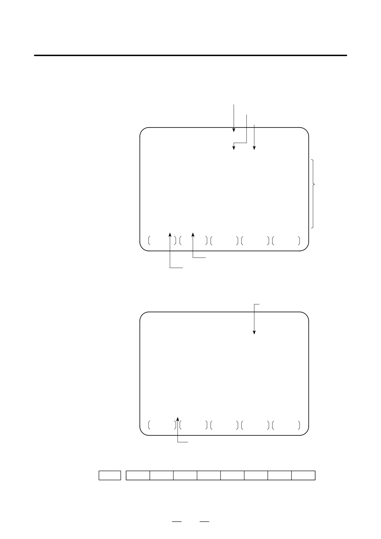
Signal trace execution screen (time cycle mode)
Signal trace execution screen (signal transition mode)
During trace execution, the results of trace operation are displayed in
real-time mode. When the trace stop condition set in the trace parameter
setting screen is satisfied, trace execution stops. Pressing the [STOP] soft
key also stops trace execution. In the signal transition mode, sampling
is performed when a signal transition is made. So, trace display is not
updated until a trigger signal transition is made.
482
B-63525EN/02
7.INTERFACE BETWEEN CNC AND PMC
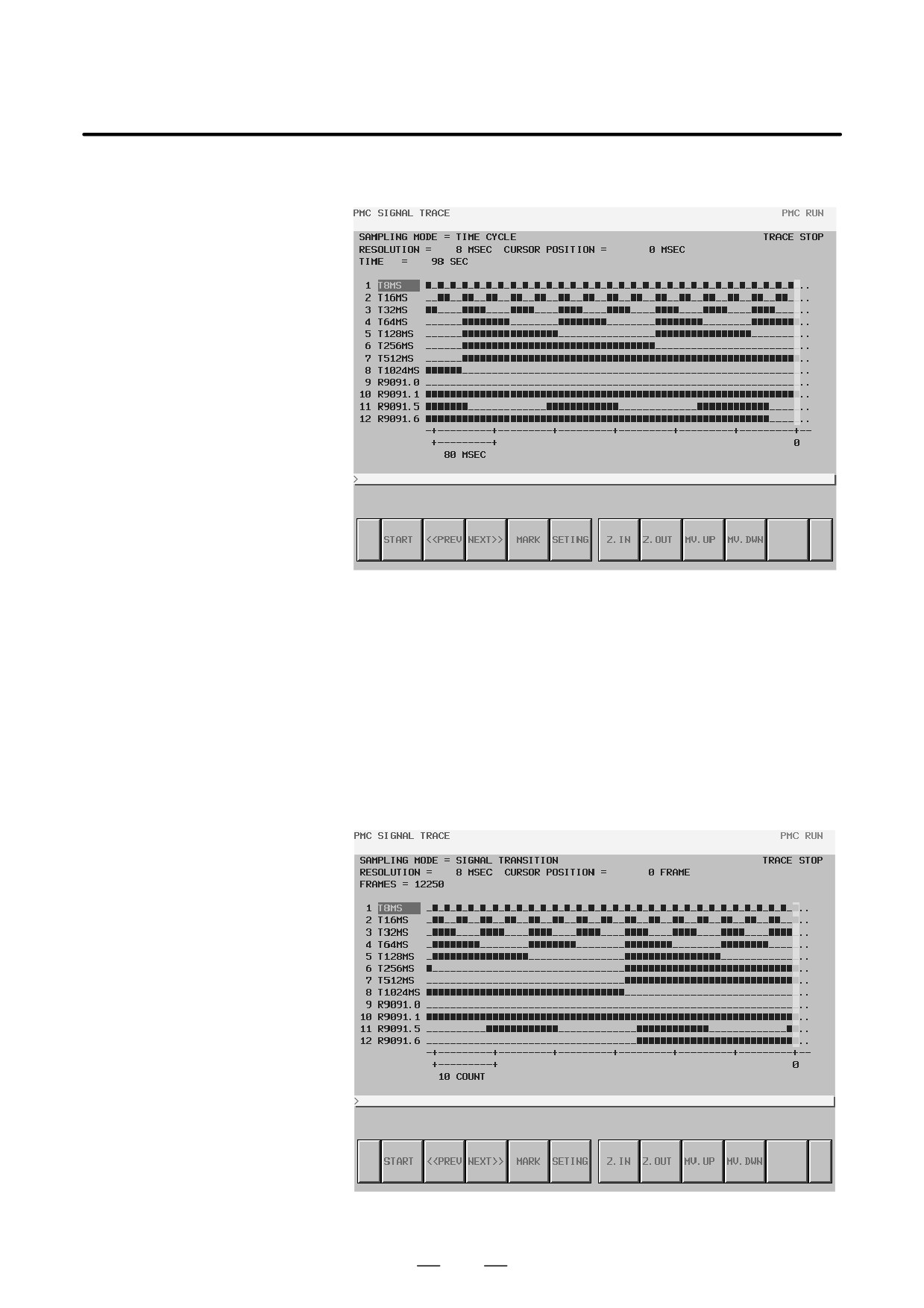
Checking trace results
Upon completion of trace execution, trace results can be checked.
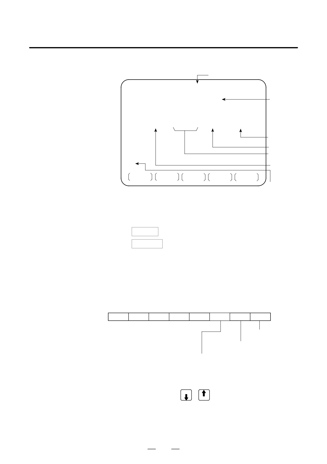
Signal trace result screen (time cycle mode)
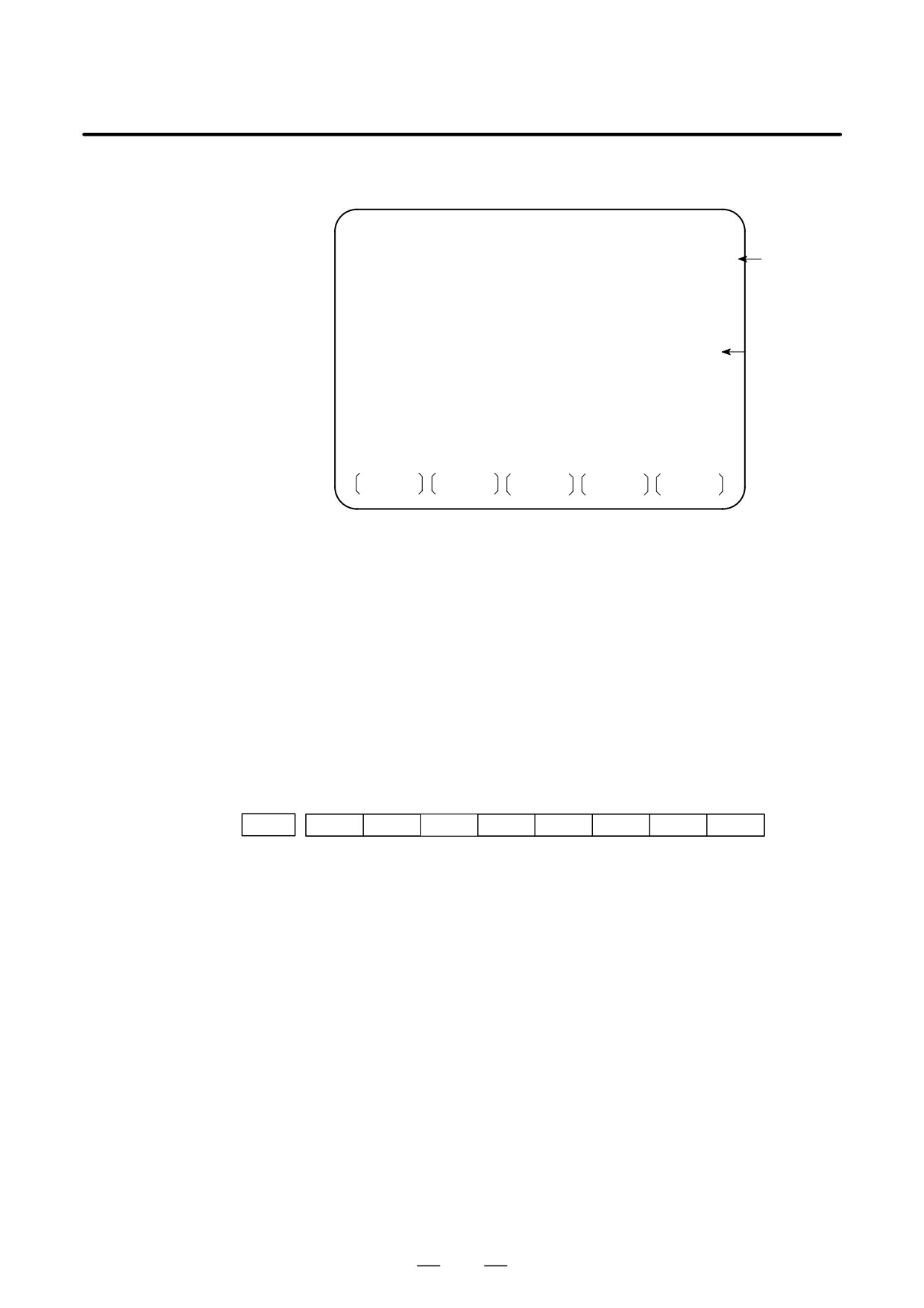
(a) Automatic selection range calculation display
When you press the [MARK] soft key, the cursor position at that time
is marked, and a mark cursor is displayed. If the mark cursor and the
current position cursor are placed at the same position, the current
position cursor takes priority. At the top of the screen, a mark position
indicating the mark cursor position and range information indicating
the range from the mark cursor position to the current position cursor
are displayed. These values change as the current position cursor
move. To cancel the range selection, press the [MARK] soft key again.
Signal trace result screen (mark cursor display)
483
7. INTERFACE BETWEEN CNC AND PMC
B-63525EN/02
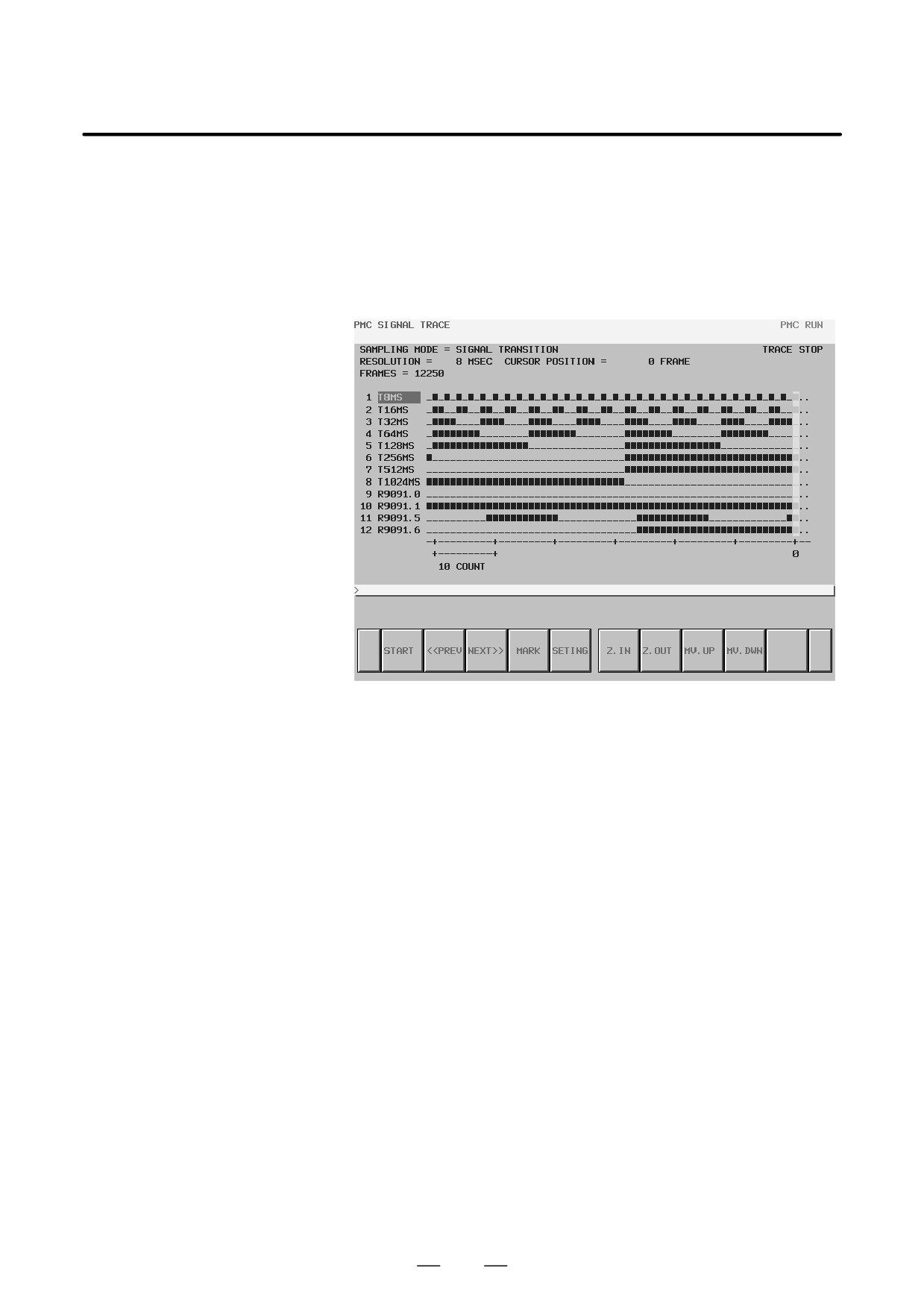
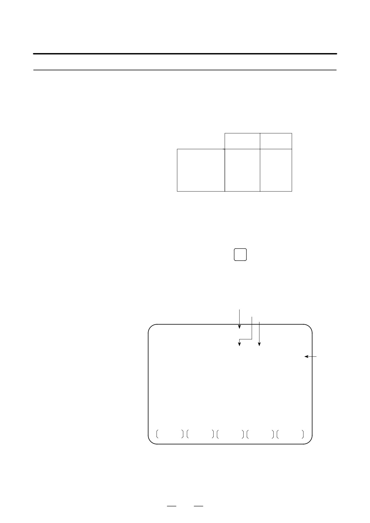
(b) Enlarged/reduced trace result data display
With the [Z.IN] or [Z.OUT] soft key, the graph can be enlarged or
reduced. This operation changes the scale value of one graph division.
Immediately after trace operation, the graph is enlarged to a maximum
extent. If reduced display disables ON/OFF changes from being
displayed precisely, “X” is used for graph display as shown below.
Reduced display is possible until all trace results are held on one page.
Signal trace result screen (reduced display)
484
B-63525EN/02
7.INTERFACE BETWEEN CNC AND PMC
7.3.4
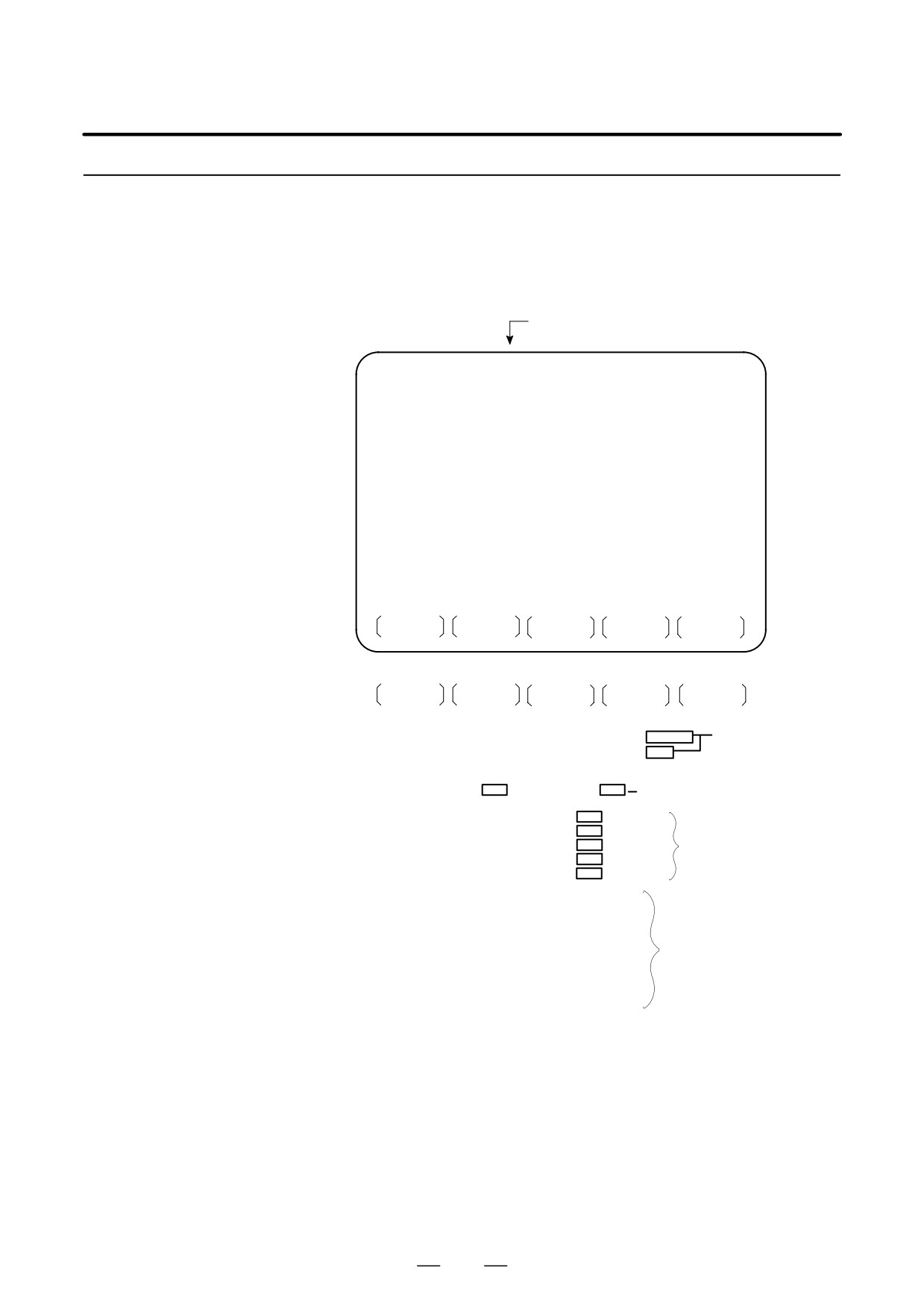
Press soft key [PMCDGN] then PMC’s diagnostic screen is displayed.
PMCDGN Screen
D TITLE screen
The title data registered when a ladder program is prepared is displayed.
Page number
PMC TITLE DATA #1
MONIT RUN
PMC PROGRAM NO.
:
EDITION NO.
:
PMC CONTROL PROGRAM
SERIES : 406G EDITION :01
PMC TYPE CONTROL : SB7 PROGRAM : SB7
MEMORY USED
:
KB
LADDER
:
KB
SYMBOL
:
KB
MESSAGE
:
KB
SCAN TIME
:
MSEC
SCAN MAX : 016 MS MIN : 008 MS
TITLE
STATUS
ALARM
TRACE
Other soft keys
M.SRCH
ANALYS
1st page PMC PROGRAM NO.
:
ÄÄÄ Set when PMC is
EDITION NO.
:
ÄÄÄprepared
PMC CONÄÄROGRAM
ÄÄ
SERIES :
EDITION :
Series and edition of PMC
control software
ÄÄ
ÄÄÄ
MEMORY USED
:
KB
LADDER
ÄÄ
KB
Memory used and
SYMBOL
KB
execution time is
MESSAGE
ÄÄ
KB
displayed.
SCAN TIME
MSEC
ÄÄ
2nd page MACHINE TOOL BUILDER NAME :
MACHINE TOOL NAME :
CNC & PMC TYPE NAME :
PROGRAM DRAWING NO. :
Set when PMC
is prepared.
3rd page DATE OF DRAWING :
PROGRAM DESIGNED BY :
ROM WRITTEN BY :
REMARKS :
485
7. INTERFACE BETWEEN CNC AND PMC
B-63525EN/02
D STATUS screen
On/Off state of input/output signals and internal relay is displayed.
PMC SIGNAL STATUS
MONIT RUN
ADDRESS
7
6
5
4
3
2
1
0
ED7 ED6 ED5 ED4 ED3 ED2 ED1 ED0
Signal
G0000
0
0
0
0
1
0
1
0
name
ED15 ED14 ED13 ED12 ED11 ED10 ED9 ED8
Signal state
0:Off
G0001
0
0
0
0
0
0
0
0
1:On
ESTB EA6 EA5 EA4 EA3 EA2 EA1 EA0
G0002
0
0
0
0
0
0
0
0
Signal state
G0003
0
0
0
0
0
0
0
0
reverses for
FIN
signals with *.
G0004
0
0
0
0
0
0
0
0
0: On
1: Off
SEARCH
[Search Method]
• PAGE
key :Forward and Backward by screen
PAGE
•
key :Forward and Backward by diagnostic number
• To search a specified address or signal name, input an address number
or signal name and press [SEARCH].
D Alarm screen
Displays an alarm generated in PMC.
PMC ALARM MESSAGE
MONIT RUN
Alarm dis-
play
ER32 NO I/O DEVICE
For details
of alarms,
refer to
Appendix
A.2 List of
Alarms.
ALM
Blinked
TITLE
STATUS
ALARM
TRACE
486
B-63525EN/02
7.INTERFACE BETWEEN CNC AND PMC
D TRACE screen
Every time a specified signal changes, the signal status is memorized in
(PMC-SA1)
the trace memory. This function is useful for identifying intermittent
troubles.
1
Trace parameter screen
PMC SIGNAL TRACE
MONIT RUN
TRACE MODE
:
(0:1BYTE/1:2BYTE/2:WORD)
1ST TRACE ADDRESS CONDITION
ADDRESS TYPE
: (0:PMC/1:PHY)
ADDRESS
:
MASK DATA
:
2ND TRACE ADDRESS CONDITION
ADDRESS TYPE
: (0:PMC/1:PHY)
ADDRESS
:
MASK DATA
:
T.DISP
EXEC
Changes to a trace memory display screen (Screen on
the next page)
Select each item by cursor key
a.
TRACE MODE: Select the trace mode
0=Records changes of 1-byte signals
1=Records changes of independent 2-byte signals
2=Records changes of consecutive 2-byte signals
b.
ADDRESS TYPE:
0=PMC address is used for tracing address.
1=Physical address is used for tracing address.
(Mainly used for C-language program)
c.
ADDRESS:Set a tracing address.
d.
MASK DATA: The bits to be traced are specified by a hexadecimal
number (2 digits).
For example, to trace the signals at bit
7,6,5 and
0, set E1
(hexadecimal) to MASK DATA.
#7 #6 #5 #4 #3 #2 #1 #0
E1→
1
1
1
0
0
0
0
1
However, even if bit
4,3,2 and
1 changes, tracing
(memory
registration) cannot be done but signal status is memorized when a
tracing is executed.
[Correspondence of binary and hexadecimal number]
00002 : 016
00012 : 116
00102 : 216
00112 : 316
01002 : 416
01012 : 516
01102 : 616
01112 : 716
10002 : 816
10012 : 916
10102 : A16
10112 : B16
11002 : C16
11012 : D16
11102 : E16
11112 : F16
487
7. INTERFACE BETWEEN CNC AND PMC
B-63525EN/02
2
Trace memory contents display screen
PMC SIGNAL TRACE
MONIT RUN
Trace
1ST ADDRESS=X008(E1)
2ND ADDRESS=G000(FF)
address
NO.
76543210
76543210
and mask
data(in pa-
0000
rentheses)
0001
I ** ** ***
* ** ** ***
I I* ** ***
* ** ** ***
0003À *ÀI * * * *À**ÀÀÀ*À* *À* * * * *ÀÀ
Latest status
0004
I mark : 1
* mark : 0
0005
0006
0007
0008
TRCPRM
STOP
10″LCD/14″CRT is dis-
played by 1 and 0.
a. Soft key [TRCPRM]: Return to the trace parameter setting screen
(screen of previous page)
b. Soft key [EXEC]:
Starts tracing.
Trace memory is cleared and each time a
specified signal changes, its status is recorded.
Trace memory is 256 bytes and if tracing is
executed 128 times by 2-byte tracing, tracing
is executed again from the head of memory.
c. Soft key [STOP]:
Ends the tracing.
*The tracing parameters are held even if the power is turned off.
#7
#6
#5
#4
#3
#2
#1
#0
K017
ÀÀÀÀ
0 : Tracing starts by [
#5
EXEC].
1 : Tracing starts automatically after power on
488
B-63525EN/02
7.INTERFACE BETWEEN CNC AND PMC
7.3.5
PMCPRM Screen
D Inputting PMC
parameters from the MDI
1
Set to MDI mode or emergency stop state.
2
Set PARAMETER WRITE (on setting screen) to 1 or set the program
protect signal (KEY4) to 1.
PWE
KEY4
Timer
f
-
Counter
f
f
Either one
Keep relay
f
-
Data table
f
f
Either one
3
Press a soft key and select a required screen.
[TIMER]
:Timer screen
[COUNTR] :Counter screen
[KEEPRL] :Keep relay screen
[DATA]
:Data table screen
4
Press cursor key and move the cursor to a desired number.
INPUT
5
Input a numeric key and press
key and data is input.
6
After the data is input, set PARAMETER WRITE or KEY4 on setting
screen to 0.
D TIMER screen
This screen is used for setting timer time of the functional instruction
(SUB 3).
Page no. (screen is scrolled by page key)
Timer no. specified by functional instruction
Address specified by ladder
PMC PARAMETER (TIMER) #001
MONIT RUN
NO. ADDRESS DATA
NO. ADDRESS DATA
01
T00
480
11
T20
0
Timer
delay
02
T02
960
12
T22
0
time
03
T04
0
13
T24
0
(msec)
04
T06
0
14
T26
0
05
T08
0
15
T28
0
06
T10
0
16
T30
0
07
T12
0
17
T32
0
08
T14
0
18
T34
0
09
T16
0
19
T36
0
10
T18
0
20
T38
0
TIMER
COUNTR
KEEPRL
DATA
Timer set time : Timer no. 1-8 is max. 1572.8 sec and its accuracy is
48ms.
Timer no. 9 is max. 262.1 sec and its accuracy is 8ms.
489
7. INTERFACE BETWEEN CNC AND PMC
B-63525EN/02
D COUNTER screen
This screen sets and displays max. value of counter and current value of
the counter instruction (SUB 4).
Page no. (screen is scrolled by page key)
Max. value of counter (Minimum
value is specified by counter ins.)
Current value of counter
PMC PARAMETER (COUNTER)#001
MONIT RUN
NO. ADDRESS
PRESET CURRENT
01
C00
100
1
PRESET
02
C04
50
2
and CUR-
RENT
03
C08
0
0
can be set
04
C12
0
0
up to
05
C16
0
0
9999, re-
spectively.
06
C20
0
0
07
C24
0
0
08
C28
0
0
09
C32
0
0
10
C36
0
0
TIMER
COUNTR
KEEPRL
DATA
Address specified by ladder
Counter number specified by func-
tional instruction
D KEEP RELAY screen
Address specified by ladder
PMC PARAMETER (KEEP REALAY) #001
MONIT RUN
NO. ADDRESS DATA
NO. ADDRESS DATA
01 K00
00000000
11 K10
00000000
02 K01
00000000
12 K11
00000000
03 K02
00000000
13 K12
00000000
04 K03
00000000
14 K13
00000000
05 K04
00000000
15 K14
00000000
06 K05
00000000
16 K15
00000000
07 K06
00000000
17 K16
À00000000
08 K07
00000000
18 K17
À00000000
09 K08
00000000
19 K18
À00000000
10 K09
00000000
20 K19
00000000
ÀÀÀÀ
TIMER
COUNTR
KEEPRL
DATA
Address specified by ladder
ÀÀ
Used by PMC system
ÀÀ
Nonvolatile memory control
#7
#6
#5
#4
#3
#2
#1
#0
À
K016 ÀÀÀÀÀÀ
#7(MWRTF2) : For checking the writing status in nonvolatile memory
#6(MWRTF1) : Writing status in nonvolatile memory
490
B-63525EN/02
7.INTERFACE BETWEEN CNC AND PMC
D DATA TABLE screen
1
Data table setting screen
No. of screen
PMC DATA TBL CONTROL #001
MONIT RUN
GROUP TABLE COUNT =
2
No. of
data table
NO.
ADDRESS
PARAMETER TYPE NO.OF DATA
groups
001
D0000
00000000
0
10
002
D0020
00000011
1
20
003
004
No. of
005
data table
Data length
006
Table
007
parameter
008
Data table
head ad-
dress
G.DATA
G.CONT
NO.SRH
INIT
Group no. of
data table
a. Soft key [G.DATA] : Select data display screen of data table.
(Next screen)
b.
NO. OF GROUPS
[G.CONT]: Set the no. of groups of data table.
c.
Group No.
[NO.SRH]: Move the cursor to a specified group.
d. Soft key [INIT]: Initializes the setting of data table.
No. of groups is 1, ADDRESS is D0000, PARAMETER is 0000000,
TYPE is 0, NO. OF DATA is 1860.
This operation is done usually when a sequence program is prepared.
When PMC parameters are set, internal parameters are not affected.
PARAMETER
#7
#6
#5
#4
#3
ÀÀ#2ÀÀ#1ÀÀ#0ÀÀ
ÀÀÀÀÀÀÀÀÀ
0 : Binary format
1 : BCD format
0 : Without protection for input
1 : With protection for input
0 : Binary format or BCD format (Bit 0 is valid)
1 : Hex format (Bit 0 is not valid)
TYPE
0 : 1-byte length
1 : 2-byte length
2 : 4-byte length
e. Using the page key PAGE
/
, next screen/previous screen can be
PAGE
selected.
491
7. INTERFACE BETWEEN CNC AND PMC
B-63525EN/02
2
Data display screen
Group number
Page number
PMC PRM (DATA) 001/001
MONIT RUN
NO.
ADDRESS
DATA
000
D0000
0
001
D0001
0
002
D0002
0
003
D0003
0
004
D0004
0
005
D0005
0
006
D0006
0
007
D0007
0
008
D0008
0
009
D0009
0
C.DATA
G-SRCH
SEARCH
a. Soft key [C.DATA] :Returns to the data table setting screen.
(Previous screen)
b.
Group No.
[G-SRCH] : Head of the specified group is selected.
c.
Address
[SEARCH]: Searches an address in a group currently
selected.
7.3.6
Setting Screen
Setting screen for PMC-SB7
492
B-63525EN/02
7.INTERFACE BETWEEN CNC AND PMC
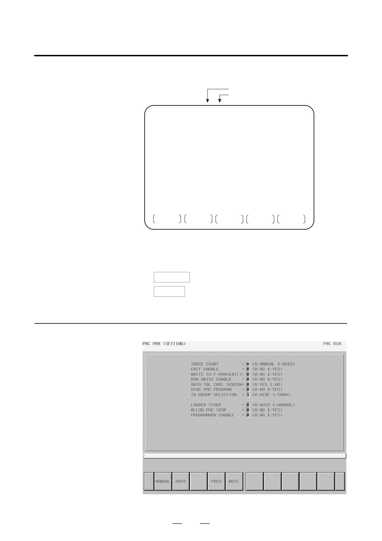
D
Trace function start (PMC-SB7:K906.5)
Manual (0): The trace function starts trace operation when the
[EXEC] soft key is pressed.
Automatic (1): The trace function starts sampling automatically after
the power is turned on.
D
Enable editing (PMC-SB7:K901.6, PMC-SA1:K18.6)
No (0):
The editing of a sequence program is disabled.
Yes (1):
The editing of a sequence program is enabled.
D
Save after editing (PMC-SB7:K902.0, PMC-SA1:K19.0)
No (0):
After ladder editing, the F-ROM is not written to
automatically.
Yes (1):
After ladder editing, the F-ROM is written to
automatically.
D
Enable memory write (PMC-SB7:K900.4, PMC-SA1:K17.4)
No (0):
The forcing function and the override function are
disabled.
Yes (1):
The forcing function and the override function are
enabled.
D
Data table GRP setting display (PMC-SB7:K900.7, PMC-SA1:K17.7)
Yes (0):
The PMC parameter data table control screen is
displayed.
No (1):
The PMC parameter data table control screen is not
displayed.
D
Disable PMC program read (PMC-SB7:K900.0, PMC-SA1:K17.0)
No (0):
The reading of a sequence program is enabled.
Yes (1):
The reading of a sequence program is disabled.
D
IO Group selection (PMC-SB7:K906.1)
Hide (0):
The I/O assignment data selection function setting
screen is not displayed.
Show (1):
The I/O assignment data selection function setting
screen is displayed.
D
PMC program execution (PMC-SB7:K900.2, PMC-SA1:K17.2)
Automatic (0): After the power is turned on, a sequence program is
automatically executed.
Manual (1): A sequence program is executed by pressing the
sequence program execution soft key.
D
Enable PMC stop (PMC-SB7:K902.2, PMC-SA1:K19.2)
No (0):
The execution/stop operation of a sequence program
is disabled.
Yes (1):
The execution/stop operation of a sequence program
is enabled.
D
Enable the programmer function (PMC-SB7:K900.1, PMC-SA1:
K17.1)
No (0):
The built-in programmer function is not operated.
Yes (1):
The built-in programmer function is operated.
493
7. INTERFACE BETWEEN CNC AND PMC
B-63525EN/02
7.3.7
Online Setting
7.3.7.1
Online setting screen
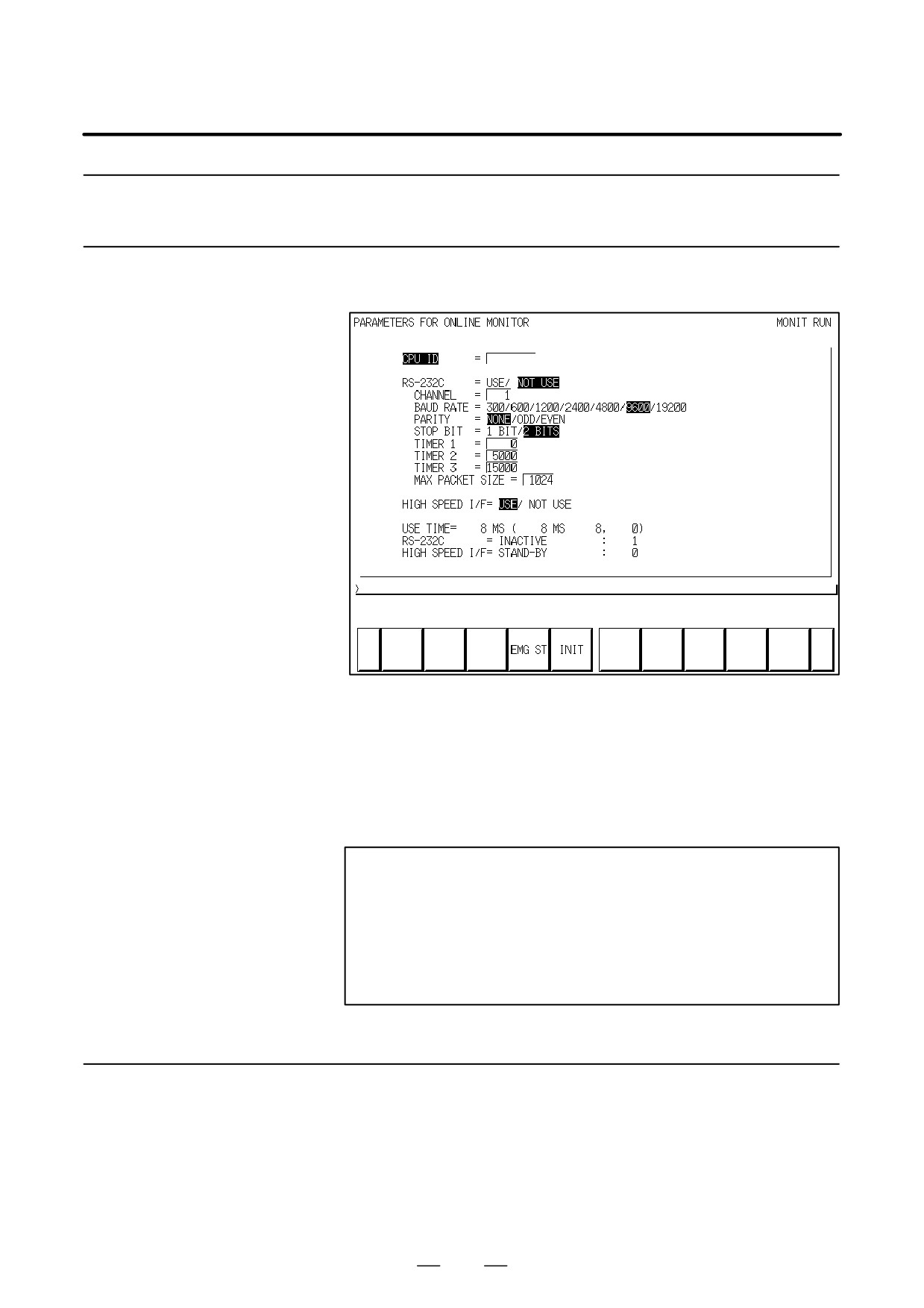
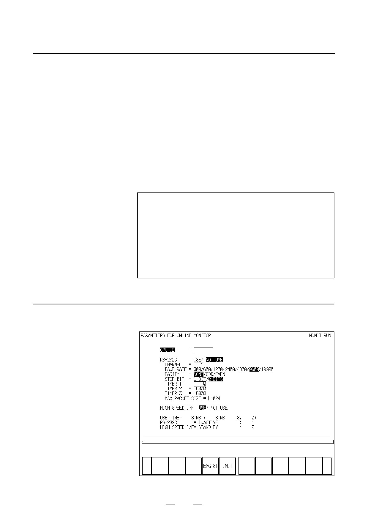
Fig. 7.3.7.1 Online monitor setting screen
Meanings of Soft key
EMG ST: Terminates communication forcibly. Use this key if
communication becomes abnormal and the connection
cannot be terminated normally.
INIT:
Initializes the parameters to their default values.
NOTE
1
In case of configuration of CNC with which neither Ethernet
nor HSSB is available, the item of ”HIGH SPEED I/F” is not
displayed.
2
In case of display which has 5+2 soft key, two pages are
used for this setting screen.
Switch the page by < Page Up > or <Page Down> key.
7.3.7.2
To display the soft key [MONIT] in the PMC main menu screen, set
”PROGRAMMER ENABLE” to ”YES” in the setting screen. When
Setting of online
pushing the soft key [MONIT]→[ONLINE], the online setting screen is
connection
displayed.
1
Case of connection by RS-232C (FANUC LADDER-II, FANUC
LADDER-III)
(1) Check that ”NOT USE” is selected at the ”RS-232C” item.
494
B-63525EN/02
7.INTERFACE BETWEEN CNC AND PMC
(2) Set the parameter of ”CHANNEL” and ”BAUD RATE”.
(3) Move the cursor to the ”RS-232C” item with Up or Down Cursor
key.
(4) Select ”USE” with Left or Right Cursor key.
2
Case of connection by Ethernet (FANUC LADDER-III, Ladder
Editing Package)
(1) Move the cursor to the ”HIGH SPEED I/F” item with Up or Down
Cursor key.
(2) Select ”USE” with Left or Right Cursor key.
3
Case of connection by HSSB (Ladder Editing Package)
(1) Move the cursor to the ”HIGH SPEED I/F” item with Up or Down
Cursor key.
(2) Select ”USE” with Left or Right Cursor key.
NOTE
1
When both ”RS-232C = USE” and ”HIGH SPEED I/F =
USE” are selected, the PMC system will communicate with
the application which is connected at first. If PMC system is
already connecting with an application, it can not connect
with other applications.
2
When you use the online function by Ethernet, the setting
of Ethernet parameters at CNC is necessary in advance.
3
Loader control function can not connect with FANUC
LADDER-III or Ladder Editing Package by Ethernet.
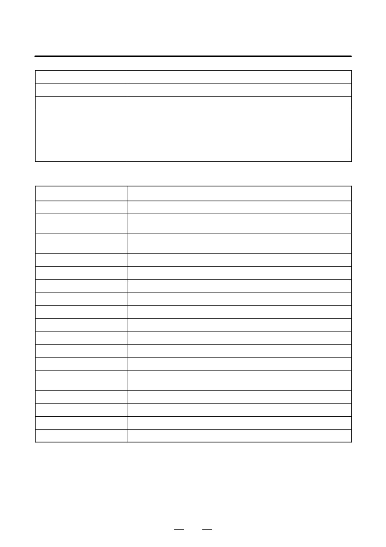
The communication status of RS-232C and HIGH SPEED I/F are
7.3.7.3
displayed at the online monitor screen during the online communication.
Communication Status
Fig. 7.3.7.3 Online monitor setting screen
495
7. INTERFACE BETWEEN CNC AND PMC
B-63525EN/02
USE TIME
:
The maximum time in the communication processing is displayed.
RS-232C
:
The communication condition of RS-232C is displayed.
HIGH SPEED I/F
:
The communication condition of HIGH SPEED I/F is displayed.
Displayed during the communication with Ethernet board.
ETHER_BOARD
:
The IP address of the communication partner is displayed.
Displayed during the communication with embedded Ethernet.
EMB_ ETHERNET
:
The IP address of the communication partner is displayed.
HSSB
:
Displayed during the communication with HSSB.
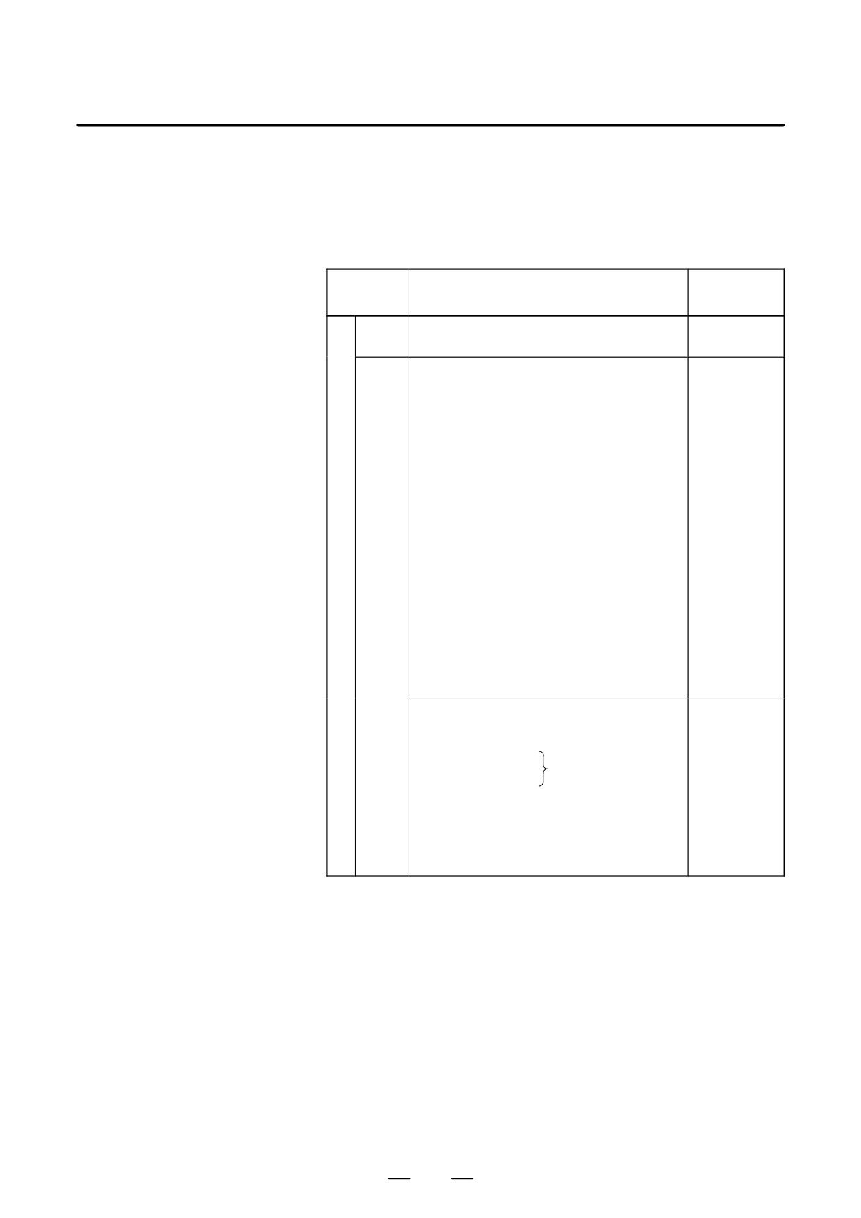
The display messages and the meanings are shown in the table of below.
Displayed messages
Meanings
INACTIVE
The communication is inactive.
STOPPING
The communication is being stopped.
(Wait for the termination of communication)
STARTING
The communication is being started.
(Wait for the termination of communication over another communication path)
STAND-BY
The communication is active and in standby mode.
CONNECTED
The communication is active and being connected.
NO OPTION
The port can be not opened because there is not option of RS-232C.
BAD PARAMETER
Invalid open parameters are specified.
TIMEOUT ERROR
A time-out has occurred and communication is aborted.
TIMEOUT(K) ERROR
A time-out has occurred and communication is aborted.
BCC ERROR
A Block Check Code (packet parity) error has occurred.
PARITY ERROR
A parity error has occurred.
OVER-RUN ERROR
A reception overrun has occurred and the communication can not recover.
SEQUENCE ERROR
Packets are out of sequence.
(Incorrect procedure)
DATA ERROR
Incorrect packets have been received through retry process.
QUEUE OVERFLOW
The transmit/receive queue has overflowed.
DISCONNECTED
Communication has been terminated successfully.
NO CONNECTION
The cable is disconnected.
496
B-63525EN/02
7.INTERFACE BETWEEN CNC AND PMC
7.4
LIST OF SIGNALS BY
EACH MODE
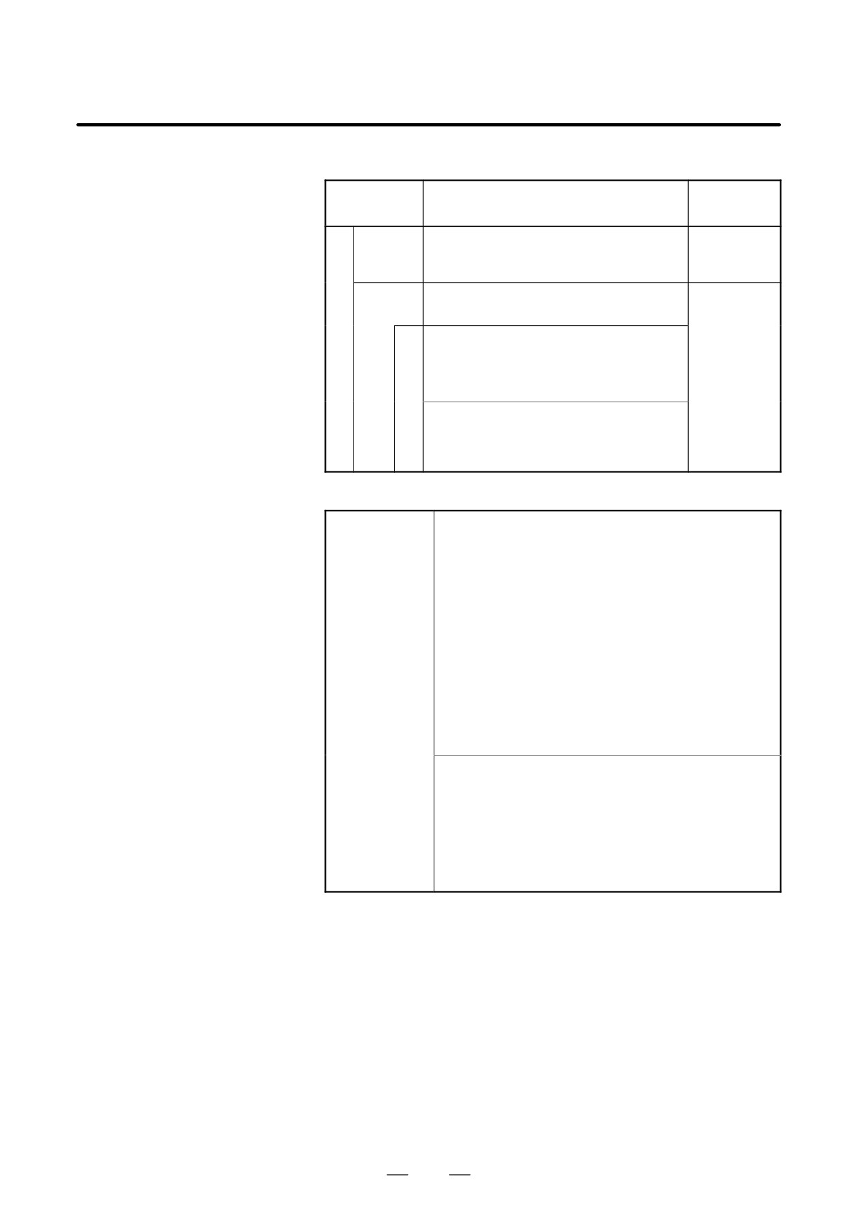
D Automatic operation
MODE
INPUT/OUTPUT SIGNAL
FEED RATE,
ETC
EDIT
[PMC ⇒ CNC]
KEY3(Program protect key)
[PMC ⇒ CNC)
[PMC ⇒ CNC]
ST
(Cycle start)
*FV0 to 7
*SP
(Feed hold)
(Feed rate over-
SBK
(Single block)
ride)
DRN
(Dry run)
*AFV0 to 7
BDT1 to 9
(Block delete)
(2nd feed rate
MIα
(Mirror image)
override)
STLK
(Start lock:16T/18T)
A
OVC
CDZ
(Chamfering:16T/18T)
U
(Override can-
SMZ
(In-positioncheck:16T/18T)
T
cel)
PN1 to 8
(External program no. search)
O
MINP
(External program input)
ROV1,ROV2,
M
HROV,
DNCI
(DNC input mode)
A
DMMC
(C direct operation)
*HROV0 to 6
T
HSα1A to D (Handle interrupt axis select)
(Rapid traverse
I
AFL
(Auxiliary function neglect)
override)
C
FIN, MFIN2, MFIN3
SOV0 to 7
MEM
(Auxiliary function complete)
(Spindle speed
O
MDI
MFIN, SFIN, TFIN, BFIN
override)
P
(High speed M/S/T function complete)
E
RMT
GR1, 2
(Gear input 16T/ 18T)
R
*SSTP
(Spindle stop)
A
SAR
(Spindle speed arrival)
T
SOR
(Spindleorientation)
I
O
[CNC ⇒ PMC]
N
STL
(Cycle start LED)
SPL
(Feed hold LED)
MF, M00 to M31
MF2, M200 to M215
(Miscellaneous
MF3, M300 to M315
function)
SF, S00 to S31
(Spindle speed function)
TF, T00 to T31
(Tool function)
BF, B00 to B31
(2nd miscellaneous func.)
DEN
(Distribution end)
OP
(automaticoperating)
GR1O to GR3O(Gear selection:16M/18M)
497
7. INTERFACE BETWEEN CNC AND PMC
B-63525EN/02
D Manual operation
MODE
INPUT/OUTPUT SIGNAL
FEED RATE,
ETC
Handle/
[PMC ⇒ CNC]
[PMC ⇒ CNC]
M
incremental
HSnA to D (Axis selection) n:1 to 3(No. of MPGs)
MP1, MP2
A
+α, -α
(Jog feed)
(Multiplier)
N
U
JOG
[PMC ⇒ CNC]
[PMC ⇒ CNC]
A
RT
(Rapid traverse)
*JV0 to 15
L
(Manual fee-
[PMC ⇒ CNC]
drate override)
O
ZRN(Reference position return mode)
+α, -α
(Man
P
[MT ⇒ CNC]
ual feed move
E
command)
R
Z
*DECα
(Reference position deceleration)
A
R
ROV1, ROV2
T
N
[CNC ⇒ PMC]
HROV
I
ZPα
*HROV0 to 6
O
ZP2α, ZP3α, ZP4α
(Rapid traverse
N
(Reference position return completion)
override)
D Others
[PMC ⇒ CNC]
MD1 to 4
(Mode selection)
*ESP
(Emergency stop)
KEY1 to 4
(Memory protection key)
MLK,MLKα (All axes/ each axis machine lock)
*IT,*ITα
(All axes/ each axis machine lock)
*"MITα
(interlock per axis and direction:M series)
STLK
(Start lock:T series)
*ABSM
(Manual absolute)
SVFα
(Servo off)
*FLWP
(Follow up)
ERS
(External reset)
RRW
(Reset & Rewind)
Others
EXLM
(Stored stroke limit external switching)
"LMα, RLSOT
(Software limit external setting M series)
*"Lα
(Overtravel limit)
*"EDα
(External deceleration of each axis)
[CMC ⇒ PMC]
MA
(NC ready)
SA
(Servo ready)
AL
(NC alarm)
RST
(Resetting)
BAL
(Battery alarm)
INPα
(In-position)
MVα
(Axis moving)
TAP
(Tapping)
498
B-63525EN/02
7.INTERFACE BETWEEN CNC AND PMC
(1) For 1-path control
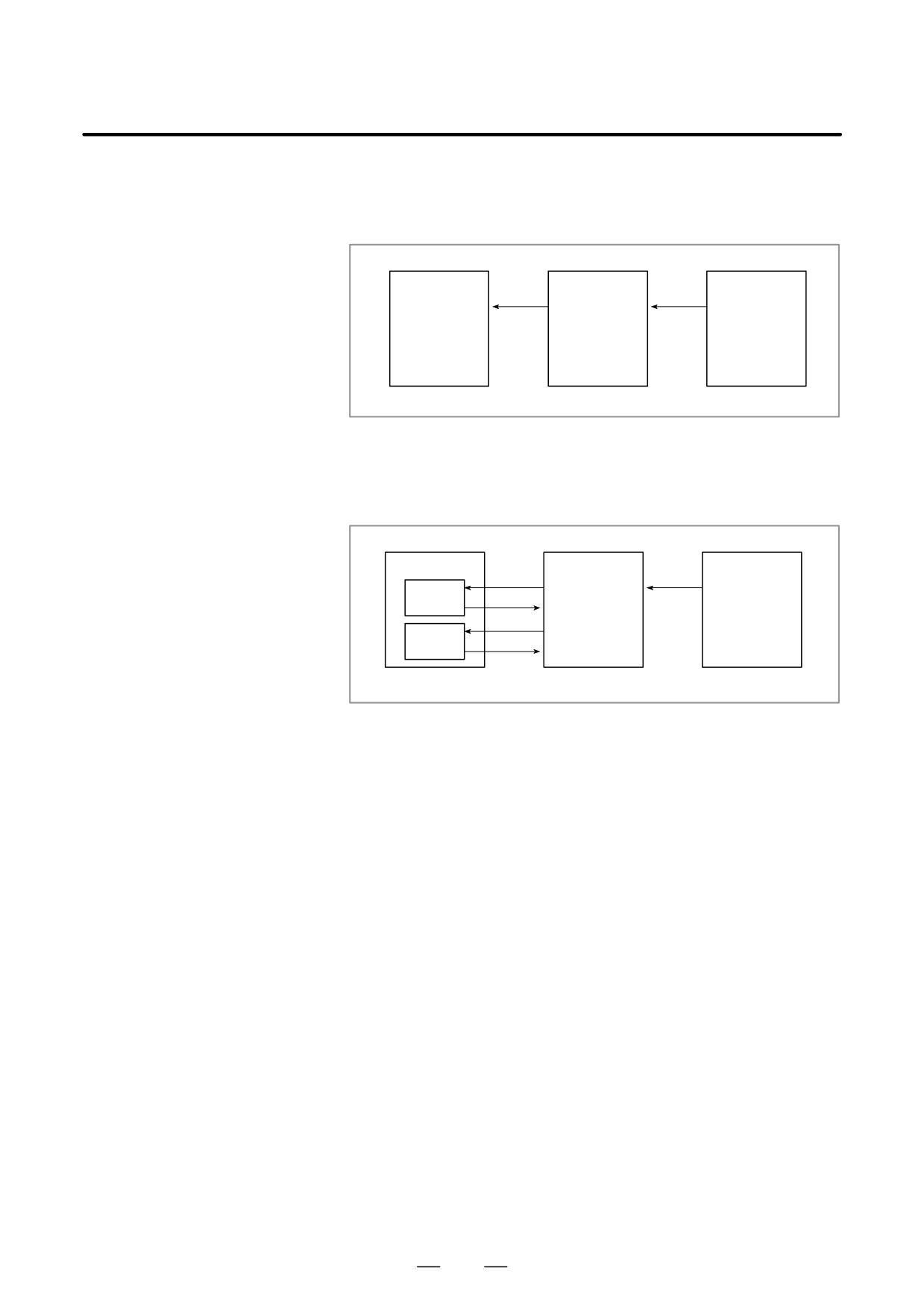
7.5
The relationship of the addresses of the interface signals transferred
LIST OF INPUT/
between the CNC and PMC are shown below.
OUTPUT SIGNALS
CNC
G000-
PMC
X000-
MT
F000-
Y000-
(2) For 2-path control
The relationship of the addresses of the interface signals transferred
between the CNC and PMC are shown below. Some signals common
to both paths are included in the signals of path 1.
CNC
PMC
MT
X000-
G000-
Path 1
F000-
Y000-
G1000-
Path 2
F1000-
499

7. INTERFACE BETWEEN CNC AND PMC
B-63525EN/02
D List of input/output
signals
f
:
Available
F
:
Available only with
2-path control
-
:
Unavailable
T
M
Symbol
Signal name
Address
series
series
*+ED1 to *+ED8
External deceleration signal
G118
f
f
*+L1 to *+L8
Overtravel signal
G114
f
f
*-ED1 to *-ED8
External deceleration signal
G120
f
f
*-L1 to *-L8
Overtravel signal
G116
f
f
*ABSM
Manual absolute signal
G006#2
f
f
*AFV0 to *AFV7
2nd feedrate override signal
G013
f
f
*BECLP
B-axis clamp completion signal
G038#7
-
f
*BEUCP
B-axis unclamp completion signal
G038#6
-
f
*BSL
Block start interlock signal
G008#3
f
f
*CHLD
Chopping hold signal
G051#7
-
f
*CHP8 to *CHP0
Chopping feedrate override signals
G051#0 to #3
-
f
*CRTOF
Automatic erase CRT screen display cancel signal
G062#1
f
f
*CSL
Cutting block start interlock signal
G008#1
f
f
*DEC1 to *DEC8
Deceleration signal for reference position return
X009
f
f
*EAXSL
Control axis selection status signal(PMC axis control)
F129#7
f
f
*ESP
X008#4
f
f
Emergency stop signal
*ESP
G008#4
f
f
*ESPA
G071#1
f
f
*ESPB
G075#1
f
f
Emergency stop signal (serial spindle)
*ESPC
G205#1
f
f
*ESPD
G267#1
f
f
*FLWU
Follow-up signal
G007#5
f
f
*FV0 to *FV7
Feedrate override signal
G012
f
f
*FV0E to *FV7E
Feedrate override signal (PMC axis control)
G151
f
f
*FV0O to *FV7O
Software operator's panel signal(*FV0 to *FV7)
F078
f
f
*HROV0 to *HROV6
1% step rapid traverse override signal
G096#0 to #6
f
f
*IT
Interlock signal
G008#0
f
f
*IT1 to *IT8
Interlock signal for each axis
G130
f
f
*JV0 to *JV15
Manual feedrate override signal
G010,G011
f
f
*JV0O to *JV15O
Software operator's panel signal(*JV0 to *JV15)
F079,F080
f
f
*PLSST
Polygon spindle stop signal
G038#0
f
-
*SCPF
Spindle clamp completion signal
G028#5
f
-
*SP
Feed hold signal
G008#5
f
f
*SSTP
Spindle stop signal
G029#6
f
f
500

B-63525EN/02
7.INTERFACE BETWEEN CNC AND PMC
T
M
Symbol
Signal name
Address
series
series
*SSTP1
G027#3
f
f
*SSTP2
G027#4
f
f
Individual spindle stop signals
*SSTP3
G027#5
f
f
*SSTP4
G026#6
f
f
*SUCPF
Spindle unclamp completion signal
G028#4
f
-
*TLV0 to *TLV9
Tool life count override signal
G049#0 to G050#1
-
f
*TSB
Tailstock barrier select signal
G060#7
f
-
+EXL1 to +EXL8
Axis direction dependent stored stroke limit switch signal
G104
f
f
+J1 to +J8
Feed axis and direction selection signal
G100
f
f
+J1O to +J4O
Software operator's panel signal(+J1 to +J4)
F081#0,#2,#4,#6
f
f
+Jg, -Jg, +Ja, -Ja
Feed axis and direction selection signals
G086#0 to #3
f
f
+LM1 to +LM8
Stroke limit external setting signal
G110
-
f
+MIT1,+MIT2
Manual feed interlock signal for each axis
X004#2,#4
f
-
+MIT1,+MIT2
Tool offset write signal
X004#2,#4
f
-
+MIT1 to +MIT4
Interlock signal for each axis and direction
G132#0 to #3
-
f
+OT1 to +OT8
Stroke limit reached signals
F124
-
f
–EXL1 to -EXL8
Axis direction dependent stored stroke limit switch signal
G105
f
f
-J1 to -J8
Feed axis and direction selection signal
G102
f
f
-J1O to -J4O
Software operator's panel signal(-J1 to -J4)
F081#1,#3,#5,#7
f
f
-LM1 to -LM8
Stroke limit external setting signal
G112
-
f
-MIT1,-MIT2
Manual feed interlock signal for each axis
X004#3,#5
f
-
-MIT1,-MIT2
Tool offset write signal
X004#3,#5
f
-
-MIT1 to -MIT4
Interlock signal for each axis and direction
G134#0 to #3
-
f
–OT1 to -OT8
Stroke limit reached signals
F126
-
f
ABTQSV
Servo axis abnormal load detected signal
F090#0
f
f
ABTSP1
First-spindle abnormal load detected signal
F090#1
f
f
ABTSP2
Second-spindle abnormal load detected signal
F090#2
f
f
ABTSP3
Third-spindle abnormal load detected signal
F090#3
f
f
AFL
Miscellaneous function lock signal
G005#6
f
f
AI contour control, AI nano contour control, or AI advanced control
AICC
F062#0
-
f
mode signal
AL
Alarm signal
F001#0
f
f
ALMA
F045#0
f
f
ALMB
F049#0
f
f
Alarm signal (serial spindle)
ALMC
F168#0
f
f
ALMD
F266#1
f
f
ALNGH
Tool axis direction handle feed mode signal
G023#7
-
f
AR0 to AR15
Actual spindle speed signal
F040,F041
f
-
501

7. INTERFACE BETWEEN CNC AND PMC
B-63525EN/02
T
M
Symbol
Signal name
Address
series
series
ARSTA
G071#0
f
f
ARSTB
G075#0
f
f
Alarm reset signal (serial spindle)
ARSTC
G205#0
f
f
ARSTD
G267#0
f
f
B00 to B31
2nd auxiliary function code signal
F030 to F033
f
f
BAL
Battery alarm signal
F001#2
f
f
BCLP
B-axis clamp signal
F061#1
-
f
BDT1,BDT2 to BDT9
Optional block skip signal
G044#0,G045
f
f
BDTO
Software operator's panel signal(BDT)
F075#2
f
f
BF
F007#4
f
-
2nd auxiliary function strobe signal
BF
F007#7
-
f
BFIN
G005#4
f
-
2nd auxiliary function completion signal
BFIN
G005#7
-
f
BGEACT
Background busy signal
F053#4
f
f
BGEN
Power Mate background busy signal
G092#4
f
f
BGIALM
Power Mate read/write alarm signal
G092#3
f
f
BGION
Power Mate read/write inprogress signal
G092#2
f
f
BUCLP
B-axis unclamp signal
F061#0
-
f
CDZ
Chamferring signal
G053#7
f
-
CFINA
F046#1
f
f
CFINB
F050#1
f
f
Spindle switch completion signal (serial spindle)
CFINC
F169#1
f
f
CFIND
F267#1
f
f
CHPA
F046#0
f
f
CHPB
F050#0
f
f
Power line switch signal (serial spindle)
CHPC
F169#0
f
f
CHPD
F267#0
f
f
CHPCYL
Chopping cycle signal
F039#3
-
f
CHPMD
Chopping-in-progresssignal
F039#2
-
f
CHPST
Chopping start signal
G051#6
-
f
CLRCH1 to CLRCH8
Torque limit reach signals for butt-type reference position setting
F180
f
f
CON
Cs contour control change signal
G027#7
f
f
COSP
Spindle command signal
F064#5
F
-
CSS
Constant surface speed signal
F002#2
f
f
CTH1A,CTH2A
G070#3,#2
f
f
CTH1B,CTH2B
G074#3,#2
f
f
Clutch/gear signal (serial spindle)
CTH1C,CTH2C
G204#3,#2
f
f
CTH1D,CTH2D
G266#3,#2
f
f
CUT
Cutting feed signal
F002#6
f
f
502

B-63525EN/02
7.INTERFACE BETWEEN CNC AND PMC
T
M
Symbol
Signal name
Address
series
series
DEFMDA
G072#3
f
f
DEFMDB
G076#3
f
f
Differential mode command signal (serial spindle)
DEFMDC
G206#3
f
f
DEFMDD
G268#3
f
f
DEN
Distribution end signal
F001#3
f
f
DM00
F009#7
f
f
DM01
F009#6
f
f
Decode M signal
DM02
F009#5
f
f
DM30
F009#4
f
f
DMMC
Direct operation select signal
G042#7
f
f
DNCI
DNC operation select signal
G043#5
f
f
DRN
Dry run signal
G046#7
f
f
DRNE
Dry run signal (PMC axis control)
G150#7
f
f
DRNO
Software operator's panel signal(DRN)
F075#5
f
f
DSCNA
G073#4
f
f
DSCNB
G077#4
f
f
Disconnection detection disbale signal
(serial spindle)
DSCNC
G207#4
f
f
DSCND
G269#4
f
f
DSP1, DSP2, DSP3
Spindle motor speed detection signals
Y(n+1)#0 to #2
f
f
DSV1 to DSV8
Servo motor speed detection signals
Y(n+0)
f
f
DTCH1 to DTCH8
Controlled axis detach signal
G124
f
f
EA0 to EA6
Address signal for external data input
G002#0 to #6
f
f
EABUFA
F131#1
f
f
EABUFB
F134#1
f
f
Buffer full signal (PMC axis control)
EABUFC
F137#1
f
f
EABUFD
F140#1
f
f
EACNT1 to EACNT8
Controlling signal (PMC axis control)
F182
f
f
EADEN1 to EADEN8
Distribution completion signal(PMC axis control)
F112
f
f
EAX1 to EAX8
Control axis select signal (PMC axis control)
G136
f
f
EASIP1 to EASIP8
Axis control superimposed command signal
G200
f
f
EBSYA
F130#7
f
f
EBSYB
F133#7
f
f
Axis control command read completion signal (PMC axis control)
EBSYC
F136#7
f
f
EBSYD
F139#7
f
f
EBUFA
G142#7
f
f
EBUFB
G154#7
f
f
Axis control command read signal(PMC axis control)
EBUFC
G166#7
f
f
EBUFD
G178#7
f
f
503

7. INTERFACE BETWEEN CNC AND PMC
B-63525EN/02
T
M
Symbol
Signal name
Address
series
series
EC0A to EC6A
G143#0 to #6
f
f
EC0B to EC6B
G155#0 to #6
f
f
Axis control command signal (PMC axis control)
EC0C to EC6C
G167#0 to #6
f
f
EC0D to EC6D
G179#0 to #6
f
f
ECKZA
F130#1
f
f
ECKZB
F133#1
f
f
Following zero checking signal (PMC axis control)
ECKZC
F136#1
f
f
ECKZD
F139#1
f
f
ECLRA
G142#6
f
f
ECLRB
G154#6
f
f
Reset signal (PMC axis control)
ECLRC
G166#6
f
f
ECLRD
G178#6
f
f
ED0 to ED15
Data signal for external data input
G000,G001
f
f
EDENA
F130#3
f
f
EDENB
F133#3
f
f
Auxiliary function executing signal (PMC axis control)
EDENC
F136#3
f
f
EDEND
F139#3
f
f
EDGN
Slave diagnosis selection signal
F177#7
f
f
EF
External operation signal
F008#0
-
f
EFD
External operation signal for high-speed interface
F007#1
-
f
EFIN
External operation function completion signal
G005#1
-
f
EFINA
G142#0
f
f
EFINB
G154#0
f
f
Auxiliary function completion signal (PMC axis control)
EFINC
G166#0
f
f
EFIND
G178#0
f
f
EGBM1 to EGBM8
EGB mode confirmation signal
F208
-
f
EGENA
F130#4
f
f
EGENB
F133#4
f
f
Axis moving signal (PMC axis control)
EGENC
F136#4
f
f
EGEND
F139#4
f
f
EIALA
F130#2
f
f
EIALB
F133#2
f
f
Alarm signal (PMC axis control)
EIALC
F136#2
f
f
EIALD
F139#2
f
f
EID0A to EID31A
G146 to G149
f
f
EID0B to EID31B
G158 to G161
f
f
Axis control data signal (PMC axis control)
EID0C to EID31C
G170 to G173
f
f
EID0D to EID31D
G182 to G185
f
f
504

B-63525EN/02
7.INTERFACE BETWEEN CNC AND PMC
T
M
Symbol
Signal name
Address
series
series
EIF0A to EIF15A
G144,G145
f
f
EIF0B to EIF15B
G156,G157
f
f
Axis control feedrate signal (PMC axis control)
EIF0C to EIF15C
G168,G169
f
f
EIF0D to EIF15D
G180,G181
f
f
EINPA
F130#0
f
f
EINPB
F133#0
f
f
In-position signal (PMC axis control)
EINPC
F136#0
f
f
EINPD
F139#0
f
f
EKC0 to EKC7
Key code signal
G098
f
f
EKENB
Key code read completion signal
F053#7
f
f
EKSET
key code read signal
G066#7
f
f
ELCKZA
G142#1
f
f
ELCKZB
G154#1
f
f
Accumulated zero check signal
ELCKZC
G166#1
f
f
ELCKZD
G178#1
f
f
EM11A to EM48A
F132,F142
f
f
EM11B to EM48B
F135,F145
f
f
Auxiliary function code signal (PMC axis control)
EM11C to EM48C
F138,F148
f
f
EM11D to EM48D
F141,F151
f
f
EMBUFA
G142#2
f
f
EMBUFB
G154#2
f
f
Buffering disable signal (PMC axis control)
EMBUFC
G166#2
f
f
EMBUFD
G178#2
f
f
EMFA
F131#0
f
f
EMFB
F134#0
f
f
Auxiliary function strobe signal (PMC axis control)
EMFC
F137#0
f
f
EMFD
F140#0
f
f
EMSBKA
G143#7
f
f
EMSBKB
G155#7
f
f
Block stop disable signal (PMC axis control)
EMSBKC
G167#7
f
f
EMSBKD
G179#7
f
f
ENB
F001#4
f
f
ENB2
F038#2
f
-
Spindle enable signal
ENB3
F038#3
f
-
ENB4
F039#1
f
-
ENBKY
External key input mode selection signal
G066#1
f
f
505

7. INTERFACE BETWEEN CNC AND PMC
B-63525EN/02
T
M
Symbol
Signal name
Address
series
series
EOTNA
F130#6
f
f
EOTNB
F133#6
f
f
Negative-direction overtravel signal (PMC axis control)
EOTNC
F136#6
f
f
EOTND
F139#6
f
f
EOTPA
F130#5
f
f
EOTPB
F133#5
f
f
Positive-direction overtravel signal (PMC axis control)
EOTPC
F136#5
f
f
EOTPD
F139#5
f
f
EOV0
Override 0% signal (PMC axis control)
F129#5
f
f
EPARM
Slave parameter selection signal
F177#6
f
f
EPN0 to EPN13
Expanded workpiece number search signals
G024#0 to G025#5
f
f
EPNS
Expanded workpiece number search start signal
G025#7
f
f
EPRG
Slave program selection signal
F177#4
f
f
ERDIO
Slave external read start signal
F177#1
f
f
EREND
Read completion signal for external data input
F060#0
f
f
ERS
External reset signal
G008#7
f
f
ESBKA
G142#3
f
f
ESBKB
G154#3
f
f
Block stop signal (PMC axis control)
ESBKC
G166#3
f
f
ESBKD
G178#3
f
f
ESEND
Search completion signal for external data input
F060#1
f
f
ESKIP
Skip signal (PMC axis control)
X004#6
f
f
ESOFA
G142#4
f
f
ESOFB
G154#4
f
f
Servo off signal (PMC axis control)
ESOFC
G166#4
f
f
ESOFD
G178#4
f
f
ESRSYC
Simple spindle synchronous control signal
G064#6
f
f
ESTB
Read signal for external data input
G002#7
f
f
ESCAN
Search cancel signal for external data input
F060#2
f
f
ESTPA
G142#5
f
f
ESTPB
G154#5
f
f
Axis control temporary stop signal (PMC axis control)
ESTPC
G166#5
f
f
ESTPD
G178#5
f
f
ESTPIO
Slave read/write stop signal
F177#2
f
f
EVAR
Slave macro variable selection signal
F177#5
f
f
EWTIO
Slave external write start signal
F177#3
f
f
EXHPCC
HPCC operation signal
F066#7
-
f
EXLM
Stored stroke limit select signal
G007#6
f
f
506

B-63525EN/02
7.INTERFACE BETWEEN CNC AND PMC
T
M
Symbol
Signal name
Address
series
series
EXOFA
F047#4
f
f
EXOFB
F051#4
f
f
Motor activation off status signal (serial spindle)
EXOFC
F170#4
f
f
EXOFD
F268#4
f
f
EXRD
External read start signal
G058#1
f
f
EXSTP
External read/punch stop signal
G058#2
f
f
EXWT
External punch start signal
G058#3
f
f
F1D
F1-digit feed select signal
G016#7
-
f
FIN
Completion signal
G004#3
f
f
FRP1 to FRP8
Floating reference position return end signal
F116
f
f
FSCSL
Cs contour control change completion signal
F044#1
f
f
FSPPH
Spindle phase synchronous control completion signal
F044#3
f
f
FSPSY
Spindle synchronous speed control completion signal
F044#2
f
f
FTCAL
Statistical calculation start signal
G203#1
f
f
FTCLR
Store counter clear signal
G203#2
f
f
FTCMD
Torque sensing command signal
G203#0
f
f
G08MD
Advanced preview control mode signal
F066#0
-
f
G2RVX
G090#0
f
-
G2RVY
Tool offset direction signal
G090#2
f
-
G2RVZ
G090#1
f
-
G2SLC
Second figure tool offset signal
G090#7
f
-
G2X
G090#4
f
-
G2Y
Second figure tool offset axis select signal
G090#6
f
-
G2Z
G090#5
f
-
GOQSM
Tool offset value write mode select signal
G039#7
f
-
GR1,GR2
Gear selection signal (input)
G028#1,#2
f
f
GR1O,GR2O,GR3O
Gear selection signal (output )
F034#0 to #2
-
f
GR21
G029#0
f
f
GR31
Gear selection signal (input)
G029#2
f
f
GR41
G031#4
f
f
HCAB2
Hard copy stop request acceptance flag
F061#2
f
f
HCABT
Hard copy stop request signal
G067#6
f
f
HCEXE
Hard copy in-progress signal
F061#3
f
f
HCREQ
Hard copy request signal
G067#7
f
f
HCSKP1 to HCSKP4
Skip signals for high-speed cycle machining
G065#4 to 7
f
f
HDO0 to HDO7
High-speed skip status signal
F122
f
f
HEAD
Path selection signal (Tool post selection signal)
G063#0
F
F
HOBCAN
Cancel-sync-with-C-axis signal
G066#2
f
f
HOBSYN
Sync-with-C-axis signal
F065#7
f
f
507

7. INTERFACE BETWEEN CNC AND PMC
B-63525EN/02
T
M
Symbol
Signal name
Address
series
series
HROV
1% step rapid traverse override select signal
G096#7
f
f
HS1A to HS1D
Manual handle feed axis selection signal
G018#0 to #3
f
f
HS1AO
Software operator's panel signal(HS1A)
F077#0
f
f
HS1BO
Software operator's panel signal(HS1B)
F077#1
f
f
HS1CO
Software operator's panel signal(HS1C)
F077#2
f
f
HS1DO
Software operator's panel signal(HS1D)
F077#3
f
f
HS1IA to HS1ID
Manual handle interruption axis select signal
G041#0 to #3
f
f
HS2A to HS2D
Manual handle feed axis selection signal
G018#4 to #7
f
f
HS2IA to HS2ID
Manual handle interruption axis select signal
G041#4 to #7
f
f
HS3A to HS3D
Manual handle feed axis selection signal
G019#0 to #3
f
f
HS3IA to HS3ID
Manual handle interruption axis select signal
G042#0 to #3
f
f
IGNVRY
All-axis VRDY OFF alarm ignore signal
G066#0
f
f
IGVRY1 to IGVRY8
Each-axis VRDY OFF alarm ignore signal
G192
f
f
INCH
Inch input signal
F002#0
f
f
INCMDA
G072#5
f
f
INCMDB
G076#5
f
f
Incremental command external setting type orientation signal (serial
spindle)
INCMDC
G206#5
f
f
INCMDD
G268#5
f
f
INCSTA
F047#1
f
f
INCSTB
F051#1
f
f
Incremental method orientation signal (serial spindle)
INCSTC
F170#1
f
f
INCSTD
F268#1
f
f
INDXA
G072#0
f
f
INDXB
G076#0
f
f
Orientation stop position change signal (serial spindle)
INDXC
G206#0
f
f
INDXD
G268#0
f
f
INHKY
Key input disable signal
F053#0
f
f
INP1 to INP8
In-position signal
F104
f
f
INTGA
G071#5
f
f
INTGB
G075#5
f
f
Signal for controlling velocity integration
(serial spindle)
INTGC
G205#5
f
f
INTGD
G267#5
f
f
IOLACK
I/O Link confirmation signal
G092#0
f
f
IOLBH2
G199#0
f
f
Manual handle feed generator selection signals
IOLBH3
G199#1
f
f
IOLNK
Slave I/O Link selection signal
F177#0
f
f
IOLS
I/O Link specification signal
G092#1
f
f
ITCD
Rotation area interference check disable signal
G292#7
f
f
IUDD1 to IUDD8
Abnormal load detection ignore signal
G125
f
f
508

B-63525EN/02
7.INTERFACE BETWEEN CNC AND PMC
T
M
Symbol
Signal name
Address
series
series
KEY1 to KEY4
Memory protect signal
G046#3 to #6
f
f
KEYO
Software operator's panel signal(KEY1 to KEY4)
F075#6
f
f
LDT1A
F045#4
f
f
LDT1B
F049#4
f
f
Load detection signal 1 (serial spindle)
LDT1C
F168#4
f
f
LDT1D
F266#4
f
f
LDT2A
F045#5
f
f
LDT2B
F049#5
f
f
Load detection signal 2 (serial spindle)
LDT2C
F168#5
f
f
LDT2D
F266#5
f
f
M00 to M31
Miscellaneous function code signal
F010 to F013
f
f
M200 to M215
2nd M function code signal
F014 to F015
f
f
M300 to M315
3rd M function code signal
F016 to F017
f
f
MA
CNC ready signal
F001#7
f
f
MABSM
Manual absolute check signal
F004#2
f
f
MAFL
Miscellaneous function lock check signal
F004#4
f
f
MBDT1,MBDT2 to
Optional block skip check signal
F004#0,F005
f
f
MBDT9
MCFNA
G071#3
f
f
MCFNB
G075#3
f
f
Power line switch completion signal (serial spindle)
MCFNC
G205#3
f
f
MCFND
G267#3
f
f
MCHK
Check mode handle valid signal
G067#3
f
-
MD1,MD2,MD4
Mode selection signal
G043#0 to #2
f
f
MD1O
Software operator's panel signal(MD1)
F073#0
f
f
MD2O
Software operator's panel signal(MD2)
F073#1
f
f
MD4O
Software operator's panel signal(MD4)
F073#2
f
f
MDRN
Dry run check signal
F002#7
f
f
MDTCH1 to MDTCH8
Controlled axis detach status signal
F110
f
f
MEDT
Memory edit select check signal
F003#6
f
f
MF
Auxiliary function strobe signal
F007#0
f
f
MF2
2nd M function strobe signal
F008#4
f
f
MF3
3rd M function strobe signal
F008#5
f
f
MFIN
Auxiliary function completion signal
G005#0
f
f
MFIN2
2nd M function completion signal
G004#4
f
f
MFIN3
3rd M function completion signal
G004#5
f
f
MFNHGA
G072#6
f
f
MFNHGB
G076#6
f
f
Main spindle MCC status signal while changing spindles signal
(serial spindle)
MFNHGC
G206#6
f
f
MFNHGD
G268#6
f
f
509

7. INTERFACE BETWEEN CNC AND PMC
B-63525EN/02
T
M
Symbol
Signal name
Address
series
series
Flexible synchronization control mode select signal switching
MFSYNA to MFSYND
F197#0 to #3
-
f
accepted signals
MH
Manual handle feed select check signal
F003#1
f
f
MHPCC
HPCC mode signal
F066#6
-
f
MI1 to MI8
Mirror image signal
G106
f
f
MINC
Incremental feed select check signal
F003#0
f
f
MINP
External program input start signal
G058#0
f
f
MIX1 to MIX7
Composite control axis selection signals
G128#0 to #6
F
-
MJ
JOG feed select check signal
F003#2
f
f
MLK
All-axis machine lock signal
G044#1
f
f
MLK1 to MLK8
Each-axis machine lock signal
G108
f
f
MLKO
Software operator's panel signal(MLK)
F075#4
f
f
MMDI
Manual data input select check signal
F003#3
f
f
MMEM
Automatic operation select check signal
F003#5
f
f
MMI1 to MMI8
Mirror image check signal
F108
f
f
MMLK
All-axis machine lock check signal
F004#1
f
f
MMOD
Check mode signal
G067#2
f
-
MNCHG
Inversion inhibition signal
F091#1
f
-
MORA1A
F046#6
f
f
MORA1B
F050#6
f
f
Signal for completion of spindle orientation with a magnetic sensor
(serial spindle)
MORA1C
F169#6
f
f
MORA1D
F267#6
f
f
MORA2A
F046#7
f
f
MORA2B
F050#7
f
f
Signal for approximate spindle orientation with a magnetic sensor
(serial spindle)
MORA2C
F169#7
f
f
MORA2D
F267#7
f
f
MORCMA
G073#0
f
f
MORCMB
G077#0
f
f
Command for spindle orientaion with a magnetic sensor (serial
spindle)
MORCMC
G207#0
f
f
MORCMD
G269#0
f
f
Manual handle feed amount selection signal (incremental feed
MP1,MP2
G019#4,#5
f
f
signal)
MP1O
Software operator's panel signal(MP1)
F076#0
f
f
MP2O
Software operator's panel signal(MP2)
F076#1
f
f
MPOFA
G073#2
f
f
MPOFB
G077#2
f
f
Motor power stop signal (serial spindle)
MPOFC
G207#2
f
f
MPOFD
G269#2
f
f
510

B-63525EN/02
7.INTERFACE BETWEEN CNC AND PMC
T
M
Symbol
Signal name
Address
series
series
MRDYA
G070#7
f
f
MRDYB
G074#7
f
f
Machine ready signal (serial spindle)
MRDYC
G204#7
f
f
MRDYD
G266#7
f
f
MREF
Manual reference position return selection check signal
F004#5
f
f
MRMT
DNC operation select check signal
F003#4
f
f
MRVM
Check mode backward movement inhibition signal
G067#1
f
-
MRVMD
Check mode backward movement signal
F091#0
f
-
MRVSP
Backward movement inhibition signal
F091#2
f
-
MSBK
Single block check signal
F004#3
f
f
MSDFON
Motor speed detection function enable signal
G016#0
f
f
MSPC
One-rotation position manual set signal
G066#5
f
f
MSPCF
One-rotation position setting completed signal
F065#5
f
f
MTA to MTD
Flexible synchronization control mode select signals
G197#0 to #3
-
f
MTCHIN
TEACH IN select check signal
F003#7
f
f
MV1 to MV8
Axis moving signal
F102
f
f
MVD1 to MVD8
Axis moving direction signal
F106
f
f
NOWT
No-wait signal
G063#1
F
F
NOZAGC
Perpendicular/angular axis control disable signal
G063#5
f
f
NPOS1 to NPOS8
Position display neglect signal
G198
f
f
NRROA
G072#2
f
f
NRROB
G076#2
f
f
Short-distant movement command while changing the orientation
stop position signal (serial spindle)
NRROC
G206#2
f
f
NRROD
G268#2
f
f
G039#0 to
OFN0 to OFN5,OFN6
Tool offset number select signal
f
-
#5,G040#0
OP
Automatic operation signal
F000#7
f
f
ORARA
F045#7
f
f
ORARB
F049#7
f
f
Orientation completion signal (serial spindle)
ORARC
F168#7
f
f
ORARD
F266#7
f
f
ORCMA
G070#6
f
f
ORCMB
G074#6
f
f
Orientation command signal (serial spindle)
ORCMC
G204#6
f
f
ORCMD
G266#6
f
f
OUT0 to OUT7
Software operator's panel general-purpose switch signal
F072
f
f
OVC
Override cancel signal
G006#4
f
f
OVCE
Override cancellation signal (PMC axis control)
G150#5
f
f
OVLS1 to OVLS7
Superimposed control axis selection signals
G190#0 to #6
F
-
511