FANUC Series 0i-MODEL D, Series 0i Mate-MODEL D. OPERATOR'S MANUAL - page 27

1.ROUTINE MAINTENANCE
MAINTENANCE
B-64304EN/02
NOTE
The method of recovery described in this section is intended just to restore the
state of the backed up data, and does not guarantee recovery of the state that
was present when the data was lost.
1.3
METHOD OF REPLACING BATTERY
This chapter describes how to replace the CNC backup battery and absolute Pulsecoder battery. This
section consists of the following subsections::
1.3.1 Replacing Battery for CNC Control Unit
756
1.3.2 Battery for Absolute Pulsecoders
760
1.3.1
Replacing Battery for CNC Control Unit
Battery for memory backup
Offset data, and system parameters are stored in SRAM in the control unit. The power to the SRAM is
backed up by a lithium battery mounted on the front panel of the control unit. The above data is not lost
even when the main battery goes dead. The backup battery is mounted on the control unit at shipping.
This battery can maintain the contents of memory for about a year.
When the voltage of the battery becomes low, alarm message "BAT" blinks on the display and the battery
alarm signal is output to the PMC. When this alarm is displayed, replace the battery as soon as possible.
In general, the battery can be replaced within two or three weeks, however, this depends on the system
configuration.
If the voltage of the battery becomes any lower, memory can no longer be backed up. Turning on the
power to the control unit in this state causes system alarm to occur because the contents of memory are
lost. Clear the entire memory and reenter data after replacing the battery.
FANUC thus recommends that the battery be replaced periodically, once a year, regardless of whether a
battery alarm is issued.
The following two kinds of batteries can be used.
• Lithium battery, incorporated into the CNC control unit.
• Two alkaline dry cells (size D) in an external battery case.
NOTE
A lithium battery is installed as standard at the factory.
When a lithium battery is used (LCD mounted type)
- Replacement procedure
Prepare a new battery unit (ordering code: A02B-0309-K102).
(1) Turn on the power to the CNC. After about 30 seconds, turn off the power.
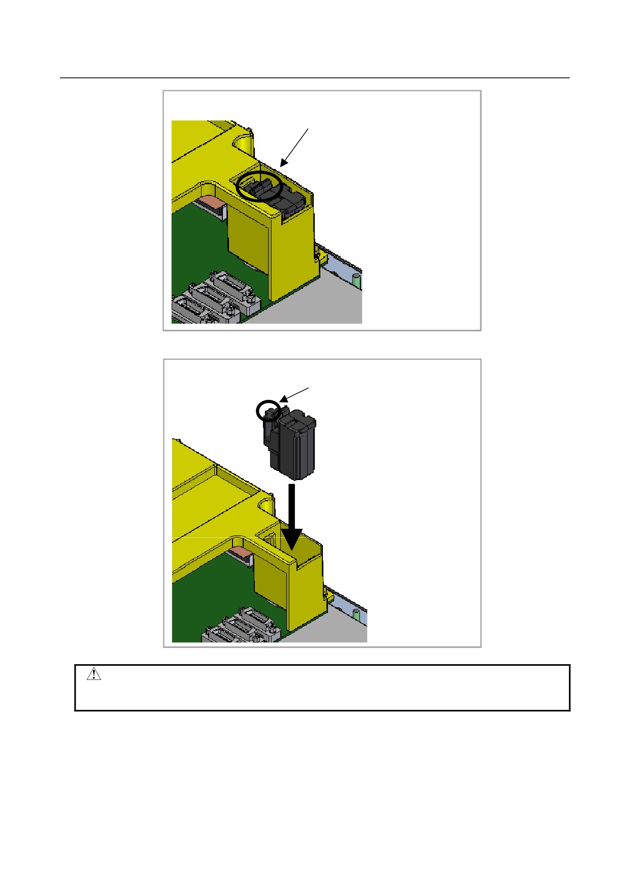
(2) Extract the old battery unit from the lower right of the rear of the CNC unit. (Hold the latch of the
battery unit, and extract the unit upward while releasing the claw from the case.)
- 756 -
B-64304EN/02
MAINTENANCE
1.ROUTINE MAINTENANCE
Extract the unit while holding this portion.
(3) Mount the new battery unit. (Push the battery unit in until the claw is latched into the case.) Ensure
that the latch is engaged securely.
Push the unit in until the claw is
latched into the case.
WARNING
Using other than the recommended battery may result in the battery exploding.
Replace the battery only with the specified battery (A02B-0309-K102).
- 757 -
1.ROUTINE MAINTENANCE
MAINTENANCE
B-64304EN/02
CAUTION
Steps (1) to (3) should be completed within 30 minutes. Do not leave the
control unit without a battery for any longer than the specified period. Otherwise,
the contents of memory may be lost.
If steps (1) to (3) may not be completed within 30 minutes, save all contents of
the SRAM memory to the memory card beforehand. Thus, if the contents of the
SRAM memory are lost, the contents can be restored easily.
See Chapter 5, "INPUT AND OUTPUT OF DATA" or Appendix C, "BOOT
SYSTEM" of maintenance manual (B-64305EN) for explanations about how to
save the contents of the SRAM memory.
When discarding a battery, observe the applicable ordinances or other rules of your local government.
In addition, cover the exposed pins with tape or other insulation materials to prevent a short circuit before
discarding the battery.
When a lithium battery is used (Stand-alone type)
- Replacement procedure
If a lithium battery is used, have A02B-0200-K102 (FANUC internal code: A98L-0031-0012) handy.
1
Turn the CNC on. About 30 seconds later, turn the CNC off.
2
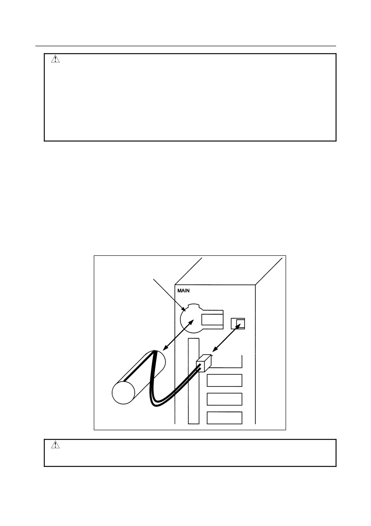
Remove the battery from the top area of the CNC unit.
Disconnect the connector first. Then, remove the battery from the battery case. The connector is
not latched. Simply pulling the cable detaches the connector.
The battery case is provided in the top area of the face plate of the main board.
3
Replace the battery, then connect the connector.
Battery case
Lithium battery
A02B-0200-K102
Connector
WARNING
The incorrect mounting of the battery may cause an explosion. Avoid using any
battery other than the one specified here (A02B-0200-K102).
- 758 -
B-64304EN/02
MAINTENANCE
1.ROUTINE MAINTENANCE
CAUTION
Complete steps 1 to 3 within 30 minutes.
If the battery is left removed for a long time, the SRAM would lose the contents.
If there is a danger that the replacement cannot be completed within 30 minutes,
save the whole contents of the SRAM to a memory card. The contents of the
memory can be easily restored with the memory card in case the memory loses
the contents.
See Chapter 5, "INPUT AND OUTPUT OF DATA" or Appendix C, "BOOT
SYSTEM" of maintenance manual (B-64305EN) for explanations about how to
save the contents of the SRAM memory.
Discard the dead battery, observing appropriate municipal rules and regulations. When discarding the
battery, insulate the terminal with a tape so that no short-circuit would occur.
When alkaline dray cells (size D) are used
-
Replacing the battery
(1) Prepare two new alkaline dry cells (size D).
(2) Turn on the power of the control unit.
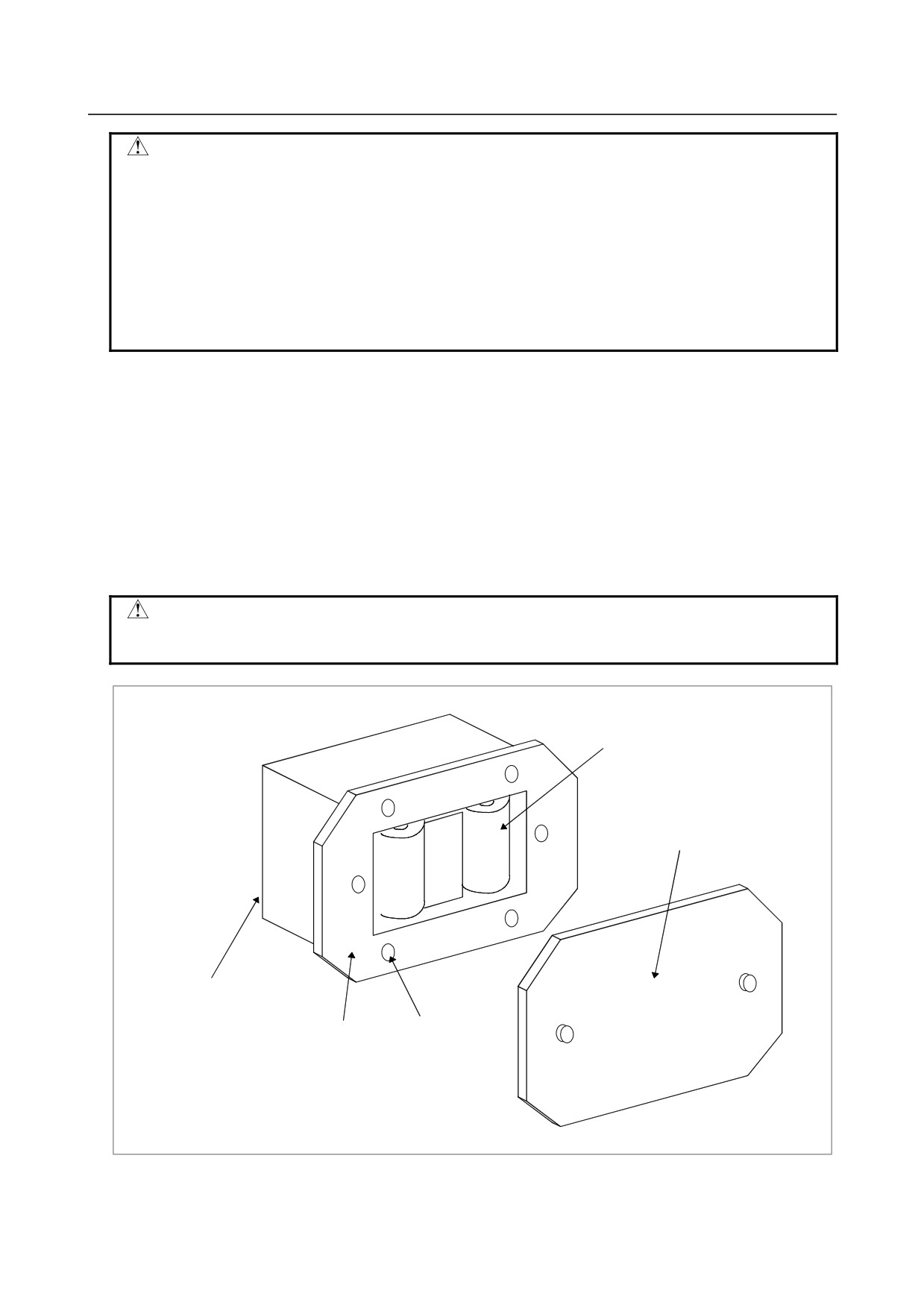
(3) Remove the battery case cover.
(4) Replace the batteries, paying careful attention to their orientation.
(5) Replace the battery case cover.
CAUTION
To replace the battery when the power is off, follow the same procedure as that
for the replacement of a lithium battery, described above.
Dry cell × 2
Cover
Connection terminal
on the rear
Battery case
Mounting hole × 4
- 759 -

1.ROUTINE MAINTENANCE
MAINTENANCE
B-64304EN/02
1.3.2
Battery for Absolute Pulsecoders
• When the voltage of the batteries for absolute Pulsecoders becomes low, alarm 307 or 306 occurs,
with the following indication in the CNC state display at the bottom of the CNC screen.
Alarm 307 (alarm indicating the voltage of the battery becomes low) :
The indication "APC" blinks in reversed display.
Alarm 306 (battery zero alarm) :
The indication "ALM" blinks in reversed display.
• When alarm 307 (alarm indicating the voltage of the battery becomes low) occurs, replace the
battery as soon as possible. In general, the battery should be replaced within one or two weeks,
however, this depends on the number of Pulsecoders used.
• When alarm 306 (battery zero alarm) occurs, Pulsecoders are reset to the initial state, in which
absolute positions are not held. Alarm 300 (reference position return request alarm) also occurs,
indicating that reference position return is required.
• In general, replace the batteries periodically within the service life listed below.
- A06B-6050-K061 or D-size alkaline dry cells (LR20) :
Two years (for each six-axis configuration)
- A06B-6073-K001 :
Two years (for each three-axis configuration)
- A06B-6114-K504 :
One year (for each three-axis configuration)
NOTE
The above values indicate the estimated service life of batteries used with
FANUC absolute Pulsecoders. The actual battery service life depends on the
machine configuration based on, for example, detector types. For details,
contact the machine tool builder.
-
Replacing batteries
To prevent absolute position information in absolute Pulsecoders from being lost, turn on the machine
power before replacing the battery. The replacement procedure is described below.
(1) Ensure that the power to the servo amplifier is turned on.
(2) Ensure that the machine is in the emergency stop state (the motor is inactive).
(3) Ensure that the DC link charge LED of the servo amplifier is off.
(4) Detach the old batteries and attach new ones.
The replacement of the batteries in a separate battery case and the replacement of the battery built into the
servo amplifier are described below in detail.
- 760 -
B-64304EN/02
MAINTENANCE
1.ROUTINE MAINTENANCE
WARNING
- The absolute Pulsecoder of each of the Įi/Įi S series servo motors and the ȕi S
series servo motors (ȕi S0.4 to ȕi S22) has a built-in backup capacitor.
Therefore, even when the power to the servo amplifier is off and the batteries
are replaced, reference position return is not required if the replacement
completes within less than 10 minutes. Turn the power on and replace the
batteries if the replacement will take 10 minutes or more.
- To prevent electric shock, be careful not to touch metal parts in the power
magnetics cabinet when replacing the batteries.
- Because the servo amplifier uses a large-capacitance electrolytic capacitor
internally, the servo amplifier remains charged for a while even after the power is
turned off. Before touching the servo amplifier for maintenance or other
purposes, ensure your safety by measuring the residual voltage in the DC link
with a tester and confirming that the charge indication LED (red) is off.
- Be sure to replace the batteries with specified ones. Pay attention to the battery
polarity. If a wrong type of battery is used or a battery is installed with incorrect
polarity, the battery may overheat, blow out, or catch fire, or the absolute
position information in the absolute Pulsecoders may be lost.
- Ensure that the battery connector is inserted in the correct position.
-
Replacing the Batteries in a Separate Battery Case
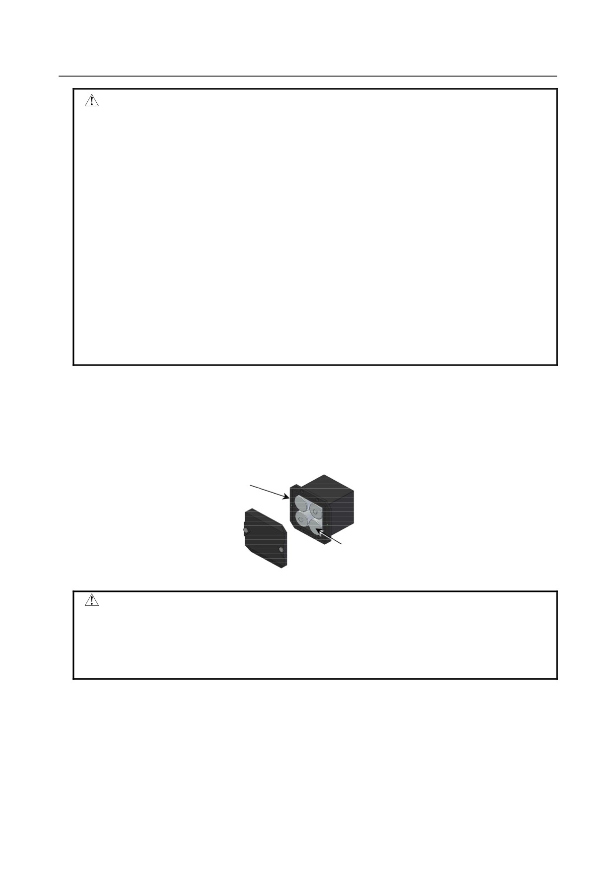
Use the following procedure to replace the batteries in the battery case.
(1) Loosen the screws on the battery case and detach the cover.
(2) Replace the batteries in the case (pay attention to the polarity).
(3) Attach the cover to the battery case.
Battery case (with a cover)
A06B-6050-K060
Batteries
Four A06B-6050-K061 batteries or
D-size alkaline dry cells
CAUTION
- Four D-size alkaline dry cells (LR20) that are commercially available can be
used as batteries. A set of four A06B-6050-K061 batteries is optionally available
from FANUC.
- Replace all the four batteries with new ones. If old and new batteries are mixed,
the absolute position information in the absolute Pulsecoders may be lost.
-
Replacing the Battery Built into the Servo Amplifier
Use the following procedure to replace the special lithium battery.
(1) Detach the battery cover.
(2) Replace the special lithium battery.
(3) Attach the battery cover.
- 761 -
1.ROUTINE MAINTENANCE
MAINTENANCE
B-64304EN/02
CAUTION
- Purchase the battery from FANUC because it is not commercially available. It is
therefore recommended that you have a backup battery.
- When the built-in battery is used, do not connect BATL (B3) of connector
CXA2A/CXA2B. Also, do not connect two or more batteries to the same BATL
(B3) line. These connections are dangerous because battery output voltages
may be short-circuited, causing the batteries to overheat.
- Install the battery in the servo amplifier in a direction that allows slack in the
cable. If the battery cable is under tension, a bad connection may occur.
- If the +6 V pin and 0 V pin are short-circuited, the battery may overheat, blow
out, or catch fire, or the absolute position information in the absolute
Pulsecoders may be lost.
- When inserting the connector, align it to the connector pins.
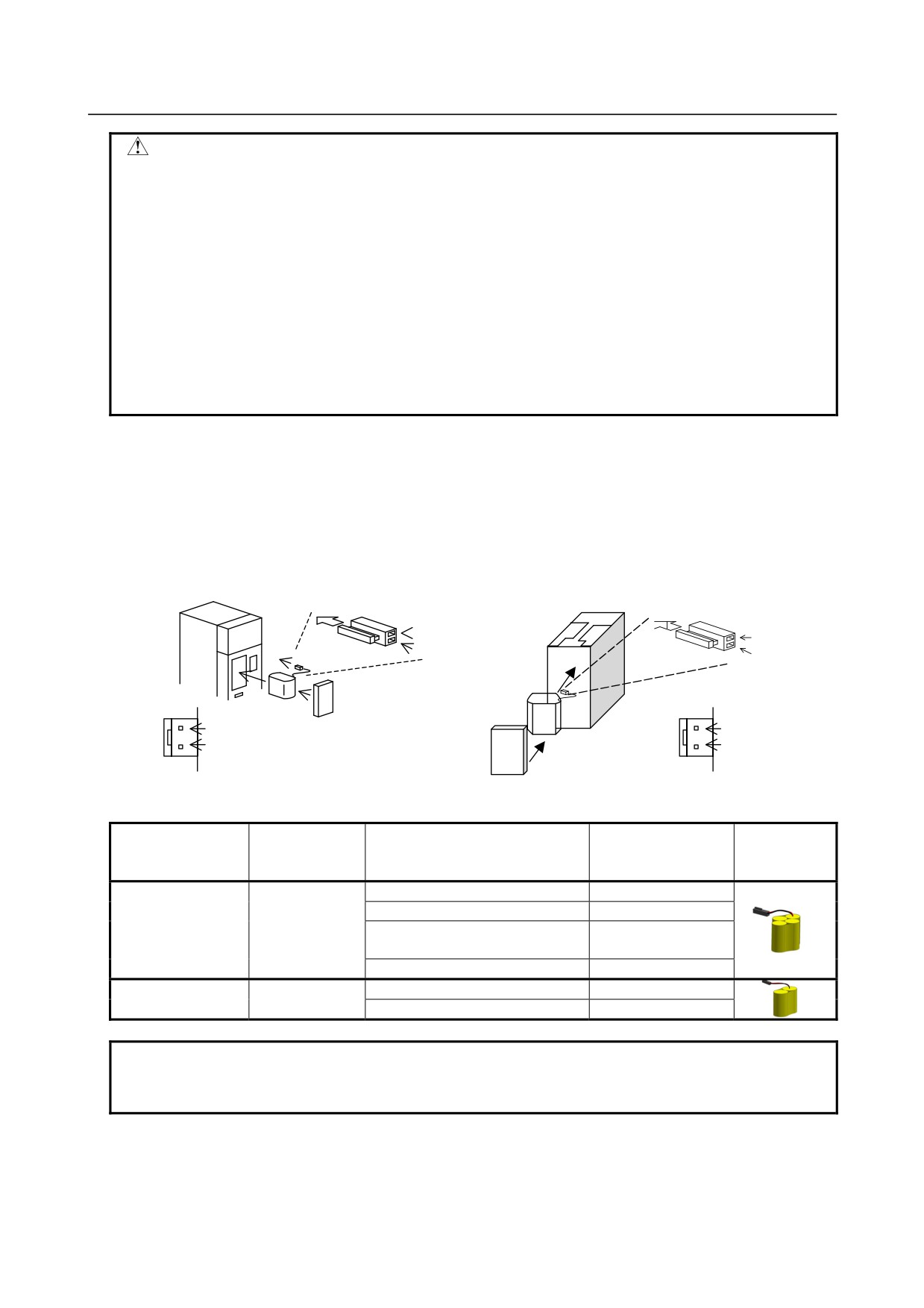
[Connecting the battery]
The battery for the ȕiSV4 and ȕiSV20 series amplifiers is mounted in the battery case on the underside of
each of the amplifiers.
The battery for the other ȕi series amplifiers and the Įi series amplifiers is mounted at the front of each of
the amplifiers.
[αi series][βi series βi SV40, βi SV80, βi SVSP]
[βi series βi SV4, βi SV20]
Insertion direction
Cable side
Insertion direction
Cable side
Red: +6 V
Red: +6 V
Connector
Black: 0 V
Connector
Black: 0 V
CX5X
CX5X
Battery
+6 V
Battery case
+6 V
0 V
0 V
Battery
Battery case
[Battery sets and outlines]
Battery case
Battery ordering
Manufacturer
Applicable servo amplifier
ordering drawing
Outline
drawing number
model number
number
BR-2/3AGCT4A
αi series
60/90 mm width
A06B-6114-K505
(Panasonic)
αi series
150/300 mm width
A06B-6114-K506
A06B-6114-K504
βi series βi SV
(Note)
A06B-6114-K505
(two-axis model)
βi series βi SVSP
A06B-6114-K506
BR-AGCF2W
βi series βiSV4, βiSV20
A06B-6093-K002
A06B-6093-K001
(Panasonic)
βi series βiSV40, βiSV80
A06B-6093-K002
NOTE
When an old type BR-CCF2TH battery is used, order a battery case that
accommodates battery A06B-6114-K504.
-
Used batteries
Old batteries should be disposed as "INDUSTRIAL WASTES" according to the regulations of the
country or autonomy where your machine has been installed.
- 762 -
APPENDIX
B-64304EN/02
APPENDIX
A.PARAMETERS
A PARAMETERS
This manual describes all parameters indicated in this manual.
For those parameters that are not indicated in this manual and other parameters, refer to the parameter
manual.
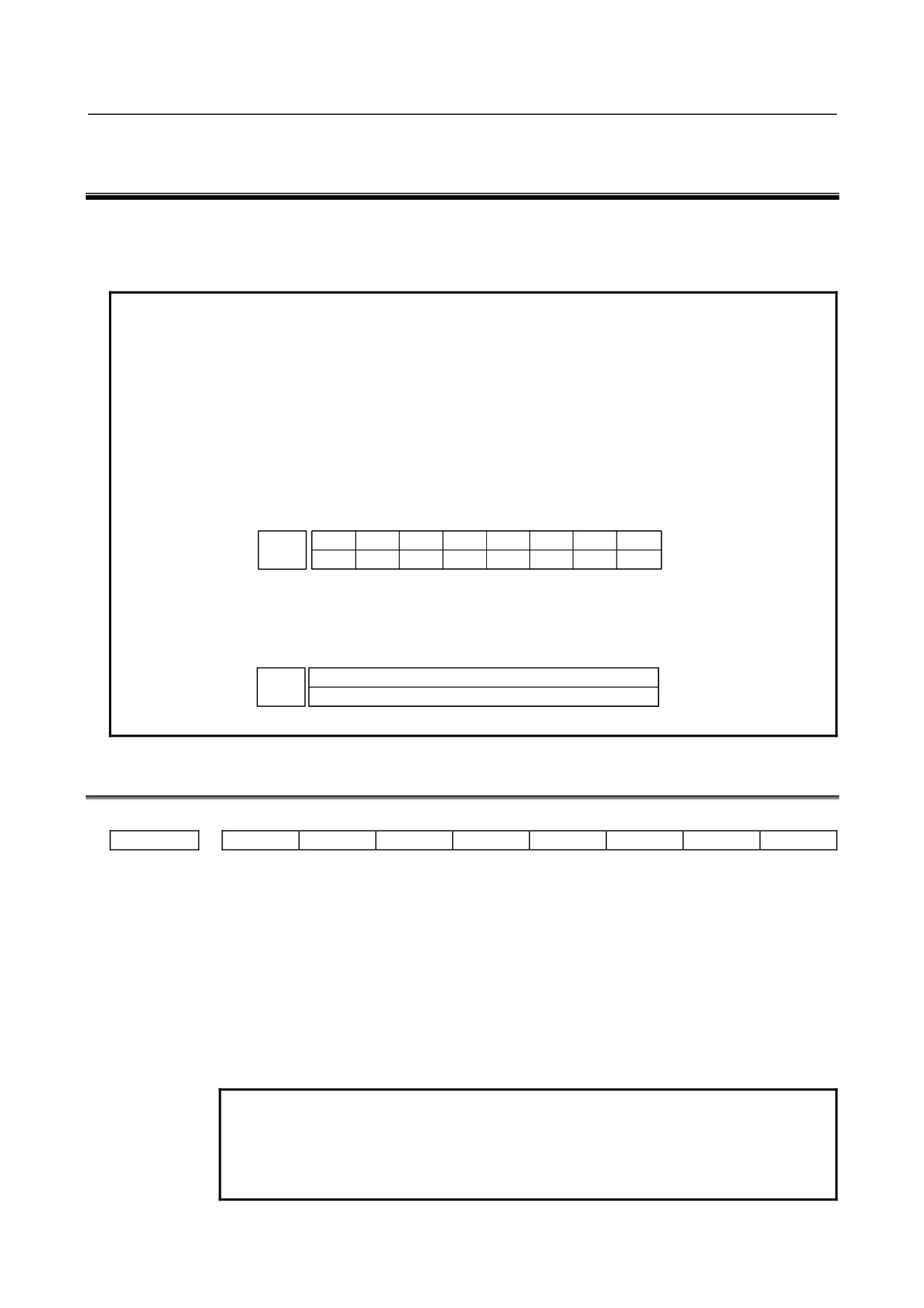
NOTE
A parameter that is valid with only one of the path control types for the lathe
system (T series) and machining center system (M series) is indicated in the
upper or lower row as described below. A blank represents an unusable
parameter.
[Example 1]
The parameter HTG is common to the T series and M series, and RTV and ROC
are parameters used with the T series only.
#7
#6
#5
#4
#3
#2
#1
#0
RTV
HTG
ROC
T series
1403
HTG
M series
[Example 2]
The following parameter is used with the M series only:
T series
1411
Cutting feedrate
M series
A.1 DESCRIPTION OF PARAMETERS
#7
#6
#5
#4
#3
#2
#1
#0
0000
ISO
TVC
[Input type] Setting input
[Data type] Bit path
#0 TVC TV check
0: Not performed
1: Performed
#1 ISO Code used for data output
0: EIA code
1: ISO code
NOTE
1 The I/O setting of a memory card is made by bit 0 (ISO) of
parameter No. 0139.
2 The I/O setting of data server is made by bit 0 (ISO) of parameter
No. 0908.
- 765 -
A.PARAMETERS
APPENDIX
B-64304EN/02
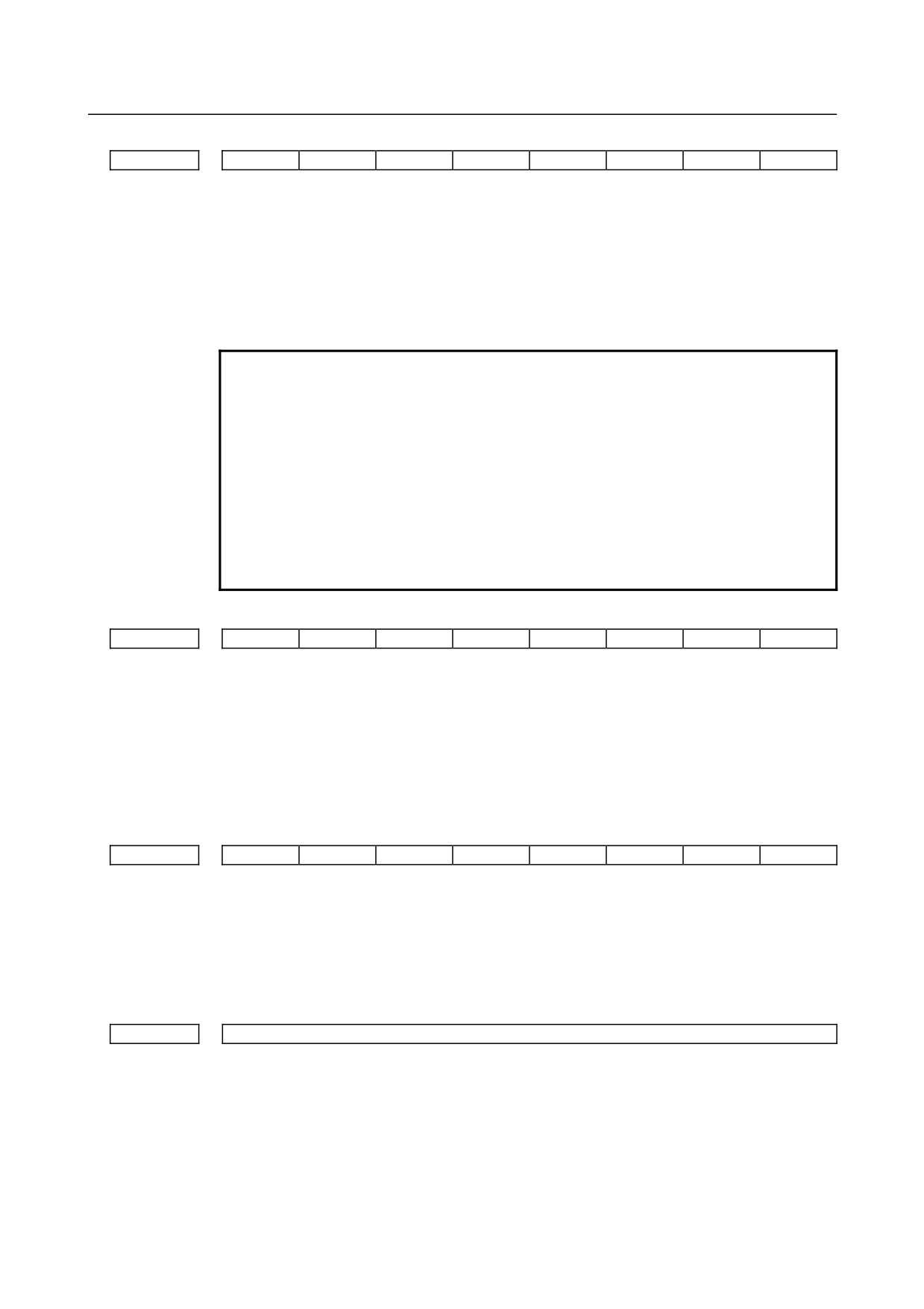
#7
#6
#5
#4
#3
#2
#1
#0
0001
FCV
[Input type] Setting input
[Data type] Bit path
#1 FCV Program format
0: Series 0 standard format
(This format is compliant with the Series 0i-C.)
1: Series 10/11 format
NOTE
1 Programs created in the Series 10/11 program format can be used
for operation on the following functions:
1 Subprogram call M98,M198
2 Thread cutting with equal leads G32 (T series)
3 Canned cycle G90, G92, G94 (T series)
4 Multiple repetitive canned cycle G71 to G76 (T series)
5 Drilling canned cycle G80 to G89 (T series)
G73, G74, G76, G80 to G89(M series)
2 When the program format used in the Series 10/11 is used for this
CNC, some limits may add. Refer to the OPERATOR’S MANUAL.
#7
#6
#5
#4
#3
#2
#1
#0
0010
PRM
[Input type] Setting input
[Data type] Bit path
#1 PRM Whether the parameter whose setting is 0 is output or not:
0: It is selected with soft key [ALL] or [NON-0].
1: It is not selected with soft key [ALL] or [NON-0]. The parameter whose setting is 0
is not output.
#7
#6
#5
#4
#3
#2
#1
#0
0012
MIRx
[Input type] Setting input
[Data type] Bit axis
#0 MIRx Mirror image for each axis
0: Mirror image is off. (Normal)
1: Mirror image is on. (Mirror)
0020
I/O CHANNEL : Input/output device selection, or interface number for a foreground input device
[Input type] Setting input
[Data type] Byte
[Valid data range] 0 to 9
The CNC has the following interfaces for transferring data to and from an external
input/output device and the host computer:
• Input/output device interface (RS-232-C serial ports 1 and 2)
• Memory card interface
- 766 -
B-64304EN/02
APPENDIX
A.PARAMETERS
• Data server interface
• Embedded Ethernet interface
By setting bit
0 (IO4) of parameter No. 0110, data input/output can be controlled
separately. When IO4 is not set, data input/output is performed using the channel set in
parameter No. 0020. When IO4 is set, a channel can be assigned to each of foreground
input, foreground output, background input, and background output.
In these parameters, specify the interface connected to each input/output device to and
from which data is to be transferred. See the table below for these settings.
To execute the DNC operation or M198 command with FOCAS2/Ethernet, set this
parameter to 6.
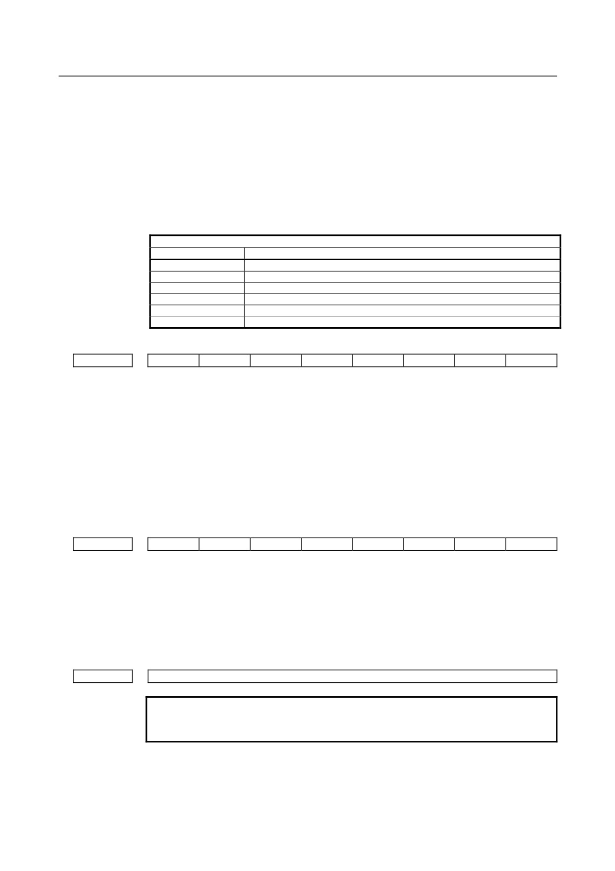
Correspondence between settings and input/output devices
Setting
Description
0,1
RS-232-C serial port 1
2
RS-232-C serial port 2
4
Memory card interface
5
Data server interface
6
Execution of the DNC operation or M198 command with FOCAS2/Ethernet
9
Embedded Ethernet interface
#7
#6
#5
#4
#3
#2
#1
#0
0100
NCR
CTV
[Input type] Setting input
[Data type] Bit
#1 CTV Character counting for TV check in the comment section of a program.
0: Performed
1: Not performed
#3 NCR Output of the end of block (EOB) in ISO code
0: LF, CR, CR are output.
1: Only LF is output.
#7
#6
#5
#4
#3
#2
#1
#0
0138
MNC
[Input type] Parameter input
[Data type] Bit
#7 MNC DNC operation from the memory card and external device subprogram call from the
memory card are:
0: Not performed.
1: Performed.
0980
Machine group number to which each path belongs
NOTE
When this parameter is set, the power must be turned off before
operation is continued.
[Input type] Parameter input
[Data type] Byte path
[Valid data range] 1
Set the machine group number to which each path belongs.
- 767 -
A.PARAMETERS
APPENDIX
B-64304EN/02
For the 0i-D/0i Mate-D, be sure to set this parameter to 1.
NOTE
If this parameter is set to 0, a setting of 1 is assumed.
0981
Absolute path number to which each axis belongs
NOTE
When this parameter is set, the power must be turned off before
operation is continued.
[Input type] Parameter input
[Data type] Byte axis
[Valid data range] 1, 2
Set the path to which each axis belongs.
NOTE
1 When 0 is set for all axes, the parameter is automatically set
according to the number of controlled axes of each path.
2 When the setting falls outside the range, the axis is assumed to
belong to the first path.
0982
Absolute path number to which each spindle belongs
NOTE
When this parameter is set, the power must be turned off before
operation is continued.
[Input type] Parameter input
[Data type] Byte spindle
[Valid data range] 1, 2
Set the path to which each spindle belongs.
NOTE
1 When 0 is set for all axes, the parameter is automatically set
according to the number of controlled axes of each path.
2 When the setting falls outside the range, the axis is assumed to
belong to the first path.
3 When spindle control with servo motor is enabled, the servo motor
used as the spindle controlled axis is treated as a spindle.
Therefore, it is necessary to set the path to which the axis subject
to spindle control with servo motor.
0983
Path control type of each path
NOTE
1 When this parameter is set, the power must be turned off before
operation is continued.
2 For the 0i -D/0i Mate-D, this parameter does not need to be set
because it is set automatically.
- 768 -
B-64304EN/02
APPENDIX
A.PARAMETERS
[Input type] Parameter input
[Data type] Byte path
[Valid data range] 0 to 1
Set the path control type of each path.
The following two path control types are available:
T series (lathe system)
:
0
M series (machining system):
1
#7
#6
#5
#4
#3
#2
#1
#0
1001
INM
[Input type] Parameter input
[Data type] Bit path
NOTE
When this parameter is set, the power must be turned off before
operation is continued.
#0 INM Least command increment on the linear axis
0: In mm (metric system machine)
1: In inches (inch system machine)
#7
#6
#5
#4
#3
#2
#1
#0
1002
IDG
XIK
AZR
JAX
[Input type] Parameter input
[Data type] Bit path
#0 JAX Number of axes controlled simultaneously in jog feed, manual rapid traverse and manual
reference position return:
0:
1 axis
1:
3 axes
#3 AZR When no reference position is set, the G28 command causes:
0: Reference position return using deceleration dogs
(as during manual reference
position return) to be executed.
1: Alarm (PS0304) “G28 was specified when no reference position is set” to be
displayed.
NOTE
When reference position return without dogs is specified, (when bit
1 (DLZ) of parameter No.1005 is set to 1) the G28 command
specified before a reference position is set causes an alarm
PS0304 to be issued, regardless of the setting of AZR.
#4 XIK When LRP, bit 1 of parameter No.1401, is set to 0, namely, when positioning is
performed using non-linear type positioning, if an interlock is applied to the machine
along one of axes in positioning,
0: The machine stops moving along the axis for which the interlock is applied and
continues to move along the other axes.
1: The machine stops moving along all the axes.
- 769 -
A.PARAMETERS
APPENDIX
B-64304EN/02
#7 IDG When the reference position is set without dogs, automatic setting of the IDGx parameter
(bit 0 of parameter No.1012) to prevent the reference position from being set again is:
0: Not performed.
1: Performed.
#7
#6
#5
#4
#3
#2
#1
#0
1004
IPR
[Input type] Parameter input
[Data type] Bit path
#7 IPR Whether the least input increment for each axis is set to a value 10 times as large as the
least command increment is specified, in increment systems of IS-B or IS-C at setting
mm.
0: The least input increment is not set to a value 10 times as large as the least command
increment.
1: The least input increment is set to a value 10 times as large as the least command
increment.
If IPR is set to 1, the least input increment is set as follows:
Input increment
Least input increment
IS-B
0.01 mm, 0.01 deg, or 0.0001 inch
IS-C
0.001 mm, 0.001 deg, or 0.00001 inch
NOTE
For IS-A, the least input increment cannot be set to a value 10
times as large as the least command increment.
The least input increment is not multiplied by 10 also when the
calculator-type decimal point input (bit 0 (DPI) of parameter No.
3401) is used.
#7
#6
#5
#4
#3
#2
#1
#0
1005
EDMx
EDPx
ZRNx
[Input type] Parameter input
[Data type] Bit axis
#0 ZRNx If a move command other than G28 is specified by automatic operation when no
reference position return is performed yet after the power is turned on:
0: The alarm (PS0224) "PERFORM REFERENCE POSITION RETURN." is issued.
1: Operation is performed without issuing an alarm.
NOTE
1 The state in which a reference position has not been established
refers to the following state:
- When an absolute position detector is not used and reference
position return has not been performed even once after power-up
- When an absolute position detector is used and the association of
the machine position with the position detected with the absolute
position detector has not been completed (See the description of
bit 4 (APZx) of parameter No. 1815.)
2 When the Cs axis coordinates are to be set up, set ZRN to 0.
- 770 -
B-64304EN/02
APPENDIX
A.PARAMETERS
#4 EDPx In cutting feed, an external deceleration signal in the + direction for each axis is:
0: Invalid
1: Valid
NOTE
Be sure to set "1" to this parameter if bit 5 (EDR) of parameter
No.1405 is set to 0 when positioning linear interpolation type is used.
#5 EDMx In cutting feed, an external deceleration signal in the - direction for each axis is:
0: Invalid
1: Valid
NOTE
Be sure to set "1" to this parameter if bit 5 (EDR) of parameter
No.1405 is set to 0 when positioning linear interpolation type is used.
#7
#6
#5
#4
#3
#2
#1
#0
1006
ZMIx
DIAx
ROSx
ROTx
[Input type] Parameter input
[Data type] Bit axis
NOTE
When at least one of these parameters is set, the power must be
turned off before operation is continued.
#0 ROTx
Setting linear or rotation axis.
#1
ROSx
Setting linear or rotation axis.
ROSx
ROTx
Meaning
0
0
Linear axis
(1) Inch/metric conversion is done.
(2) All coordinate values are linear axis type. (Is not rounded in 0 to
360°)
(3) Stored pitch error compensation is linear axis type (Refer to
parameter No.3624)
0
1
Rotation axis (A type)
(1) Inch/metric conversion is not done.
Machine coordinate values are rounded in 0 to 360°. Absolute
coordinate values are rounded or not rounded by parameter
No.1008#0(ROAx) and #2(RRLx).
(2) Stored pitch error compensation is the rotation type. (Refer to
parameter No.3624)
(3) Automatic reference position return (G28, G30) is done in the
reference position return direction and the move amount does not
exceed one rotation.
1
1
Rotation axis (B type)
(1) Inch/metric conversion, absolute coordinate values and relative
coordinate values are not done.
(2) Machine coordinate values, absolute coordinate values and relative
coordinate values are linear axis type. (Is not rounded in 0 to 360°).
(3) Stored pitch error compensation is linear axis type (Refer to
parameter No.3624)
(4) Cannot be used with the rotation axis roll over function and the
index table indexing function (M series)
- 771 -
A.PARAMETERS
APPENDIX
B-64304EN/02
ROSx
ROTx
Meaning
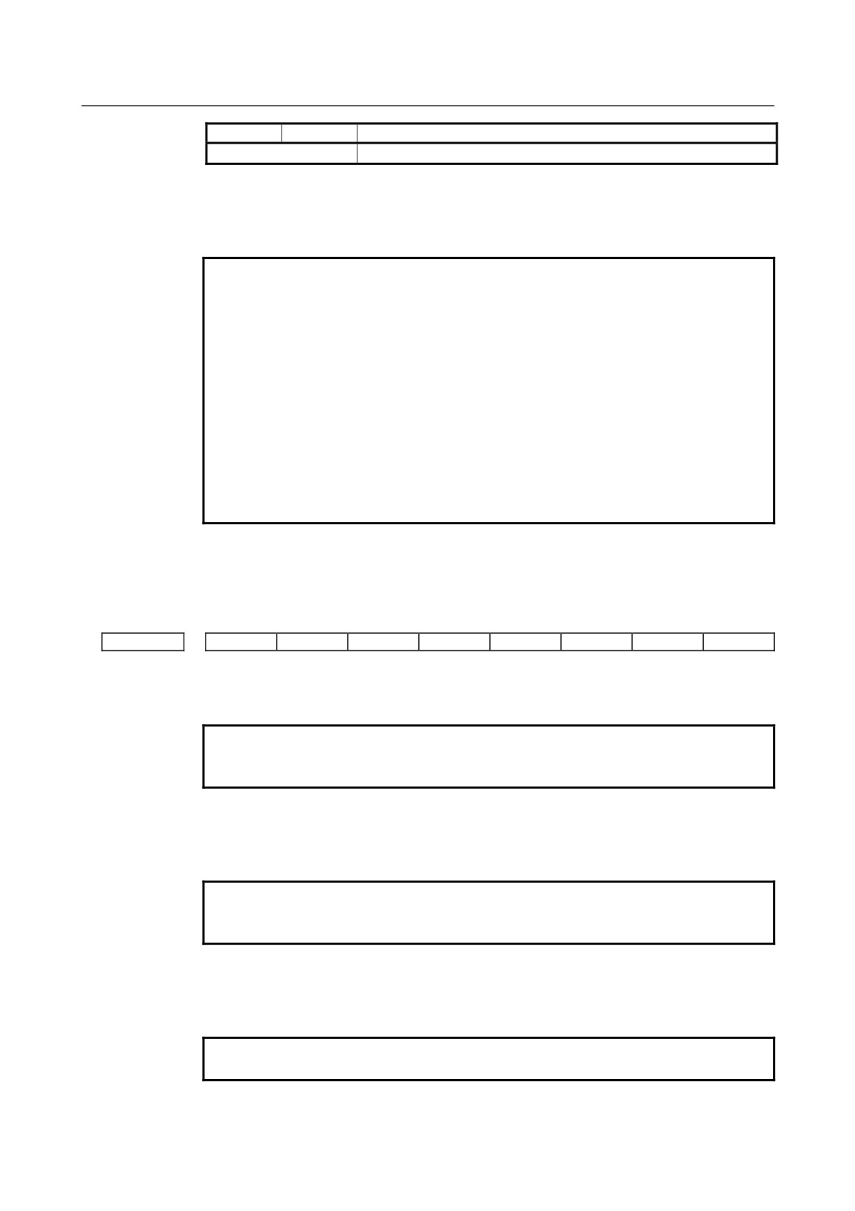
Except for the above.
Setting is invalid (unused)
#3 DIAx The move command for each axis is based on:
0: Radius specification
1: Diameter specification
NOTE
For the FS0i-C, one of the following changes is required besides
setting bit 3 (DIAx) of parameter No. 1006 so that the axis based
on diameter specification achieves the specified amount of
movement.
• Halve the command multiplication (the detection unit is not
changed).
• Halve the detection unit and double the flexible feed gear
(DMR).
For the FS0i-D, only if bit 3 (DIAx) of parameter No. 1006 is set,
the CNC halves the specified pulse. Accordingly, the above
changes are not required (when the detection unit is not changed).
To halve the detection unit, double both CMR and DMR.
#5 ZMIx The direction of manual reference position return is:
0:
+ direction
1:
- direction
#7
#6
#5
#4
#3
#2
#1
#0
1008
RRLx
RABx
ROAx
[Input type] Parameter input
[Data type] Bit axis
NOTE
When at least one of these parameters is set, the power must be
turned off before operation is continued.
#0 ROAx The roll-over function of a rotation axis is
0: Invalid
1: Valid
NOTE
ROAx specifies the function only for a rotation axis (for which bit 0
(ROTx) of parameter No.1006, is set to 1)
#1 RABx In the absolute commands, the axis rotates in the direction
0: In which the distance to the target is shorter.
1: Specified by the sign of command value.
NOTE
RABx is valid only when ROAx is 1.
- 772 -
B-64304EN/02
APPENDIX
A.PARAMETERS
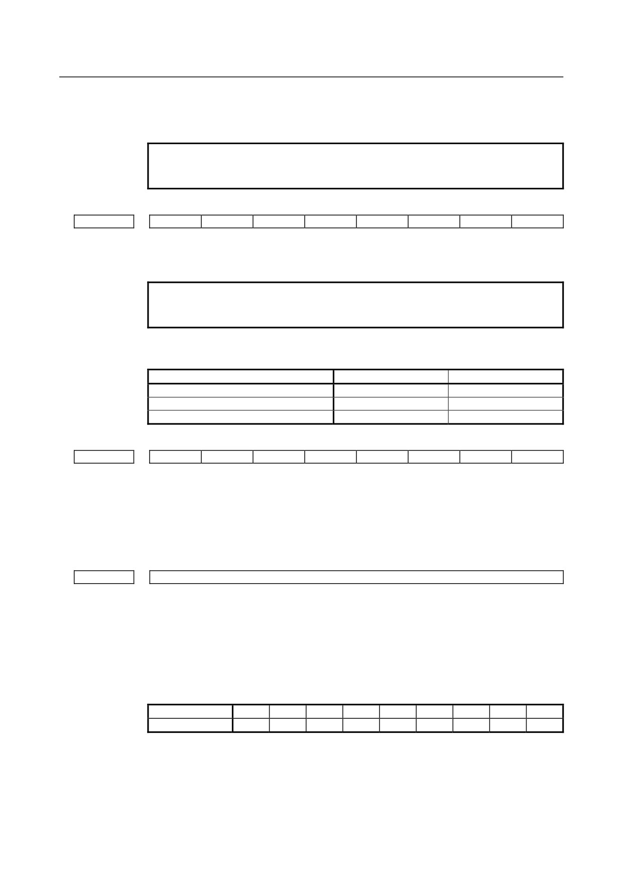
#2 RRLx Relative coordinates are
0: Not rounded by the amount of the shift per one rotation
1: Rounded by the amount of the shift per one rotation
NOTE
1 RRLx is valid only when ROAx is 1.
2 Assign the amount of the shift per one rotation in parameter No.1260.
#7
#6
#5
#4
#3
#2
#1
#0
1013
ISCx
ISAx
[Input type] Parameter input
[Data type] Bit axis
NOTE
When at least one of these parameters is set, the power must be
turned off before operation is continued.
#0 ISAx
#1 ISCx Increment system of each axis
Increment system
#1 ISCx
#0 ISAx
IS-A
0
1
IS-B
0
0
IS-C
1
0
#7
#6
#5
#4
#3
#2
#1
#0
1015
DWT
[Input type] Parameter input
[Data type] Bit path
#7 DWT When time for dwell per second is specified by P, the increment system:
0: Depends on the increment system
1: Does not depend on the increment system (1 ms)
1020
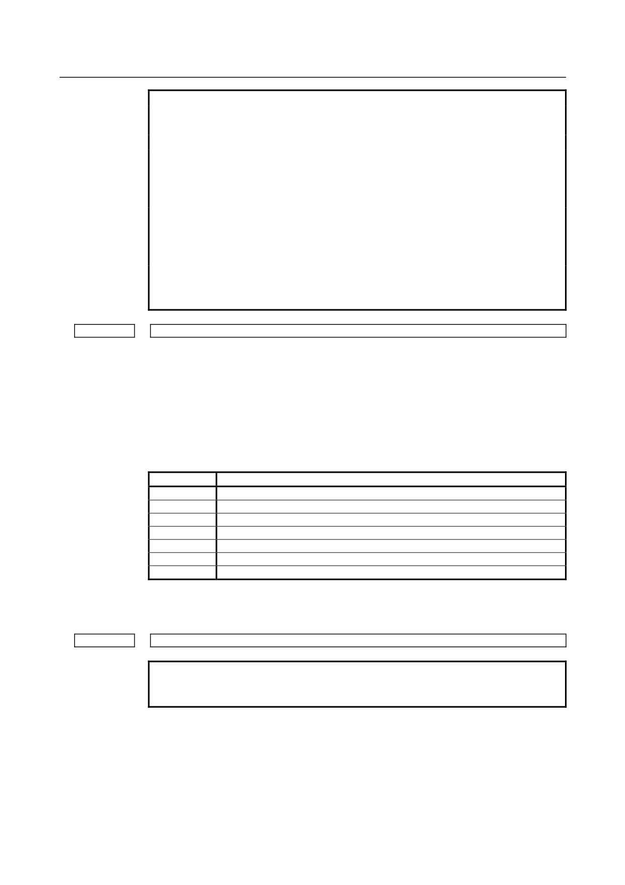
Program axis name for each axis
[Input type] Parameter input
[Data type] Byte axis
[Valid data range] 65 to 67,85 to 90
An axis name (parameter No. 1020) can be arbitrarily selected from 'A', 'B', 'C', 'U', 'V',
'W', 'X', 'Y', and 'Z'. (When G code system A is used with the T series, however, 'U', 'V',
and 'W' are not selectable.)
(Tip) ASCII code
Axis name
X
Y
Z
A
B
C
U
V
W
Setting
88
89
90
65
66
67
85
86
87
For the axes with axis names of 'X', 'Y', 'Z', and 'C' in G code system A of the T series, the
'U', 'V', 'W', and 'H' commands are the incremental commands of these axes.
- 773 -
A.PARAMETERS
APPENDIX
B-64304EN/02
NOTE
1 When G code system A is used in the T series, U, V, or W cannot
be used as an axis name.
2 The same axis name cannot be set for multiple axes.
3 When the second auxiliary function is provided (when bit 2 (BCD)
of parameter No. 8132 is 1), if the address (parameter No. 3460)
that specifies the second auxiliary function is used as an axis
name, the second auxiliary function is disabled.
4 When address C or A is used during chamfering/corner rounding or
direct drawing dimension programming (when bit 4 (CCR) of
parameter No. 3405 is 1) in the T series, address C or A cannot be
used as an axis name.
5 When the multiple repetitive turning canned cycle (T series) is
used, only 'X', 'Y', and 'Z' can be used for the address of the target
axis.
1022
Setting of each axis in the basic coordinate system
[Input type] Parameter input
[Data type] Byte axis
[Valid data range] 0 to 7
To determine a plane for circular interpolation, tool radius/tool nose radius compensation,
and so forth (G17: Xp-Yp plane, G18: Zp-Xp plane, G19: Yp-Zp plane), specify which of
the basic three axes (X, Y, and Z) is used for each control axis, or a parallel axis of which
basic axis is used for each control axis.
A basic axis (X, Y, or Z) can be specified only for one control axis.
Two or more control axes can be set as parallel axes for the same basic axis.
Setting
Meaning
0
Rotation axis (Neither the basic three axes nor a parallel axis )
1
X axis of the basic three axes
2
Y axis of the basic three axes
3
Z axis of the basic three axes
5
Axis parallel to the X axis
6
Axis parallel to the Y axis
7
Axis parallel to the Z axis
In general, the increment system and diameter/radius specification of an axis set as a
parallel axis are to be set in the same way as for the basic three axes.
1023
Number of the servo axis for each axis
NOTE
When this parameter is set, the power must be turned off before
operation is continued.
[Input type] Parameter input
[Data type] Byte axis
[Valid data range] 0 to Number of controlled axes
Set the servo axis for each control axis.
Usually set to same number as the control axis number.
The control axis number is the order number that is used for setting the axis-type
parameters or axis-type machine signals
- 774 -
B-64304EN/02
APPENDIX
A.PARAMETERS
• With an axis for which Cs contour control/spindle positioning is to be performed, set
-(spindle number) as the servo axis number.
Example)
When exercising Cs contour control on the fourth controlled axis by using the first
spindle, set -1.
• For tandem controlled axes or electronic gear box (EGB) controlled axes, two axes
need to be specified as one pair. So, make a setting as described below.
Tandem axis:
For a master axis, set an odd (1, 3, 5, 7, ...) servo axis number. For a slave axis to be
paired, set a value obtained by adding 1 to the value set for the master axis.
EGB axis:
For a slave axis, set an odd (1, 3, 5, 7, ...) servo axis number. For a dummy axis to
be paired, set a value obtained by adding 1 to the value set for the slave axis.
1031
Reference axis
[Input type] Parameter input
[Data type] Byte path
[Valid data range] 1 to Number of controlled axes
The unit of some parameters common to all axes such as those for dry run feedrate and
one-digit F code feed may vary according to the increment system. An increment system
can be selected by a parameter on an axis-by-axis basis. So, the unit of those parameters
is to match the increment system of a reference axis. Set which axis to use as a reference
axis.
Among the basic three axes, the axis with the finest increment system is generally
selected as a reference axis.
#7
#6
#5
#4
#3
#2
#1
#0
1201
ZCL
ZPR
[Input type] Parameter input
[Data type] Bit path
#0 ZPR Automatic setting of a coordinate system when the manual reference position return is
performed
0: Not set automatically
1: Set automatically
NOTE
ZPR is valid when the workpiece coordinate system is not used
(when bit 0 (NWZ) of parameter No. 8136 is 1). When the
workpiece coordinate system is used, the workpiece coordinate
system is established based on the workpiece origin offset
(parameters No. 1220 to 1226) during a manual reference position
return, regardless of the setting of this parameter.
#2 ZCL Local coordinate system when the manual reference position return is performed
0: The local coordinate system is not canceled.
1: The local coordinate system is canceled.
- 775 -
A.PARAMETERS
APPENDIX
B-64304EN/02
NOTE
ZCL is valid when the workpiece coordinate system is used (when
bit 0 (NWZ) of parameter No. 8136 is 0). To use the local
coordinate system (G52), set bit 0 (NWZ) of parameter No. 8136 to
0.
#7
#6
#5
#4
#3
#2
#1
#0
1202
G92
[Input type] Parameter input
[Data type] Bit path
#2 G92 When the workpiece coordinate system is used (when bit 0 (NWZ) of parameter No. 8136
is
0), if the G code (M series: G92, T series: G50) for coordinate system setting is
specified:
0: G command is executed and no alarm is issued.
1: G command is not executed and an alarm (PS0010) is issued.
1240
Coordinate value of the reference position in the machine coordinate system
NOTE
When this parameter is set, the power must be turned off before
operation is continued.
[Input type] Parameter input
[Data type] Real axis
[Unit of data] mm, inch, degree (machine unit)
[Min. unit of data] Depend on the increment system of the applied axis
[Valid data range] 9 digit of minimum unit of data (refer to standard parameter setting table (A))
(When the increment system is IS-B, -999999.999 to +999999.999)
Set the coordinate values of the reference position in the machine coordinate system.
1241
Coordinate value of the second reference position in the machine coordinate system
1242
Coordinate value of the third reference position in the machine coordinate system
1243
Coordinate value of the fourth reference position in the machine coordinate system
[Input type] Parameter input
[Data type] Real axis
[Unit of data] mm, inch, degree (machine unit)
[Min. unit of data] Depend on the increment system of the applied axis
[Valid data range] 9 digit of minimum unit of data (refer to standard parameter setting table (A))
(When the increment system is IS-B, -999999.999 to +999999.999)
Set the coordinate values of the second to fourth reference positions in the machine
coordinate system.
Coordinate system of the reference position used when automatic coordinate system setting is
1250
performed
[Input type] Parameter input
[Data type] Real axis
[Unit of data] mm, inch, degree (input unit)
[Min. unit of data] Depend on the increment system of the applied axis
- 776 -
B-64304EN/02
APPENDIX
A.PARAMETERS
[Valid data range] 9 digit of minimum unit of data (refer to standard parameter setting table (A))
(When the increment system is IS-B, -999999.999 to +999999.999)
Set the coordinate system of the reference position on each axis to be used for setting a
coordinate system automatically.
1260
The shift amount per one rotation of a rotation axis
NOTE
When this parameter is set, the power must be turned off before
operation is continued.
[Input type] Parameter input
[Data type] Real axis
[Unit of data] Degree
[Min. unit of data] Depend on the increment system of the applied axis
[Valid data range] 0 or positive 9 digit of minimum unit of data (refer to the standard parameter setting table
(B))
(When the increment system is IS-B, 0.0 to +999999.999)
Set the shift amount per one rotation of a rotation axis.
For the rotation axis used for cylindrical interpolation, set the standard value.
#7
#6
#5
#4
#3
#2
#1
#0
1300
BFA
NAL
OUT
[Input type] Setting input
[Data type] Bit path
#0 OUT The area inside or outside of the stored stroke check 2 is set as an inhibition area
0: Inside
1: Outside
#1 NAL If the tool enters the inhibition area of stored stroke limit 1 during manual operation:
0: An alarm is issued and the tool is stopped.
1: An alarm is not issued, the stroke limit reach signal is output to the PMC, and the
tool is stopped.
NOTE
When the tool enters the inhibition area of stored stroke limit 1 due
to the move command issued during automatic operation, even if
this parameter is set to 1, an alarm is issued and the tool is
stopped. Even in this case, the stroke limit reach signal is output
to the PMC.
#7 BFA When the stored stroke check 1, 2, or 3 alarm is issued, an interference alarm is issued
with the inter-path interference check function (T series), or a chuck/tail stock barrier (T
series) alarm is issued:
0: The tool stops after entering the prohibited area.
1: The tool stops before the prohibited area.
#7
#6
#5
#4
#3
#2
#1
#0
1301
OTS
NPC
[Input type] Setting input
[Data type] Bit path
- 777 -
A.PARAMETERS
APPENDIX
B-64304EN/02
#2 NPC As part of the stroke limit check performed before movement, the movement specified in
G31 (skip) and G37 (automatic tool length measurement (M series) or automatic tool
compensation (T series)) blocks is:
0: Checked
1: Not checked
#6 OTS When the overtravel alarm is issued:
0: The overtravel alarm signal is not output to the PMC.
1: The overtravel alarm signal is output to the PMC.
1320
Coordinate value I of stored stroke check 1 in the positive direction on each axis
1321
Coordinate value I of stored stroke check 1 in the negative direction on each axis
[Input type] Parameter input
[Data type] Real axis
[Unit of data] mm, inch, degree (machine unit)
[Min. unit of data] Depend on the increment system of the applied axis
[Valid data range] 9 digit of minimum unit of data (refer to standard parameter setting table (A))
(When the increment system is IS-B, -999999.999 to +999999.999)
Set the coordinate value of stored stroke check 1 on each axis in the + or - direction in the
machine coordinate system.
NOTE
1 Specify diameter values for any axes for which diameter
programming is specified.
2 The area outside the area set by parameter No. 1320 and No. 1321
is a prohibited area.
1322
Coordinate value of stored stroke check 2 in the positive direction on each axis
1323
Coordinate value of stored stroke check 2 in the negative direction on each axis
[Input type] Setting input
[Data type] Real axis
[Unit of data] mm, inch, degree (machine unit)
[Min. unit of data] Depend on the increment system of the applied axis
[Valid data range] 9 digit of minimum unit of data (refer to standard parameter setting table (A))
(When the increment system is IS-B, -999999.999 to +999999.999)
Set the coordinate value of stored stroke check 2 on each axis in the + or - direction in the
machine coordinate system.
NOTE
1 Specify diameter values for any axes for which diameter
programming is specified.
2 Whether the inside area or outside area is a prohibited area is set
using bit 0 (OUT) of parameter No. 1300.
- 778 -
B-64304EN/02
APPENDIX
A.PARAMETERS
1324
Coordinate value of stored stroke check 3 in the positive direction on each axis
1325
Coordinate value of stored stroke check 3 in the negative direction on each axis
[Input type] Setting input
[Data type] Real axis
[Unit of data] mm, inch, degree (machine unit)
[Min. unit of data] Depend on the increment system of the applied axis
[Valid data range] 9 digit of minimum unit of data (refer to standard parameter setting table (A))
(When the increment system is IS-B, -999999.999 to +999999.999)
Set the coordinate value of stored stroke check 3 on each axis in the + or - direction in the
machine coordinate system.
NOTE
1 Specify diameter values for any axes for which diameter
programming is specified.
2 The area inside the area set by parameter No. 1324 and No. 1325
is a prohibited area.
1326
Coordinate value II of stored stroke check 1 in the negative direction on each axis
1327
Coordinate value II of stored stroke check 1 in the negative direction on each axis
[Input type] Parameter input
[Data type] Real axis
[Unit of data] mm, inch, degree (machine unit)
[Min. unit of data] Depend on the increment system of the applied axis
[Valid data range] 9 digit of minimum unit of data (refer to standard parameter setting table (A))
(When the increment system is IS-B, -999999.999 to +999999.999)
Set the coordinate value of stored stroke check 1 on each axis in the + or - direction in the
machine coordinate system.
When the stored stroke check switch signal EXLM is set to 1, or the stored stroke check
switch signal for each axis direction +EXLx is set to 1, parameter No. 1326 and No. 1327
are used for stroke check instead of parameter No.1320 and No. 1321.
NOTE
1 Specify diameter values for any axes for which diameter
programming is specified.
2 The area outside the area set by parameter No. 1326 and No. 1327
is a prohibited area.
3 The EXLM signal is valid only when bit 2 (LMS) of parameter No.
1300 is set to 1.
4 The +EXLx signal is valid only when bit 0 (DLM) of parameter No.
1301 is set to 1.
#7
#6
#5
#4
#3
#2
#1
#0
1401
RF0
LRP
RPD
[Input type] Parameter input
[Data type] Bit path
- 779 -
A.PARAMETERS
APPENDIX
B-64304EN/02
#0 RPD Manual rapid traverse during the period from power-on time to the completion of the
reference position return.
0: Disabled (Jog feed is performed.)
1: Enabled
#1 LRP Positioning (G00)
0: Positioning is performed with non-linear type positioning so that the tool moves
along each axis independently at rapid traverse.
1: Positioning is performed with linear interpolation so that the tool moves in a straight
line.
#4 RF0 When cutting feedrate override is 0% during rapid traverse,
0: The machine tool does not stop moving.
1: The machine tool stops moving.
#7
#6
#5
#4
#3
#2
#1
#0
1402
JRV
NPC
[Input type] Parameter input
[Data type] Bit path
#0 NPC Feed per revolution without the position coder
(function for converting feed
per
revolution F to feed per minute F in the feed per revolution mode (G95)) is:
0: Not used
1: Used
NOTE
1 When using the position coder, set this parameter to 0.
2 While this parameter is set to 1, threading cannot be performed
even if a position coder is provided.
#4 JRV Jog feed or incremental feed is
0: Performed at feed per minute.
1: Performed at feed per rotation.
NOTE
Specify a feedrate in parameter No.1423.
#7
#6
#5
#4
#3
#2
#1
#0
1403
HTG
[Input type] Parameter input
[Data type] Bit path
#5 HTG The feedrate for helical interpolation is:
0: Specified using the feedrate along the tangent to an arc
1: Specified using the feedrate along axes including a linear axis
#7
#6
#5
#4
#3
#2
#1
#0
1404
FM3
[Input type] Parameter input
[Data type] Bit path
- 780 -
B-64304EN/02
APPENDIX
A.PARAMETERS
#2 FM3 The increment system of an F command without a decimal point in feed per minute is:
0:
1 mm/min (0.01 inch/min for inch input)
1:
0.001 mm/min (0.00001 inch/min for inch input)
#7
#6
#5
#4
#3
#2
#1
#0
1405
EDR
FR3
[Input type] Parameter input
[Data type] Bit path
#1 FR3 The increment system of an F command without a decimal point in feed per revolution is:
0:
0.01 mm/rev (0.0001 inch/rev for inch input)
1:
0.001 mm/rev (0.00001 inch/rev for inch input)
#5 EDR As the external deceleration rate for positioning of linear interpolation type:
0: The external deceleration rate for cutting feed is used.
1: The external deceleration rate in rapid traverse for the first axis of path 1 is used.
Let us use external deceleration 1 as an example.
When this parameter bit is set to 0, the value of parameter No. 1426 is used as the
external deceleration rate for external deceleration 1.
When this parameter bit is set to 1, the value of axis 1 of parameter No. 1427 is used as
the external deceleration rate for external deceleration 1.
NOTE
Be sure to set "1" to bit 4 (EDPx) of parameter
No. 1005 and bit 5 (EDMx) of parameter No. 1005
if this parameter is set to 0 when positioning linear interpolation type
is used.
#7
#6
#5
#4
#3
#2
#1
#0
1408
RFDx
[Input type] Parameter input
[Data type] Bit axis
#0 RFDx Feedrate control on a rotation axis is exercised using:
0: Conventional method
1: Method that specifies a feedrate on the virtual circle of the rotation axis
1410
Dry run rate
[Input type] Parameter input
[Data type] Real path
[Unit of data] mm/min, inch/min, degree/min (machine unit)
[Min. unit of data] Depend on the increment system of the reference axis
[Valid data range] Refer to the standard parameter setting table (C)
(When the increment system is IS-B, 0.0 to +999000.0)
Set the dry run rate at the 100% position on the jog feedrate specification dial. The unit of
data depends on the increment system of the reference axis.
- 781 -
A.PARAMETERS
APPENDIX
B-64304EN/02
NOTE
When the operation is begun, alarm PS5009 is issued if the setting of
this parameter is set to "0.0".
Even if the operation which is not dry run is performed, this alarm is
issued.
1420
Rapid traverse rate for each axis
[Input type] Parameter input
[Data type] Real axis
[Unit of data] mm/min, inch/min, degree/min (machine unit)
[Min. unit of data] Depend on the increment system of the applied axis
[Valid data range] Refer to the standard parameter setting table (C)
(When the increment system is IS-B, 0.0 to +999000.0)
Set the rapid traverse rate when the rapid traverse override is 100% for each axis.
1421
F0 rate of rapid traverse override for each axis
[Input type] Parameter input
[Data type] Real axis
[Unit of data] mm/min, inch/min, degree/min (machine unit)
[Min. unit of data] Depend on the increment system of the applied axis
[Valid data range] Refer to the standard parameter setting table (C)
(When the increment system is IS-B, 0.0 to +999000.0)
Set the F0 rate of the rapid traverse override for each axis.
1423
Feedrate in manual continuous feed (jog feed) for each axis
[Input type] Parameter input
[Data type] Real axis
[Unit of data] mm/min, inch/min, degree/min (machine unit)
[Min. unit of data] Depend on the increment system of the applied axis
[Valid data range] Refer to the standard parameter setting table (C)
(When the increment system is IS-B, 0.0 to +999000.0)
(1) When JRV, bit 4 of parameter No.1402, is set to 0 (feed per minute), specify a jog
feedrate (feed per minute) under an override of 100%.
(2) When JRV, bit 4 of parameter No.1402, is set to 1 (feed per revolution), specify a
jog feedrate (feed per revolution) under an override of 100%.
NOTE
This parameter is clamped to the axis-by-axis manual rapid traverse
rate (parameter No. 1424).
1424
Manual rapid traverse rate for each axis
[Input type] Parameter input
[Data type] Real axis
[Unit of data] mm/min, inch/min, degree/min (machine unit)
[Min. unit of data] Depend on the increment system of the applied axis
[Valid data range] Refer to the standard parameter setting table (C)
(When the increment system is IS-B, 0.0 to +999000.0)
Set the rate of manual rapid traverse when the manual rapid traverse override is 100% for
each axis.
- 782 -
B-64304EN/02
APPENDIX
A.PARAMETERS
NOTE
1 If 0 is set, the rate set in parameter 1420 (rapid traverse rate for
each axis) is assumed.
2 When manual rapid traverse is selected (bit 0 (RPD) of parameter
No. 1401 is set to 1), manual feed is performed at the feedrate set
in this parameter, regardless of the setting of bit 4 (JRV) of
parameter No. 1402.
1425
FL rate of the reference position return for each axis
[Input type] Parameter input
[Data type] Real axis
[Unit of data] mm/min, inch/min, degree/min (machine unit)
[Min. unit of data] Depend on the increment system of the applied axis
[Valid data range] Refer to the standard parameter setting table (C)
(When the increment system is IS-B, 0.0 to +999000.0)
Set feedrate (FL rate) after deceleration when the reference position return is performed
for each axis.
1427
External deceleration rate of rapid traverse for each axis
[Input type] Parameter input
[Data type] Real axis
[Unit of data] mm/min, inch/min, degree/min (machine unit)
[Min. unit of data] Depend on the increment system of the applied axis
[Valid data range] Refer to the standard parameter setting table (C)
(When the increment system is IS-B, 0.0 to +999000.0)
Set the external deceleration rate of rapid traverse for each axis.
1428
Reference position return feedrate for each axis
[Input type] Parameter input
[Data type] Real axis
[Unit of data] mm/min, inch/min, degree/min (machine unit)
[Min. unit of data] Depend on the increment system of the applied axis
[Valid data range] Refer to the standard parameter setting table (C)
(When the increment system is IS-B, 0.0 to +999000.0)
This parameter sets a rapid traverse rate for reference position return operation using
deceleration dogs, or for reference position return operation before a reference position is
set.
This parameter is also used to set a feedrate for the rapid traverse command (G00) in
automatic operation before a reference position is set.
- 783 -
A.PARAMETERS
APPENDIX
B-64304EN/02
NOTE
1
To this feedrate setting (100%), a rapid traverse override (F0, 25,
50, or 100%) is applicable.
2
For automatic return after completion of reference position return
and machine coordinate system establishment, the normal rapid
traverse rate is used.
3
As a manual rapid traverse rate before machine coordinate system
establishment by reference position return, the jog feedrate or
manual rapid traverse rate can be selected with bit 0 (RPD) of
parameter No. 1401.
Before coordinate
After coordinate
system establishment
system establishment
Automatic reference position return
No.1428
No.1420
(G28)
Automatic rapid traverse (G00)
No.1428
No.1420
Manual reference position return
No.1428
No.1428 *3
*1
Manual rapid traverse
No.1423 *2
No.1424
4
When parameter No. 1428 is set to 0, the following parameter-set
feedrates are applied.
Before coordinate
After coordinate
system establishment
system establishment
Automatic reference position return
No.1420
No.1420
(G28)
Automatic rapid traverse (G00)
No.1420
No.1420
Manual reference position return
No.1424
No.1424 *3
*1
Manual rapid traverse
No.1423 *2
No.1424
1420: rapid traverse rate
1423: Jog feedrate
1424: Manual rapid traverse rate
*1 : By using bit 2 (JZR) of parameter No. 1401, the jog feedrate
can be used for manual reference position return at all times.
*2 : When bit 0 (RPD) of parameter No. 1401 is set to 1, the setting
of parameter No. 1424 is used.
*3 : When rapid traverse is used for reference position return
without dogs or manual reference position return after
reference position establishment, regardless of the
deceleration dog, the feedrate for manual reference position
return based on these functions is used (the setting of bit 1
(DLF) of parameter No. 1404 is followed).
1430
Maximum cutting feedrate for each axis
[Input type] Parameter input
[Data type] Real axis
[Unit of data] mm/min, inch/min, degree/min (machine unit)
[Min. unit of data] Depend on the increment system of the applied axis
[Valid data range] Refer to the standard parameter setting table (C)
(When the increment system is IS-B, 0.0 to +999000.0)
Specify the maximum cutting feedrate for each axis.
- 784 -

B-64304EN/02
APPENDIX
A.PARAMETERS
1432
Maximum cutting feedrate for all axes in the acceleration/deceleration before interpolation
[Input type] Parameter input
[Data type] Real axis
[Unit of data] mm/min, inch/min, degree/min (machine unit)
[Min. unit of data] Depend on the increment system of the applied axis
[Valid data range] Refer to the standard parameter setting table (C)
(When the increment system is IS-B, 0.0 to +999000.0)
Set a maximum cutting feedrate for each axis in the acceleration/deceleration before
interpolation mode such as advanced preview control, AI advanced preview control, or
AI contour control. When the acceleration/deceleration before interpolation mode is not
set, the maximum cutting feedrate set in parameter No. 1430 is used.
Moreover, this parameter is valid in optimum acceleration/
deceleration for rigid tapping. Be sure to set this parameter for tapping axis.
1434
Maximum manual handle feedrate for each axis
[Input type] Parameter input
[Data type] Real axis
[Unit of data] mm/min, inch/min, degree/min (machine unit)
[Min. unit of data] Depend on the increment system of the applied axis
[Valid data range] Refer to the standard parameter setting table (C)
(When the increment system is IS-B, 0.0 to +999000.0)
Set a maximum manual handle feedrate for each axis in case of maximum manual handle
feedrate switch signal HNDLF<Gn023.3>=1.
1441
External deceleration rate setting 2 for each axis in rapid traverse
[Input type] Parameter input
[Data type] Real axis
[Unit of data] mm/min, inch/min, degree/min (machine unit)
[Min. unit of data] Depend on the increment system of the applied axis
[Valid data range] Refer to the standard parameter setting table (C)
(When the increment system is IS-B, 0.0 to +999000.0)
Set external deceleration rate 2 for each axis in rapid traverse.
1444
External deceleration rate setting 3 for each axis in rapid traverse
[Input type] Parameter input
[Data type] Real axis
[Unit of data] mm/min, inch/min, degree/min (machine unit)
[Min. unit of data] Depend on the increment system of the applied axis
[Valid data range] Refer to the standard parameter setting table (C)
(When the increment system is IS-B, 0.0 to +999000.0)
Set external deceleration rate 3 for each axis in rapid traverse.
1450
Change of feedrate for one graduation on the manual pulse generator during one-digit F feed code
[Input type] Parameter input
[Data type] Byte path
[Valid data range] 1 to 127
Set the constant that determines the change in feedrate as the manual pulse generator is
rotated one graduation during one-digit F feed code.
- 785 -