FANUC Series 0i-MODEL D, Series 0i Mate-MODEL D. OPERATOR'S MANUAL - page 25
13.GRAPHIC FUNCTION
OPERATION
B-64304EN/02
-
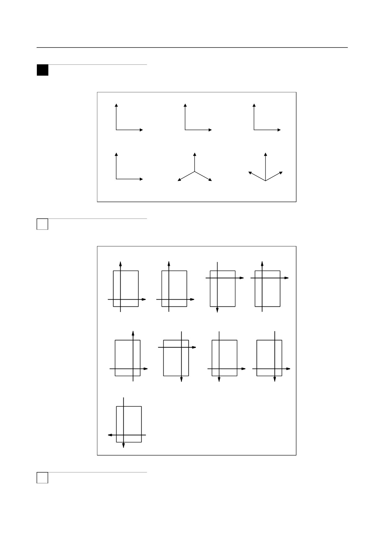
Graphic coordinate system
M
Select a desired graphic coordinate system for tool path drawing then set the corresponding number.
Y
0. XY
Z
1. YZ
Y
2. ZY
X
Y
Z
Z
3. XZ
Z
4. XYZ
Y
5. ZXY
X
Z
X
X
Y
Fig. 13.1.1 (m) Graphic coordinate system
T
Select a desired graphic coordinate system for tool path drawing from the following and set its number in
parameter No. 6510.
Setting
Setting
Setting
Setting
value = 0
value = 1
value = 2
value = 3
Z
X
Z
Z
X
X
Z
X
Setting
Setting
Setting
Setting
value = 4
value = 5
value = 6
value = 7
X
Z
Z
X
Z
X
Z
X
Setting
value = 8
X
Z
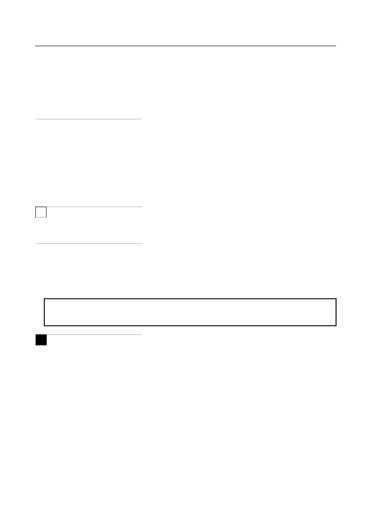
Fig. 13.1.1 (n) Graphic coordinate system
T
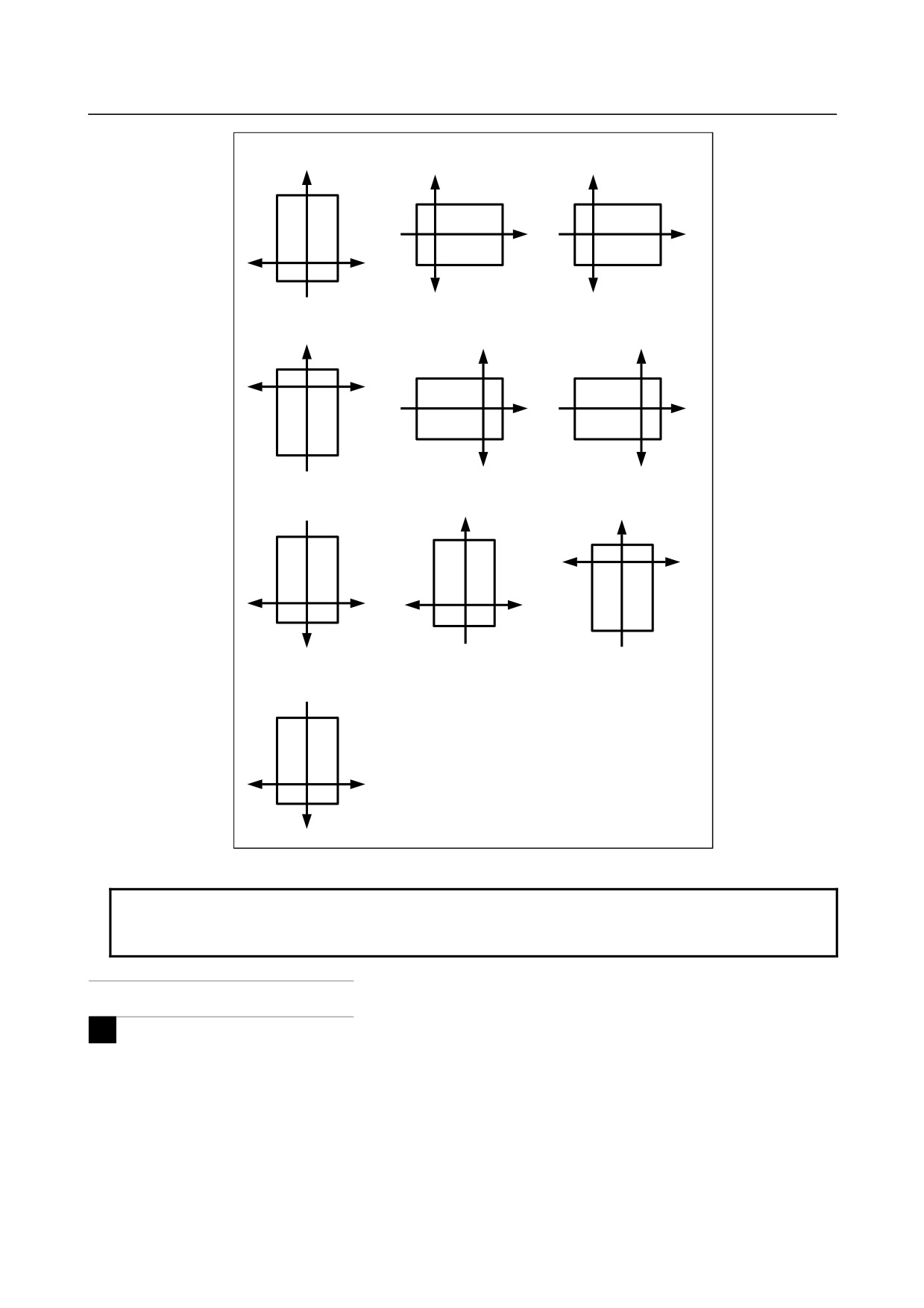
For a two-path lathe system with one spindle and two turrets (bit 1 (SPC) of parameter No. 6500 is 1),
select a desired coordinate system from the following and set its number in parameter No. 6509.
- 696 -
B-64304EN/02
OPERATION
13.GRAPHIC FUNCTION
Setting value = 0 or 10
Setting value = 1 or 11
Setting value = 2 or 12
Z
X1
X2
Z
Z
X2
X1
X2
X1
Setting value = 3 or 13
Setting value = 4 or 14
Setting value = 5 or 15
Z
X1
X2
X2
X1
Z
Z
X2
X1
Setting value = 6 or 16
Setting value = 7 or 17
Setting value = 8 or 18
Z
Z
X1
X2
X2
X1
X1
X2
Z
Setting value = 9 or 19
X1
X2
Z
Fig. 13.1.1 (o) Graphic coordinate system (one spindle and two turrets)
NOTE
The above graphic coordinate system for one spindle and two turrets is enabled
when two paths are displayed at the same time.
M
-
Graphic range setting
For tool path drawing in a drawing area on the PATH GRAPHIC screen, set a graphic range. Two
methods are available:
1. Method by setting the maximum and minimum values of coordinate positions
2. Method by setting the graphic range center and scale factor
Whether method 1 or method 2 is used is determined by which parameters were set most recently. A set
graphic range is preserved even if the power is turned off.
- 697 -

13.GRAPHIC FUNCTION
OPERATION
B-64304EN/02
1.
Method by setting the maximum and minimum values of coordinate
positions
Set the desired graphic range by the maximum and minimum coordinate values in the workpiece
coordinate system.
Drawing is performed so that the entire set range falls within the drawing area.
The graphic range center and scale factor are automatically calculated from the set maximum and
minimum values, and then the settings of the graphic range center and scale factor on the graphic
parameter screen are updated.
Even when the scale factor is automatically determined, the value is clamped to the range of 0.01 to 100.
The maximum value must be larger than the minimum value.
NOTE
When you set the graphic parameters for the maximum and minimum values in
the graphic range, the graphic parameters for the graphic range center and scale
factor are automatically updated. When you change the graphic range center
and scale factor, however, the maximum and minimum values in the graphic
range are not updated.
2. Method by setting the graphic range center and scale factor
Set the central coordinates of the drawing area by coordinate values in the workpiece coordinate system.
Next, set the scale factor to make the graphic range fall within the drawing area.
Set a value of 0.01 to 100 as the scale factor.
With a smaller scale factor, you can perform tool path drawing in a wider range.
With a larger scale factor, you can perform drawing while enlarging the vicinity of the graphic range
center.
T
-
Graphic range setting
For tool path drawing in a drawing area on the PATH GRAPHIC screen, set a graphic range. Two
methods are available:
1. Method by setting the blank length and diameter
2. Method by setting the graphic range center and scale factor
Whether method 1 or method 2 is used is determined by which parameters were set most recently. A set
graphic range is preserved even if the power is turned off.
1. Method by setting the blank length and diameter
Set the length and diameter of a blank in a machining program for drawing.
Drawing is performed so that the entire set range falls within the drawing area.
The graphic range center and scale factor are automatically calculated from the set the length and
diameter of a blank, and then the settings of the graphic range center and scale factor on the graphic
parameter screen are updated.
Even when the scale factor is automatically determined, the value is clamped to the range of 0.01 to 100.
NOTE
When you set the graphic parameters for the blank length and diameter, the
graphic range center and scale factor are automatically updated. When you
change the graphic range center and scale factor, however, the blank length and
diameter are not updated.
- 698 -
B-64304EN/02
OPERATION
13.GRAPHIC FUNCTION
2. Method by setting the graphic range center and scale factor
Set the central coordinates of the drawing area by coordinate values in the workpiece coordinate system.
Next, set the scale factor to make the graphic range fall within the drawing area.
Set a value of 0.01 to 100 as the scale factor.
With a smaller scale factor, you can perform tool path drawing in a wider range.
With a larger scale factor, you can perform drawing while enlarging the vicinity of the graphic range
center.
-
Drawing end block
To perform drawing for a part of a program, set the sequence number of a block at which to end the
drawing. Once the drawing has completed, this value is automatically canceled and change to -1.
-
Automatic erasure
The previous graphic is automatically erased before drawing is started.
1 : The previous graphic is automatically erased immediately before drawing is started.
0 : The previous graphic is not automatically erased.
T
-
Soft limit
When 1 is set, an area of stored stroke limit 1 is drawn with a dashed-two dotted line.
-
Graphic color
Set a graphic color number for a tool path for each of cutting feed and rapid traverse.
1: Red
2: Green
3: Yellow
4: Blue
5: Purple
6: Sky blue
7: White
NOTE
For any value other than the above settings, the graphic color of a tool path is
green.
M
-
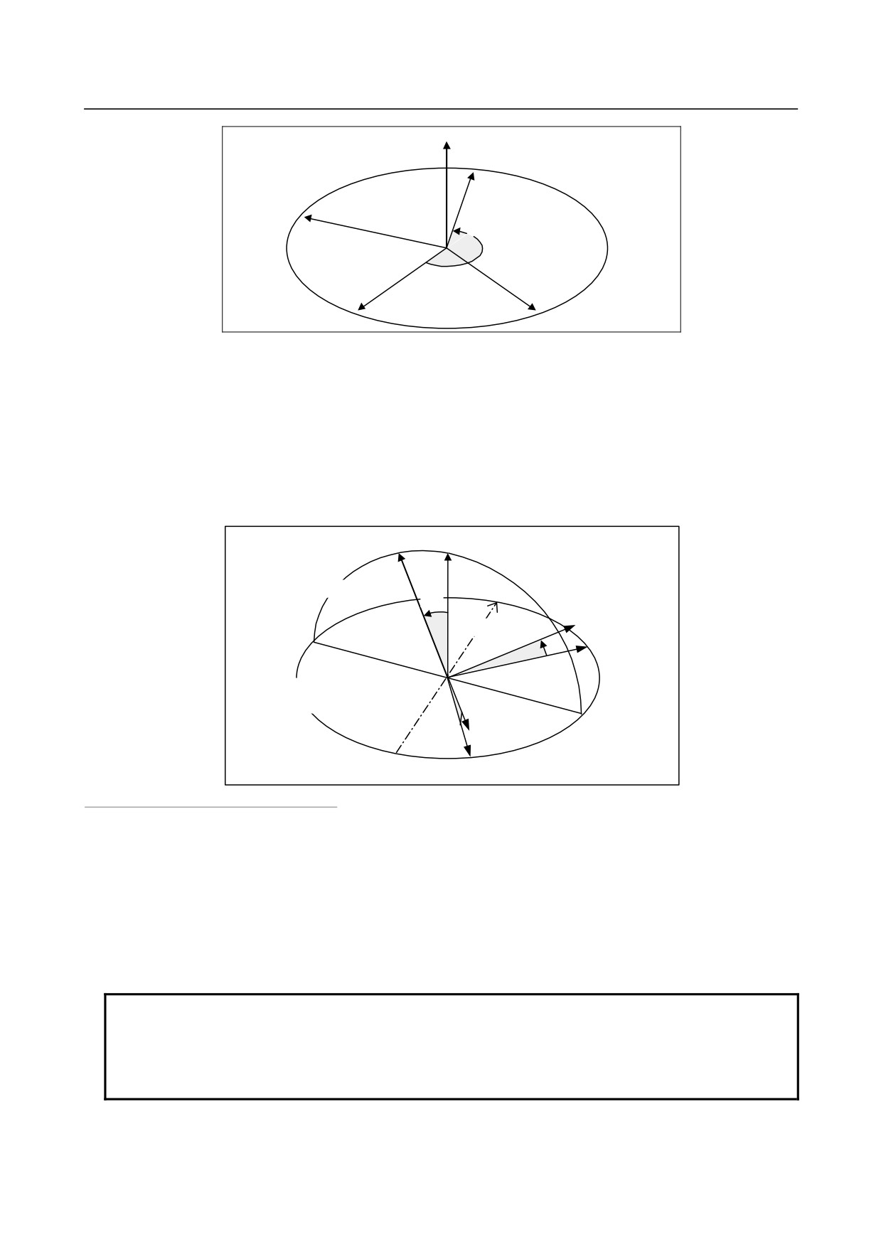
Horizontal rotation angle
When a three-dimensional graphic coordinate system such as 4.XYZ or 5.ZXY is selected, the coordinate
system can be rotated with the horizontal plane used as the rotation plane. Set a rotation angle from
-360° to +360°.
In Fig. 13.1.1 (p) below, the graphic coordinate system XYZ is converted to X”Y”Z” by the following
settings:
Horizontal rotation angle:
210°
- 699 -
13.GRAPHIC FUNCTION
OPERATION
B-64304EN/02
Z
X’
Y’
210°
Horizontal rotation
plane
X
Y
Fig. 13.1.1 (p) Coordinate system rotation in horizontal direction
-
Vertical rotation angle
When a three-dimensional coordinate system such as 4.XYZ or 5.ZXY is selected, the coordinate system
can be rotated with an axis on the horizontal plane specified as a vertical rotation axis. Set a rotation
angle from -360° to +360°.
In Fig. 13.1.1 (q) below, the graphic coordinate system XYZ is converted to X'Y'Z' by the following
settings:
Vertical rotation angle:
20°
Z'
Z
Vertical
rotation plane
20°
Vertical
Y'
rotation axis
Y
Vertical rotation axis
rotation plane
X'
X
Fig. 13.1.1 (q) Coordinate system rotation in vertical direction
-
Graphic axis number
Set which controlled axis to be assigned to which graphic axis.
For each controlled axis, set one of the following graphic axis numbers:
First graphic axis:
1
Second graphic axis:
2
Third graphic axis:
3
Axis not used for drawing:
0
NOTE
1 When 0 is set for all controlled axes, it is assumed that 1, 2, and 3 are set
sequentially for the first to the third controlled axes.
2 With the T series, a tool path is drawn along the first and second graphic axes.
No tool path is drawn along the third graphic axis.
- 700 -
B-64304EN/02
OPERATION
13.GRAPHIC FUNCTION
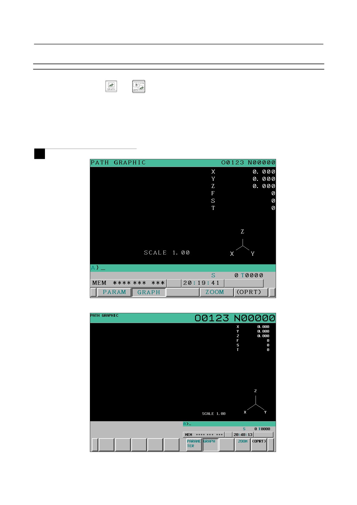
13.1.2 Path Graphic Screen
Explanation
Press the function key
(or
when a small MDI unit is used) and then press the [GRAPH] soft
key to display the PATH GRAPHIC screen.
The PATH GRAPHIC screen mainly consists of three parts.
• Drawing area part for tool path drawing
• Part for display of machining information including a tool position
• Part for display of the graphic coordinate system
M
Fig. 13.1.2 (a) PATH GRAPHIC screen (8.4-inch LCD)
Fig. 13.1.2 (b) PATH GRAPHIC screen (10.4-inch LCD)
- 701 -
13.GRAPHIC FUNCTION
OPERATION
B-64304EN/02
T
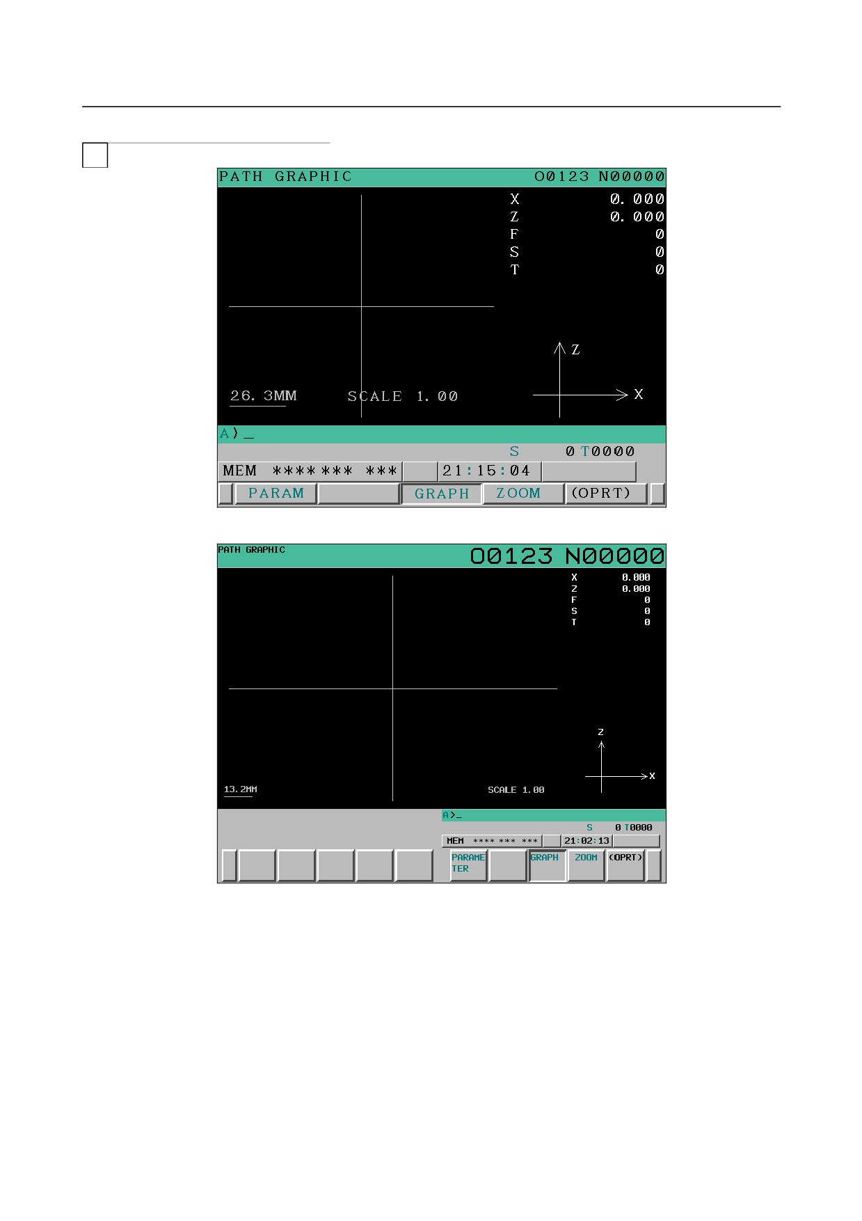
Fig. 13.1.2 (c) PATH GRAPHIC screen (8.4-inch LCD)
Fig. 13.1.2 (d) PATH GRAPHIC screen (10.4-inch LCD)
- 702 -
B-64304EN/02
OPERATION
13.GRAPHIC FUNCTION
T
-
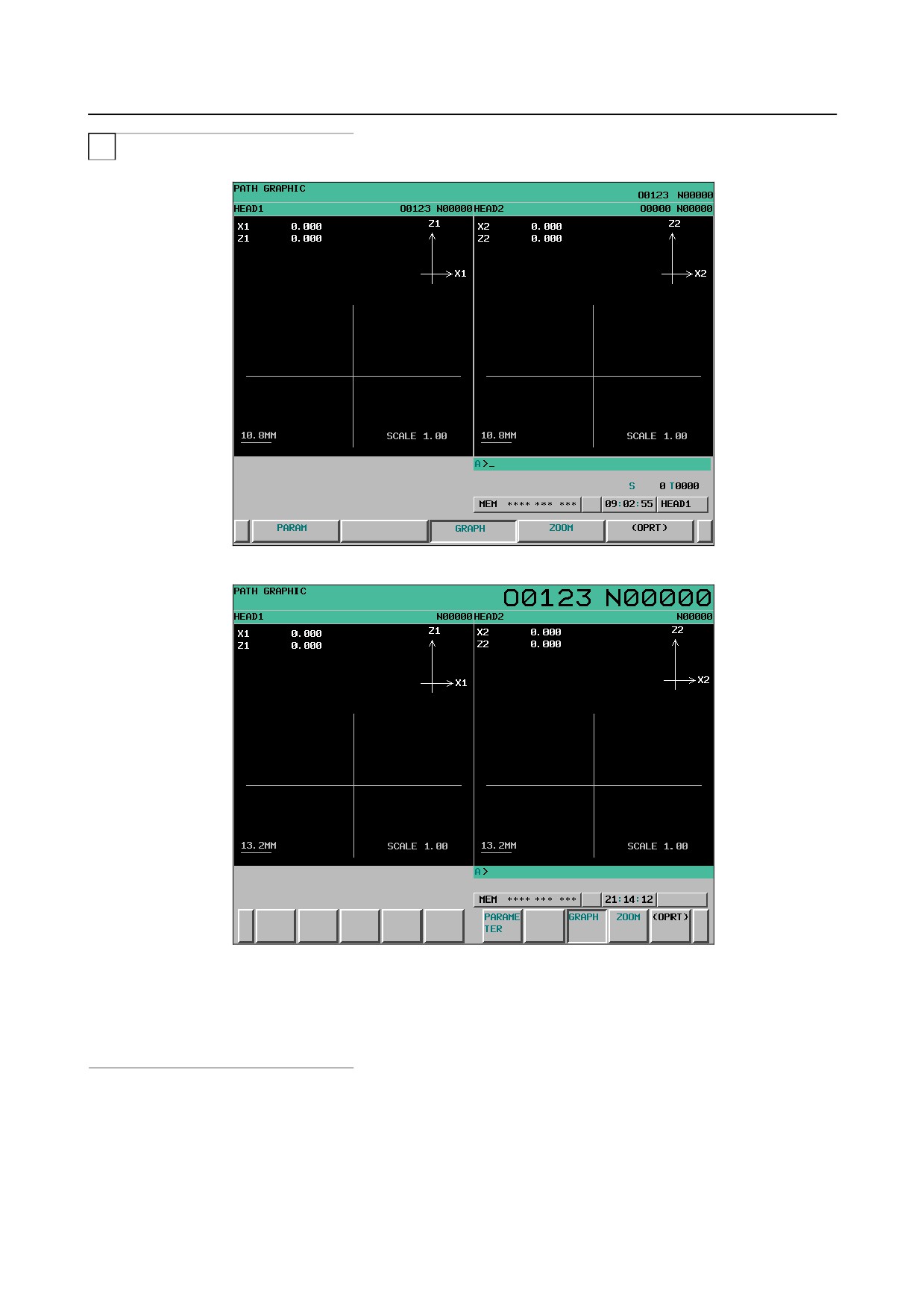
Screen for simultaneously displaying two paths
(Two-path lathe system)
Fig. 13.1.2 (e) PATH GRAPHIC screen (8.4-inch LCD)
Fig. 13.1.2 (f) PATH GRAPHIC screen (10.4-inch LCD)
-
Screen for displaying a single path
When you set bit 2 (DOP) of parameter No. 3193 to disable the simultaneous display of two paths, each
path is displayed in the same way as on the screen for one-path system.
-
Tool path
In the graphic coordinate system set with a graphic parameter, a tool path is drawn in the workpiece
coordinate system. A distinction can be made between travel paths for rapid traverse and cutting feed by
setting graphic colors.
- 703 -
13.GRAPHIC FUNCTION
OPERATION
B-64304EN/02
Even if a tool position changes discontinuously due to origin setting and switching of the workpiece
coordinate system, the tool path is drawn assuming that the tool moves.
Tool path drawing continues even after you switch to another screen.
NOTE
Drawing does not continue and a drawn path is not retained when:
- You switch to the conversational macro screen.
- You switch to a screen displayed by the C language executor.
- You switch to the Manual Guide i screen.
- You start or stop the CNC screen display function.
-
Machining information
On the right side of the screen, you see a position in the workpiece coordinate system as well as the
feedrate (F), spindle speed (S), and tool number (T).
NOTE
Up to three graphic axes are supported for the M series and up to two graphic
axes are supported for the T series.
-
Graphic coordinate system
The coordinate axes and axis names are displayed in the lower right corner of the screen.
- Scale factor and dimensions
When the graphic coordinate system is on a plane, the scale factor for a graphic range and the
dimensional values of measures are displayed.
T
-
Coordinate axes in the workpiece coordinate system
In a drawing area, graphic axes in the workpiece coordinate system are displayed.
Note that you see the position of the workpiece coordinate system set at the time when drawing starts.
During automatic operation, the positions of the coordinate axes are not changed even if the workpiece
coordinate system is changed.
Procedure for drawing a path on the path graphic screen
Procedure
-
Starting drawing
1
Press the function key
(or
when a small MDI unit is used) and set necessary graphic
parameters on the GRAPHIC PARAMETER screen.
2
Press the [GRAPH] soft key to display the PATH GRAPHIC screen.
3
Start automatic or manual operation. Movements of the machine are drawn on the screen.
NOTE
1 Set the machine lock state to perform drawing only without moving the tool.
2 When the feedrate is high, the tool path may not be drawn correctly. In such a
case, decrease the feedrate by performing, for example, a dry run.
- 704 -
B-64304EN/02
OPERATION
13.GRAPHIC FUNCTION
-
Stopping drawing
1
Press the function key
(or
when a small MDI unit is used).
If the PATH GRAPHIC screen does not appear, press the [GRAPH] soft key to display the screen.
2
Tool path drawing stops when automatic operation has completed or is stopped halfway.
-
Erasure of the drawing
Press the [CLEAR] soft key. The tool path drawn so far is erased.
Procedure for enlarging or reducing a drawn path on the path graphic screen
On the tool path graphic screen, you can move the center position of the tool path drawing or enlarge the
tool path drawing while viewing the drawn tool path.
If any of these operations is executed, the tool path already drawn is cleared.
Procedure
1
Press the function key
(or
when a small MDI unit is used).
2
Press the [GRAPH] soft key to display the PATH GRAPHIC screen, and then draw a tool path.
3
Press the [LARGE] soft key
-
Procedure for changing the graphic range by setting a graphic center and
magnification
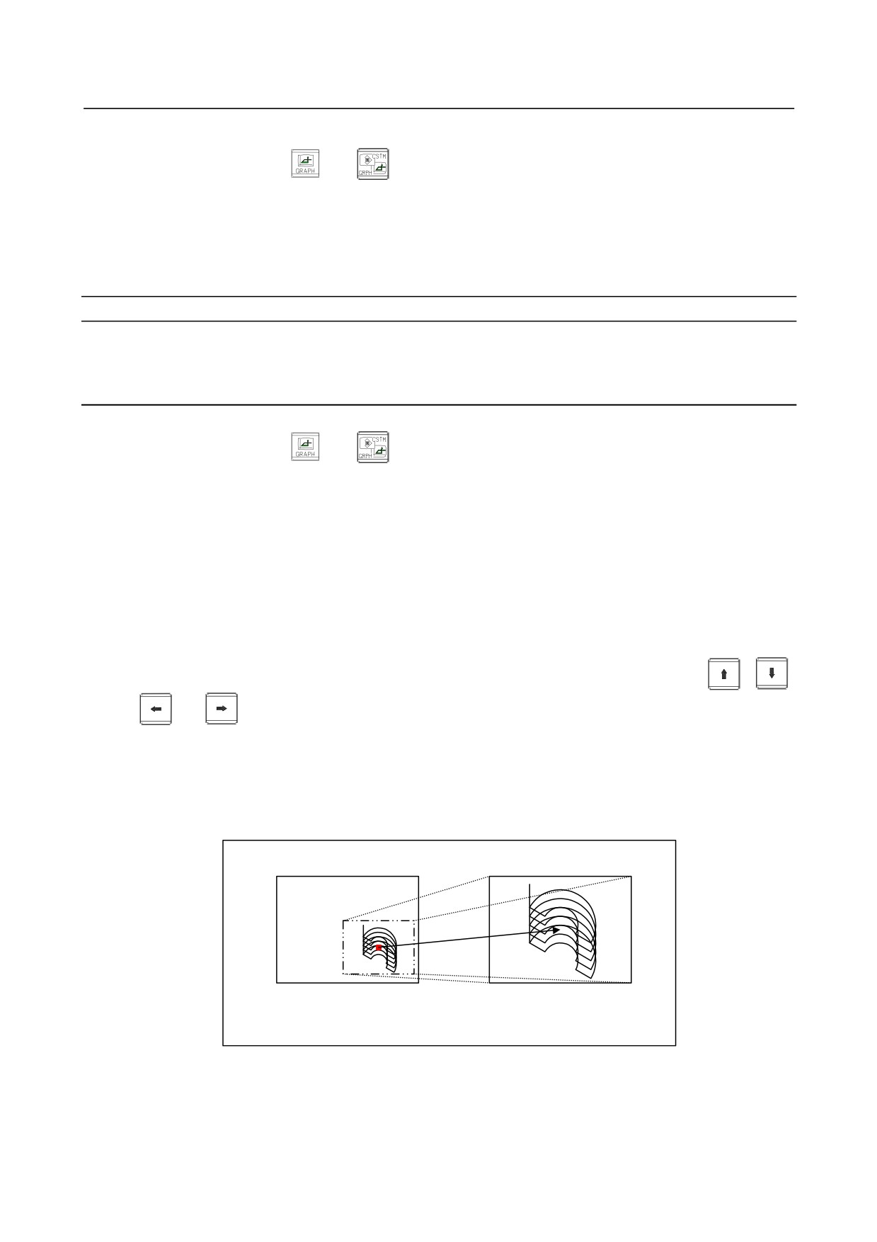
The center position of drawing can be moved. At the same time, the scale can also be changed. So, the
tool path can be enlarged or reduced at a desired new center position.
4
After step 3 described above, press the [CENTER] soft key.
A yellow cursor appears at the center of the screen, and the soft key display is changed.
5
Move the yellow cursor to a new graphic center position by using the cursor key
,
,
, or
6
When changing the scale, key in a value from 0.01 to 100 (magnification) then press the [INPUT]
soft key. An input value is displayed at "SCALE" in the lower-right corner of the screen.
When you press the [+INPUT] soft key, the current magnification is incremented by an input value.
7
Press the [EXEC] soft key to end the operation.
After this step, the setting for graphic movement is effective to enable drawing with the new setting.
Before graphic movement
After graphic movement
Fig. 13.1.2 (g) Graphic movement (magnification = 2.00)
-
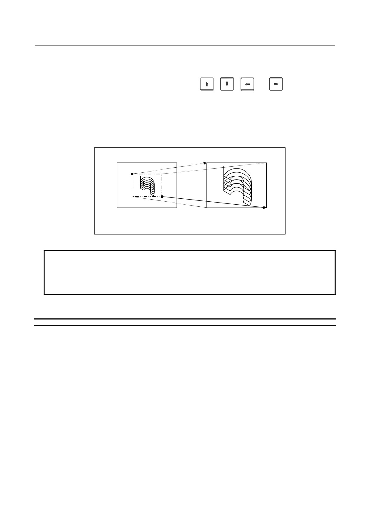
Procedure for changing the graphic range with a rectangle
A tool path can be drawn by enlarging a specified rectangular area.
- 705 -
13.GRAPHIC FUNCTION
OPERATION
B-64304EN/02
4
After step 3 described above, press the [AREA] soft key.
Two cursors, one in red and the other in yellow, appear at the center of the screen, and the soft key
display is changed.
5
Move the yellow cursor by using the cursor key
,
,
, or
. The cursor to be
moved can be switched by pressing the [HI/LO] soft key.
Move the two cursors to the diagonal points of a new rectangular graphic range. A tool path is
drawn next time so that the drawn tool path is contained in this rectangular range.
6
Press the [EXEC] soft key to end the operation.
After this step, the setting made in the above steps is effective to enable drawing in the new graphic
range.
Before graphic enlargement
After graphic enlargement
Fig. 13.1.2 (h) Graphic enlargement
NOTE
1 To stop an enlargement/reduction operation, press the [CANCEL] soft key.
2 Even if you perform an enlargement/reduction operation, the tool path already
drawn on the screen is neither moved nor enlarged. The enlargement/reduction
setting is effective next time drawing is performed.
13.2 DYNAMIC GRAPHIC DISPLAY (M SERIES)
Overview
The dynamic graphic display function has two features:
• Path Drawing
The path of coordinates specified in a program is drawn on the screen.
By displaying a travel path on the screen, the path can be checked easily before performing
machining actually.
• Animation
The figure of a workpiece to be machined by a programmed tool movement is drawn.
By drawing the three-dimensional figure of a workpiece to be machined in an animation-like way,
the intermediate machining process and final figure can be grasped easily.
When machining is performed according to a program, this function can draw a tool path with another
program.
This function performs drawing much faster than the graphic display function based on automatic
operation, so that a program check can be made more swiftly.
This function is distinguished from automatic program operation as indicated by the following
terminology:
- 706 -
B-64304EN/02
OPERATION
13.GRAPHIC FUNCTION
Automatic operation
Operation performed for actual machining
Background operation
Virtual operation performed for drawing
13.2.1 Path Drawing
Overview
The following tool path drawing screens are used to make various settings and execute drawing:
• PATH GRAPHIC (SETTING) screen
This screen is used to set data needed for tool path drawing.
• PATH GRAPHIC (EXECUTION) screen
This screen is used for tool path drawing.
Enlarge or reduce a graphic range, or rotate the graphic coordinate system.
• PATH GRAPHIC (POSITION) screen
This screen is used to indicate the current tool position during automatic operation by showing the
graphic cursor on the path drawn on the PATH GRAPHIC (EXECUTION) screen.
13.2.1.1 PATH GRAPHIC (SETTING) screen
This screen is used to set graphic parameters needed for tool path drawing.
Data set using this screen is made valid by displaying the PATH GRAPHIC (EXECUTION) screen or
executing drawing. If a tool path is already drawn, the path is erased.
Graphic parameter data once set is preserved even if the power is turned off.
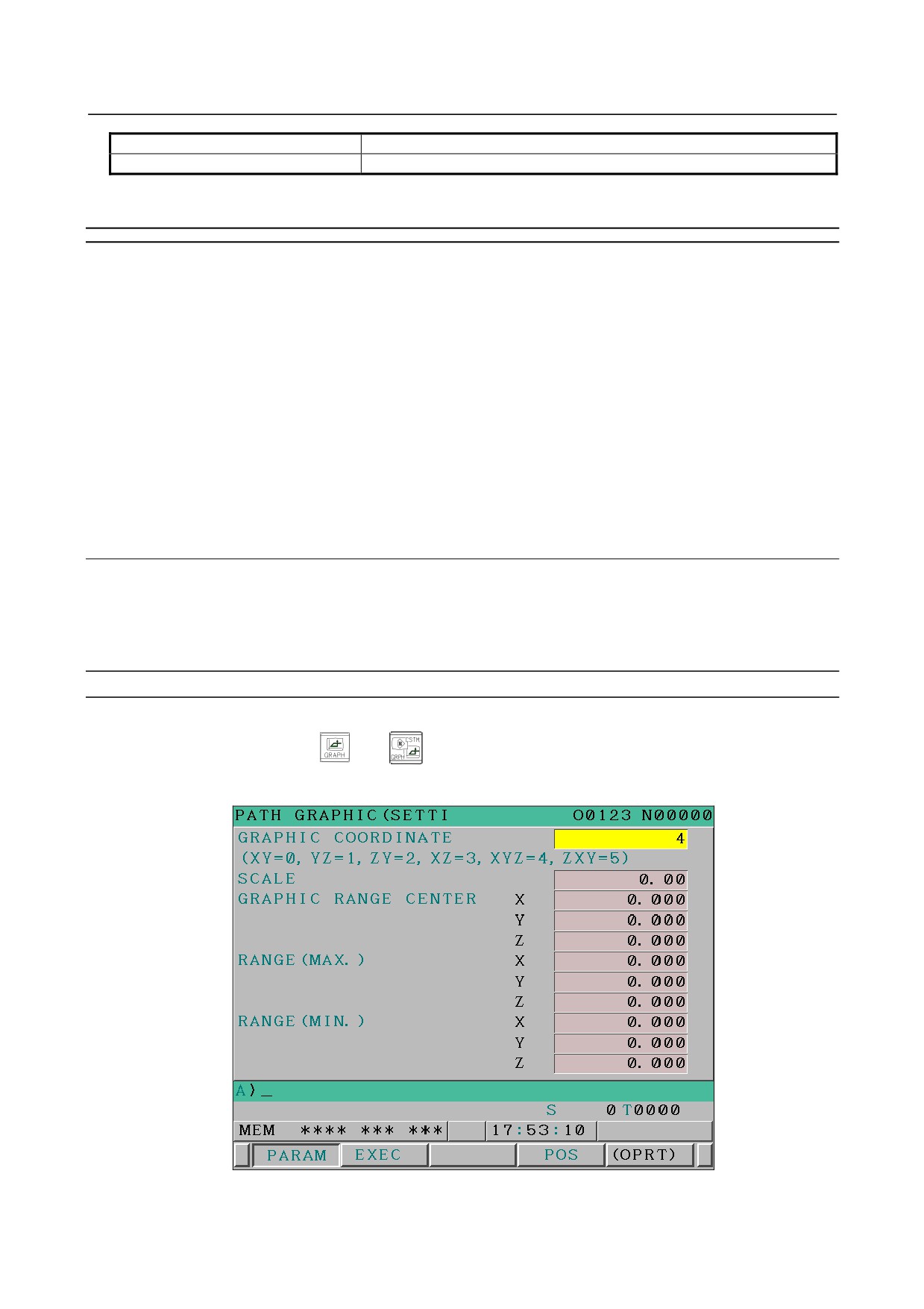
Path Graphic (Setting) screen: Operating procedure
Procedure
1
Press the function key
(or
when a small MDI unit is used) to display the PATH
GRAPHIC (SETTING-1) screen.
Fig. 13.2.1.1 (a) PATH GRAPHIC (SETTING-1) screen (first page) (8.4-inch LCD)
- 707 -
13.GRAPHIC FUNCTION
OPERATION
B-64304EN/02
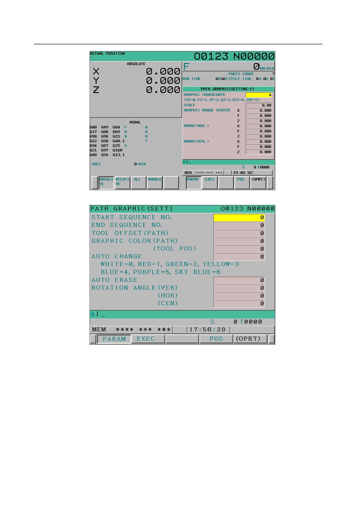
Fig. 13.2.1.1 (b) PATH GRAPHIC (SETTING-1) screen (first page) (10.4-inch LCD)
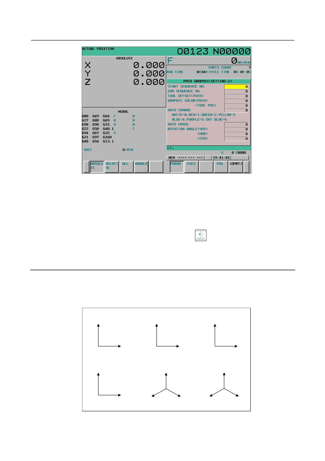
Fig. 13.2.1.1 (c) PATH GRAPHIC (SETTING-2) screen (first page) (8.4-inch LCD)
- 708 -
B-64304EN/02
OPERATION
13.GRAPHIC FUNCTION
Fig. 13.2.1.1 (d) PATH GRAPHIC (SETTING-2) screen (first page) (10.4-inch LCD)
2
Two screens are used for the PATH GRAPHIC (SETTING) screen.
Use the MDI page keys to switch between the screens for display of a desired setting item.
3
Use the MDI cursor keys to place the cursor at the value of the desired item. Use the numeric keys
to type a numeric value to be set.
(The typed numeric value is stored in the key-in buffer.)
4
To directly set the numeric value typed in step 3, press the
key or the [INPUT] soft key.
To increment the current value by the numeric value typed in step 3, press the [+INPUT] soft key.
For each setting item, see the explanation.
Explanation
The setting items on the PATH GRAPHIC (SETTING) screen are described below.
-
Graphic coordinate system (GRAPHIC COORDINATE)
Select a graphic coordinate system for drawing from the following and set its number.
Setting=0 (XY)
Setting=1 (YZ)
Setting=2 (ZY)
Y
Z
Y
X
Y
Z
Setting=3 (XZ)
Setting=5 (XYZ)
Setting=5 (ZXY)
Z
Z
Y
X
X
Y
Z
X
Fig. 13.2.1.1 (e) Graphic coordinate system
- 709 -

13.GRAPHIC FUNCTION
OPERATION
B-64304EN/02
-
Scale (SCALE)
Set the scale factor for drawing in the range of 0.01 to 100.00 (times).
With a small scale factor, it is possible to draw within a wide range.
With a large scale factor, it is possible to draw in the vicinity of the graphic center being enlarged.
NOTE
When 0 is set, the scale factor and central coordinate positions for drawing are
determined according to graphic parameters for the graphic range (maximum
and minimum values).
-
Graphic range center (GRAPHIC RANGE CENTER)
To specify the center coordinates of a graphic range, set a coordinate on each axis in the workpiece
coordinate system of the program executed for drawing.
NOTE
1 Set a coordinate on each axis in the machine coordinate system in case of bit 3
(BGM) of parameter No.11329=1.
2 This setting is effective when a nonzero value is set as the graphic parameter for
the scale factor.
-
Graphic range (maximum value)/(minimum value) (RANGE(MAX.)/(MIN.))
Set the desired graphic range by the maximum and minimum coordinate values in the workpiece
coordinate system.
The scale factor and central coordinate positions for drawing are automatically calculated from the set
maximum and minimum values, and drawing is performed so that the entire set range falls within the
drawing area.
NOTE
1 This setting is effective when 0 is set as the graphic parameter for the scale
factor.
2 The scale factor for drawing is clamped to the range of 0.01 to 100.00.
3 Set the position of the maximum value larger than the minimum value.
4 When bit 3 (BGM) of parameter No. 11329 is 1, set a coordinate value on each
axis in the machine coordinate system.
-
Start/end sequence numbers (START/END SEQUENCE NO.)
Set start and end sequence numbers for drawing. A drawing target program is executed from the
beginning, but drawing is performed only for the portion between the start and end sequence numbers.
When 0 is specified as the start sequence number, drawing is performed from the beginning of the
program.
When 0 is specified as the end sequence number, drawing is performed until the end of the program is
reached. The sequence numbers are checked with no distinction between the main program and
subprogram.
-
Tool offset (Path) (TOOL OFFSET(PATH))
For tool path drawing, whether to enable or disable the tool offset function (tool length compensation,
cutter compensation) can be selected.
Setting
0: The tool offset function is enabled for drawing.
1: The tool offset function is disabled for drawing.
- 710 -
B-64304EN/02
OPERATION
13.GRAPHIC FUNCTION
-
Graphic color (GRAPHIC COLOR)
Set colors to be used for tool path drawing.
The colors that can be set are indicated below together with their setting values:
Graphic color
White
Red
Green
Yellow
Blue
Purple
Light blue
Setting value
0
1
2
3
4
5
6
Path (PATH)
Set colors to be used for a drawn tool path.
Tool position (TOOL POS)
Set a graphic cursor color to be used for PATH GRAPHIC (POSITION) screen.
-
Automatic change (AUTO CHANGE)
T codes specified in a drawing target program can be used to automatically change the color of a tool path
during drawing.
Setting
0: The automatic change is not performed.
1: The automatic change is performed.
When 1 is set, the setting for the tool path color is incremented by 1 each time a T code is executed; the
tool path color changes accordingly. When the setting reaches 6, it is reset to 0.
-
Auto erase (AUTO ERASE)
When drawing is started with the [AUTO] or [START] soft key from a state where drawing is not being
executed or is not stopped temporarily, the previously drawn path can be erased.
Setting
0: The previously drawn path is not erased.
1: The previously drawn path is erased.
-
Rotation angle
Set a rotating angle of the graphic coordinate system that centers on the graphic range center. The rotating
angle is a range of -360°-+360°.
Set a rotating angle as a reference position (position of the rotating angle 0°) on the indicated direction of
each graphic coordinate system.
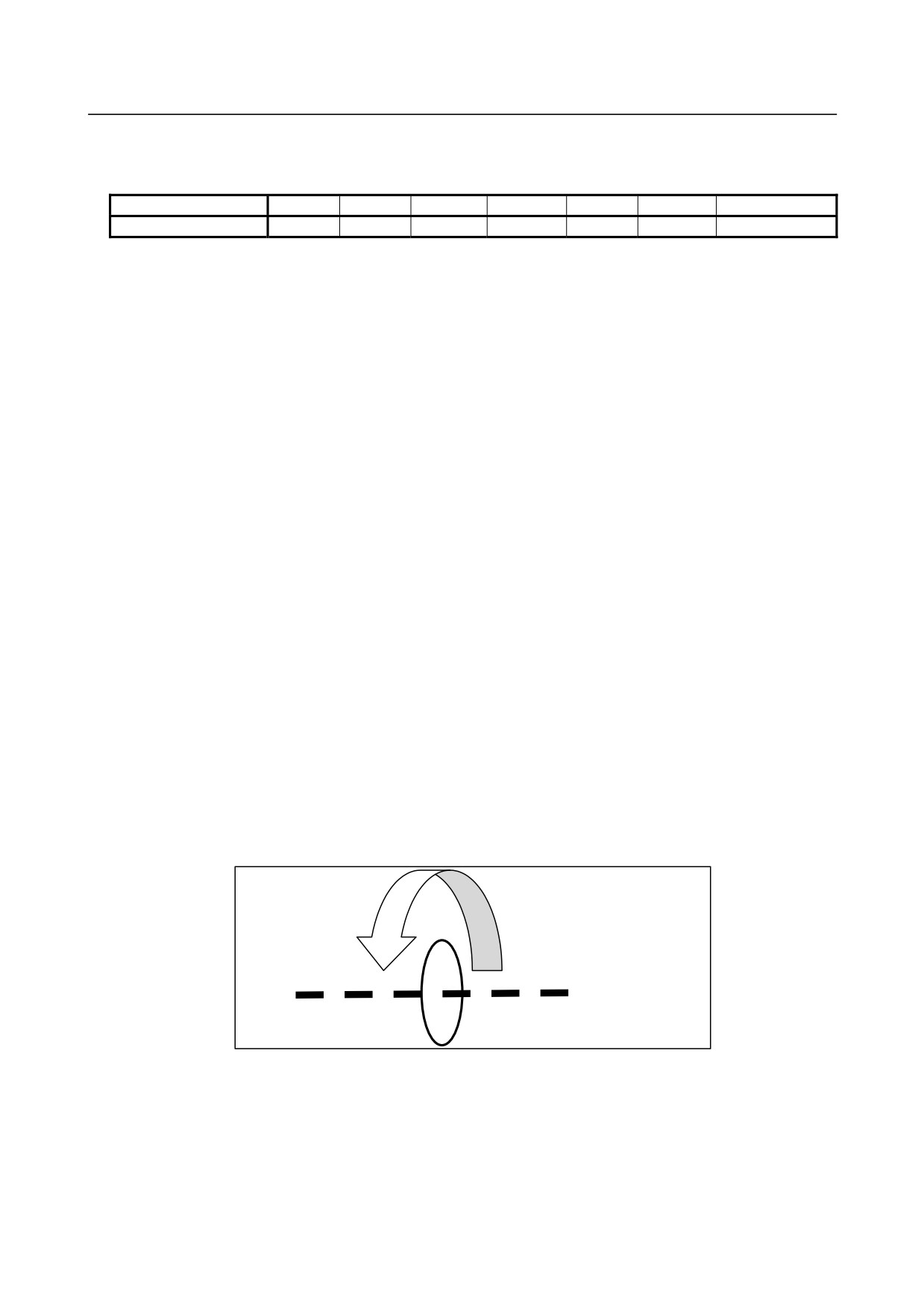
Vertical plane rotation angle
Set a rotating angle at the horizontal direction center in front of the screen.
The rotation direction is as follows.
-
+
Rotation center
- 711 -
13.GRAPHIC FUNCTION
OPERATION
B-64304EN/02
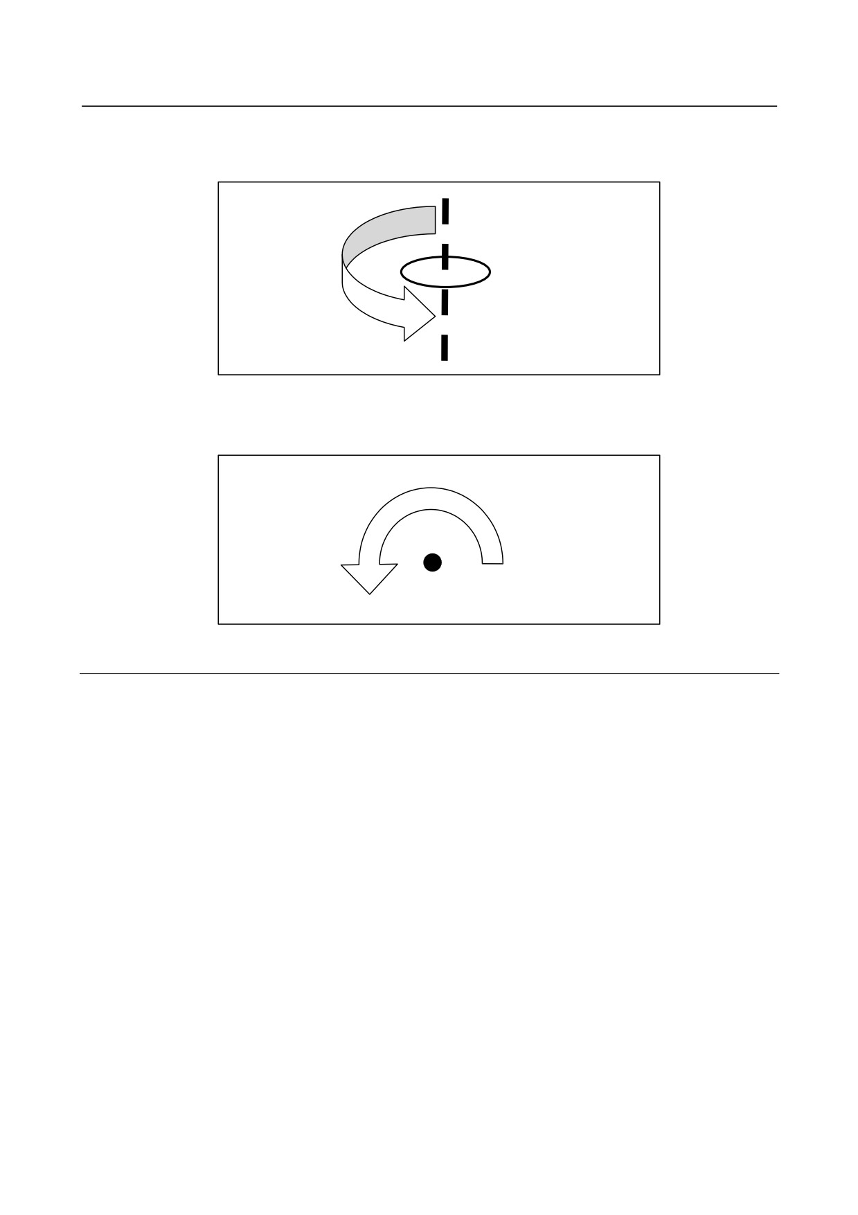
Horizontal plane rotation angle
Set a rotating angle at the vertical direction center in front of the screen.
The rotation direction is as follows.
-
Rotation center
+
Screen center rotation angle
Set a rotating angle at the vertical direction center of the screen plane.
The rotation direction is as follows.
-
+
Rotation center
13.2.1.2 PATH GRAPHIC (EXECUTION) screen
The PATH GRAPHIC screen is used to draw a tool path. The following operations can be performed:
• Starting/ending tool path drawing
• Rewind of a drawing target program
• Erasing a drawn tool path
• Enlarging/reducing/moving the graphic range
• Changing/rotating the graphic coordinate system
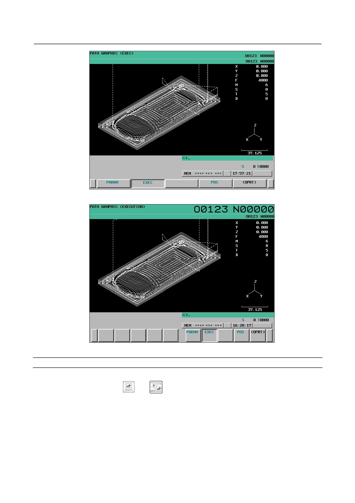
The screen is composed of the following items:
(1) Drawing area
(2) Status display of Background operation
(3) Program number and sequence number for drawing execution
(4) Current coordinates
(5) Feedrate and M/S/T/D code instruction information
(6) Graphic coordinate system
(7) Actual dimension line
- 712 -
B-64304EN/02
OPERATION
13.GRAPHIC FUNCTION
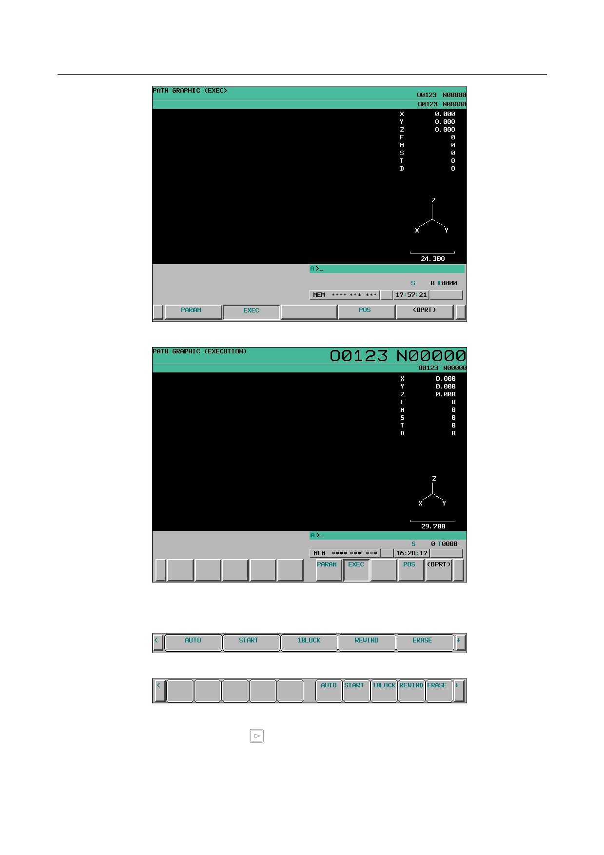
Fig. 13.2.1.2 (a) PATH GRAPHIC (EXECUTION) screen (8.4-inch LCD)
Fig. 13.2.1.2 (b) PATH GRAPHIC (EXECUTION) screen (10.4-inch LCD)
PATH GRAPHIC (EXECUTION) screen: Procedure
Procedure
1
Press the function key
(or
when a small MDI unit is used) to display the PATH
GRAPHIC (SETTING-1) screen.
2
Press the [EXEC] soft key. The PATH GRAPHIC screen is displayed.
- 713 -
13.GRAPHIC FUNCTION
OPERATION
B-64304EN/02
Fig. 13.2.1.2 (c) PATH GRAPHIC (EXECUTION) screen (8.4-inch LCD)
Fig. 13.2.1.2 (d) PATH GRAPHIC (EXECUTION) screen (10.4-inch LCD)
3
Press the [(OPRT)] soft key. The soft keys for tool path drawing are displayed.
Fig. 13.2.1.2 (e) PATH GRAPHIC (EXECUTION) screen (operation) (8.4-inch LCD)
Fig. 13.2.1.2 (f) PATH GRAPHIC (EXECUTION) screen (operation) (10.4-inch LCD)
4
Press the continuous menu key
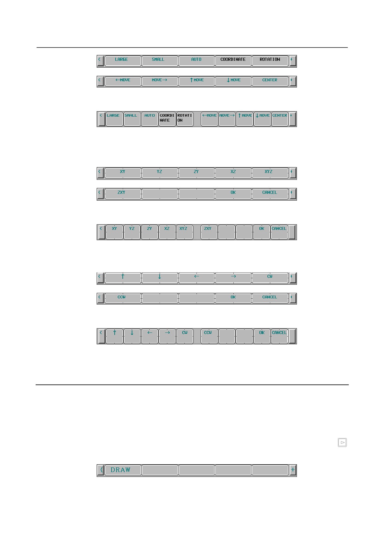
to display the soft keys for enlarging/reducing/moving the
graphic range.
- 714 -
B-64304EN/02
OPERATION
13.GRAPHIC FUNCTION
Fig. 13.2.1.2 (g) PATH GRAPHIC (EXECUTION) screen
(enlarging/reducing/moving the graphic range) (8.4-inch LCD)
Fig. 13.2.1.2 (h) PATH GRAPHIC (EXECUTION) screen
(enlarging/reducing/moving the graphic range) (10.4-inch LCD)
5
Press the [COORDINATE] soft key to display the soft keys for changing the graphic coordinate
system.
Fig. 13.2.1.2 (i) PATH GRAPHIC (EXECUTION) screen
(changing the graphic coordinate system) (8.4-inch LCD)
Fig. 13.2.1.2 (j) PATH GRAPHIC (EXECUTION) screen
(changing the graphic coordinate system) (10.4-inch LCD)
6
Press the [ROTATION] soft key to display the soft keys for rotating the graphic coordinate system.
Fig. 13.2.1.2 (k) PATH GRAPHIC (EXECUTION) screen
(rotating the graphic coordinate system) (8.4-inch LCD)
Fig. 13.2.1.2 (l) PATH GRAPHIC (EXECUTION) screen
(rotating the graphic coordinate system) (10.4-inch LCD)
For the operation of each soft key, see the explanation.
Explanation
- Graphic program selection
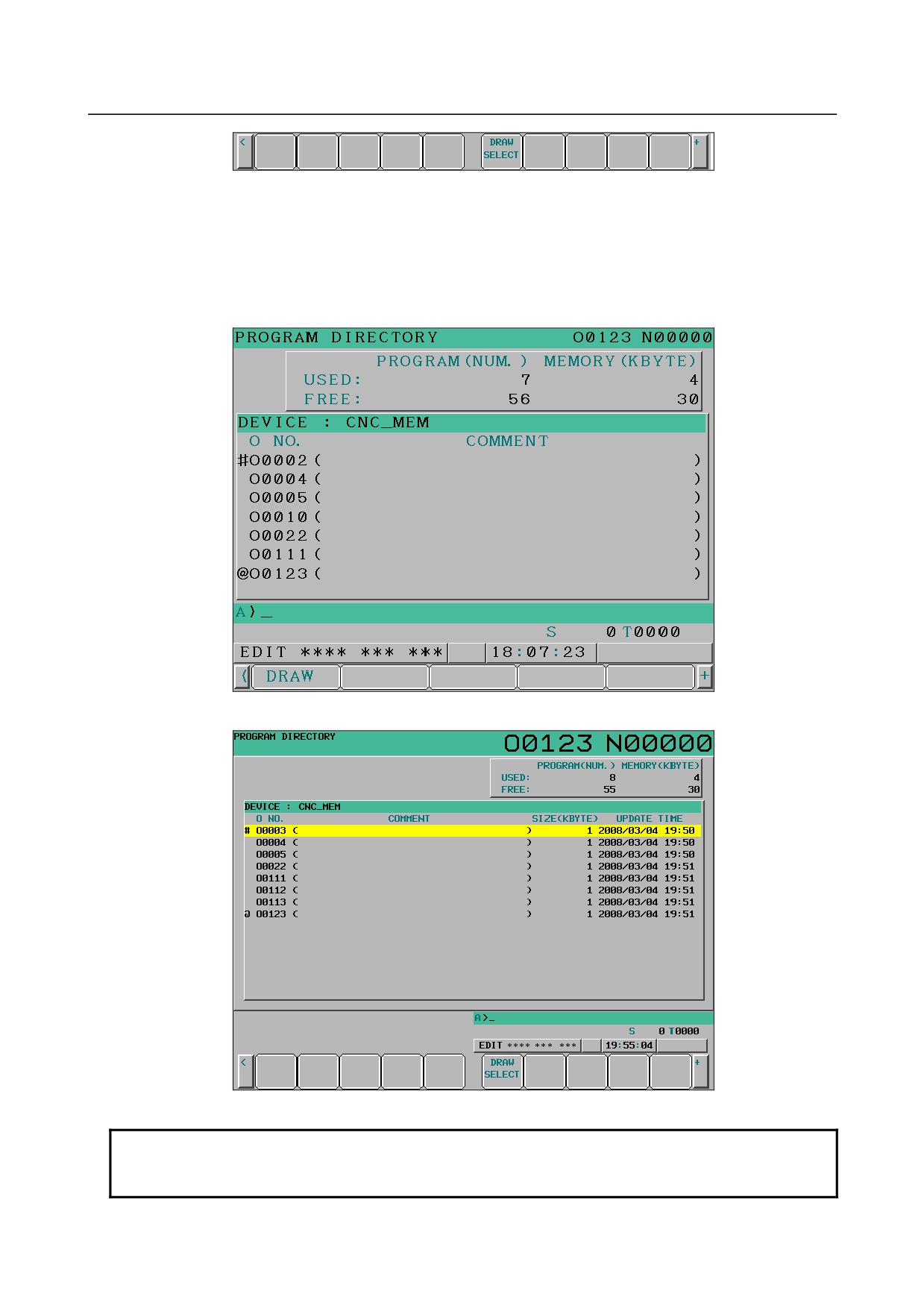
Drawing is performed for the program selected as the main program. On the program list screen,
however, you can select another program only for drawing.
The procedure is as follows.
1
Press the [(OPRT)] soft key on the program list screen, and then press the continuous menu key
several times to display the [DRAW SELECT] soft key.
Fig. 13.2.1.2 (m) Program list screen ([DRAW SELECT] soft key) (8.4-inch LCD)
- 715 -
13.GRAPHIC FUNCTION
OPERATION
B-64304EN/02
Fig. 13.2.1.2 (n) Program list screen ([DRAW SELECT] soft key) (10.4-inch LCD)
2
Use the MDI keys to type the number of a program for drawing.
3
Press the [DRAW SELECT] soft key.
The number of the program selected in the above steps is prefixed with "#" indicating that the program is
selected for drawing.
Fig. 13.2.1.2 (o) Program list screen (drawing target program selection state) (8.4-inch LCD)
Fig. 13.2.1.2 (p) Program list screen (drawing target program selection state) (10.4-inch LCD)
NOTE
The file that can be selected as the drawing target program is only a file that can
be selected as the main program.
- 716 -
B-64304EN/02
OPERATION
13.GRAPHIC FUNCTION
-
Starting / Stopping drawing
To draw the tool path of a program selected for drawing, press one of the following soft keys displayed
by step 3 mentioned above:
•
[AUTO] soft key
This soft key performs automatic scaling. Before drawing is started, the maximum and minimum
coordinate values for the drawing target program are determined and set as the graphic parameters
for the maximum and minimum values in the graphic range, and 0 is set for the scale factor and
graphic range center. Drawing is then started. The tool path is drawn properly on the screen.
•
[START] soft key
This soft key starts drawing from the head of the program.
•
[1BLOCK] soft key
This soft key executes the program for drawing and stops temporarily on a block-by-block basis as
with ordinary single block stop operation.
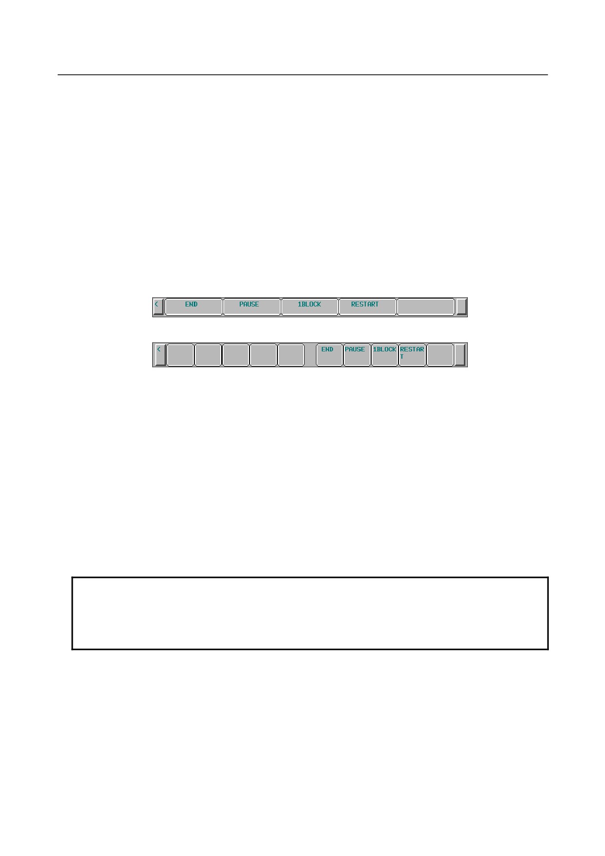
If a program is executed with a soft key above, the soft key display is changed to the following:
Fig. 13.2.1.2 (q) Soft keys displayed during drawing execution (8.4-inch LCD)
Fig. 13.2.1.2 (r) Soft keys displayed during drawing execution (10.4-inch LCD)
The operations of these soft keys are as follows:
•
[END] soft key
This soft key terminates the execution of the drawing target program to stop drawing.
•
[PAUSE] soft key
This soft key temporarily stops the execution of the drawing target program to stop drawing
temporarily.
•
[1BLOCK] soft key
This soft key executes the program for drawing and stops drawing temporarily on a block-by-block
basis as with ordinary single block stop operation.
•
[RESTART] soft key
If the
[RESTART] soft key is pressed in the stop state set by the [PAUSE] soft key or the
[1BLOCK] soft key, the execution of drawing can be restarted from the block where drawing is
stopped.
NOTE
When the new path was drawn by the operation of starting drawing without
erasing of the old path before the operation, it is impossible to redraw the old
path by each operation of enlarging/reducing/moving the graphic range and
changing/rotating the graphic coordinate system.
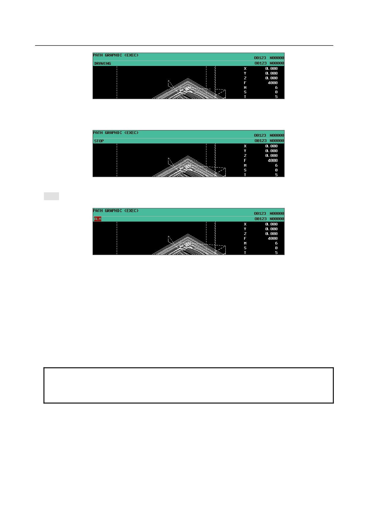
The state of drawing is indicated as follows:
DRAWING: Indicates that drawing is being executed.
- 717 -
13.GRAPHIC FUNCTION
OPERATION
B-64304EN/02
Fig. 13.2.1.2 (s) State indication during drawing
STOP: Indicates that drawing is temporarily stopped.
Fig. 13.2.1.2 (t) State indication during temporary stop
ALM: Indicates that occurring of alarm in the Background operation.
Fig. 13.2.1.2 (u) State indication during occurring of alarm
-
End of drawing
When M02 or M30 is executed, the program executed for drawing terminates drawing.
Upon program termination, the soft key display returns to the soft keys (Fig. 13.2.1.2 (e)/(f)) displayed
before drawing is started.
-
Rewind of a drawing target program
If the execution of drawing of a selected program has ended or is stopped halfway, press the [REWIND]
soft key to restart drawing from the beginning of the program.
-
Erasing a drawn tool path
Press the [ERASE] soft key to erase a drawn tool path.
NOTE
1 If the screen display is switched during tool path drawing, the background
operation is stopped to end drawing.
2 A tool path once drawn is erased when the screen display is switched.
-
Enlarging/reducing the graphic range
The following soft keys displayed by step 4 are used:
•
[LARGE] soft key
This soft key increases the scale to enlarge the graphic range.
•
[SMALL] soft key
This soft key decreases the scale to reduce the graphic range.
•
[AUTO] soft key
When the graphic parameters for the graphic range (maximum and minimum values) are set, this soft
- 718 -

B-64304EN/02
OPERATION
13.GRAPHIC FUNCTION
key automatically scales the set graphic range so that the range falls within the drawing area. When
the graphic range (maximum and minimum values) is not set (0 is set), this operation is disabled.
NOTE
1 Set the unit of scale for one enlargement/reduction operation in parameter No.
14713.
2 An enlargement/reduction scale used here is set in the graphic parameter for
scale.
-
Moving the graphic range
The following soft keys displayed by step 4 are used:
•
[←MOVE] soft key
This soft key moves the graphic range to left.
•
[MOVE→] soft key
This soft key moves the graphic range to right.
•
[↑MOVE] soft key
This soft key moves the graphic range upward.
•
[↓MOVE] soft key
This soft key moves the graphic range downward.
•
[CENTER] soft key
This soft key returns the graphic range to the original position.
NOTE
1 Set the travel increment made by one horizontal move operation in parameter
No. 14714.
2 Set the travel increment made by one vertical move operation in parameter No.
14715.
3 The graphic range modified here is not set in the graphic parameter for graphic
range center.
-
Changing the graphic coordinate system
The following soft keys displayed by step 5 are used.
A graphic coordinate system selected here is the same one as set in the graphic parameter for the graphic
coordinate system.
•
[XY] soft key
This soft key selects the graphic coordinate system of XY (with a setting of 0).
•
[YZ] soft key
This soft key selects the graphic coordinate system of YZ (with a setting of 1).
•
[ZY] soft key
This soft key selects the graphic coordinate system of ZY (with a setting of 2).
•
[XZ] soft key
This soft key selects the graphic coordinate system of XZ (with a setting of 3).
•
[XYZ] soft key
This soft key selects the graphic coordinate system of XYZ (with a setting of 4).
•
[ZXY] soft key
This soft key selects the graphic coordinate system of ZXY (with a setting of 5).
•
[OK] soft key
This soft key changes the current graphic coordinate system to the graphic coordinate system
selected by one of the soft keys above.
•
[CANCEL] soft key
This soft key cancels the graphic coordinate system selected by one of the soft keys above to return
to the original graphic coordinate system.
- 719 -

13.GRAPHIC FUNCTION
OPERATION
B-64304EN/02
NOTE
The graphic coordinate system selected here is set in the graphic parameter for
the graphic coordinate system.
-
Rotating the graphic coordinate system
The following soft keys displayed by step 6 are used.
•
[↑] soft key
This soft key rotates the graphic coordinate system upward.
•
[↓] soft key
This soft key rotates the graphic coordinate system downward.
•
[←] soft key
This soft key rotates the graphic coordinate system to left.
•
[→] soft key
This soft key rotates the graphic coordinate system to right.
•
[CW] soft key
This soft key rotates the graphic coordinate system clockwise.
•
[CCW] soft key
This soft key rotates the graphic coordinate system counterclockwise.
•
[OK] soft key
This soft key changes the rotation angle of the current graphic coordinate system to the one set by
one of the soft keys above.
•
[CANCEL] soft key
This soft key cancels the rotation of the graphic coordinate system performed by one of the soft keys
above to return to the original graphic coordinate system.
NOTE
1 Set the travel increment made by one rotation operation in parameter No. 14716.
2 The rotation angle of the graphic coordinate system set here is not set in the
graphic parameter for rotation angle.
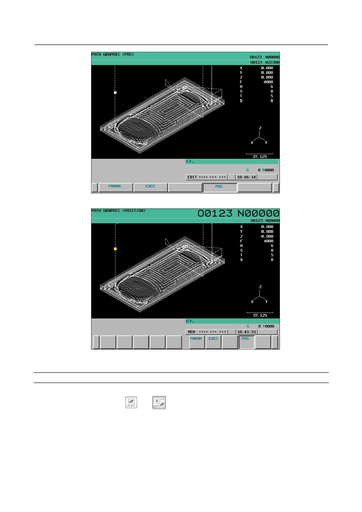
13.2.1.3 PATH GRAPHIC (POSITION) screen
The PATH GRAPHIC (POSITION) screen indicates the current position during operation by the cursor
on a tool path drawn on the PATH GRAPHIC (EXECUTION) screen; you can check a programmed tool
movement during automatic operation.
The screen is composed of the following items:
(1) Drawing area
(2) Current coordinates
(3) Feedrate and M/S/T/D code instruction information
(4) Graphic coordinate system
(5) Actual dimension line
(6) Cursor to show current position
- 720 -
B-64304EN/02
OPERATION
13.GRAPHIC FUNCTION
Fig. 13.2.1.3 (a) PATH GRAPHIC (POSITION) screen (8.4-inch LCD)
Fig. 13.2.1.3 (b) PATH GRAPHIC (POSITION) screen (10.4-inch LCD)
PATH GRAPHIC (POSITION) screen: Procedure
Procedure
1
Press the function key
(or
when a small MDI unit is used) to display the PATH
GRAPHIC (SETTING-1) screen.
2
Press the [POS] soft key.
The screen display changes to the PATH GRAPHIC (POSITION) screen and the cursor indicating
the tool position is displayed.
- 721 -
13.GRAPHIC FUNCTION
OPERATION
B-64304EN/02
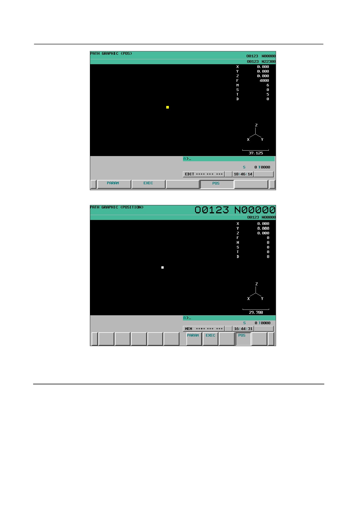
Fig. 13.2.1.3 (c) PATH GRAPHIC (POSITION) screen (8.4-inch LCD)
Fig. 13.2.1.3 (d) PATH GRAPHIC (POSITION) screen (10.4-inch LCD)
For the method of checking the current tool position, see the explanation.
Pressing a soft key other than the [POS] soft key displays the corresponding screen.
Explanation
Use the following procedure to check the tool position during operation on the PATH GRAPHIC
(POSITION) screen:
(1) Draw the tool path of the selected program on the PATH GRAPHIC (EXECUTION) screen.
(2) After the end of drawing, switch the screen display to the PATH GRAPHIC (POSITION) screen.
(3) Start automatic operation with the program executed for tool path drawing.
After automatic operation is started, the blinking cursor moves along the drawn tool path as the tool
moves. The cursor blinking rate is fast when the tool is moving, and the cursor blinking rate is slow
when the tool is stopped.
- 722 -

B-64304EN/02
OPERATION
13.GRAPHIC FUNCTION
The following items displayed on the screen are provided for the program under automatic operation:
• Current coordinates
• Feedrate and M/S/T/D code specification information
NOTE
1 A tool path drawn by setting the tool offset parameter to 1 (to disable the tool
offset function) is different from the actual tool path. In this case, the cursor
indicating the tool position may not move along the drawn tool path.
2 The tool path cannot be drawn correctly if a command not supporting drawing or
a command that specifies operation different from operation performed during
drawing is specified or if an operation dependent on the operation state or
setting on the machine side is performed. So, the tool path in actual operation
may differ from a drawn tool path. In this case, the cursor indicating the tool
position does not move along the drawn tool path.
3 When the graphic parameter of the graphic coordinate system, graphic range
(maximum and minimum values), scale, graphic range center, and rotation angle
is changed, the drawn tool path drawn is erased.
Therefore, please draw the tool path again on the PATH GRAPHIC
(EXECUTION) screen to display the tool position by setting the changed graphic
parameter.
13.2.2 Animation
Overview
For animation drawing, make necessary settings and perform operations for drawing execution on the
following screens:
• ANIME GRAPHIC (SETTING) screen
On this screen, data required to execute animation drawing can be set.
• ANIMATION GRAPHIC (EXECUTION) screen
This screen is used for animation drawing.
On this screen, the graphic range can be reduced/enlarged, and the graphic coordinate system can be
rotated.
• ANIMATION GRAPHIC (3-PLANE) screen
On this screen, a three-plane diagram can be drawn for a machining profile that has been drawn.
In addition, the positions of side views and cross sections can be changed.
13.2.2.1 ANIME GRAPHIC (SETTING) screen
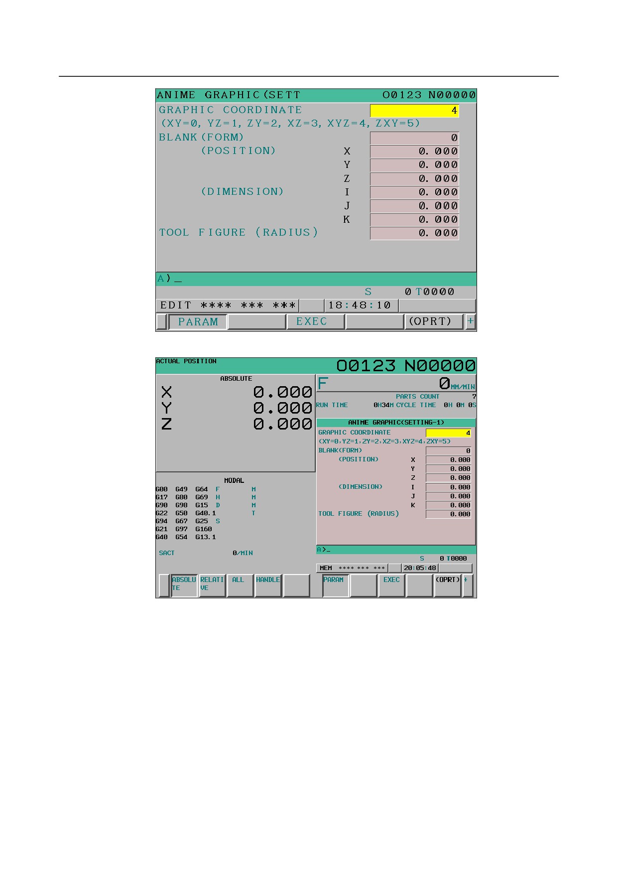
This screen is used to set graphic parameters needed for animation drawing.
Data set using this screen is made valid by displaying the ANIMATION GRAPHIC (EXECUTION)
screen or executing drawing.
Graphic parameter data once set is preserved even if the power is turned off.
ANIME GRAPHIC (SETTING) screen: Procedure
Procedure
1
Press the function key
(or
when a small MDI unit is used) to display the ANIME
GRAPHIC (SETTING-1) screen.
- 723 -
13.GRAPHIC FUNCTION
OPERATION
B-64304EN/02
Fig. 13.2.2.1 (a) ANIME GRAPHIC (SETTING-1) screen (8.4-inch LCD)
Fig. 13.2.2.1 (b) ANIME GRAPHIC (SETTING-1) screen (10.4-inch LCD)
- 724 -
B-64304EN/02
OPERATION
13.GRAPHIC FUNCTION
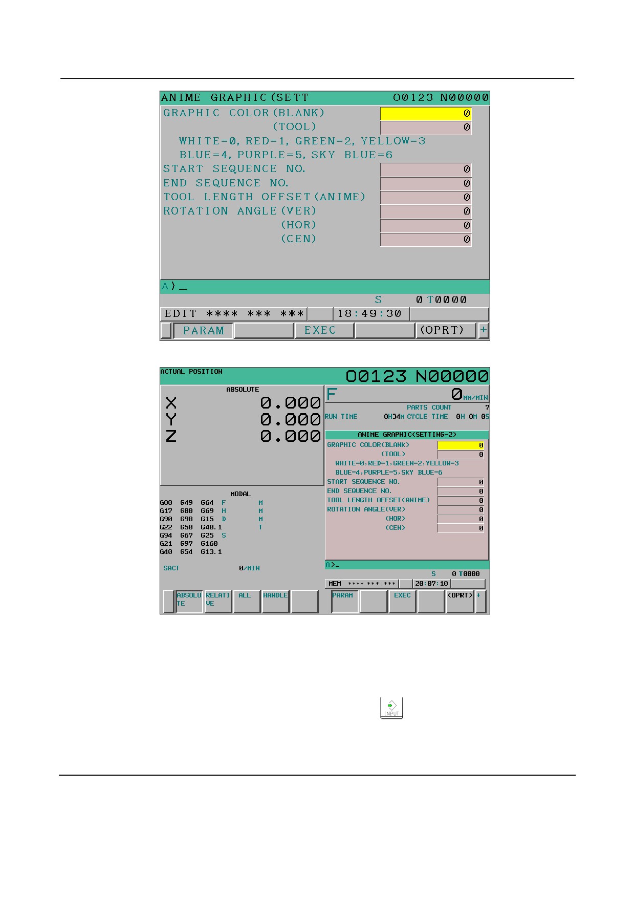
Fig. 13.2.2.1 (c) ANIME GRAPHIC (SETTING-2) screen (8.4-inch LCD)
Fig. 13.2.2.1 (d) ANIME GRAPHIC (SETTING-2) screen (10.4-inch LCD)
2
Two screens are used for the ANIME GRAPHIC (SETTING) screen.
Use the MDI page keys to switch between the screens for display of a desired setting item.
3
Use the MDI cursor keys to place the cursor at the value of the desired item. Use the numeric keys
to type a numeric value to be set.
(The typed numeric value is stored in the key-in buffer.)
4
To directly set the numeric value typed in step 3, press the
key or the [INPUT] soft key.
To increment the current value by the numeric value typed in step 3, press the [+INPUT] soft key.
For each setting item, see the explanation.
Explanation
The setting items on the ANIME GRAPHIC (SETTING) screen are described below.
However, the graphic parameters listed below are shared for tool path drawing. So, refer to the
explanation of the PATH GRAPHIC (SETTING) screen for tool path drawing.
- 725 -