FANUC Series 0i-MODEL D, Series 0i Mate-MODEL D. OPERATOR'S MANUAL - page 26
13.GRAPHIC FUNCTION
OPERATION
B-64304EN/02
• Graphic coordinate system
• Start/end sequence numbers
• Rotation angles (vertical plane, horizontal plane, screen center)
-
Blank figure (BLANK(FORM))
With a drawing program, set the figure, position, and dimensions of a blank to be machined.
NOTE
To draw blank figures and tool figures, be sure to set the graphic parameters for
the blank (figure/position/dimensions) and tool figure (radius).
Figure (FIGURE)
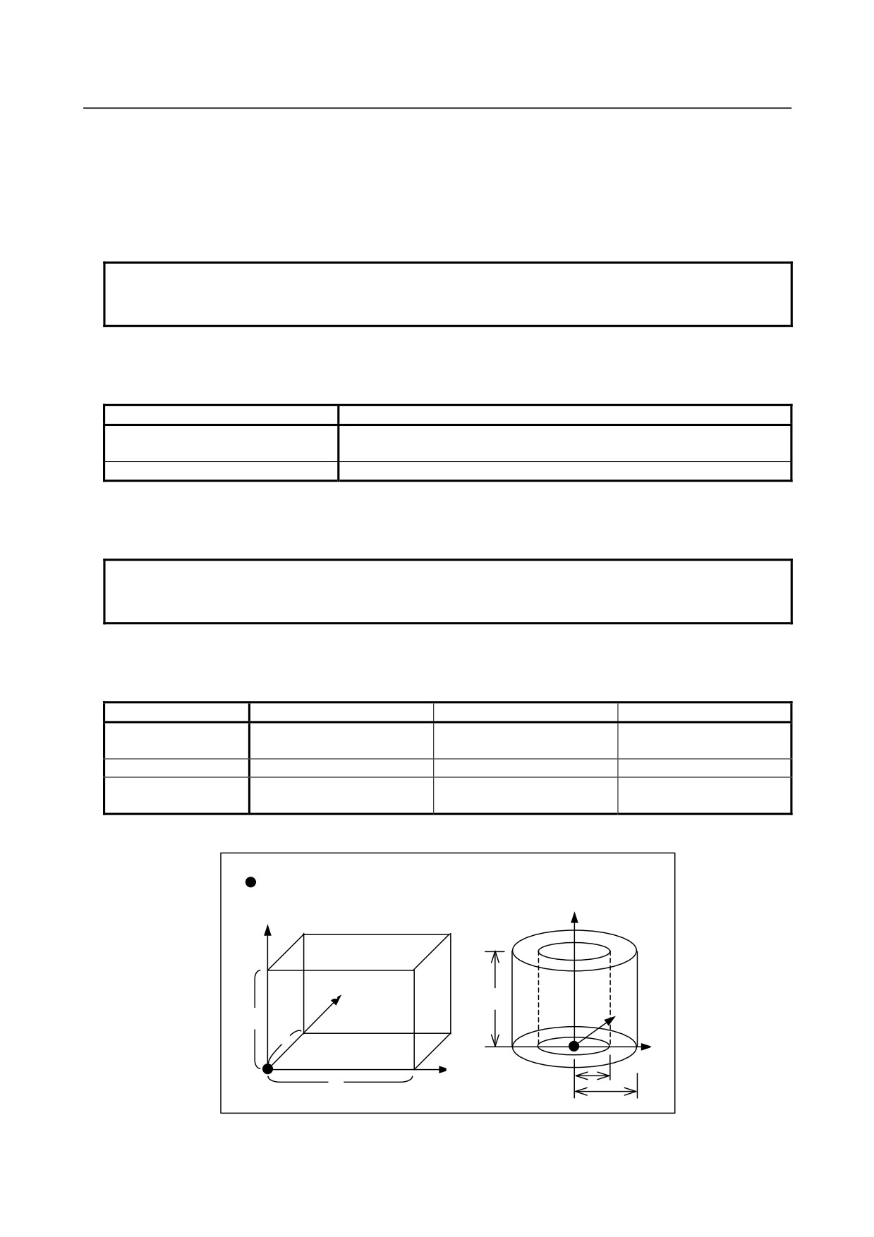
Select a type of blank figure from the following and set the corresponding value:
Setting
Figure
Column or cylinder
0
(parallel with the Z-axis)
1
Rectangular parallelepiped
Position (POSITION)
Set the reference position of a blank with coordinates (X,Y,Z) in the workpiece coordinate system.
NOTE
Set the reference position of a blank with coordinates (X,Y,Z) in the machine
coordinate system in case of bit 3 (BGM) of parameter No.11329=1.
Dimensions (DIMENSION)
Set the dimensions of each type of blank figure as indicated below.
Type of blank figure
Dimension I
Dimension J
Dimension K
Rectangular
Length in X-axis direction
Length in Y-axis direction
Length in Z-axis direction
parallelepiped
Column
Radius of column
0
Length of column
Radius of outer circle of
Radius of inner circle of
Cylinder
Length of cylinder
cylinder
cylinder
The relationship between the position and dimensions of a blank is shown below.
:Reference position(X,Y,Z)
Z
Z
Y
K
K
Y
J
X
X
J
I
I
- 726 -
B-64304EN/02
OPERATION
13.GRAPHIC FUNCTION
-
Tool figure (radius) (TOOL FIGURE (RADIUS))
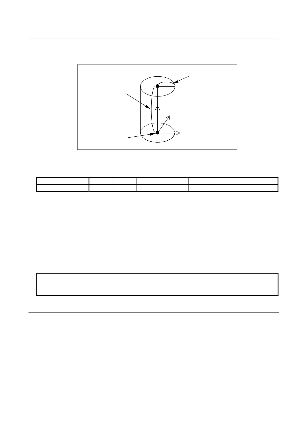
Set the radius of a tool figure to be drawn.
The tool length is the same as dimension K of a blank figure in the Z-axis direction.
Tool radius R
Tool length =
Blank dimension K
Z
Y
Programmed point
X
-
Graphic color
Set colors to be used for animation drawing.
The colors that can be set are indicated below together with their setting values:
Graphic color
White
Red
Green
Yellow
Blue
Purple
Light blue
Setting value
0
1
2
3
4
5
6
Blank
Set the color of a blank to be drawn in animation drawing.
Tool
Set the color of a tool to be drawn in animation drawing.
-
Tool length offset (Anime)
For animation drawing, whether to enable or disable the tool length offset can be selected.
Setting
0: The tool length offset is disabled for drawing.
1: The tool length offset is enabled for drawing.
NOTE
In animation drawing, the cutter radius compensation is always enabled for
drawing.
13.2.2.2 ANIMATION GRAPHIC (EXECUTION) screen
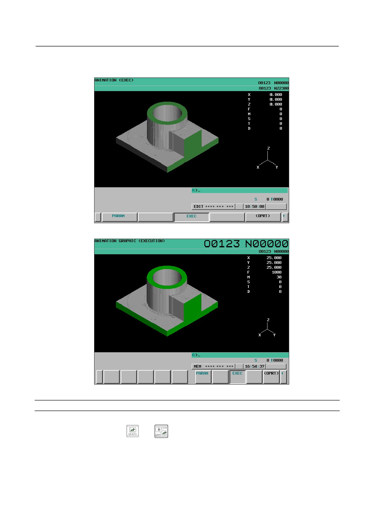
The ANIMATION GRAPHIC screen is used to draw a animation. The following operations can be
performed:
• Starting/ending animation drawing
• Rewind of a drawing target program
• Initializing a blank
• Enlarging/reducing/moving the graphic range
• Changing/rotating the graphic coordinate system
The screen configuration is as follows:
(1) Drawing area
(2) Status display of Background operation
(3) Program name and sequence number for drawing execution
(4) Current coordinates
- 727 -
13.GRAPHIC FUNCTION
OPERATION
B-64304EN/02
(5) Feedrate and M/S/T/D code instruction information
(6) Graphic coordinate system
Fig. 13.2.2.2 (a) ANIMATION GRAPHIC (EXECUTION) screen (8.4-inch LCD)
Fig. 13.2.2.2 (b) ANIMATION GRAPHIC (EXECUTION) screen (10.4-inch LCD)
ANIMATION GRAPHIC (EXECUTION) screen: Procedure
Procedure
1
Press the function key
(or
when a small MDI unit is used) to display the GRAPHIC
PARAMETER (DYNAMIC GRAPHIC) screen.
2
Press the [EXEC] soft key. The ANIMATION GRAPHIC (EXECUTION) screen is displayed.
- 728 -
B-64304EN/02
OPERATION
13.GRAPHIC FUNCTION
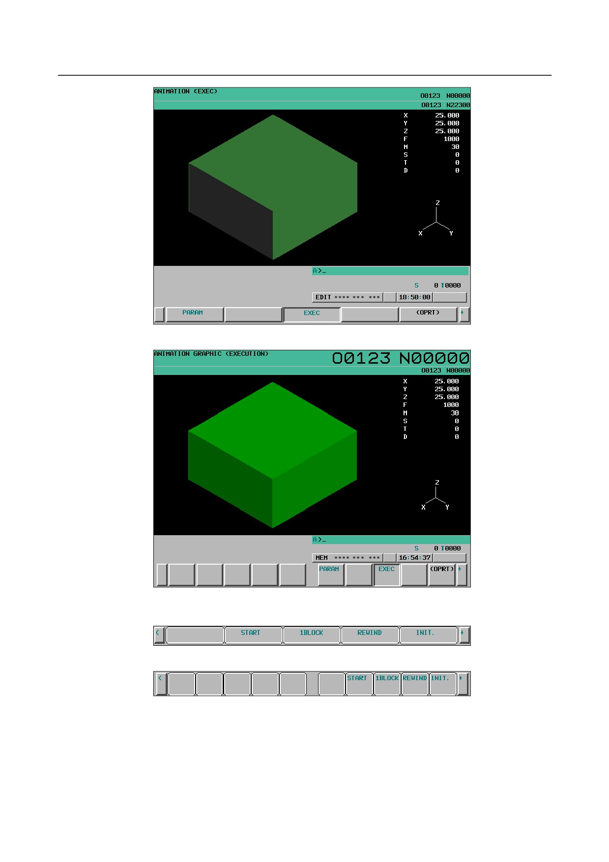
Fig. 13.2.2.2 (c) ANIMATION GRAPHIC (EXECUTION) screen (8.4-inch LCD)
Fig. 13.2.2.2 (d) ANIMATION GRAPHIC (EXECUTION) screen (10.4-inch LCD)
3
Press the [(OPRT)] soft key. The soft keys for tool path drawing are displayed.
Fig. 13.2.2.2 (e) ANIMATION GRAPHIC (EXECUTION) screen (operation) (8.4-inch LCD)
Fig. 13.2.2.2 (f) ANIMATION GRAPHIC (EXECUTION) screen (operation) (10.4-inch LCD)
- 729 -
13.GRAPHIC FUNCTION
OPERATION
B-64304EN/02
4
Press the continuous menu key
to display the soft keys for enlarging/reducing/moving the
graphic range.
Fig. 13.2.2.2 (g) ANIMATION GRAPHIC (EXECUTION) screen
(enlarging/reducing/moving the graphic range) (8.4-inch LCD)
Fig. 13.2.2.2 (h) ANIMATION GRAPHIC (EXECUTION) screen
(enlarging/reducing/moving the graphic range) (10.4-inch LCD)
5
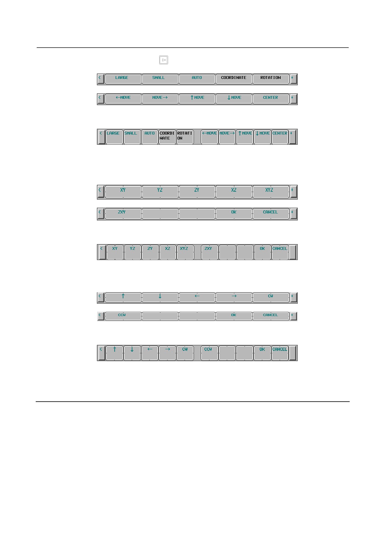
Press the [COORDINATE] soft key to display the soft keys for changing the graphic coordinate
system.
Fig. 13.2.2.2 (i) ANIMATION GRAPHIC (EXECUTION) screen
(changing the graphic coordinate system) (8.4-inch LCD)
Fig. 13.2.2.2 (j) ANIMATION GRAPHIC (EXECUTION) screen
(changing the graphic coordinate system) (10.4-inch LCD)
6
Press the [ROTATION] soft key to display the soft keys for rotating the graphic coordinate system.
Fig. 13.2.2.2 (k) ANIMATION GRAPHIC (EXECUTION) screen
(rotating the graphic coordinate system) (8.4-inch LCD)
Fig. 13.2.2.2 (l) ANIMATION GRAPHIC (EXECUTION) screen
(rotating the graphic coordinate system) (10.4-inch LCD)
For the operation of each soft key, see the explanation.
Explanation
The operations listed below are the same operations as for the PATH GRAPHIC (EXECUTION) screen.
See the explanation of the PATH GRAPHIC (EXECUTION) screen.
• Graphic program selection
• Starting / Stopping of drawing
• End of drawing
• Rewind of a drawing target program
-
Initializing a blank
Press the [INIT.] soft key to initialize and return a drawn machining profile to the original blank figure.
- 730 -

B-64304EN/02
OPERATION
13.GRAPHIC FUNCTION
NOTE
1 Blank initialization can also be performed by any of the following operations:
- Start of drawing
- Changing of the graphic coordinate system and graphic range by performing
enlargement/reduction/movement/rotation operations
- Change of screen
2 A machining profile once drawn for a blank is erased when the screen is
switched.
-
Enlarging/reducing the graphic range
The following soft keys displayed by step 4 are used:
•
[LARGE] soft key
This soft key increases the scale to enlarge the graphic range.
•
[SMALL] soft key
This soft key decreases the scale to reduce the graphic range.
•
[AUTO] soft key
When the blank figure specified in a graphic parameter is input, this soft key automatically scales the
graphic range so that the blank figure is contained within the graphic range.
If no blank figure is input, this soft key has no effect.
NOTE
Set the unit of scale for one enlargement/reduction operation in parameter No.
14713.
-
Moving the graphic range
The following soft keys displayed by step 4 are used:
•
[←MOVE] soft key
This soft key moves the graphic range to left.
•
[MOVE→] soft key
This soft key moves the graphic range to right.
•
[↑MOVE] soft key
This soft key moves the graphic range upward.
•
[↓MOVE] soft key
This soft key moves the graphic range downward.
•
[CENTER] soft key
This soft key returns the graphic range to the original position.
NOTE
1 Set the travel increment made by one horizontal move operation in parameter
No. 14714.
2 Set the travel increment made by one vertical move operation in parameter No.
14715.
-
Changing the graphic coordinate system
The following soft keys displayed by step 5 are used.
A graphic coordinate system selected here is the same one as set in the graphic parameter for the graphic
coordinate system.
•
[XY] soft key
This soft key selects the graphic coordinate system of XY (with a setting of 0).
•
[YZ] soft key
This soft key selects the graphic coordinate system of YZ (with a setting of 1).
- 731 -

13.GRAPHIC FUNCTION
OPERATION
B-64304EN/02
•
[ZY] soft key
This soft key selects the graphic coordinate system of ZY (with a setting of 2).
•
[XZ] soft key
This soft key selects the graphic coordinate system of XZ (with a setting of 3).
•
[XYZ] soft key
This soft key selects the graphic coordinate system of XYZ (with a setting of 4).
•
[ZXY] soft key
This soft key selects the graphic coordinate system of ZXY (with a setting of 5).
•
[OK] soft key
This soft key changes the current graphic coordinate system to the graphic coordinate system
selected by one of the soft keys above.
•
[CANCEL] soft key
This soft key cancels the graphic coordinate system selected by one of the soft keys above to return
to the original graphic coordinate system.
NOTE
The graphic coordinate system selected here is set in the graphic parameter for
the graphic coordinate system.
-
Rotating the graphic coordinate system
The following soft keys displayed by step 6 are used.
•
[↑] soft key
This soft key rotates the graphic coordinate system upward.
•
[↓] soft key
This soft key rotates the graphic coordinate system downward.
•
[←] soft key
This soft key rotates the graphic coordinate system to left.
•
[→] soft key
This soft key rotates the graphic coordinate system to right.
•
[CW] soft key
This soft key rotates the graphic coordinate system clockwise.
•
[CCW] soft key
This soft key rotates the graphic coordinate system counterclockwise.
•
[OK] soft key
This soft key changes the rotation angle of the current graphic coordinate system to the one set by
one of the soft keys above.
•
[CANCEL] soft key
This soft key cancels the rotation of the graphic coordinate system performed by one of the soft keys
above to return to the original graphic coordinate system.
NOTE
1 Set the travel increment made by one rotation operation in parameter No. 14716.
2 The rotation angle of the graphic coordinate system set here is not set in the
graphic parameter for rotation angle.
- 732 -
B-64304EN/02
OPERATION
13.GRAPHIC FUNCTION
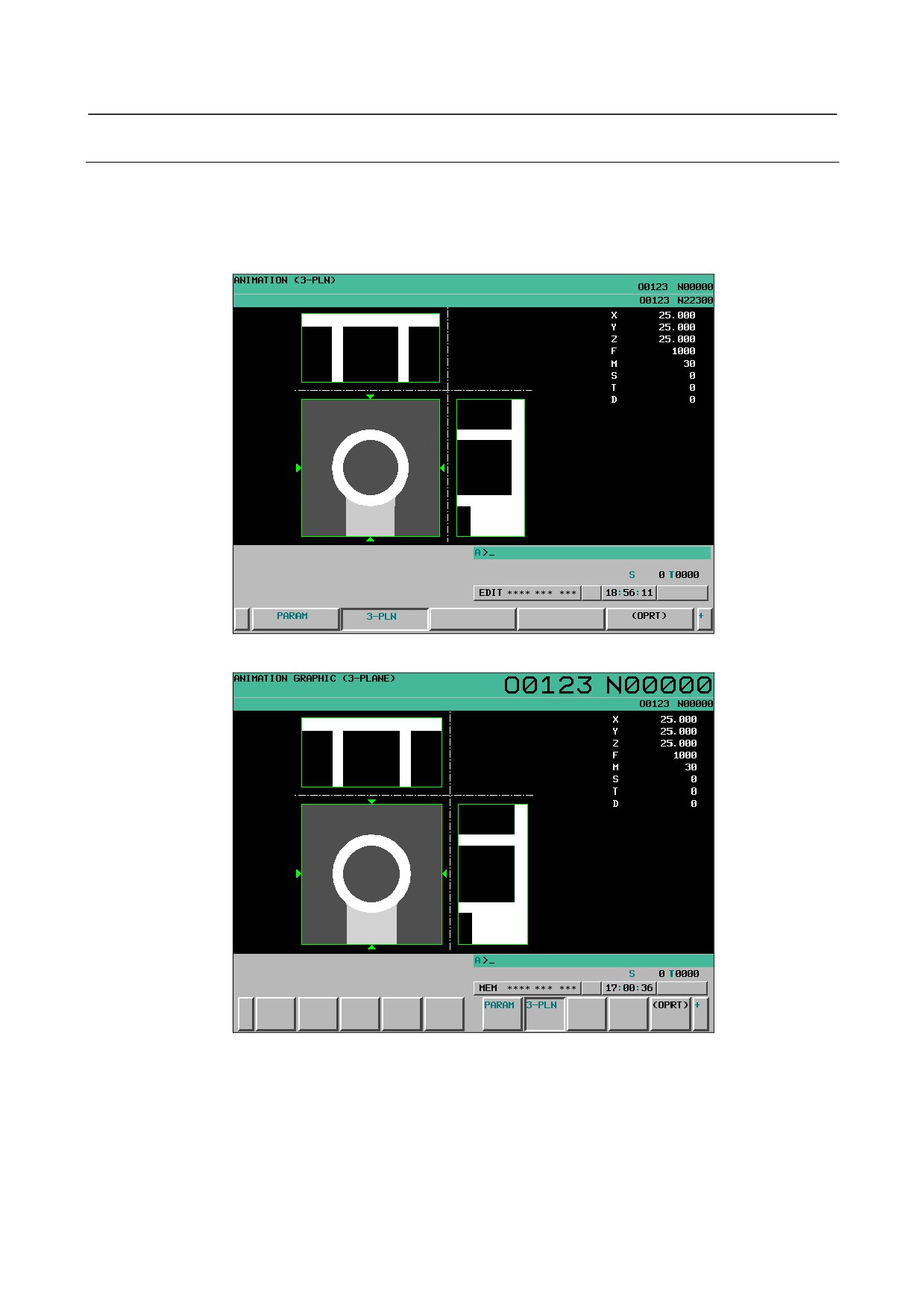
13.2.2.3 ANIMATION GRAPHIC (3-PLANE) screen
For a three-dimensional machining profile drawn on the ANIMATION GRAPHIC (EXECUTION) screen,
a three-plane diagram including one plan view and two side views can be drawn.
You can select one of four pairs of side view display positions. You can also arbitrarily change the
position of a cross section to be drawn in a side view.
Fig. 13.2.2.3 (a) ANIMATION GRAPHIC (3-PLANE) screen (8.4-inch LCD)
Fig. 13.2.2.3 (b) ANIMATION GRAPHIC (3-PLANE) screen (10.4-inch LCD)
- 733 -

13.GRAPHIC FUNCTION
OPERATION
B-64304EN/02
ANIMATION GRAPHIC (3-PLANE) screen: Procedure
Procedure
1
Press the function key
(or
when a small MDI unit is used) to display the ANIME
GRAPHIC (SETTING-1) screen.
If drawing is executed on the ANIMATION GRAPHIC (EXECUTION) screen before this operation,
machining profile is displayed.
If drawing is not executed on the ANIMATION GRAPHIC (EXECUTION) screen before this
operation, original blank figure is displayed.
2
Press the continuous menu key
3
Press the [3-PLN] soft key. The ANIMATION GRAPHIC (3-PLANE) screen is displayed.
Fig. 13.2.2.3 (c) ANIMATION GRAPHIC (3-PLANE) screen (8.4-inch LCD)
Fig. 13.2.2.3 (d) ANIMATION GRAPHIC (3-PLANE) screen (10.4-inch LCD)
- 734 -
B-64304EN/02
OPERATION
13.GRAPHIC FUNCTION
4
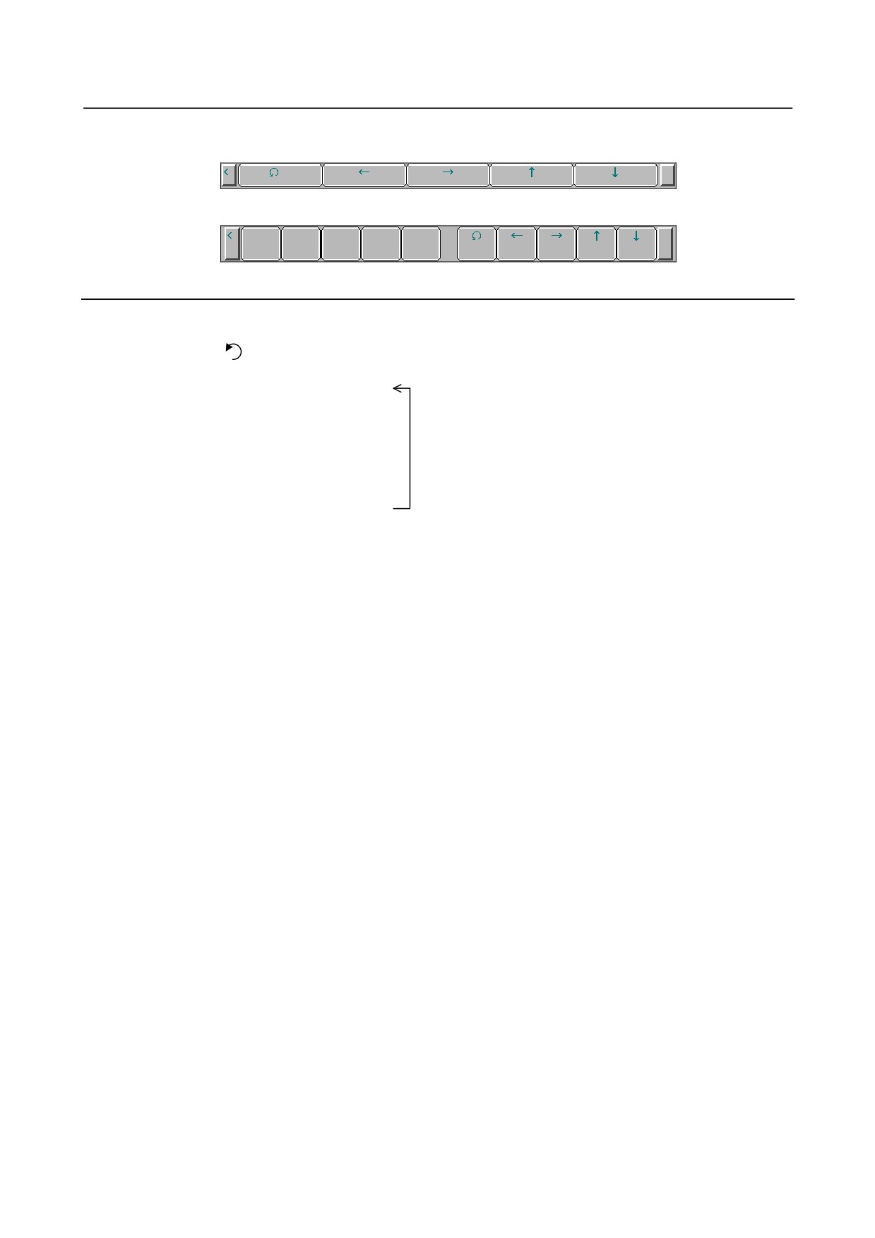
Press the [(OPRT)] soft key. The soft keys for three-plane diagram drawing are displayed.
Fig. 13.2.2.3 (e) ANIMATION GRAPHIC (3-PLANE) screen (three-plane diagram operation) (8.4-inch LCD)
Fig. 13.2.2.3 (f) ANIMATION GRAPHIC (3-PLANE) screen (three-plane diagram operation) (10.4-inch LCD)
Explanation
-
Switching the side view display
Use the soft key [
] displayed in step 4 to perform this operation.
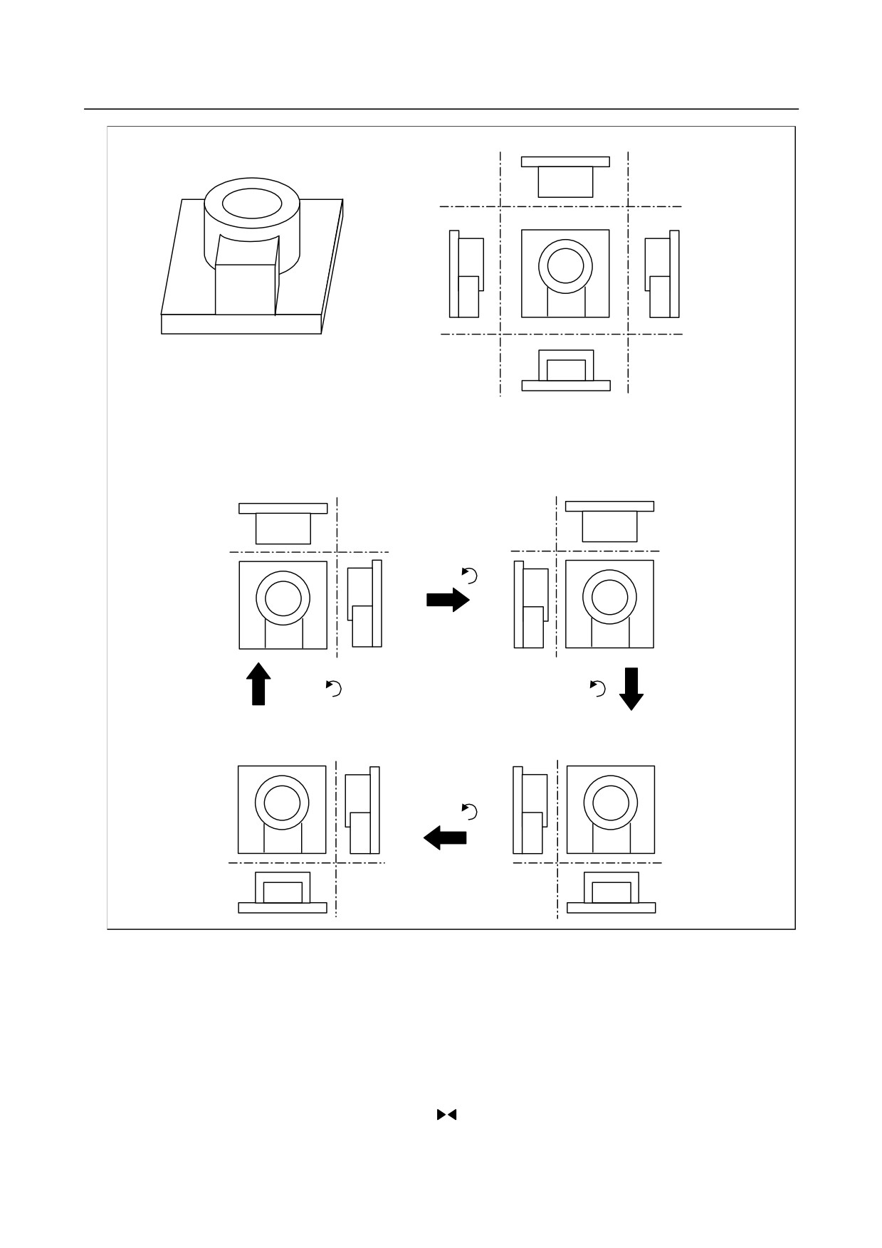
Each time you press the key, the side view display changes as shown below.
Display of the right and top side views
↓
Display of the top and left side views
↓
Display of the left and bottom side views
↓
Display of the bottom and right side views
- 735 -
13.GRAPHIC FUNCTION
OPERATION
B-64304EN/02
Top side view
Three-dimensional profile
Plan view
Left side
Right side
view
view
Bottom side view
The side view positions on the right figure above are changed as shown below.
Display of the right and top side views
Display of the top and left side views
Press [
].
Press [
].
Press [
].
Display of the bottom and right side views
Display of the left and bottom side views
Press [
].
Fig. 13.2.2.3 (g) Display example of three-plane diagram drawing
-
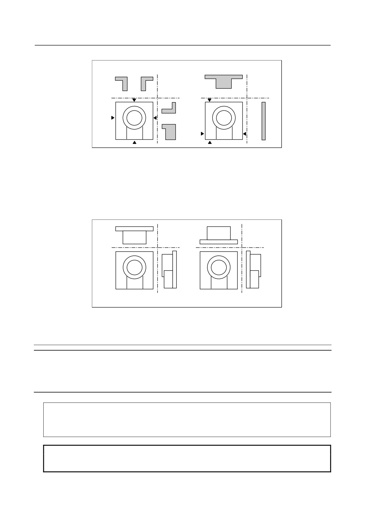
Changing the position of a cross section in a side view
Use the following soft keys displayed in step 4 or the MDI cursor keys to specify the position of a cross
section in a side view.
• Soft keys [←] and [→], cursor keys [←] and [→]
Use these keys to horizontally move the marks ▲▼ that indicate the position of a cross section in a
left or right side view.
• Soft keys [↑] and [↓], cursor keys [↑] and [↓]
Use these keys to vertically move the marks
that indicate the position of a cross section in a top
or bottom side view.
After the above operation, a cross section at the marked position is drawn in a side view.
- 736 -
B-64304EN/02
OPERATION
13.GRAPHIC FUNCTION
Example 1
Example 2
Fig. 13.2.2.3 (h) Display example of cross section position
You can change the cross section position continuously by holding down any of the MDI cursor keys.
The amount of change of the cross section position can be modified in the range of 1 to 10 dots by setting
parameter No. 6515.
-
Method of drawing a three-plane diagram
You can select one of the following methods of drawing a three-plane diagram by setting bit 2 (3PL) of
parameter No. 6501.
Third angle projection (3PL = 0)
First angle projection
(3PL = 1)
Fig. 13.2.2.3 (i) Selection of method of drawing three-plane diagram
13.2.2.4 Programmable Data Input (G10) for Blank Figure Drawing
Parameters
Overview
For animation drawing by the dynamic graphic display function, a programmable data input (G10)
command can be used to set the graphic parameters for the blank figure (figure/position/dimensions) in an
NC program.
Format
G10 L90 P_ IP_ I_ J_ K_ ;
P_
: Blank figure
IP_
: Addresses of the basic three axes and the reference position of a blank
I_,J_,K_ : Dimensions of a blank
NOTE
1 This command is valid only during animation drawing. It is ignored during normal
automatic operation.
- 737 -
13.GRAPHIC FUNCTION
OPERATION
B-64304EN/02
NOTE
2 This command is a one-shot G code.
3 This command must be specified in a single block.
Explanation
-
Blank figure (P_)
Specify the type of a blank figure with either of the following settings for shapes.
Setting
Figure
Column or cylinder
0
(parallel with the Z-axis)
1
Rectangular parallelepiped
The specified value is set in parameter No. 11343.
-
Reference position of a blank (IP_)
Specify the reference position of a blank with coordinates (X,Y,Z) in the workpiece coordinate system.
NOTE
Specify the reference position of a blank with coordinates (X,Y,Z) in the machine
coordinate system in case of bit 3 (BGM) of parameter No.11329=1.
The specified value is set in parameter No. 11344.
-
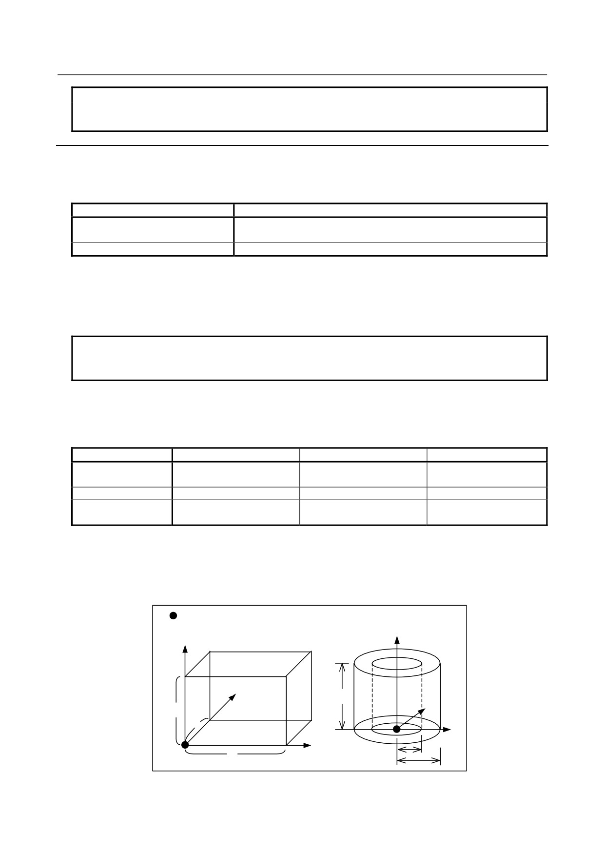
Dimensions of a blank (I_,J_,K_)
For the shape of each blank, specify the dimensions of the blank as follows:
Blank figure
Address I
Address J
Address K
Rectangular
Length in X-axis direction
Length in Y-axis direction
Length in Z-axis direction
parallelepiped
Column
Radius of column
0
Length of column
Radius of outer circle of
Radius of inner circle of
Cylinder
Length of cylinder
cylinder
cylinder
The specified value are set in parameter No.11345 (address I), parameter No.11346 (address J), and
parameter No.11347 (address K).
-
Relationship between the position and dimensions of a blank
The relationship between the position and dimensions of a blank is shown in the figure below.
:Reference position (X,Y,Z)
Z
Z
Y
K
K
Y
J
X
X
J
I
I
- 738 -
B-64304EN/02
OPERATION
13.GRAPHIC FUNCTION
-
Operation to be performed when this command is issued
When this command is executed in the animation drawing operation, the specified values are set in the
drawing parameters for the blank figure, reference position, and dimensions that correspond to the
specified arguments, and the drawing area is automatically set again with the values set.
This causes this command and subsequent commands to perform drawing in the new drawing area.
NOTE
When this command is executed, the following occurs for drawing that has been
previously performed.
The command should therefore be executed at the beginning of a program for
drawing.
- The blank figure is initialized.
- The tool figure is erased.
Therefore, be sure to set the radius value of the tool again with G10L91
command (Refer to the next section) after G10L90 is instructed.
- The drawing start position is made invalid.
13.2.2.5 Programmable Data Input (G10) for Tool Figure Drawing
Parameters
Overview
For animation drawing by the dynamic graphic display function, a programmable data input (G10)
command can be used to set the graphic parameter for the tool figure (radius) in an NC program.
Format
G10 L91 R_ ;
R_ : Tool radius
NOTE
1 This command is valid only during animation drawing. It is ignored during normal
automatic operation.
2 This command is a one-shot G code.
3 This command must be specified in a single block.
Explanation
-
Tool radius (R_)
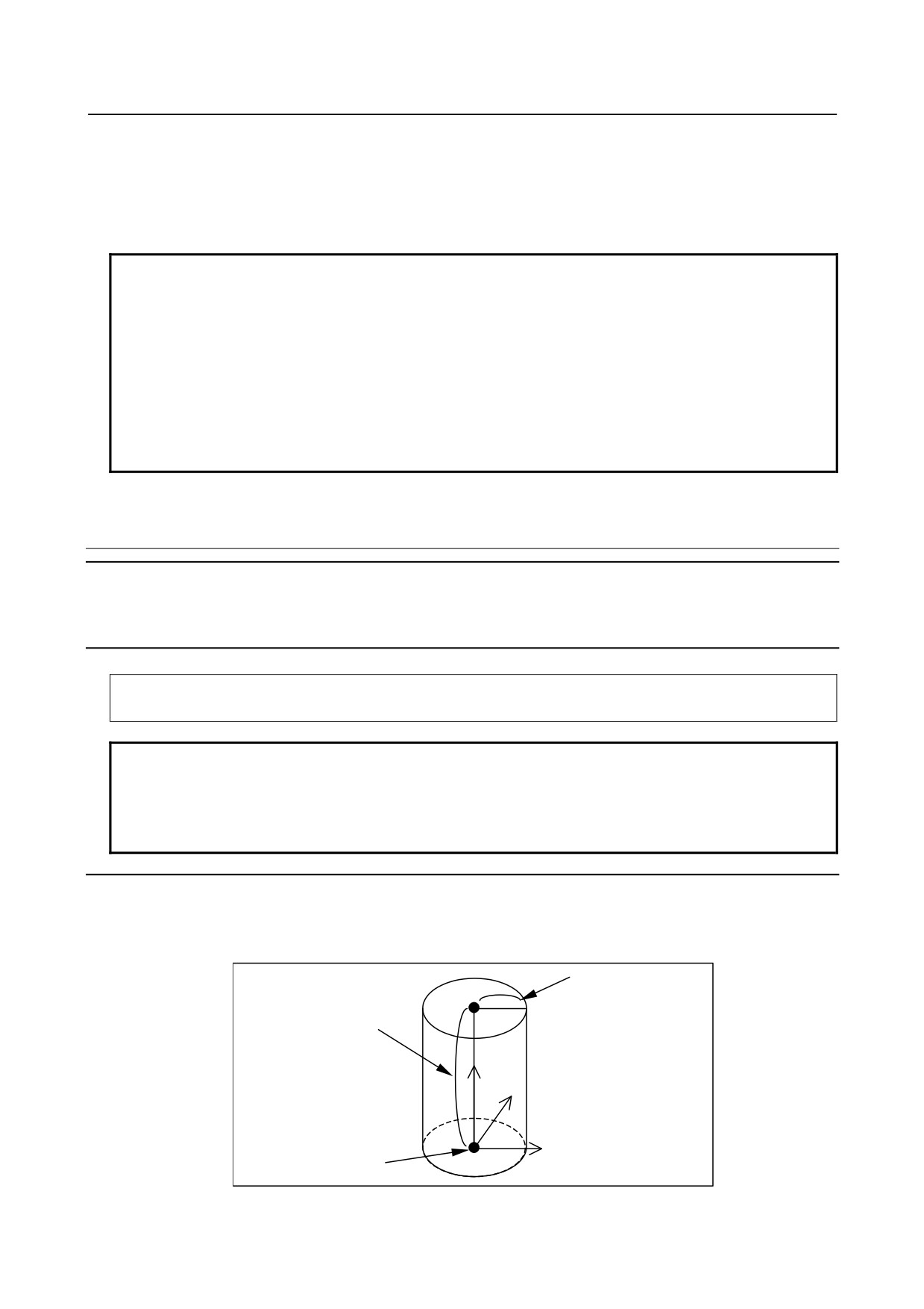
Set the radius of a tool figure to be drawn.
The tool length is the same as dimension K of a blank figure in the Z-axis direction.
Tool radius R
Tool length =
Blank dimension K
Z
Y
Programmed point
X
- 739 -
13.GRAPHIC FUNCTION
OPERATION
B-64304EN/02
-
Operation to be performed when this command is issued
When this command is executed in the animation drawing operation, the specified value is set in the
graphic parameter for the tool figure (radius) that corresponds to the specified argument, and the tool
figure is redrawn with the set value.
NOTE
When this command is executed, the following occurs for drawing that has been
previously performed.
-
The blank figure is updated.
13.2.3 Warning Messages
Warning message
Content
START REJECTED
This program cannot be drawn.
NO PROGRAM SELECTED
No drawing target program is selected.
UNAVAILABLE COMMAND IS IN DRAWING
An NC statement/macro statement that can not execute
drawing is instructed.
ILLEGAL SETTING OF GRAPHIC PARAMETERS
Graphic parameters are not set correctly.
13.2.4 Note
NOTE
1 The drawing target axes are the basic three axes.
The basic three axes are the X-axis, Y-axis, and Z-axis on the basic coordinate
system set with parameter No.1022.
2 In a drawing program having a sequence of contiguous small blocks, drawing
requires longer processing time, possibly causing machining time to become
longer than actual machining time.
- 740 -
B-64304EN/02
OPERATION
13.GRAPHIC FUNCTION
NOTE
3
When drawing is executed, data is treated as described below.
(1) Parameters
The same parameters as for automatic operation are used. However,
parameters cannot be rewritten with a command such as the G10 command.
If an attempt is made to rewrite a parameter with programmable parameter
input (G10L52), the command is ignored.
However, by setting bit 7 (GST) of parameter No.11329, drawing can be
temporarily stopped with the warning "UNAVAILABLE COMMAND IS IN
DRAWING".
(2) Tool compensation value/workpiece origin offset/extended workpiece origin
offset/macro variable, etc.
For each of drawing execution and automatic operation, separate data is
used. At the start of drawing, data for drawing is produced by copying data
for automatic operation. In subsequent operations, the data for drawing and
the data for automatic operation are treated independently of each other.
So, even if data is rewritten with a command such as G10, drawing execution
and automatic operation do not affect each other. Note, however, that data
rewritten in drawing execution is not reflected in the data for automatic
operation but is deleted.
(3) Tool life management data
These data items are not used for drawing execution. So, if an attempt is
made to rewrite data with G10, the command is ignored.
However, by setting bit 7 (GST) of parameter No.11329, drawing can be
temporarily stopped with the warning "UNAVAILABLE COMMAND IS IN
DRAWING".
13.2.5 Restrictions
-
Functions that operate differently in drawing execution and automatic
operation
The operations of the following functions in drawing execution differ from the operations in automatic
operation:
1.
Operations that differ, depending on the custom macro
1)
Interface signal
#1000 to #1035 are assumed to be 0 at all times.
2)
Message output
A message to be output with #3006 is not displayed but is ignored.
3)
clock
#3001 and #3002 are ignored. So, note that drawing is not continued, for example, if the
following is specified:
#3001=0 ;
WHILE [#3001 LE 100] DO1 ;
END1 ;
4)
Mirror image
#3007 is assumed to be 0 at all times.
5)
Program-restarted state
#3008 is assumed to be 0 at all times.
6)
External output command
BPRNT, DPRNT, POPEN, and PCLOS are ignored.
- 741 -
13.GRAPHIC FUNCTION
OPERATION
B-64304EN/02
2
Functions that perform partly different operations
1)
When G28 (automatic reference position return) is specified, up to the intermediate point is
drawn.
2)
When G29 (automatic return from the reference position) is specified, drawing is performed
from the intermediate point.
3)
When G27 (reference position return check) is specified, no reference position return check is
made.
4)
No stored stroke limit check is made.
5)
When G31 (skip function), or G31.1, G31.2, or G31.3 (multistage skip function) is specified,
drawing is performed up to the specified position, regardless of the skip signal.
6)
When G60 (single direction positioning) is specified, drawing is performed directly up to the
specified position at all times even if the positioning direction is opposite.
3.
Functions that perform different operations
If the following functions are specified, the operations described below result:
1) G07.1 (cylindrical interpolation)
Linear interpolation is performed only with linear axes.
-
Functions that do not support drawing
The following functions are ignored in drawing execution:
1)
G04 (dwell)
2)
G20, G21 (inch/metric switch)
3)
Auxiliary function (M, S, T, B)
4)
G22, G23 (stored stroke limit check on/off)
5)
G10 (programmable data input for other than the graphic parameters for the blank figure/tool figure)
NOTE
If G10 (programmable data input) is specified, drawing can be temporarily
stopped with the warning "UNAVAILABLE COMMAND IS IN DRAWING" by
setting bit 7 (GST) of parameter No.11329.
The following functions are warning in drawing execution:
1) M198 (external subprogram call)
-
Functions that support drawing
The operations performed with the following program commands can be drawn:
1) G00 (Positioning)
2) G01 (Linear interpolation)
3) G02/G03 (Circular interpolation)
However, helical interpolation with the instruction axis other than basic three axes cannot be drawn.
4) G17/G18/G19 (Plane selection)
5) G33 (Threading)
However, it is drawn as linear interpolation.
6) G40/G41/G42 (Cutter compensation/cancel)
7) G52 (Local coordinate system)
8) G53 (Machine coordinate system selection)
9)
G54 to G59 (Workpiece coordinate system selection)
10) G54.1 (Extended workpiece coordinate system selection)
11) G65 (Macro call)
12) G68/G69 (Coordinate system rotation/cancel)
13) G90/G91 (Absolute/incremental command)
14) G92 (Workpiece coordinate system change)
15) G92.1 (Workpiece coordinate system preset)
16) G94/G95 (Feed per minute/Feed per rotation)
- 742 -
B-64304EN/02
OPERATION
13.GRAPHIC FUNCTION
17) G96/G97 (Constant surface speed control/cancel)
18) M98 (Subprogram call)
19) G73/G74/G76/G81/G82/G83/G84/G85/G86/G87/G88/G89/G80
(Canned cycle for drilling)
NOTE
1 It is possible to draw with the G68 (Coordinate system rotation) instruction only
in the tool path drawing.
And, the display of coordinates when instructing in G68 is a coordinate value on
the workpiece coordinate system.
2 In animation drawing, shape by the movement of back boring cycle command is
different from actual shape.
3 In animation drawing, movement to shift amount at the bottom of a hole in the
fine boring cycle and back boring cycle command is not drawn by setting bit 1
(ABC) of parameter No.11349=0.
-
Operations that do not support drawing
The following operations cannot be drawn:
1)
Backward movement based on the retrace function
2)
Forward movement/backward movement/resumed forward movement based on the manual handle
retrace function
3)
Movement made with skip signal input for a skip command or multistage skip command
4)
Movement on an axis based on PMC axis control
5)
Operation based on manual interrupt, manual handle interrupt, etc.
6)
Operation based on the high-speed, high-precision function (AI advanced preview control, AI
contour control, AI contour control II)
-
Drawing start position
In tool path drawing, if G92, G52, or G92.1 is specified at the start of a drawing target program, the
position specified with the G code is the drawing start position. If none of these G codes is specified,
the end point of the first moving command is the drawing start position.
In animation drawing, the current position when the tool figure is displayed is the drawing start position.
If the value where to be drawn is absolute coordinate value (bit 3 (BGM) of parameter No.11329=0), the
origin setting by modal coordinate system command (work coordinate system and local coordinate
system) on the automatic operation side is not reflected in the value where to be drawn.
-
Use of this function with other functions
When this function is specified, the following functions cannot be used:
• Graphic display
• MANUAL GUIDE i
-
VGA display based on the C language executor
If VGA display based on the C language executor is used, the VGA window is erased when the screen
display is switched to a screen of this function.
So, when using the VGA window, determine the screen of this function by screen number and close the
VGA window before switching the screen display.
-
Use of the CNC screen display function
The following restriction exists when the screen of dynamic graphic display function is displayed by the
CNC screen display function.
1) The drawing screen is not displayed in the CNC screen display function by way of via embedded
Ethernet. Please use the CNC screen display function by way of the FAST Ethernet board.
2) The drawing screen is not displayed in the CNC screen dual display function.
- 743 -
13.GRAPHIC FUNCTION
OPERATION
B-64304EN/02
3)
Please do not start / shut down the CNC screen display function when you display the drawing
screen. Please start / shut down the CNC screen display function after it switches to other screens.
-
Use of the Screen hard copy function
Drawing is temporarily stopped when the drawing screen is copied with the screen hard copy function.
The drawing can be restarted by pushing [RESTART] soft key if necessary after the copy operation is
finished.
13.3 DYNAMIC GRAPHIC DISPLAY (T SERIES)
Overview
The dynamic graphic display function enables the display of a machining travel path without actually
running the machine.
With the dynamic graphic display function, the machine need not be actually run as with the graphic
display function. Before starting path drawing, however, you should select MEM mode by the mode
switch on the machine operator's panel and set conditions that can be used to start actual NC operation of
the machine.
13.3.1 Graphic Parameter Screen
The graphic parameter screen used to make necessary settings for tool path drawing and the methods of
making these settings are the same as those for the graphic display function.
See Section 13.1, "GRAPHIC DISPLAY".
13.3.2 Path Drawing
Explanation
The PATH GRAPHIC screen is used to draw a tool path. The following operations can be performed:
• Starting/ending tool path drawing
• Rewinding a drawing target machining program
• Erasing a drawn tool path
• Enlarging/reducing the graphic range
Procedure for drawing a path on the path graphic screen
To draw a tool path, select MEM mode by the mode switch on the machine operator's panel and set
conditions that can be used to start actual NC operation of the machine.
Then, use the following procedure to perform drawing.
Procedure
1
Press the function key
(or
when a small MDI unit is used) and set necessary graphic
parameters on the GRAPHIC PARAMETER screen.
2
Press the [PATH EXEC] soft key. The PATH GRAPHIC screen is displayed.
3
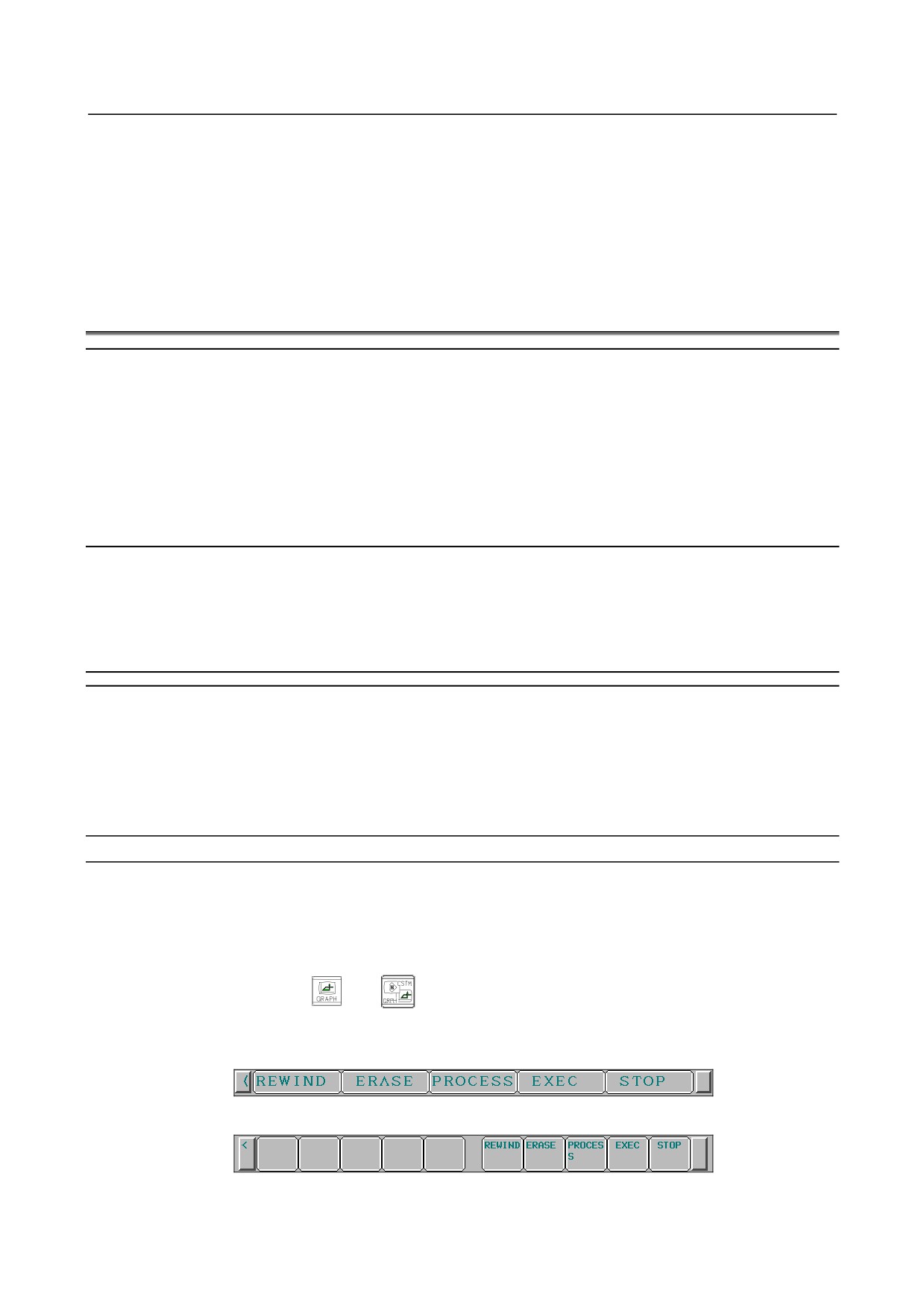
Press the [(OPRT)] soft key. The soft keys for tool path drawing are displayed.
Fig. 13.3.2 (a) PATH GRAPHIC (EXECUTION) screen (operation) (8.4-inch LCD)
Fig. 13.3.2 (b) PATH GRAPHIC (EXECUTION) screen (operation) (10.4-inch LCD)
- 744 -
B-64304EN/02
OPERATION
13.GRAPHIC FUNCTION
NOTE
A travel path cannot be drawn if axis movement is disabled due to the start lock
or interlock state. Release the lock state before starting drawing.
-
Starting drawing
•
[EXEC] soft key
Drawing is performed continuously until the M02 or M30 block in the program is reached.
When the single block switch on the machine operator's panel is turned on and drawing is started, a
single block stop operation is performed after drawing only for a single block.
•
[PROCESS] soft key
If drawing is started by pressing the [PROCESS] soft key, a single block stop operation is performed
at the M00 or M01 block in the machining program when that block is executed.
To restart the drawing, press the [EXEC] or [PROCESS] soft key again.
-
Stopping drawing
•
[STOP] soft key
During drawing started by pressing the [EXEC] or [PROCESS] soft key, a single block stop
operation can be performed by pressing the [STOP] soft key.
To restart the drawing, press the [EXEC] or [PROCESS] soft key again.
-
Erasing a drawn tool path
•
[ERASE] soft key
A drawn path can be erased by pressing the [ERASE] soft key.
-
Rewind of a drawing target program
•
[REWIND] soft key
The machining program can be rewound by pressing the [REWIND] soft key.
This soft key is enabled when drawing is stopped.
Procedure for enlarging or reducing a drawn path on the path graphic screen
On the tool path graphic screen, you can move the center position of the tool path drawing or enlarge or
reduce the tool path drawing while viewing the drawn tool path.
If any of these operations is executed, the tool path already drawn is cleared.
Procedure
1
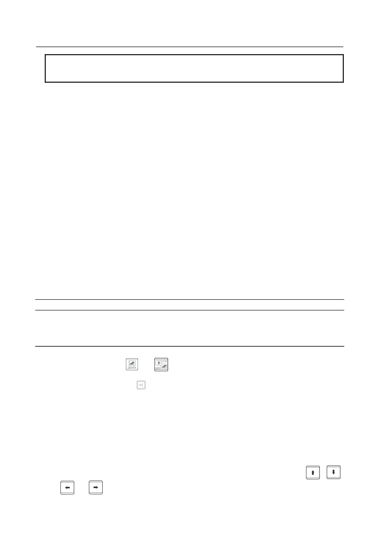
Press the function key
(or
when a small MDI unit is used).
2
Press the [GRAPH] soft key to display the PATH GRAPHIC screen, and then draw a tool path.
3
Press the return menu key
4
Press the [LARGE] soft key.
-
Procedure for changing the graphic range by setting a graphic center and
magnification
The graphic center position can be moved. At the same time, the scale can also be changed. So, the
tool path can be enlarged or reduced at a desired new center position.
5
After step 4 described above, press the [CENTER] soft key.
A yellow cursor appears at the center of the screen, and the soft key display is changed.
6
Move the yellow cursor to a new graphic center position by using the cursor key
,
,
, or
- 745 -
13.GRAPHIC FUNCTION
OPERATION
B-64304EN/02
7
When changing the scale, key in a value from 0.01 to 100 (magnification) then press the [INPUT]
soft key. An input value is displayed at "SCALE" in the lower-right corner of the screen.
When you press the [+INPUT] soft key, the current magnification is incremented by an input value.
8
Press the [EXEC] soft key to end the operation.
After this step, the setting made in the above steps is effective to enable drawing in the new graphic
range.
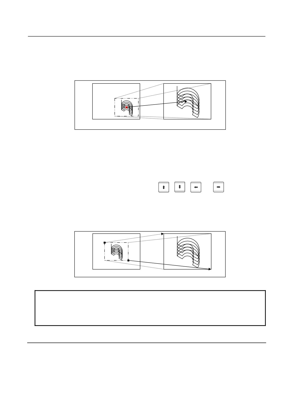
Before graphic movement
After graphic movement
Fig. 13.3.2 (c) Graphic movement (magnification = 2.00)
-
Procedure for changing the graphic range with a rectangle
A tool path can be drawn by enlarging a specified rectangular area.
5
After step 4 described above, press the [AREA] soft key.
Two cursors, one in red and the other in yellow, appear at the center of the screen, and the soft key
display is changed.
6
Move the yellow cursor by using the cursor key
,
,
, or
. The cursor to be
moved can be switched by pressing the [HI/LO] soft key.
Move the two cursors to the diagonal points of a new rectangular graphic range. A tool path is
drawn next time so that the drawn tool path is contained in this rectangular range.
7
Press the [EXEC] soft key to end the operation.
After this step, the setting made in the above steps is effective to enable drawing in the new graphic
range.
Before graphic enlargement
After graphic enlargement
Fig. 13.3.2 (d) Graphic enlargement
NOTE
1 To stop an enlargement/reduction operation, press the [CANCEL] soft key.
2 Even if you perform an enlargement/reduction operation, the tool path already
drawn on the screen is neither moved nor enlarged. The enlargement/reduction
setting is effective next time drawing is performed.
13.3.3 Restrictions
-
Tool registration command in the tool life management function
During drawing, tool registration (G10L3 command) in the tool life management function is disabled.
You can therefore use the G10L3 command to register a new tool only during normal automatic
operation.
- 746 -
B-64304EN/02
OPERATION
14.VIRTUAL MDI KEY FUNCTION
14 VIRTUAL MDI KEY FUNCTION
Chapter 14, "VIRTUAL MDI KEY FUNCTION", consists of the following sections:
14.1 VIRTUAL MDI KEY
747
14.1 VIRTUAL MDI KEY
Overview
This function is used to perform program editing and changing of various data using the keyboard
displayed on the LCD with a touch panel.
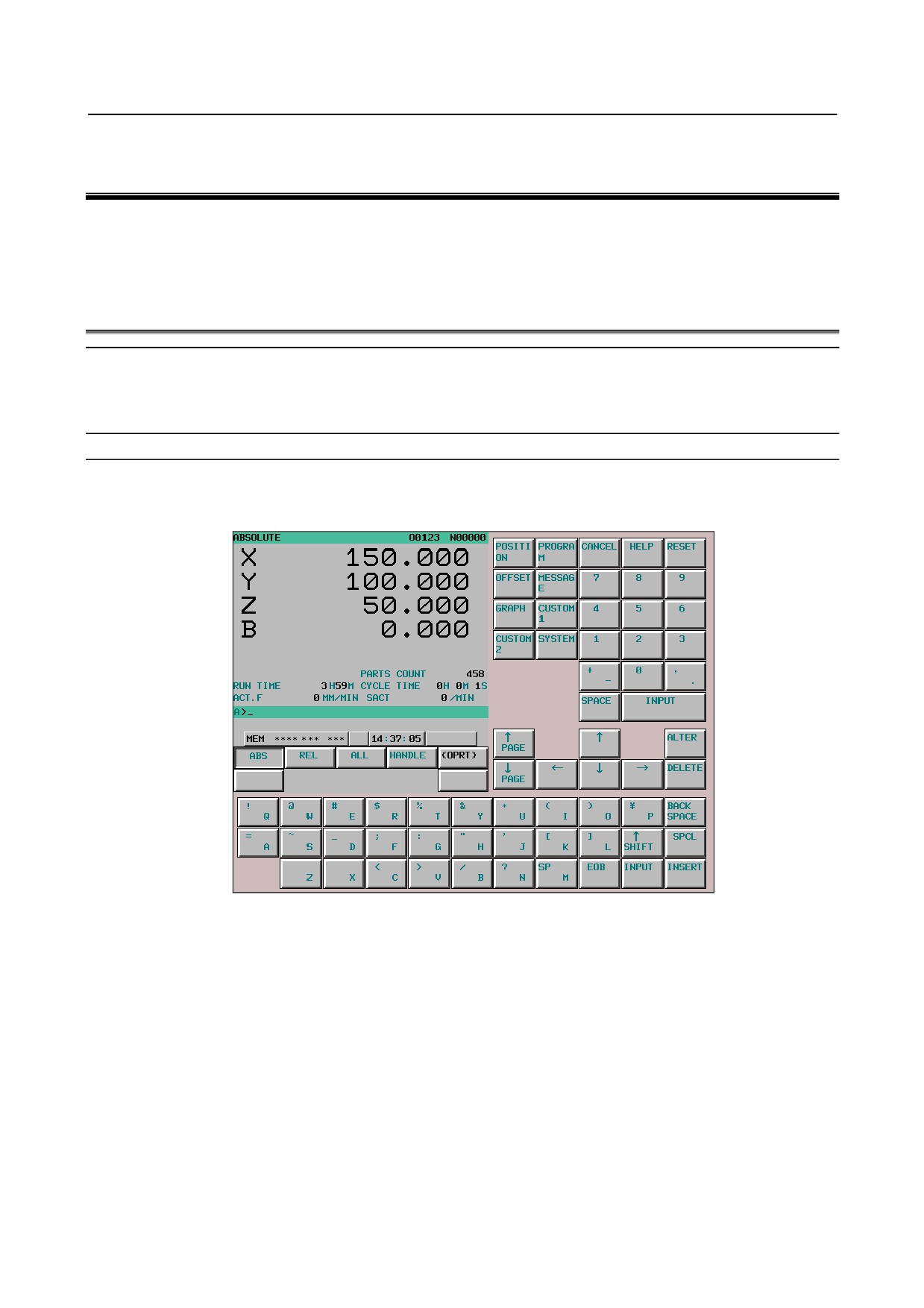
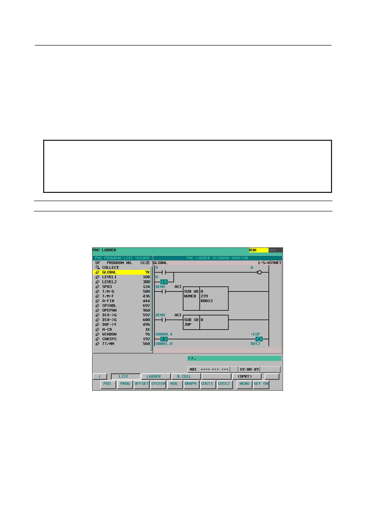
Screen on which a CNC screen is displayed in the upper left 1/4 area
Explanation
A CNC screen equivalent to that displayed on 8.4-inch LCD is displayed in the upper left area of the
screen, and the keyboard is displayed in the remaining area.
Figure 14.1 (a) Screen on which a CNC screen is displayed in the upper left area
Operation
-
Input key
The display "INPUT" on the virtual MDI keyboard is equivalent to the input key.
-
Cancel key
The displays "BACK SPACE" and "CANCEL" on the virtual MDI keyboard are equivalent to the cancel
key.
-
Shift key
The display "↑ SHIFT" on the virtual MDI keyboard is equivalent to the shift key.
Pressing the "↑ SHIFT" key once places the system in the shift state, and pressing the "↑ SHIFT" key
again or another key releases the system from the state.
Pressing a key in the shift state causes the character indicated in the upper left corner of the key to be
entered.
- 747 -
14.VIRTUAL MDI KEY FUNCTION
OPERATION
B-64304EN/02
-
Simultaneous pressing of two keys
The operation to be performed for pressing two key simultaneously, such as the "CANCEL" and
"RESET" keys to erase alarm SW0100, is as follows:
(1) Press the "SPCL" key. The "SPCL" key is held down, and places the system in SPCL mode.
(2) Press the keys to be pressed simultaneously, one at a time.
(3) Press the "INPUT" key. Of the keys pressed in SPCL mode, the last two are assumed to have been
pressed simultaneously. The system is released from SPCL mode, and the SPCL key, which has
been held down, returns to the normal state.
Example: "SPCL" → "CANCEL" → "RESET" → "INPUT"
NOTE
1 In SPCL mode, other keys are disabled until the "SPCL" or "INPUT" key is
pressed.
2 Pressing the "SPCL" key in "SPCL" mode causes all keys pressed in SPCL
mode to be disabled. The system is released from SPCL mode, and the SPCL
key, which has been held down, returns to the normal state.
Screen on which a CNC screen is displayed in the entire area
Explanation
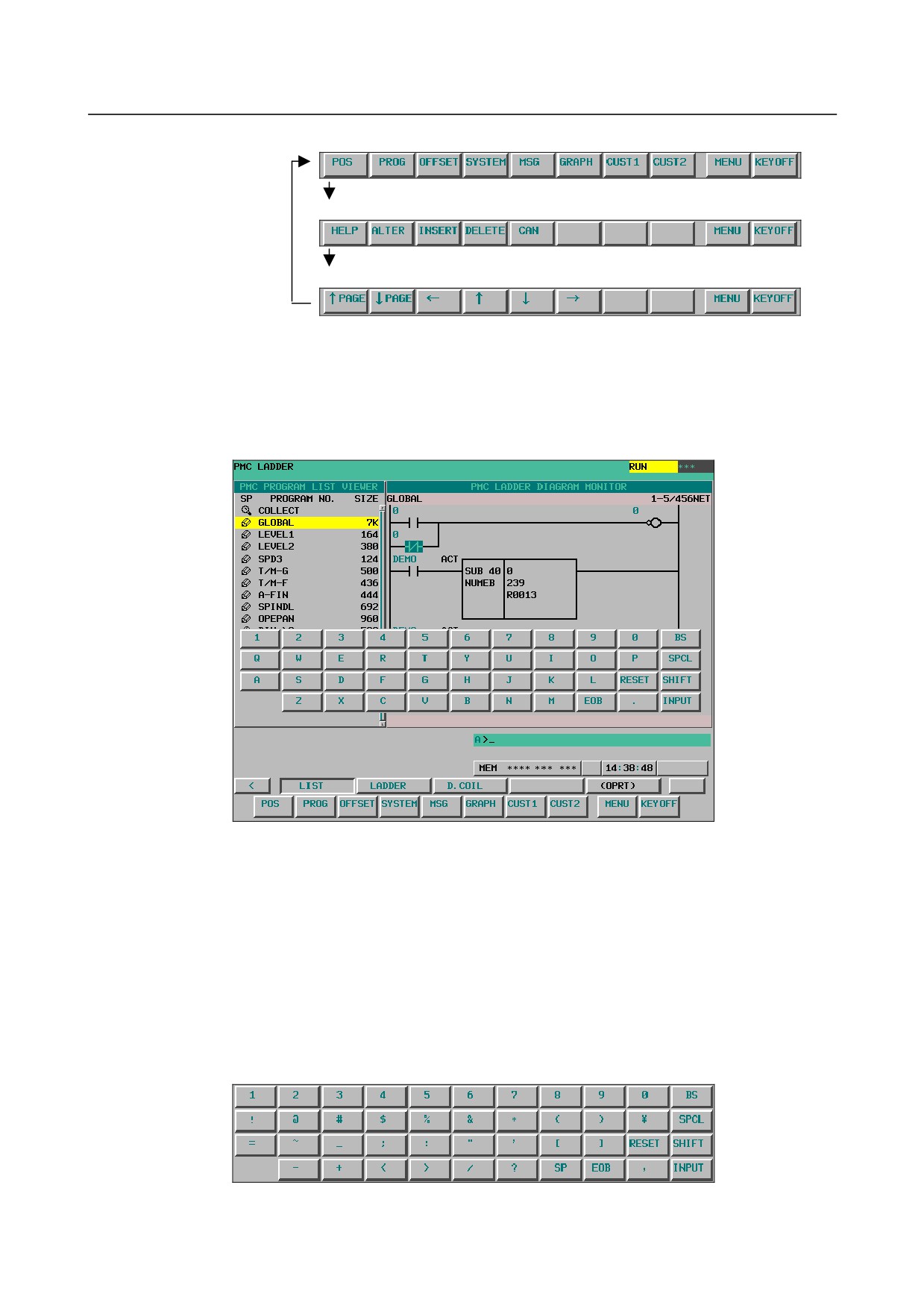
A CNC screen equivalent to that displayed on 8.4-inch LCD is displayed in the entire area. Function keys
and the ON/OFF button for virtual keys are displayed at the bottom of the screen.
Figure 14.1 (b) Screen on which a CNC screen is displayed in the entire area
Operation
-
Function key page switching
Pressing "MENU" located near the lower right corner of the screen switches the screen to page 1, page 2,
page 3, and back to page 1 in this order.
- 748 -
B-64304EN/02
OPERATION
14.VIRTUAL MDI KEY FUNCTION
Function keys on page 1
Function keys on page 2
Function keys on page 3
-
Display of virtual keys
Pressing "KEY ON" located at the lower right corner of the screen displays virtual MDI keys. The
character string on the key top changes to "KEYOFF".
Pressing "KEYOFF" hides virtual MDI keys.
Figure 14.1 (c) State in which virtual keys are ON
-
Input key
The display "INPUT" on the virtual MDI keyboard is equivalent to the input key.
-
Cancel key
The displays "BS" on the virtual MDI keyboard are equivalent to the cancel key.
(The function key
"CAN" is also equivalent to the cancel key.)
-
Shift key
The display "SHIFT" on the virtual MDI keyboard is equivalent to the shift key. The characters on the
key tops change each time the shift key is pressed.
(The characters that can be input are displayed.)
Figure 14.1 (d) Key tops in the shift state
- 749 -
14.VIRTUAL MDI KEY FUNCTION
OPERATION
B-64304EN/02
-
Simultaneous pressing of two keys
The operation to be performed for pressing two key simultaneously, such as the "CAN" and "RESET"
keys to erase alarm SW0100, is as follows:
(1) Press the "SPCL" key. The "SPCL" key is held down, and places the system in SPCL mode.
(2) Press the keys to be pressed simultaneously, one at a time.
(3) Press the "INPUT" key.
Example: "SPCL" → "CAN" → "RESET" → "INPUT"
NOTE
1 In SPCL mode, other keys are disabled until the "SPCL" or "INPUT" key is
pressed.
2 Pressing the "SPCL" key in "SPCL" mode causes all keys pressed in SPCL
mode to be disabled. The system is released from SPCL mode, and the SPCL
key, which has been held down, returns to the normal state.
14.1.1 Limitations
-
Display of VGA windows on the C language executor
This function uses one VGA window, so that the number of VGA windows that can be used on the C
language executor is reduced by one.
-
LCDs
LCDs on which this function can be used are 10.4-inch LCDs with a touch panel.
- 750 -
IV. MAINTENANCE

B-64304EN/02
MAINTENANCE
1.ROUTINE MAINTENANCE
1 ROUTINE MAINTENANCE
This chapter describes routine maintenance work that the operator can perform when using the CNC.
WARNING
Only those persons who have been educated for maintenance and safety may
perform maintenance work not described in this chapter.
Chapter 1, "ROUTINE MAINTENANCE", consists of the following sections:
1.1 ACTION TO BE TAKEN WHEN A PROBLEM OCCURRED
753
1.2 BACKING UP VARIOUS DATA ITEMS
754
1.3 METHOD OF REPLACING BATTERY
756
1.1
ACTION TO BE TAKEN WHEN A PROBLEM OCCURRED
If an unexpected operation occurs or an alarm or warning is output when the CNC and machine are used,
the problem needs to be solved quickly. For this purpose, the status of the problem must be identified
correctly, and a proper action must be taken.
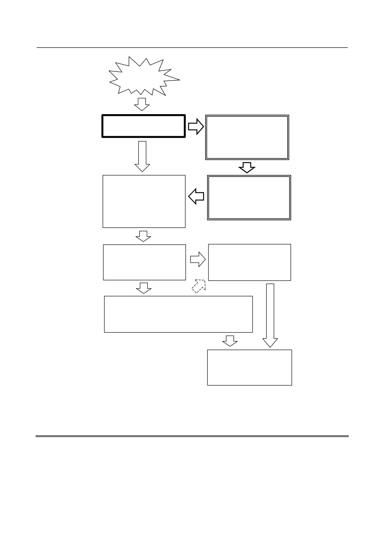
The procedure for taking an action for a problem is shown below.
- 753 -
1.ROUTINE MAINTENANCE
MAINTENANCE
B-64304EN/02
Problem!
Dangerous?
Dangerous
Danger to you and others
Take action to avoid danger.
- Stop machine immediately.
- Refuge to safe place immediately.
Not dangerous
Confirm and secure safety.
Check and identify problem.
- Confirm current safety.
- Warning
- Check machine and circumstances.
- Alarm
- Turn off power to machine.
- Abnormal operation
- Wrong operation, etc.
Check status and how problem
If
recovery
is
impossible,
occurred.
- Time and place of problem
immediately notify sales agent or
occurrence
supplier of problem details for
- Operation procedure
action.
Investigate cause and take action.
- Check and correct machining program and set data items.
- Review and modify operation procedure.
- Check and repair machine operation sections.
Recovery work
- Action by you or machine tool builder
- Check operation after recovery.
For details of investigation and action on problems arising from the CNC, refer to
"TROUBLESHOOTING PROCEDURE" in the Maintenance Manual (B-64305EN) issued by FANUC.
1.2
BACKING UP VARIOUS DATA ITEMS
With the CNC, various data items such as offset data and system parameters are stored in the SRAM of
the control unit and are protected by a backup battery. However, an accident can erase the data. By
storing the data at another location (outside the CNC), the data, when lost, can be restored.
So, when the machine is started up or data is updated, for example, the data should be backed up (stored
outside the CNC).
- 754 -
B-64304EN/02
MAINTENANCE
1.ROUTINE MAINTENANCE
-
Data backup operation
The data items listed below should be backed up. For the method of data output operation, see the
chapter of "DATA INPUT/OUTPUT" in this manual.
<1> Machining programs
→ See III-8.2.1.
<2> System parameters
→ See III-8.2.2.
<3> Tool offset data
→ See III-8.2.3.
<4> PMC data
→ See PMC PROGRAMMING MANUAL (B-64393EN).
<5> Pitch error compensation data (when the pitch error compensation function is selected.)
→ See III-8.2.4.
<6> Custom macro variables (when the custom macro function is selected.)
→ See III-8.2.5.
<7> Workpiece coordinate system setting data (when the workpiece coordinate system function is
selected.)
→ See III-8.2.6.
<8> Operation history data
→ See III-8.2.7.
It is recommended that recording media (such as floppy disks and memory cards) daily used with the
machine be used to store data. Stored data should be managed properly so that the data can be restored
quickly if a problem occurs.
-
Data restoration work
In order to restore lost data to the state of the stored data, input the data backed up according to the
previous item into the CNC. For the method of data input operation, see the chapter of "DATA
INPUT/OUTPUT" in this manual.
WARNING
After inputting stored data, do not start an operation immediately. Instead,
check that the data is input correctly and that settings are made to meet a
desired operation.
If an operation is executed without making this check, the machine and
workpiece can be damaged and personal injury can occur due to an unexpected
machine movement. Use sufficient care.
CAUTION
Before recovery of the following data items, consult with the machine tool builder
of the machine used:
• System parameters
• PMC data
• Macro programs and custom macro variables
• Pitch error compensation values
- 755 -