FANUC Series 0i-MODEL D, Series 0i Mate-MODEL D. OPERATOR'S MANUAL - page 15

4.AUTOMATIC OPERATION
OPERATION
B-64304EN/02
5
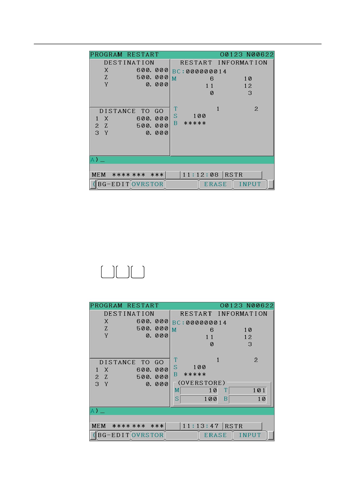
The block number is searched for, and the program restart screen appears on the LCD display.
Fig. 4.9 (b) Program restart screen
DESTINATION shows the position at which machining is to restart.
DISTANCE TO GO shows the distance from the current tool position to the position where
machining is to restart. A number to the left of each axis name indicates the order of axes
(determined by parameter setting) along which the tool moves to the restart position.
The coordinates and amount of travel for restarting the program can be displayed for up to four axes.
For a path with five axes, when soft key [RSTR] is pressed again to display the fifth axis.
M
:
Up to 35 most recently specified M codes. The maximum number of displayed M codes
differs depending on the size of the display.
With 10.4-inch LCD/MDI panel : Up to 30 M codes
With 8.4-inch LCD/MDI panel : Up to 6 M codes
T
:
Two most recently specified T codes
S
:
Most recently specified S code
B
:
Most recently specified B code
Codes are displayed in the order in which they are specified. All codes are cleared by a
program restart command or cycle start in the reset state.
6
Turn the program re-start switch OFF. At this time, the figure at the left side of axis name
DISTANCE TO GO blinks.
7
Check the screen for the M, S, T, and B codes to be executed. If they are found, enter the MDI
mode, then execute the M, S, T, and B functions. After execution, restore the previous mode.
These codes are not displayed on the program restart screen.
8
Check that the distance indicated under DISTANCE TO GO is correct. Also check whether there
is the possibility that the tool might hit a workpiece or other objects when it moves to the machining
restart position. If such a possibility exists, move the tool manually to a position from which the
tool can move to the machining restart position without encountering any obstacles.
9
Press the cycle start button. The tool moves to the machining restart position at the dry run feedrate
sequentially along axes in the order specified by parameter No. 7310 settings. Machining is then
restarted.
- 396 -

B-64304EN/02
OPERATION
4.AUTOMATIC OPERATION
Outputting the M, S, T, and B codes for program restart
After the block to be restarted is searched for, you can perform the following operations:
1
Before the tool is moved to the machining restart position
<1> The most recently specified M, S, T, and B codes can automatically be output to the PMC.
The most recently specified S code is output as the maximum spindle speed when the S code is
specified in the block containing G92 or as the specified spindle speed in other cases. As the
most recently specified S code, only one S code is displayed on the program restart screen
regardless of whether the S code is specified in the block containing G92.
<2> While the block to be restarted is being searched for, all sampled M codes and most recently
specified S, T, and B codes can automatically be output to the PMC. Up to 35 M codes can be
sampled. If the number of sampled M codes exceeds 35, the 35 most recently specified M
codes are output to the PMC.
Switch between operations <1> and <2> using bit 6 (MOA) of parameter No. 7300.
2
Before the tool reaches the machining restart position
On the program restart screen, you can specify M, S, T, and B codes from the MDI panel in the
MEM or RMT mode without changing the mode.
Outputting the most recently specified M, S, T, and B codes
When bit 7 (MOU) of parameter No. 7300 is 1 and bit 6 (MOA) of parameter No. 7300 is 0, if the cycle
start button is pressed after searching for the block to be restarted, the last M, S, T, and B codes are
automatically output to PMC before moving to the machining restart point.
In the single block stop status, after the most recently specified M, S, T, and B codes are output, pressing
the cycle start switch again moves the tool to the machining restart position.
Outputting all M codes and most recently specified S, T, and B codes
When bit 7 (MOU) of parameter No. 7300 is 1 and bit 6 (MOA) of parameter No. 7300 is 1, if the cycle
start button is pressed after searching for the block to be restarted, all M codes and the last S, T, and B
codes are automatically output to PMC before moving to the machining restart point.
(Example)
When M10, M11, M12, M13, M14, T0101, S1000, and B10 are sampled, a program is executed in
the format shown below before the tool is moved to the machining restart position:
M10 T0101 S1000 B10 ;
M11 ;
M12 ;
M13 ;
M14 ;
Outputting M, S, T, and B codes on the program restart screen
When bit 7 (MOU) of parameter No. 7300 is set to 1, you can specify M, S, T, and B codes from the MDI
panel in the MEM or RMT mode without changing the mode after searching for the block to be restarted
until the tool reaches the machining restart position.
Procedure
1
When the block to be restarted is searched for using the program restart function, the program restart
screen appears. When bit 7 (MOP) of parameter No. 7300 is set to 1, operation soft keys
[OVERSTORE], [ERASE], and [INPUT] are displayed.
- 397 -
4.AUTOMATIC OPERATION
OPERATION
B-64304EN/02
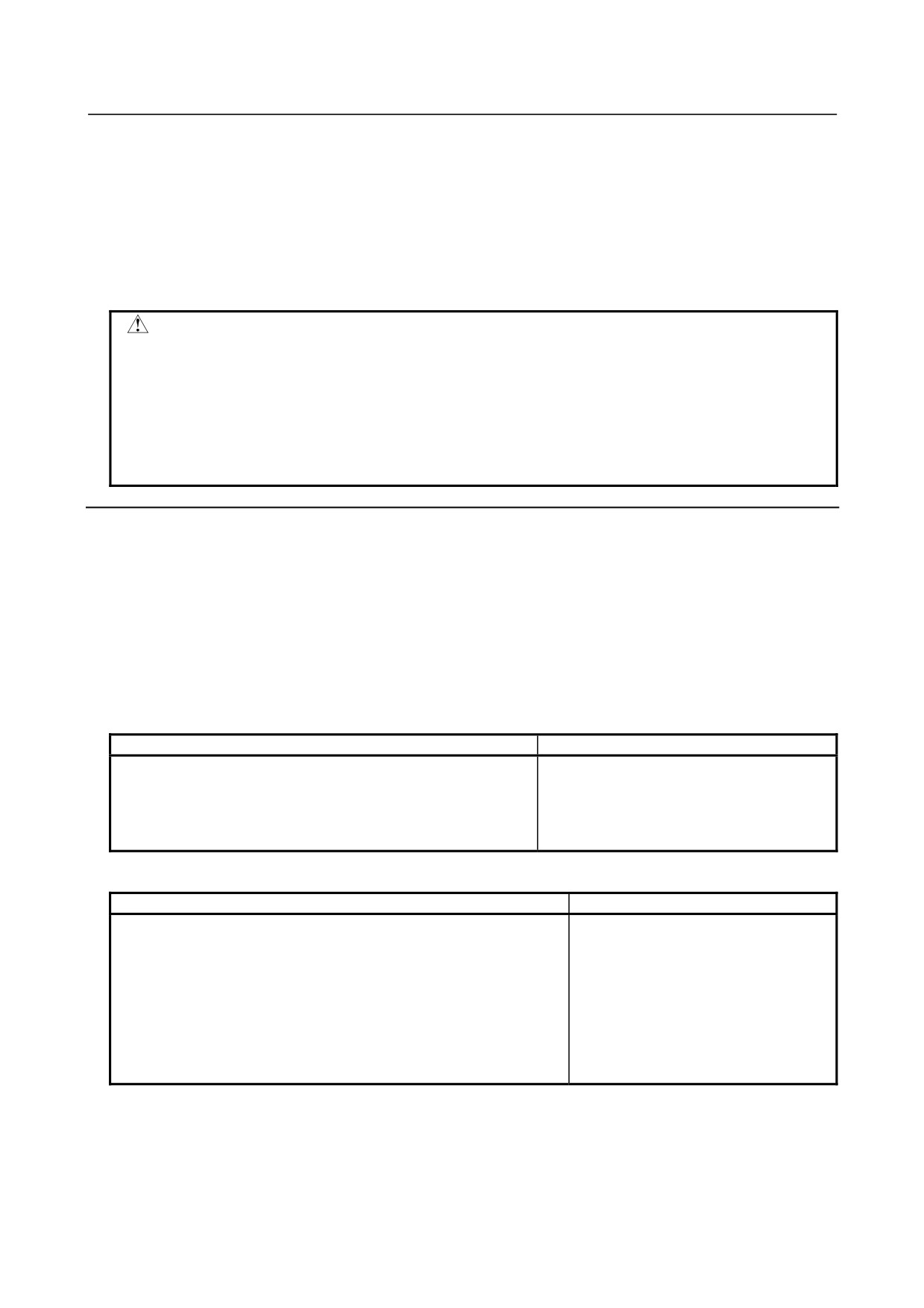
Fig. 4.9 (c) Program restart screen (outputting M, S, T, and B codes)
2
Before the tool reaches the machining restart position, pressing soft key [OVERSTORE] selects the
over store mode. In the over store mode, data can be entered in the M, S, T, and B fields displayed
in the (OVERSTORE) section.
To select the over store mode while the tool is moving to the machining restart position, hold restart
operation by feed hold and press soft key [OVERSTORE].
Enter M, S, T, and B codes to be output in the (OVERSTORE) section from the MDI panel.
(Example)
To enter M10, S1000, T101, and B20 in the (OVERSTORE) section:
<1> Enter
M
1
0
from the MDI panel.
<2> Press the [INPUT] key.
You can also enter the S, T, and B codes by performing steps <1> and <2>.
Fig. 4.9 (d) Program restart screen when M, S, T, and B codes are output
- 398 -
B-64304EN/02
OPERATION
4.AUTOMATIC OPERATION
3
When values have been entered in the (OVERSTORE) section, pressing the cycle start switch
outputs each code in the (OVERSTORE) section. The values in the (OVERSTORE) section are
cleared.
4
To clear the values entered in the (OVERSTORE) section as M, S, T, and B codes, press soft key
[ERASE]. All entered values are cleared.
5
Pressing soft key [OVERSTORE] again in the over store mode cancels the mode. Pressing the
reset key also cancels the over store mode.
6
To continue with restart operation, cancel the over store mode and press the cycle start switch.
CAUTION
1 The M, S, T, and B codes specified in the over store mode are not displayed on
the program restart screen.
2 In the over store mode, changing the operation mode to other than the MEM or
RMT mode does not cancel the over store mode. In this case, no values can
be entered in the (OVERSTORE) section.
3 In T series, do not specify a T code in the over store mode. If a T code is
specified, it is not executed.
Explanation
-
Block number
When the CNC is stopped, the number of executed blocks is displayed on the program screen or program
restart screen. The operator can specify the number of the block from which the program is to be
restarted, by referencing the number displayed on the screen. The displayed number indicates the
number of the block that was executed most recently. For example, to restart the program from the
block at which execution stopped, specify the displayed number, plus one.
The number of blocks is counted from the start of machining, assuming one NC line of a CNC program to
be one block.
(Example 1)
CNC Program
Number of blocks
O0001 ;
1
G90 G92 X0 Y0 Z0 ;
2
G01 X100. F100 ;
3
G01 Z-50. F50 ;
4
M30 ;
5
(Example 2)
CNC Program
Number of blocks
O0001 ;
1
G90 G92 X0 Y0 Z0 ;
2
G90 G00 Z100. ;
3
G81 X100. Y0. Z120. R-80. F50. ;
4
#1=#1+1 ;
4
#2=#2+1 ;
4
#3=#3+1 ;
4
G00 X0 Z0 ;
5
M30 ;
6
Macro statements are not counted as blocks.
-
Storing / clearing the block number
The block number is held in memory while no power is supplied.
The number can be cleared by cycle
start in the reset state.
- 399 -
4.AUTOMATIC OPERATION
OPERATION
B-64304EN/02
-
Block number when a program is halted or stopped
The program screen usually displays the number of the block currently being executed. When the
execution of a block is completed, the CNC is reset, or the program is executed in single-block stop mode,
the program screen displays the number of the program that was executed most recently. When a CNC
program is halted or stopped by feed hold, reset, or single-block stop, the following block numbers are
displayed:
Feed hold
: Block being executed
Reset
: Block executed most recently
Single-block stop
: Block executed most recently
For example, when the CNC is reset during the execution of block 10, the displayed block number
changes from 10 to 9.
-
MDI intervention
When MDI intervention is performed while the program is stopped by single-block stop, the CNC
commands used for intervention are not counted as a block.
-
Block number exceeding eight digits
When the block number displayed on the program screen exceeds eight digits, the block number is reset
to 0 and counting continues.
Limitation
-
P type Restart
In the following conditions, P type restart cannot be performed:
• Automatic operation has not been performed since power-on.
• Automatic operation has not been performed since the coordinate system was changed or shifted
(change of the external workpiece origin offset value).
-
Restart block
The block where the program is to restart is not necessarily be the block at which the program was
interrupted. You can restart the program from any block. For P-type restart, however, the block where
the program is to restart must use the same coordinate system as when program execution was
interrupted.
-
Single block
When the single-block operation is enabled at the time of a movement to the restart point, a single-block
stop occurs each time an axis operation takes place. In this case, no MDI operation is allowed.
-
Manual intervention
During movement to the restart point, manual intervention is allowed for an axis for which a return
operation has not yet been performed. However, manual operations do not cause any movement along
axes for which a return operation has already been completed.
-
MDI
When the search operation has ended, no move command can be specified by MDI before axis
movement.
-
Reset
Do not perform a reset operation during the time from the start of the search operation of the restart
sequence until machining is restarted.
If a reset operation is performed, the restart steps must be performed again from the beginning.
- 400 -
B-64304EN/02
OPERATION
4.AUTOMATIC OPERATION
-
Feed hold
If a feed hold operation is performed during the search, the restart steps must be performed again from the
beginning.
-
Manual absolute
Every manual operation must be performed with the manual absolute mode turned on regardless of
whether the manual operation is performed before or after machining.
-
Reference position return
Unless an absolute position detector (absolute pulse coder) is provided, be sure to perform reference
position return after power-up, then perform restart operation.
-
Program restart switch
When the program restart switch is on, pressing the cycle start switch does not start operation.
-
Blocks specifying a macro statement, macro call, and subprogram call
Blocks specifying a macro statement, macro call, and subprogram call are not searched for even when
they have a sequence number. In such a case, search for a block previously preceding such a block.
-
Interruption type custom macro
During movement to the machining restart point at a dry run feedrate, no interruption type custom macro
can be started. If an interruption type custom macro is started, alarm DS024 is issued.
M
-
Index table indexing
For a machine that uses index table indexing, position the machine at the restart point in advance before
restarting the program.
-
Commands that prevent program restart
Program restart cannot be performed for blocks placed in the following modes:
• Cs contouring control
• Threading (G32,G33)
• Rigid tapping
T
• Polygon turning (G50.2)
• Threading cycle (G92)
• Multiple repetitive threading cycle (G76)
• Polar coordinate interpolation (G12.1)
• Balance cutting (G68)
If any of the following commands is included between the beginning of a program and the block where
the program is to restart, program restart cannot be performed:
• Workpiece coordinate system preset (G92.1,G50.3)
• Commands for enabling and disabling axis synchronous control
T
• Commands for enabling and disabling synchronous/composite control and superimposed control
- 401 -

4.AUTOMATIC OPERATION
OPERATION
B-64304EN/02
-
M, S, and T commands not usable in over store mode
The M, S, and T functions listed below, unlike the other M, S, and T functions, have special meanings
within the CNC. These M, S, and T commands cannot be specified from the over store screen. To
specify these commands, cancel the over store mode, and execute them in MDI operation.
Example:
•
Rigid tapping
T
•
Spindle positioning
WARNING
As a rule, the tool cannot be returned to a correct position under the following
conditions.
Special care must be taken in the following cases since none of them cause an
alarm:
- Manual operation is performed when the manual absolute mode is OFF.
- Manual operation is performed when the machine is locked.
- When the mirror image is used. However, P type return is possible for a
block that switched between ON and OFF most recently or a subsequent
block. In this case, the mirror image signal status present when the program
was interrupted must be maintained.
- When no coordinate system is set up at the beginning of a program in which
main commands are executed in the incremental mode.
- When manual operation is performed in the course of axis movement for
returning operation.
- When the program restart is commanded for a block between the block for
skip cutting and subsequent absolute command block.
- When program restart is specified in the machine lock state, then the
machine lock is canceled.
- When program restart specified for an intermediate block for a multiple
repetitive canned cycle (T series)
- In general, when a coordinate system is set up, changed, or shifted after the
search operation ends, the tool cannot be returned to a correct position.
CAUTION
Keep the following in mind when restarting a program including macro variables.
- Common variable
When the program is restarted, the previous values are inherited as common
variables without being preset automatically. Before restarting the program,
initialize the appropriate variables to the original values used at start of the
previous automatic operation.
- DI/DO
At restart of the program, DI can be read by a system variable, but DO
cannot be output.
- Clock
When the program is being restarted, the clock time can be obtained by a
system variable, but the time cannot be preset.
- Tool offset and workpiece origin offset
When the program is being restarted, the offset can be read by a system
variable, but change of the offset is allowed only for the Q type.
- 402 -
B-64304EN/02
OPERATION
5.TEST OPERATION
5 TEST OPERATION
The following functions are used to check before actual machining whether the machine operates as
specified by the created program.
5.1 MACHINE LOCK AND AUXILIARY FUNCTION LOCK
403
5.2 FEEDRATE OVERRIDE
404
5.3 RAPID TRAVERSE OVERRIDE
405
5.4 DRY RUN
405
5.5 SINGLE BLOCK
406
5.1
MACHINE LOCK AND AUXILIARY FUNCTION LOCK
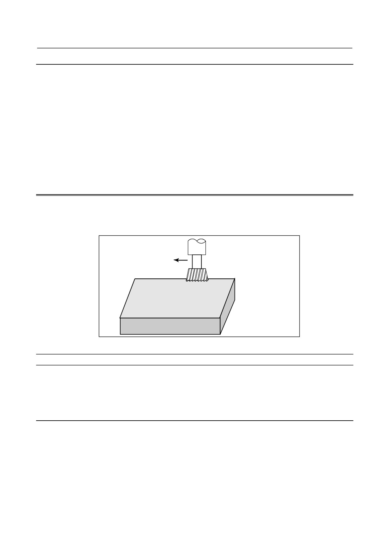
To display the change in the position without moving the tool, use machine lock.
There are two types of machine lock: all-axis machine lock, which stops the movement along all axes,
and specified-axis machine lock, which stops the movement along specified axes only. In addition,
auxiliary function lock, which disables M, S, T, and B (2nd auxiliary function) commands, is available
for checking a program together with machine lock.
Display unit
X
Y
Tool
Z
Workpiece
The tool does not move but the position
along each axis changes on the display.
Fig. 5.1 (a) Machine lock
Machine lock and auxiliary function lock
Procedure
-
Machine Lock
Press the machine lock switch on the operator's panel. The tool does not move but the position along each
axis changes on the display as if the tool were moving.
Some machines have a machine lock switch for each axis. On such machines, press the machine lock
switches for the axes along which the tool is to be stopped. Refer to the appropriate manual provided by
the machine tool builder for machine lock.
WARNING
The positional relationship between the workpiece coordinates and machine
coordinates may differ before and after automatic operation using machine lock.
In such a case, specify the workpiece coordinate system by using a coordinate
setting command or by performing manual reference position return.
-
Auxiliary function lock
Press the auxiliary function lock switch on the operator's panel. M, S, T, and B codes are disabled and not
executed. Refer to the appropriate manual provided by the machine tool builder for auxiliary function
lock.
- 403 -
5.TEST OPERATION
OPERATION
B-64304EN/02
Limitation
-
M, S, T, B command by only machine lock
M, S, T and B commands are executed in the machine lock state.
-
Reference position return under machine lock
When a G27, G28, or G30 command is issued in the machine lock state, the command is accepted but the
tool does not move to the reference position and the reference position return LED does not go on.
-
M codes not locked by auxiliary function lock
M00, M01, M02, M30, M98, M99, and M198 (external subprogram call function) commands are
executed even in the auxiliary function lock state. M codes for calling a subprogram (parameters No.
6071 to 6079) and those for calling a custom macro (parameters No. 6080 to 6089) are also executed.
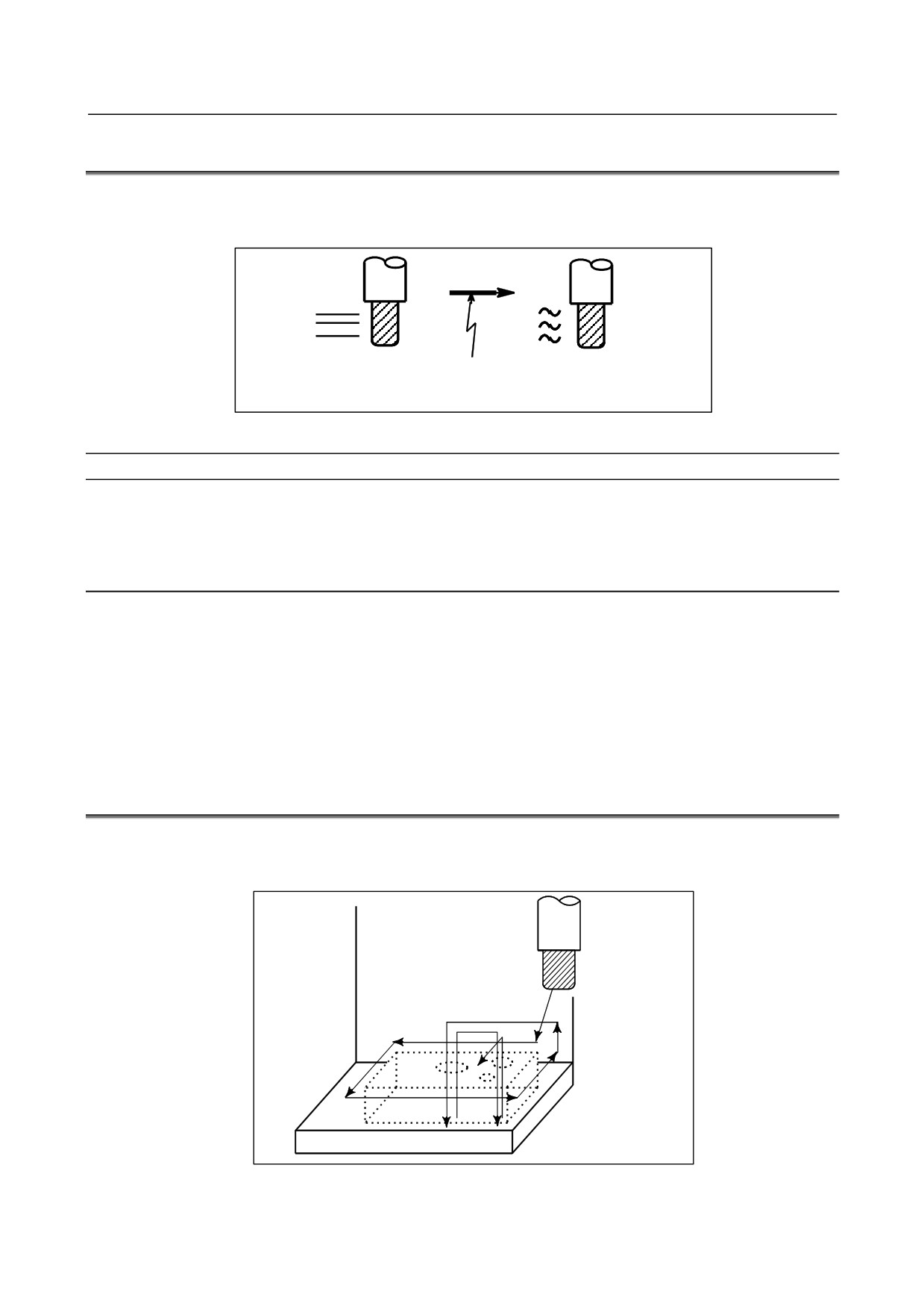
5.2
FEEDRATE OVERRIDE
A programmed feedrate can be reduced or increased by a percentage (%) selected by the override dial.
This feature is used to check a program.
For example, when a feedrate of 100 mm/min is specified in the program, setting the override dial to 50%
moves the tool at 50 mm/min.
Feedrate
100 mm/min
Tool
(Specified by programmed)
Check the machining by
Feedrate
50 mm/min after
altering the feedrate from
feedrate override
the value specified in the
program.
Workpiece
Fig. 5.2 (a) Feedrate override
Feedrate override
Procedure
Set the feedrate override dial to the desired percentage (%) on the machine operator's panel, before or
during automatic operation.
On some machines, the same dial is used for the feedrate override dial and jog feedrate dial. Refer to the
appropriate manual provided by the machine tool builder for feedrate override.
Limitation
-
Override range
The override that can be specified ranges from 0 to 254%. For individual machines, the range depends on
the specifications of the machine tool builder.
-
Override during thread
During the threading process, the override setting is ignored; it is always regarded as 100% during the
process.
- 404 -
B-64304EN/02
OPERATION
5.TEST OPERATION
5.3
RAPID TRAVERSE OVERRIDE
An override of four steps (F0, 25%, 50%, and 100%) can be applied to the rapid traverse rate. F0 is set by
a parameter No. 1421.
A rapid traverse override can be selected in steps of 1% or 0.1% in the range of 0 to 100%.
Rapid traverse rate
Override
5m/min
10m/min
50%
Fig. 5.3 (a) Rapid traverse override
Rapid traverse override
Procedure
Select one of the four feedrates with the rapid traverse override switch during rapid traverse.
Select a rapid traverse override in steps of 1% or 0.1%.
Refer to the appropriate manual provided by the machine tool builder for rapid traverse override.
Explanation
The following types of rapid traverse are available. Rapid traverse override can be applied for each of
them.
(1) Rapid traverse by G00
(2) Rapid traverse during a canned cycle
(3) Rapid traverse in G27, G28, G29 (M series), G30, G53
(4) Manual rapid traverse
(5) Rapid traverse of manual reference position return
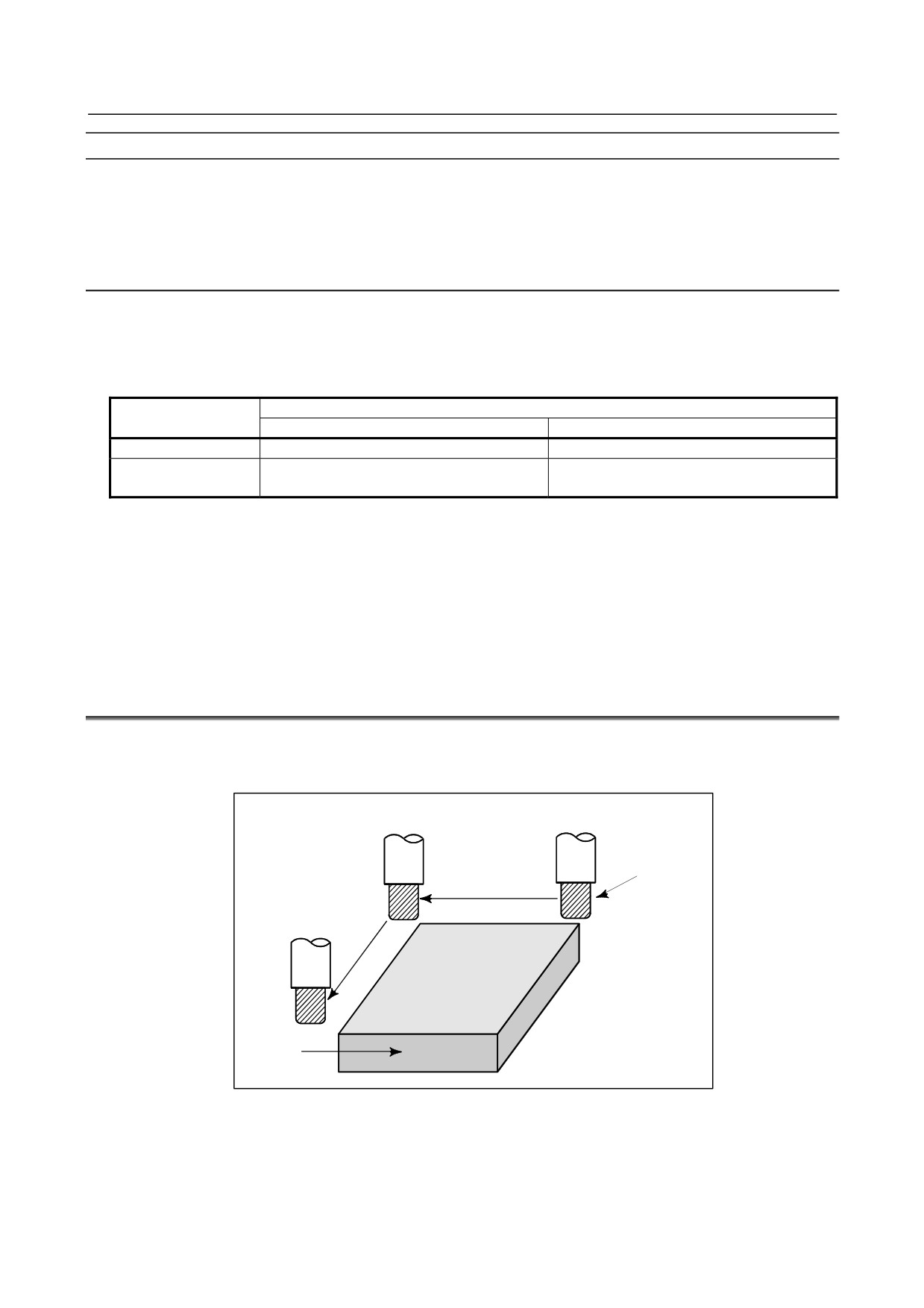
5.4
DRY RUN
The tool is moved at the feedrate specified by a parameter regardless of the feedrate specified in the
program. This function is used for checking the movement of the tool under the state that the workpiece is
removed from the table.
Tool
Table
Fig. 5.4 (a) Dry run
- 405 -
5.TEST OPERATION
OPERATION
B-64304EN/02
Dry run
Procedure
Press the dry run switch on the machine operator's panel during automatic operation.
The tool moves at the feedrate specified in a parameter. The rapid traverse switch (manual rapid traverse
selection signal) can also be used for changing the feedrate. Refer to the appropriate manual provided by
the machine tool builder for dry run.
Explanation
-
Dry run feedrate
The dry run feedrate changes as shown in the table below according to the rapid traverse switch (manual
rapid traverse selection signal) and parameters.
Table 5.4 (a) Feedrate during dry run
Program command
Rapid traverse switch
Rapid traverse
Cutting feed
ON
Rapid traverse rate
Dry run feedrate × Jvmax(*2)
Dry run feedrate × JV,
OFF
Dry run feedrate × JV(*2)
or rapid traverse rate (*1)
Max. cutting feedrate
Setting by parameter No.1430
Rapid traverse rate
Setting by parameter No.1420
Dry run feedrate
Setting by parameter No.1410
(*1) Dry run feedrate × JV when parameter RDR (No. 1401#6) is 1. Rapid traverse rate when parameter
RDR is 0.
JV Jog feedrate override
(*2) Clamped to the maximum cutting feedrate
Jvmax Maximum value of jog feedrate override
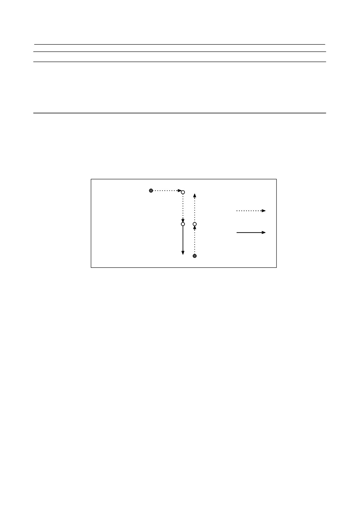
5.5
SINGLE BLOCK
Pressing the single block switch starts the single block mode. When the cycle start button is pressed in the
single block mode, the tool stops after a single block in the program is executed. Check the program in
the single block mode by executing the program block by block.
Cycle start
Cycle start
Tool
Cycle start
Stop
Stop
Workpiece
Stop
Fig. 5.5 (a) Single block
- 406 -
B-64304EN/02
OPERATION
5.TEST OPERATION
Single block
Procedure
1
Press the single block switch on the machine operator's panel.
The execution of the program is stopped after the current block is executed.
2
Press the cycle start button to execute the next block. The tool stops after the block is executed.
Refer to the appropriate manual provided by the machine tool builder for single block execution.
Explanation
-
Reference position return and single block
If G28, G29 (M series), and G30 are issued, the single block function is effective at the intermediate
point.
-
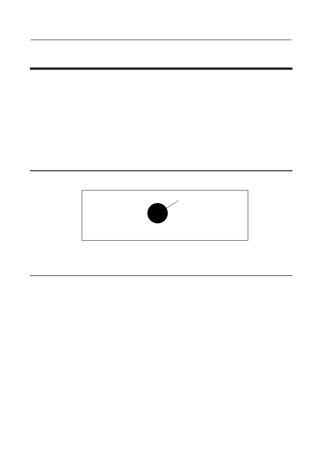
Single block during a canned cycle
In a canned cycle, the single block stop points are the end of <1>, <2>, and <6> shown below. When the
single block stop is made after the point <1> or <2>, the feed hold LED lights.
<1>
<2>
<6>
Rapid
traverse
<3>
Cutting feed
<5>
<4>
Fig. 5.5 (b) Single block during canned cycle
-
Subprogram call and single block
Single block stop is not performed in a block containing M98P_ ;. M99 ; or G65.
However, single block stop is even performed in a block with M98P_ or M99 command, if the block
contains an address other than O, N, P, L.
- 407 -
6.SAFETY FUNCTIONS
OPERATION
B-64304EN/02
6 SAFETY FUNCTIONS
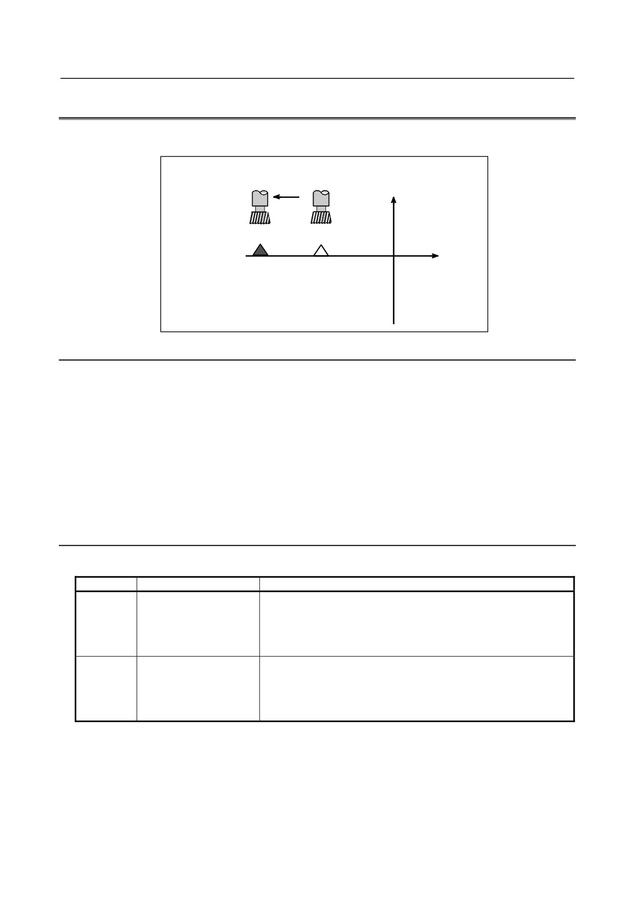
To immediately stop the machine for safety, press the Emergency stop button. To prevent the tool from
exceeding the stroke ends, Overtravel check and Stored stroke check are available. This chapter describes
emergency stop, overtravel check, and stored stroke check.
Chapter 6, "SAFETY FUNCTIONS", consists of the following sections:
6.1 EMERGENCY STOP
408
6.2 OVERTRAVEL
409
6.3 STORED STROKE CHECK
410
6.4 STROKE LIMIT CHECK BEFORE MOVE
414
6.5 WRONG OPERATION PREVENTION FUNCTIONS
416
6.1
EMERGENCY STOP
If you press Emergency Stop button on the machine operator's panel, the machine movement stops in a
moment.
Red
EMERGENCY STOP
Fig. 6.1 (a) Emergency stop
This button is locked when it is pressed. Although it varies with the machine tool builder, the button can
usually be unlocked by twisting it.
Explanation
EMERGENCY STOP interrupts the current to the motor.
Causes of trouble must be removed before the button is released.
- 408 -
B-64304EN/02
OPERATION
6.SAFETY FUNCTIONS
6.2
OVERTRAVEL
When the tool tries to move beyond the stroke end set by the machine tool limit switch, the tool
decelerates and stops because of working the limit switch and an OVER TRAVEL is displayed.
Deceleration
and stop
Y
X
Stroke end
Limit
switch
Fig. 6.2 (a) Overtravel
Explanation
-
Overtravel during automatic operation
When the tool touches a limit switch along an axis during automatic operation, the tool is decelerated and
stopped along all axes and an overtravel alarm is displayed.
-
Overtravel during manual operation
In manual operation, the tool is decelerated and stopped only along the axis for which the tool has
touched a limit switch. The tool still moves along the other axes.
-
Releasing overtravel
Press the reset button to reset the alarm after moving the tool to the safety direction by manual operation.
For details on operation, refer to the operator's manual of the machine tool builder.
Alarm
Table6.2 (a)
Alarm No.
Message
Description
The stroke limit switch in the positive direction was triggered.
This alarm is generated when the machine reaches the stroke end.
OT0506
+ OVERTRAVEL ( HARD )
When this alarm is not generated, feed of all axes is stopped during
automatic operation. During manual operation, only the feed of the axis
on which the alarm occurred is stopped.
The stroke limit switch in the negative direction was triggered.
This alarm is generated when the machine reaches the stroke end.
OT0507
- OVERTRAVEL ( HARD )
When this alarm is not generated, feed of all axes is stopped during
automatic operation. During manual operation, only the feed of the axis
on which the alarm occurred is stopped.
- 409 -
6.SAFETY FUNCTIONS
OPERATION
B-64304EN/02
6.3
STORED STROKE CHECK
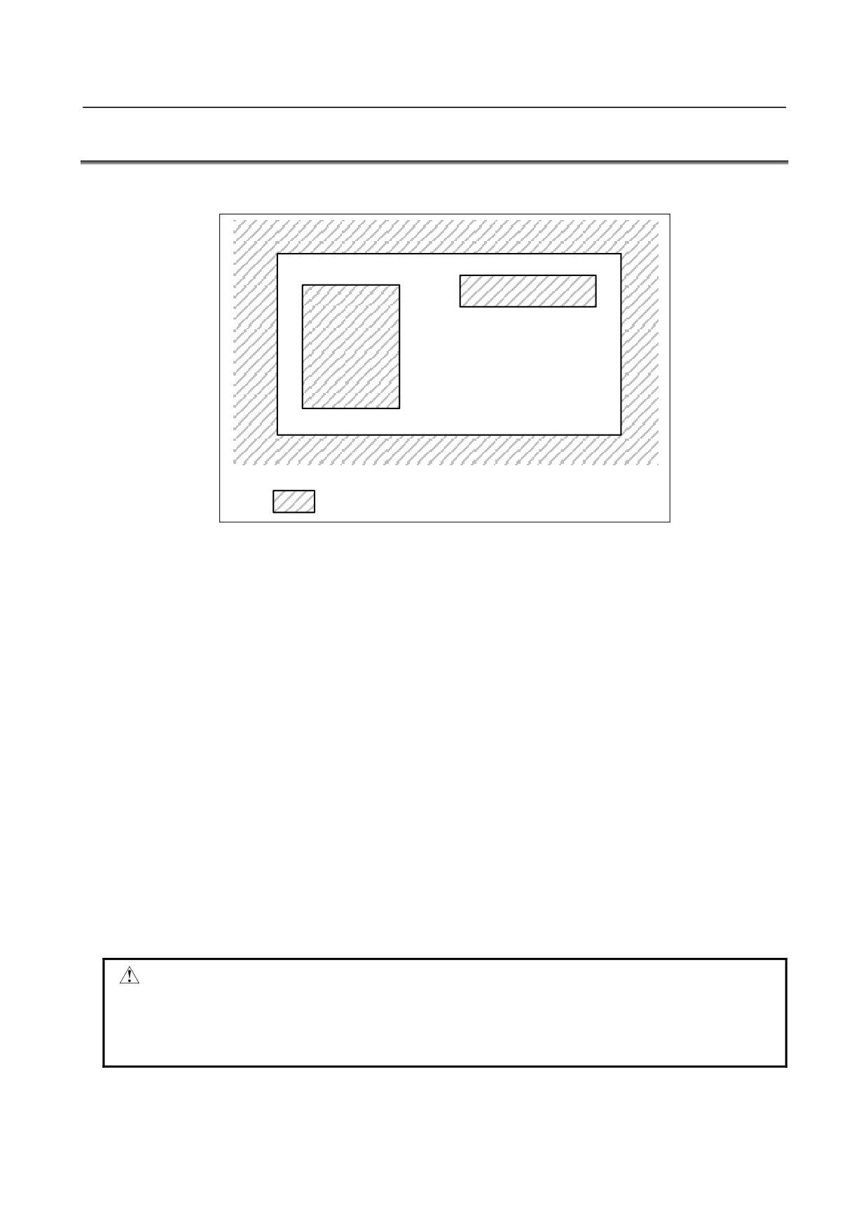
Three areas which the tool cannot enter can be specified with stored stroke check 1, stored stroke check 2,
and stored stroke check 3.
Stored stroke check 3
Stored
stroke
check 2
Stored stroke check 1
: Forbidden area for the tool
Fig. 6.3 (a) Stroke check
The following shows the areas which the tool cannot enter for each stored stroke check.
• Stored stroke check 1: Outside
• Stored stroke check 2: Outside or inside (switchable)
• Stored stroke check 3: Inside
When the tool moves into the forbidden area, an alarm is displayed and the tool is decelerated and
stopped.
When the tool enters a forbidden area and an alarm is generated, the tool can be moved in the reverse
direction from which the tool came.
Explanation
-
Stored stroke check 1
Parameters (Nos. 1320, 1321 or Nos. 1326, 1327) set boundary. Outside the area of the set limits is a
forbidden area. The machine tool builder usually sets this area as the maximum stroke.
When the tool enters a forbidden area and an alarm is generated, the tool can be moved in the reverse
direction from which the tool came.
At this time, a signal (overtravel alarm signal) can be output to the PMC if bit 6 (OTS) of parameter No.
1301 is set to 1. In addition, when the tool enters the forbidden area during manual operation, the signal
(overtravel alarm signal) can be output to the PMC without generating the alarm by setting bit 1 (NAL) of
parameter No. 1300 to 1. With this parameter setting, the alarm is generated when the tool enters the
forbidden area during automatic operation.
CAUTION
1 If the two points for specifying a forbidden area are identical, all areas are
handled as forbidden areas for stored stroke check 1.
2 The size of a forbidden area must be set carefully. If the size is set incorrectly,
the stroke becomes infinite.
- 410 -
B-64304EN/02
OPERATION
6.SAFETY FUNCTIONS
-
Stored stroke check 2
Parameters (Nos. 1322, 1323) or commands set these boundaries. Inside or outside the area of the limit
can be set as the forbidden area. Parameter OUT (No. 1300#0) selects either inside or outside as the
forbidden area.
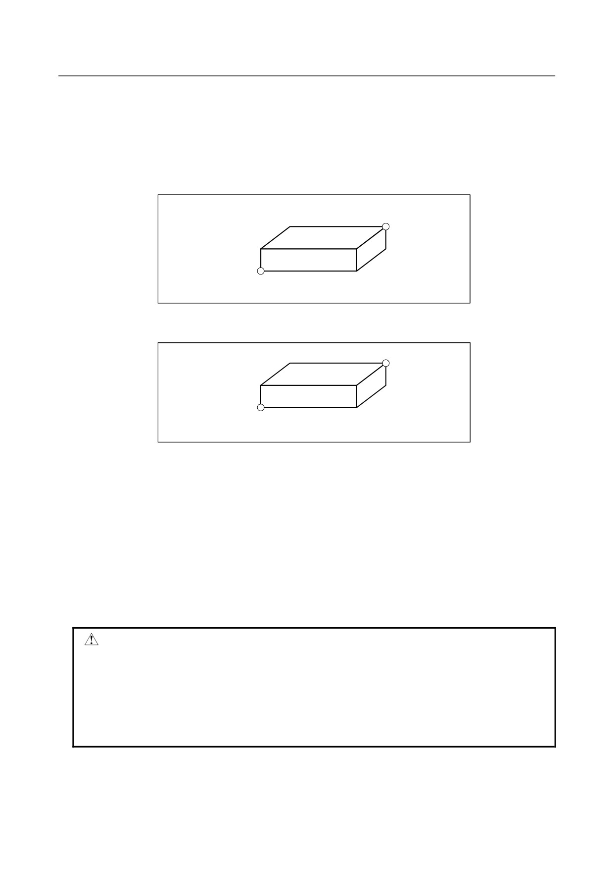
In case of program command a G22 command forbids the tool to enter the forbidden area, and a G23
command permits the tool to enter the forbidden area.
Each of G22; and G23; should be commanded independently of another commands in a block.
The command below creates or changes the forbidden area:
G22 X_ Y_ Z_ I_ J_ K_ ;
(X, Y, Z)
(I, J, K)
X>I, Y>J, Z>K
Fig. 6.3 (b) Creating or changing the forbidden area using a program
When setting the area by parameters, points A and B in the figure below must be set.
A(X1, Y1, Z1)
B(X2, Y2, Z2)
X1>X2, Y1>Y2, Z1>Z2
Fig. 6.3 (c) Creating or changing the forbidden area using a parameters
The values X1, Y1, Z1, X2, Y2, and Z2, which are set by parameters No. 1322 and No. 1323, must be
specified by the distance from the machine coordinate system (machine unit). The values X, Y, Z, I, J,
and K, which are set by a G22 command, must be specified by the distance in the least input increment
(input unit).
Values set by a program are then converted in the machine increment and the values are set as the
parameters.
-
Stored stroke check 3
Set the boundary with parameters No. 1324 and 1325. The area inside the boundary becomes the
forbidden area. The values X1, Y1, Z1, X2, Y2, and Z2 must be set as coordinates (machine unit) in the
machine coordinate system.
CAUTION
1 If the two points for specifying a forbidden area are identical, all areas are
handled as movable areas for stored stroke check 2/3.
2 Even if the magnitude relation of the two points for specifying a forbidden area is
incorrectly set, a rectangular parallelepiped having the two points as apexes on
its diagonal line is assumed as the boundaries in stored stroke check 2/3.
3 Since an axis without the reference position return function has no forbidden
areas, there are no alarms about forbidden areas for the axis.
-
Checkpoints in the forbidden area
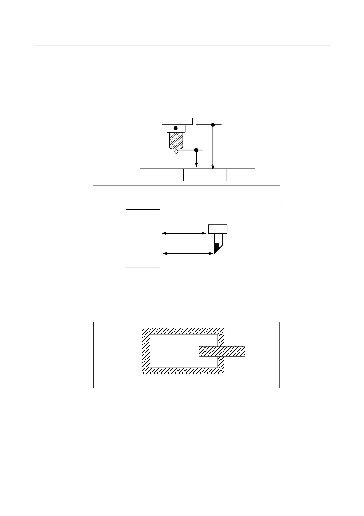
The parameter setting or programmed value (XYZIJK) depends on which part of the tool or tool holder is
checked for entering the forbidden area.
- 411 -
6.SAFETY FUNCTIONS
OPERATION
B-64304EN/02
If point A (the top of the tool) is checked in Fig. 6.3(d), the distance "a" should be set as the data for the
stored stroke limit function. If point B (the tool chuck) is checked, the distance "b" must be set. A 点
When a tool tip such as point A is checked, if the length and diameter of the tool change variously, make
settings using the maximum length and diameter. This eliminates the setting for each tool and makes
machining safe.
• For machining center system
B
The position of the
tool after reference
position return
b
Area boundary
A
a
• For lathe system
b
B
a
A
The position of the
tool after reference
Forbitten area boundary
position return
Fig. 6.3 (d) Setting the forbidden area
-
Forbidden area overlapping
Area can be set in piles.
Setting the forbidden area overlapping
Fig. 6.3 (e) Setting the forbidden area overlapping
Unnecessary limits should be set beyond the machine stroke.
-
Condition under which each check is enabled
Each check becomes effective after the power is turned on and manual reference position return or
automatic reference position return by G28 has been performed.
After the power is turned on, if the reference position is in the forbidden area of each limit, an alarm is
generated immediately.
(Only in G22 mode for stored stroke check 2).
- 412 -
B-64304EN/02
OPERATION
6.SAFETY FUNCTIONS
-
Releasing the alarms
If the enters a forbidden area and an alarm is generated, the tool can be moved only in the backward
direction. To cancel the alarm, move the tool backward until it is outside the forbidden area and reset
the system. When the alarm is canceled, the tool can be moved both backward and forward.
When bit 4 (OF1) of parameter No.1301 is 1, if the axis moves within the movable area after an alarm
occurs in stored stroke check 1, the OT alarm is cleared without a reset (automatic clearance function).
NOTE
In the following cases, the automatic clearance function is disabled. To clear an
alarm, make a reset.
1 An alarm is set to occur before the stored stroke limit is exceeded (bit 7 (BFA)
of parameter No. 1300 is 1).
2 Another over travel alarm (such as stored stroke check 2/3 and interference
check) occurs.
-
Change from G23 to G22 in a forbidden area
When G23 is switched to G22 in the forbidden area, the following results.
<1> When the forbidden area is inside, an alarm is informed in the next move.
<2> When the forbidden area is outside, an alarm is informed immediately.
-
Timing for displaying an alarm
In stored stroke check 1/2/3, parameter BFA (bit 7 of No. 1300) selects whether an alarm is displayed
immediately before the tool enters the forbidden area or immediately after the tool has entered the
forbidden area.
Alarm
Number
Message
Description
A movement in the positive direction exceeded stored
OT0500
+ OVERTRAVEL (SOFT 1)
stroke check 1.
A movement in the negative direction exceeded stored
OT0501
- OVERTRAVEL (SOFT 1)
stroke check 1.
A movement in the positive direction exceeded stored
OT0502
+ OVERTRAVEL (SOFT 2)
stroke check 2.
A movement in the negative direction exceeded stored
OT0503
- OVERTRAVEL (SOFT 2)
stroke check 2.
A movement in the positive direction exceeded stored
OT0504
+ OVERTRAVEL (SOFT 3)
stroke check 3.
A movement in the negative direction exceeded stored
OT0505
- OVERTRAVEL (SOFT 3)
stroke check 3.
- 413 -
6.SAFETY FUNCTIONS
OPERATION
B-64304EN/02
6.4
STROKE LIMIT CHECK BEFORE MOVE
During automatic operation, before the movement specified by a given block is started, whether the tool
enters the forbidden area defined by stored stroke check 1, 2, or 3 is checked by determining the position
of the end point from the current position of the machine and a specified amount of travel. If the tool is
found to enter the forbidden area defined by a stored stroke limit, the tool is stopped immediately upon
the start of movement for that block, and an alarm is displayed.
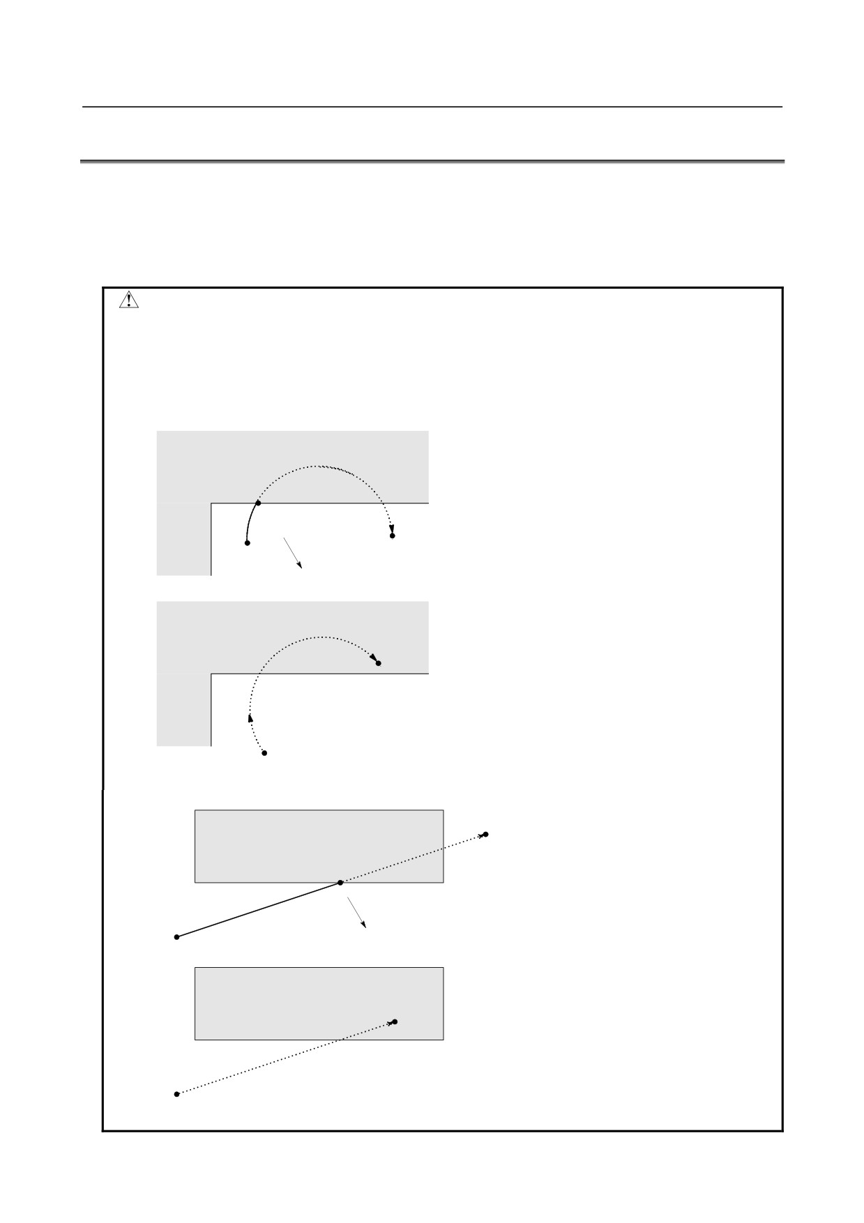
WARNING
Whether the coordinates of the end point, reached as a result of traversing the
distance specified in each block, are in a forbidden area is checked. In this case,
the path followed by a move command is not checked. However, if the tool
enters the forbidden area defined by stored stroke check 1, 2, or 3, an alarm is
issued. (See the examples below.)
Example 1)
Forbidden area defined by stored stroke
check 1 or 2
a
End point
Start point
The tool is stopped at point a according to stored stroke check 1 or 2.
Forbidden area defined by stored stroke
check 1 or 2
End point
Immediately upon movement commencing from the start point, the tool is stopped to enable a
stroke limit check before moving to be performed before movement.
Example 2)
Forbidden area defined by stored stroke
End point
check 2 or 3
a
The tool is stopped at point a according to stored stroke check 2 or 3.
Start point
Forbidden area defined by stored stroke
check 2 or 3
End
point
Immediately upon movement commencing from the start point, the tool is stopped to
enable a stroke limit check before moving to be performed before movement.
- 414 -

B-64304EN/02
OPERATION
6.SAFETY FUNCTIONS
Explanation
When a stroke limit check before moving is performed, whether to check the movement performed by a
G31 (skip) block and G37 (automatic tool length measurement (M series) or automatic tool compensation
(T series)) block can be determined using
(parameter NPC (No. 1301#2)).
Limitation
-
Machine lock
If machine lock is applied at the start of movement, no stroke limit check made before movement is
performed.
-
G23
When stored stroke check 2 is disabled (G23 mode), no check is made to determine whether the tool
enters the forbidden area defined by stored stroke check 2.
-
Program restart
When a program is restarted, an alarm is issued if the restart position is within a forbidden area.
-
Manual intervention following a feed hold stop
When the execution of a block is restarted after manual intervention following a feed hold stop, no alarm
is issued even if the end point following a manual intervention is within a forbidden area.
-
A block consisting of multiple operations
If a block consisting of multiple operations (such as a canned cycle and automatic reference position
return) is executed, an alarm is issued at the start point of any operation whose end point falls within a
inhibited area.
-
Cylindrical interpolation mode
In cylindrical interpolation mode, no check is made.
T
-
Polar coordinate interpolation mode
In polar coordinate interpolation mode, no check is made.
-
PMC axis control
No check is made for a movement based on PMC axis control.
Alarm
Table 6.4 (a) Alarm
Number
Message
Description
The block end point was found in the + side stroke limit prohibition
+ OVERTRAVEL
OT0510
area during a stroke check before movement.
( PRE-CHECK )
Modify the program.
The block end point was found in the - side stroke limit prohibition
- OVERTRAVEL
OT0511
area during a stroke check before movement.
( PRE-CHECK )
Modify the program.
- 415 -
6.SAFETY FUNCTIONS
OPERATION
B-64304EN/02
6.5
WRONG OPERATION PREVENTION FUNCTIONS
An improper tool offset setting or an improper operation of the machine can result in the workpiece being
cut inadequately or the tool being damaged. Also, if data is lost due to an operation mistake, it takes
extra time to recover from the mistake.
The operation confirmation functions described below are meant to prevent the operator from performing
any unintended operation (hereinafter referred to as an improper operation).
1
Functions that are used when data is set
•
Data check to verify that the offset data is within the valid setting range
•
Incremental input operation confirmation
•
Prohibition of the absolute input by the soft key to prevent any improper absolute or
incremental input operation
•
Confirmation of any operation of deleting the program or all data
•
Confirmation of a data update during the data setting process
2
Functions that are used when the program is executed
•
Highlighting of updated modal information
•
Display of the executed block status prior to the program execution
•
Display of the axis status, such as the mirror image function enabled or the interlock function
enabled
•
Check for starting from the middle of the program
•
Data check to verify that the offset data is within the effective setting range
•
Maximum incremental value check
6.5.1
Functions that are Used When Data is Set
The following functions are provided to prevent improper operations when data is set.
• Input data range check
• Confirmation of incremental input
• Prohibition of the absolute input by the soft key
• Confirmation of the deletion of the program
• Confirmation of the deletion of all data
• Confirmation of a data update during the data setting process
Set these functions on the operation confirmation function setting screen. For the input data range check,
set a valid input data range, e.g. the upper and lower limits, for each input screen. For the other
functions, specify whether to enable or disable them.
For information about how to display the individual setting screens, how to manipulate them, and other
details, see the item “Operation confirmation setting screen” that describes the operation procedures.
6.5.1.1 Input data range check
This function allows an effective data range to be set and checks whether the input data is within the set
range.
Input data range check
Explanation
-
Outline of the input data range check
This function allows an effective data range to be set for the data of each input screen listed later and
checks whether the input data is within the set range. If the input data is out of the effective data range,
the warning message "DATA IS OUT OF RANGE" is displayed and the data is rejected.
- 416 -
B-64304EN/02
OPERATION
6.SAFETY FUNCTIONS
For example, assume that the effective data range for a certain tool offset number is set to -200. to 200,
and that you are going to input 100.[INPUT]. Even if you inadvertently press the 0 key one more time,
resulting in 1000.[INPUT], the input of 1000. is not accepted.
The function detects a setting mistake and prevents the program from running with invalid data.
-
Input screens for which this function is effective
• Tool compensation
• Workpiece origin offset
T
• Y-axis tool offset
• Workpiece shift
-
Settings
To enable this function, set an effective data range for each input screen on the operation confirmation
function setting screen. For information about how to display the individual setting screens, how to set
data ranges, and other details, see the items that describe the setting of the data ranges.
If the set data range is invalid, no data input is accepted. Correct the data range setting, and then input
data.
-
Disabling the function
The input data range check is disabled if you make any of the following settings on the operation
confirmation function setting screen.
• Both the upper and lower limit values for the tool offset number or workpiece coordinate system are
0.
• The upper and lower limit values for each offset are identical.
-
Messages displayed during the input data range check
When the cursor moves into an input field of an input screen, one of the following messages and warning
messages is displayed. No message is displayed when the input data range check is disabled.
When the set effective data range is valid
Message list 1
Input data status
Message
Color
The data in the input field is within the range.
Input range xxx - xxx
Black
The data in the input field is out of the range.
Input range xxx - xxx
Red
xxx: Upper and lower limit values
When the set effective data range is invalid
Message list 2
Range check status
Message
Color
Tool offset number overlap
NG SETTING (OFFSET NUM OVERLAP)
Red
Workpiece coordinate system overlap
NG SETTING (WORK COORD VAL OVERLAP)
Red
Invalid upper and lower limit values
NG SETTING (U-LMT AND L-LMT ILLEGAL)
Red
The message "NG SETTING (U-LMT AND L-LMT ILLEGAL)" is displayed in the following cases:
• The upper and lower limit values are reversed.
• The values are not effective (e.g., more pairs of offset numbers than allowed are set).
• Either of the tool offset numbers is 0.
-
Range check for data changed by G10 or system variable
If the data changed by G10 or system variable is out of the effective data range, the alarm PS0334
"OFFSET DATA OUT OF RANGE" is displayed.
- 417 -

6.SAFETY FUNCTIONS
OPERATION
B-64304EN/02
6.5.1.2 Confirmation of incremental input
This function displays a confirmation message when you attempt to input an incremental value by using
the [+INPUT] soft key.
Confirmation of incremental input
Explanation
-
Outline of the confirmation of incremental input
This function displays a confirmation message when you attempt to input an incremental value by using
the [+INPUT] soft key in any of the input screens listed below. It lets you confirm whether you really
want to change data or not before making that change.
For example, when you set 5.[+INPUT] for 10., the message "15. INPUT OK?" is displayed.
The function prevents improper absolute or incremental input operations.
NOTE
This function cannot be used to input two or more values consecutively by
delimiting them by semicolons (;).
-
Input screens for which this function is effective
• Tool compensation
• Workpiece origin offset
• Settings
• Parameter
• Pitch error compensation
T
• Workpiece shift
• Y-axis tool offset
• Chuck tail stock barrier
-
Settings
In the operation confirmation function setting screen, check or uncheck the "INCREMENTAL INPUT"
box to enable or disable this function. For information about how to display the setting screen, how to
set the function, and other details, see the item “Operation confirmation setting” that describes the setting
of the operation confirmation function.
6.5.1.3 Prohibition of the absolute input by the soft key
This function prohibits the absolute input using the [INPUT] soft key.
Prohibition of the absolute input by the soft key
Explanation
-
Outline of the prohibition of the absolute input by the soft key
This function prohibits the absolute input by the [INPUT] soft key in the input screens listed later.
It prevents improper absolute or incremental input operations by requiring that the absolute input be made
using the
MDI key and that the incremental input be made using the [+INPUT] soft key.
- 418 -

B-64304EN/02
OPERATION
6.SAFETY FUNCTIONS
-
Input screens for which this function is effective
• Tool compensation
• Workpiece origin offset
T
• Y-axis tool offset
• Workpiece shift
-
Settings
In the operation confirmation function setting screen, check or uncheck the "DISABLED
SOFTKEY[INPUT] IN" box to enable or disable this function. For information about how to display
the setting screen, how to set the function, and other details, see the item “Operation confirmation setting”
that describes the setting of the operation confirmation function.
6.5.1.4 Confirmation of the deletion of the program
This function displays the confirmation message "DELETE PROGRAM ?" when you attempt to delete
the program.
Confirmation of the deletion of the program
Explanation
-
Outline of the confirmation of the deletion of the program
When you attempt to delete the program, this function displays the confirmation message "DELETE
PROGRAM (program name)?" It lets you confirm whether you really want to delete the program or not
before executing the deletion.
The function prevents the program from being deleted due to an improper operation.
-
Settings
In the operation confirmation function setting screen, check or uncheck the "PROGRAM DELETE" box
to enable or disable this function. For information about how to display the setting screen, how to set
the function, and other details, see the item “Operation confirmation setting” that describes the setting of
the operation confirmation function.
6.5.1.5 Confirmation of the deletion of all data
This function displays the confirmation message "DELETE ALL DATA?" when you attempt to delete all
data.
Confirmation of the deletion of all data
Explanation
-
Outline of the confirmation of the deletion of all data
When you attempt to delete all data on the input screen described later, this function displays the
confirmation message "DELETE ALL DATA?". It lets you confirm whether you really want to delete
all data or not before executing the deletion.
The function prevents all data from being deleted due to an improper operation.
-
Input screens for which this function is effective
• Tool compensation
- 419 -
6.SAFETY FUNCTIONS
OPERATION
B-64304EN/02
T
• Y-axis tool offset
-
Settings
In the operation confirmation function setting screen, check or uncheck the "ALL DATA DELETE" box
to enable or disable this function. For information about how to display the setting screen, how to set
the function, and other details, see the item “Operation confirmation setting” that describes the setting of
the operation confirmation function.
6.5.1.6 Confirmation of a data update during the data setting process
This function displays the [CAN] and [EXEC] soft keys for confirmation when you attempt to update the
data of an input screen during the data setting process.
Confirmation of a data update during the data setting process
Explanation
-
Outline of the confirmation of a data update during the data setting process
When you input data in input screen during the data setting process, this function displays the [CAN] and
[EXEC] soft keys for confirmation. It lets you confirm whether you really want to update the data or not
before executing the update.
The function prevents set values from being lost due to an improper operation.
If you input data using the [+INPUT] soft key when the confirmation of incremental input is enabled, a
message is displayed to confirm the incremental input.
-
Settings
In the operation confirmation function setting screen, check or uncheck the "INPUT IN SETTING" box
to enable or disable this function. For information about how to display the setting screen, how to set
the function, and other details, see the item “Operation confirmation setting” that describes the setting of
the operation confirmation function.
6.5.2
Functions that are Used when the Program is Executed
Overview
The following functions are provided to prevent improper operations when the program is executed.
• Display of updated modal information
• Start check signal
• Axis status display
• Confirmation of the start from a middle block
• Data range check
• Maximum incremental value check
• Warning indication during a reset in program operation
Enable or disable each of the functions on the wrong operation prevention function setting screen.
To enable or disable "Warning indication during a reset in program operation", set bit 0 (MDW) of
parameter No. 10334 instead of the wrong operation prevention function setting screen.
For information about how to display the setting screen, how to manipulate it, and other details, see the
item “Operation confirmation setting screen” that describes the operation procedures.
- 420 -

B-64304EN/02
OPERATION
6.SAFETY FUNCTIONS
6.5.2.1 Display of updated modal information
This function allows modal information updated by the NC command or RESET to be highlighted in the
modal information display for the current block.
Display of updated modal information
Explanation
-
Outline of the display of updated modal information
This function allows modal information updated by the NC command or RESET to be highlighted in the
modal information display for the current block.
For example, when a absolute command has been changed to an incremental command or when the
workpiece coordinate system has been initialized by RESET, the function displays the changed part of the
data in an easy-to-recognize manner, in order to prevent improper operations during the execution of the
program.
-
Settings
In the operation confirmation function setting screen, check or uncheck the "UPDATE MODAL
HIGHLIGHT DISPLAY" box to enable or disable this function. For information about how to display
the setting screen, how to set the function, and other details, see the item “Operation confirmation setting”
that describes the setting of the operation confirmation function.
6.5.2.2 Start check signal
This function displays the remaining amount of travel and modal information of the block to be executed
and puts the program to a temporary halt before the program is executed.
Start check signal
Explanation
-
Outline of the start check signal
When a cycle start is made with the start check signal STCHK <G0408.0> set to 1, the function displays
the remaining amount of travel and modal information of the block to be executed and puts the program
to a temporary halt. Making the cycle start again resumes the execution of the program.
The function lets you check the status of the block before executing it, thus helping to prevent improper
operations at the time of execution.
Using this function in combination with the updated modal information display function described in the
preceding subsection makes it easier to check the status of the block to be executed.
-
Settings
This function does not require any setting on the operation confirmation function setting screen.
6.5.2.3 Axis status display
This function displays the axis status to the left of the axis name in the coordinate display screen.
Axis status display
Explanation
-
Outline of the axis status display
This function displays the axis status to the left of the axis name in the display of the machine coordinates,
absolute coordinates, relative coordinates, and remaining travel amounts.
For example, when the mirror image function is enabled for the X1 axis, the absolute coordinates are
displayed as follows.
- 421 -

6.SAFETY FUNCTIONS
OPERATION
B-64304EN/02
ABSOLUTE
M X1
10.000
Y1
10.000
Z1
0.000
By displaying the axis status as shown above, the function prevents improper operations at the time of
execution.
-
Axis status indication
The axis status is indicated as follows. These indications are listed in order of priority.
AXIS DETACH
: D
INTERLOCK
: I
MACHINE LOCK : L
SERVO OFF
: S
Move command in progress or not in-position : *
MIRROR IMAGE
: M
-
Settings
In the operation confirmation function setting screen, check or uncheck the "AXIS STATUS DISPLAY"
box to enable or disable this function. For information about how to display the setting screen, how to
set the function, and other details, see the item “Operation confirmation setting” that describes the setting
of the operation confirmation function.
NOTE
For the 8.4-inch display unit, there is no indication on the program check screen.
6.5.2.4 Confirmation of the start from a middle block
This function displays a confirmation message when you attempt to execute a memory operation with the
cursor placed on a block in the middle of the program.
Confirmation of the start from a middle block
Explanation
-
Outline of the confirmation of the start from a middle block
This function displays the confirmation message "START FROM MIDDLE OF PROG
(START/RESET)" when you attempt to execute a memory operation with the cursor placed on a block in
the middle of the program. It lets you confirm whether you really want to start execution from that
block or not before executing the program.
The function prevents you from inadvertently making a cycle start from a block in the middle of the
program.
-
Settings
In the operation confirmation function setting screen, check or uncheck the "START FROM MIDDLE
OF PROGRAM" box to enable or disable this function. For information about how to display the
setting screen, how to set the function, and other details, see the item “Operation confirmation setting”
that describes the setting of the operation confirmation function.
- 422 -

B-64304EN/02
OPERATION
6.SAFETY FUNCTIONS
6.5.2.5 Data range check
This function lets you set an effective data range and check whether the data to be used for execution is
within the set range.
Data range check
Explanation
-
Outline of the data range check
This function lets you set an effective data range for each data item listed later and check whether the data
to be used for execution is within the set range. If the data is out of the effective range, the alarm
PS0334 "OFFSET DATA OUT OF EFFECTIVE RANGE" is displayed.
The function detects data setting mistakes and prevents the program from running with invalid data.
-
Data for which this function is effective
• Tool compensation
• Workpiece origin offset
T
• Y-axis tool offset
• Workpiece shift
NOTE
To use this function, you need to set each effective data range correctly. For
information about how to set the data ranges, see the item “Effective value range
for each data”.
6.5.2.6 Maximum incremental value check
This function checks the maximum incremental value specified for each axis by the NC command.
Maximum incremental value check
Explanation
-
Outline of the maximum incremental value check
When the maximum incremental value is specified by the NC command described later, make sure that
the absolute value of the travel distance by the incremental command does not exceed the specified value.
If the specified value is exceeded, the alarm PS0337 "EXCESS MAXIMUM INCREMENTAL VALUE"
is displayed.
A maximum incremental value can be specified on a per-axis basis and remains effective until 0 is set or
the value is reset.
For example, when advanced preview control (T series) / AI advanced preview control (M series)/AI
contour control (M series) is used, the function checks whether the amount of movement between blocks
is kept to the specified value or less. Through this process, it detects erroneous program settings and
prevents the program from running with invalid data.
-
Format
The format of the NC command used to specify the maximum incremental value is as follows.
G91.1 IP_ ;
IP_ ; Maximum incremental value
To cancel the maximum incremental value check, set 0.
- 423 -
6.SAFETY FUNCTIONS
OPERATION
B-64304EN/02
6.5.2.7 Warning display during a reset in program operation
When bit 6 (CLR) of parameter No. 3402 is 0, if a reset occurs during block execution in program
operation, modal information returns to the state before block execution.
This function display a warning to notifies the operator that modal information is not updated by
information of the interrupted block.
Warning display during a reset in program operation
Explanation
-
Overview of warning display during a reset in program operation
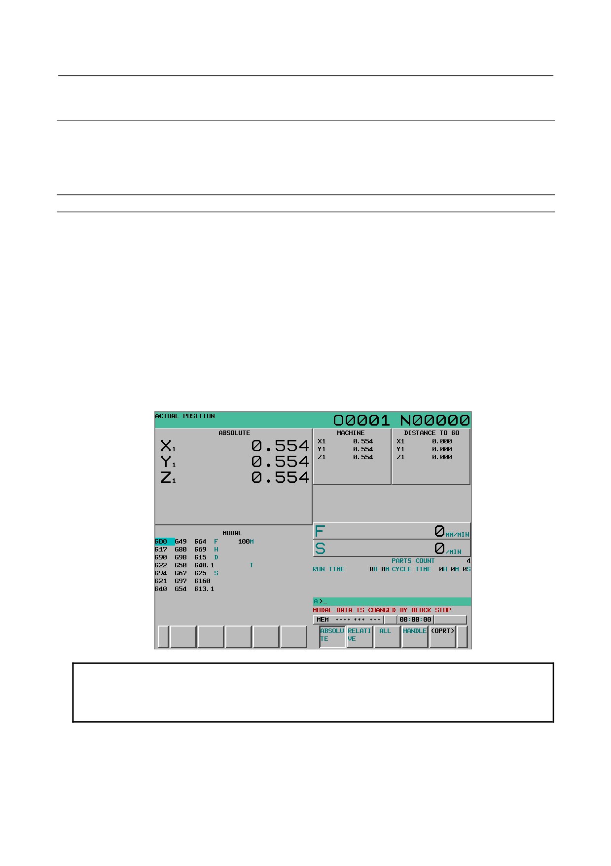
If a reset occurs during program operation, a warning saying "MODAL DATA IS CHANGED BY
BLOCK STOP" is issued. To enable or disable the warning, set bit 0 (MDW) of parameter No. 10334.
-
Warning occurrence condition
• When a reset occurs during program operation, if address G, F, H, D, T, S, M, or B (second auxiliary
function) was changed
-
Warning clear condition
• When a reset is issued
• When the <CAN> key is pressed
-
Warning displaying screen
NOTE
There is no function for acquiring or displaying a warning message in C
Language Executor. Accordingly, this warning cannot be displayed on a screen
created by the machine tool builder.
- 424 -

B-64304EN/02
OPERATION
6.SAFETY FUNCTIONS
6.5.3
Setting Screen
This section describes how to display the operation confirmation function setting screen and how to set
the individual data items on this screen.
The operation confirmation function setting screen allows you to set the following items:
• Enabling or disabling each operation confirmation function
• Effective value range for the tool offset
• Effective value range for the workpiece origin offset
T
• Effective value range for the Y-axis tool offset
• Effective value range for the work shift
6.5.3.1 Operation confirmation function setting screen
This screen displays the enable/disable setting status of the following operation confirmation functions
and lets you change their settings.
(Hereinafter, the screen is referred to as the operation confirmation
function setting screen.)
• Confirmation of incremental input
• Prohibition of the absolute input by the soft key
• Confirmation of the deletion of the program
• Confirmation of the deletion of all data
• Confirmation of a data update during the data setting process
• Display of updated modal information
• Axis status display
• Confirmation of the start from a middle block
Displaying and setting the operation confirmation function setting screen
Procedure
1
Press the
function key.
2
Press the continuous menu key
at the right edge of the screen several times until the [GUARD]
soft key is displayed.
3
Click the [GUARD] soft key. The setting screen that was displayed last with relation to any
operation confirmation function is displayed (the operation confirmation function setting screen is
the first such screen that appears after the system is restarted).
4
If any screen other than the operation confirmation function setting screen is displayed, click the
[GUARD] soft key. The operation confirmation function setting screen is displayed.
- 425 -