FANUC Series 0i-MODEL D, Series 0i Mate-MODEL D. OPERATOR'S MANUAL - page 16
6.SAFETY FUNCTIONS
OPERATION
B-64304EN/02
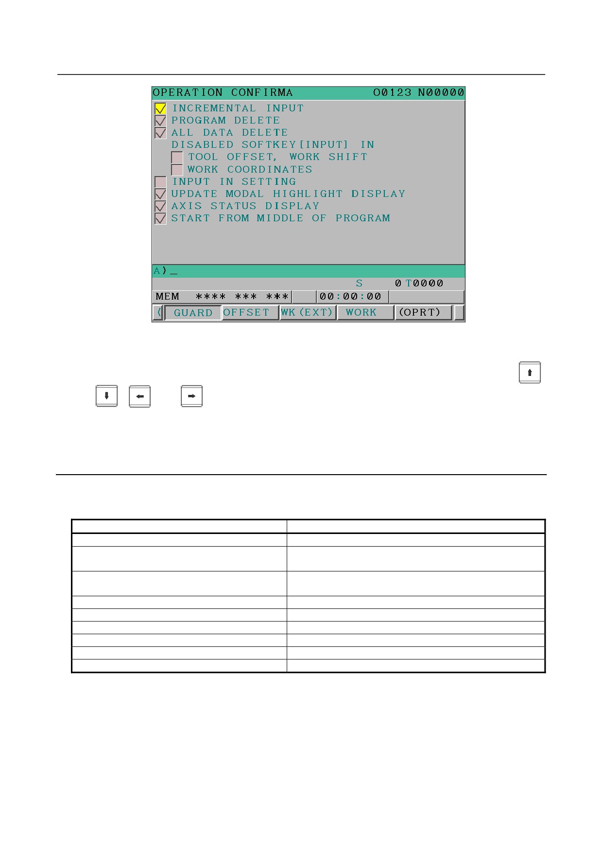
Fig. 6.5.3.1 (a) Operation confirmation function setting screen
5
In the operation confirmation function setting screen, the check box of each enabled function is
checked (✓). Move the cursor to the check box of the item you want to set, by pressing the
,
,
, and
keys.
6
Click the operation soft key [ON:1] or [OFF:0]. When you click the [ON:1] soft key, a check mark
(✓) appears in the corresponding check box, indicating that the function is enabled. When you
click the [OFF:0] soft key, the check mark disappears from the check box, indicating that the
function is disabled.
Explanation
-
Items to be set
The following table shows what is displayed for each item to be set and the corresponding functions.
Displayed item
Corresponding function
INCREMENTAL INPUT
Confirmation of incremental input
DISABLED SOFTKEY[INPUT] IN
Prohibition of the absolute input by the soft key (tool offset,
TOOL OFFSET, WORK SHIFT
Y-axis tool offset (T series), and work shift (T series))
DISABLED SOFTKEY[INPUT] IN
Prohibition of the absolute input by the soft key (workpiece
WORK COORDINATES
origin offset)
PROGRAM DELETE
Confirmation of the deletion of the program
ALL DATA DELETE
Confirmation of the deletion of all data
INPUT IN SETTING
Confirmation of a data update during the data setting process
UPDATE MODAL HIGHLIGHT DISPLAY
Display of updated modal information
AXIS STATUS DISPLAY
Axis status display
START FROM MIDDLE OF PROGRAM
Confirmation of the start from a middle block
- 426 -
B-64304EN/02
OPERATION
6.SAFETY FUNCTIONS
6.5.3.2 Tool offset range setting screen
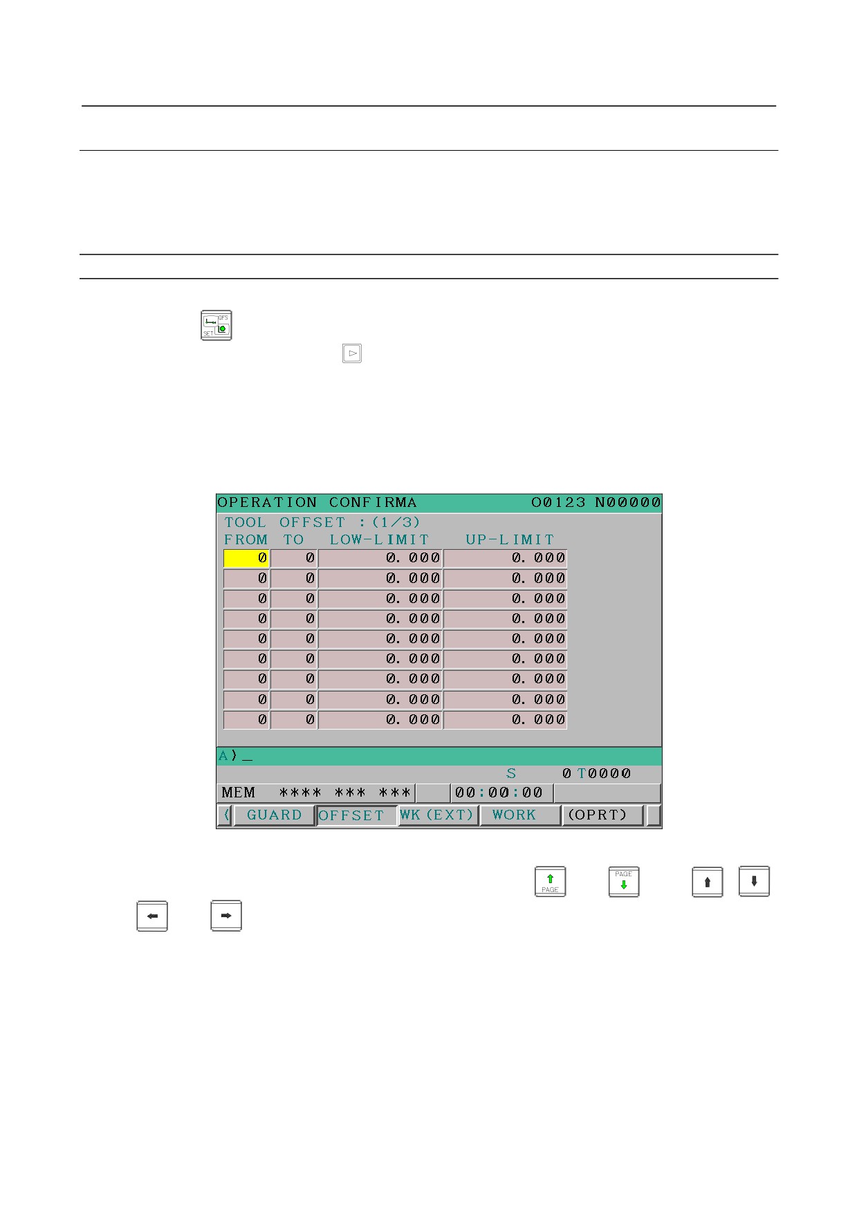
This screen displays the setting status of tool offset effective data ranges and lets you change their
settings.
(Hereinafter, the screen is referred to as the tool offset range setting screen.)
Up to 20 pairs of numbers can be specified to identify tool offset number ranges, and an effective offset
value range can be defined for each of these 20 pairs.
Displaying and setting the tool offset range setting screen
Procedure
1
Press the
function key.
2
Press the continuous menu key
at the right edge of the screen several times until the [GUARD]
soft key is displayed.
3
Click the [GUARD] soft key. The setting screen that was displayed last with relation to any
operation confirmation function is displayed (the operation confirmation function setting screen is
the first such screen that appears after the system is restarted).
4 If any screen other than the tool offset range setting screen is displayed, click the [OFFSET] soft key.
The tool offset range setting screen is displayed. What is displayed in this screen differs depending
on the system configuration described later.
Fig. 6.5.3.2 (a) Tool offset range setting screen
5
Move the cursor to the item you want to set, by using the
and
keys,
,
,
, and
keys, or the [SWITCH] soft key.
6
Press the MDI key, enter necessary data, and then click the [INPUT] soft key.
If the set effective data range is invalid for any of the reasons listed below, the input data range check is
not performed normally and the input data is rejected.
• There is a tool offset number overlap.
• The upper and lower limit values are reversed.
• The values are not effective (e.g., more pairs of offset numbers than allowed are set).
• Either of the tool offset numbers is 0.
Also, the input data range check is invalidated in the following cases.
- 427 -
6.SAFETY FUNCTIONS
OPERATION
B-64304EN/02
• Both the upper and lower limit values for the tool offset number are 0.
• The upper and lower offset limit values are identical.
Explanation
-
Control type
The setting depend on the control type shown below.
M
• Tool offset memory A (bit 6 (NGW) of parameter No. 8136 is 1)
• Tool offset memory C (bit 6 (NGW) of parameter No. 8136 is 0)
T
• Without geometry and wear offset (bit 6 (NGW) of parameter No. 8136 is 1)
• With geometry and wear offset bit 6 (NGW) of parameter No. 8136 is 0)
M
-
Settings with tool offset memory A (bit 6 (NGW) of parameter No. 8136 is 1)
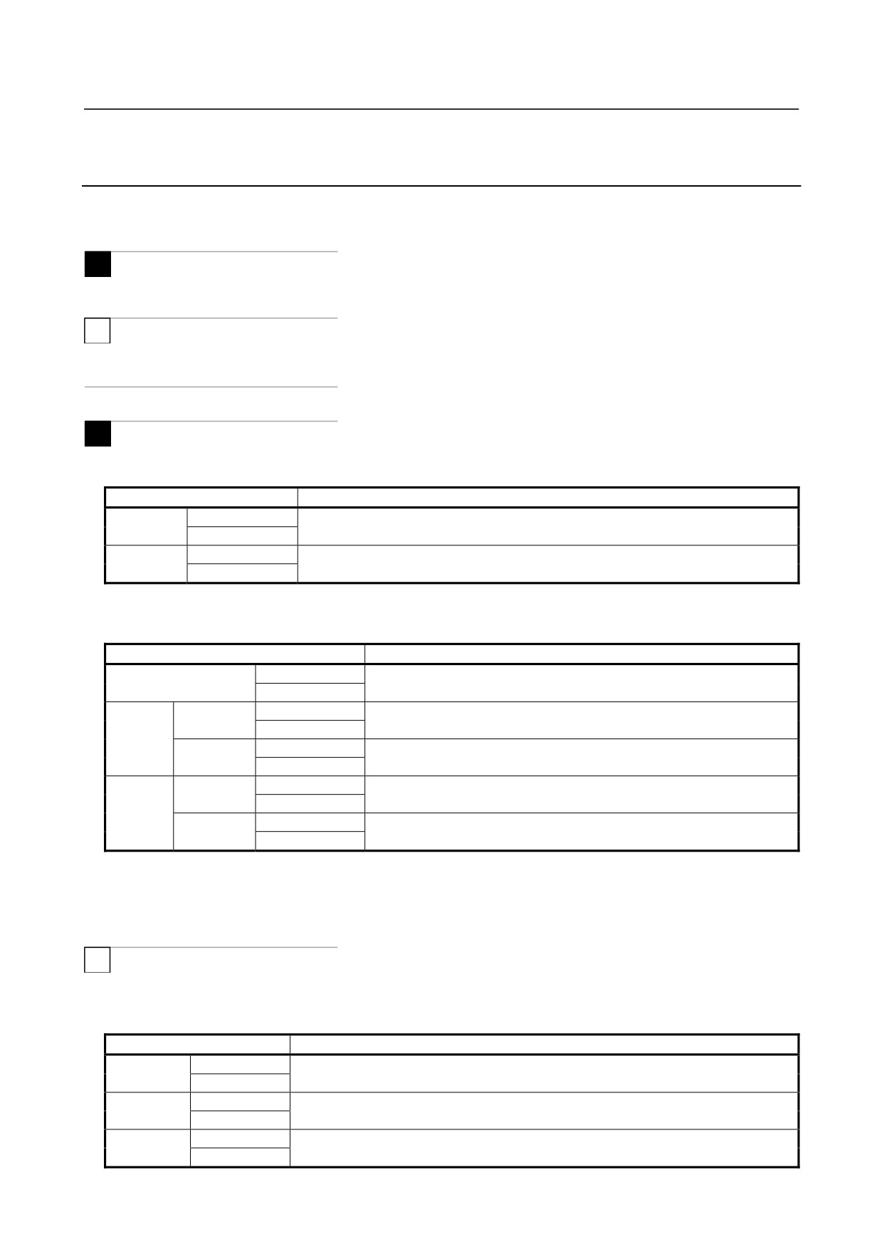
With tool offset memory A, an effective data range is specified using the following four items.
Displayed item
What to set
FROM
RANGE
Specify a tool offset number range.
TO
LOW-LIMIT
Specify a valid tool offset value range in connection with a specified tool offset
-
UP-LIMIT
number range.
-
Settings with tool offset memory C (bit 6 (NGW) of parameter No. 8136 is 0)
With tool offset memory C, an effective data range is specified using the following ten items.
Displayed item
What to set
FROM
RANGE
Specify a tool offset number range.
TO
LOW-LIMIT
Specify a valid tool offset value range for geometry length in connection
LENGTH
UP-LIMIT
with a specified tool offset number range.
GEOM
LOW-LIMIT
Specify a valid tool offset value range for geometry radius in connection
RADIUS
UP-LIMIT
with a specified tool offset number range.
LOW-LIMIT
Specify a valid tool offset value range for wear length in connection with
LENGTH
UP-LIMIT
a specified tool offset number range.
WEAR
LOW-LIMIT
Specify a valid tool offset value range for wear radius in connection with
RADIUS
UP-LIMIT
a specified tool offset number range.
In the case of this configuration, all the information needed to set an input data range cannot be displayed
in a single screen page. Set the information while switching pages using the [SWITCH] soft key. The
screen provides an indication that lets you know which part of the information is currently displayed.
T
-
Settings without geometry and wear offset (bit 6 (NGW) of parameter No. 8136
is 1)
Without geometry/wear offset, an effective data range is specified using the following eight items.
Displayed item
What to set
FROM
RANGE
Specify a tool offset number range.
TO
LOW-LIMIT
Specify a valid tool offset value range for the X-axis in connection with a specified tool
X
UP-LIMIT
offset number range.
LOW-LIMIT
Specify a valid tool offset value range for the Z-axis in connection with a specified tool
Z
UP-LIMIT
offset number range.
- 428 -
B-64304EN/02
OPERATION
6.SAFETY FUNCTIONS
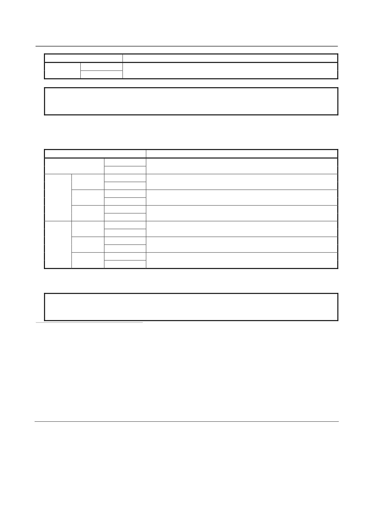
Displayed item
What to set
LOW-LIMIT
Specify a valid tool offset value range for tool-nose radius in connection with a
RADIUS
UP-LIMIT
specified tool offset number range.
NOTE
The radius items are not displayed when tool-nose radius compensation is not
provided (bit 7 (NCR) of parameter No. 8136 is 1).
-
Settings with geometry and wear offset (bit 6 (NGW) of parameter No. 8136 is
0)
With geometry/wear offset, an effective data range is specified using the following 14 items.
Displayed item
What to set
FROM
RANGE
Specify a tool offset number range.
TO
LOW-LIMIT
Specify a valid tool offset value range for the geometry X-axis in connection
X
UP-LIMIT
with a specified tool offset number range.
LOW-LIMIT
Specify a valid tool offset value range for the geometry Z-axis in connection
GEOM
Z
UP-LIMIT
with a specified tool offset number range.
LOW-LIMIT
Specify a valid tool offset value range for geometry tool-nose radius in
RADIUS
UP-LIMIT
connection with a specified tool offset number range.
LOW-LIMIT
Specify a valid tool offset value range for the wear X-axis in connection with
X
UP-LIMIT
a specified tool offset number range.
LOW-LIMIT
Specify a valid tool offset value range for the wear Z-axis in connection with
WEAR
Z
UP-LIMIT
a specified tool offset number range.
LOW-LIMIT
Specify a valid tool offset value range for wear tool-nose radius in
RADIUS
UP-LIMIT
connection with a specified tool offset number range.
In the case of this system, all the information needed to set an input data range cannot be displayed in a
single screen page. Set the information while switching pages using the [SWITCH] soft key. The
screen provides an indication that lets you know which part of the information is currently displayed.
NOTE
The radius items are not displayed when tool-nose radius compensation is not
provided (bit 7 (NCR) of parameter No. 8136 is 1).
-
Example of setting an input data range
For example, suppose that the following values are set with offset memory A (M series).
FROM : TO LOW-LIMIT : UP-LIMIT
1 : 20
0.000 : 100.000
In this case, the tool offset input screen accepts only offset values from 0.000 to 100.000 for offset
numbers 1 to 20.
If you attempt to input any other value, the warning message "DATA IS OUT OF RANGE" is displayed.
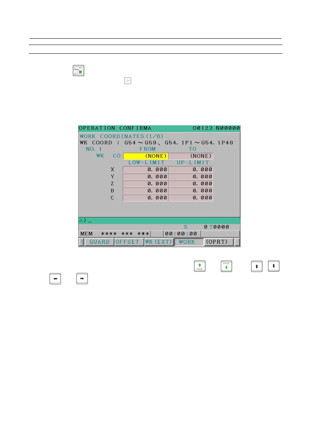
6.5.3.3 Workpiece origin offset range setting screen
This screen displays the setting status of workpiece origin offset and external workpiece origin offset
effective data ranges and lets you change their settings.
(Hereinafter, the screen is referred to as the
workpiece origin offset range setting screen.)
Up to six pairs of values can be specified to identify workpiece coordinate ranges for the workpiece
origin offset, and an effective offset value range can be defined for each of the axes of these six pairs.
As for the external workpiece origin offset, an effective offset value range can be specified for each axis.
- 429 -
6.SAFETY FUNCTIONS
OPERATION
B-64304EN/02
Displaying and setting the workpiece origin offset range setting screen
Procedure
1
Press the
function key.
2
Press the continuous menu key
at the right edge of the screen several times until the [GUARD]
soft key is displayed.
3
Click the [GUARD] soft key. The setting screen that was displayed last with relation to any
operation confirmation function is displayed (the operation confirmation function setting screen is
the first such screen that appears after the system is restarted).
4
If any screen other than the workpiece origin offset range setting screen is displayed, click the
[WORK] soft key. The workpiece origin offset range setting screen is displayed.
Fig. 6.5.3.3 (a) Workpiece origin offset range setting screen
5
Move the cursor to the item you want to set, by using the
and
keys,
,
,
, and
keys, or the [SWITCH] soft key.
6
Press the MDI key, enter necessary data, and then click the [INPUT] soft key.
If the set effective data range is invalid for any of the reasons listed below, the input data range check is
not performed normally and the input data is rejected.
• There is a workpiece coordinate overlap.
• The upper and lower limit values are reversed.
• The values are not effective (e.g., an invalid workpiece coordinate system is set).
• The upper limit value is set for the workpiece coordinate system when 0 is set for the lower limit
value.
Also, the input data range check is invalidated in the following cases.
• Both the upper and lower limit values for the workpiece coordinate system are 0.
• The upper and lower limit values for each offset are identical.
- 430 -
B-64304EN/02
OPERATION
6.SAFETY FUNCTIONS
Explanation
-
What to set for the workpiece origin offset
For the workpiece origin offset, an effective data range is specified using the following four items.
Displayed item
What to set
FROM
RANGE
Specify a workpiece coordinate system range.
TO
AXIS
LOW-LIMIT
Specify a valid offset value range in connection with a specified workpiece coordinate
NAME
UP-LIMIT
system range.
-
What to set for the external workpiece origin offset
For the external workpiece origin offset, an effective data range is specified using the following two
items.
Displayed item
What to set
AXIS
LOW-LIMIT
Specify a valid external workpiece origin offset value range on each axis.
NAME
UP-LIMIT
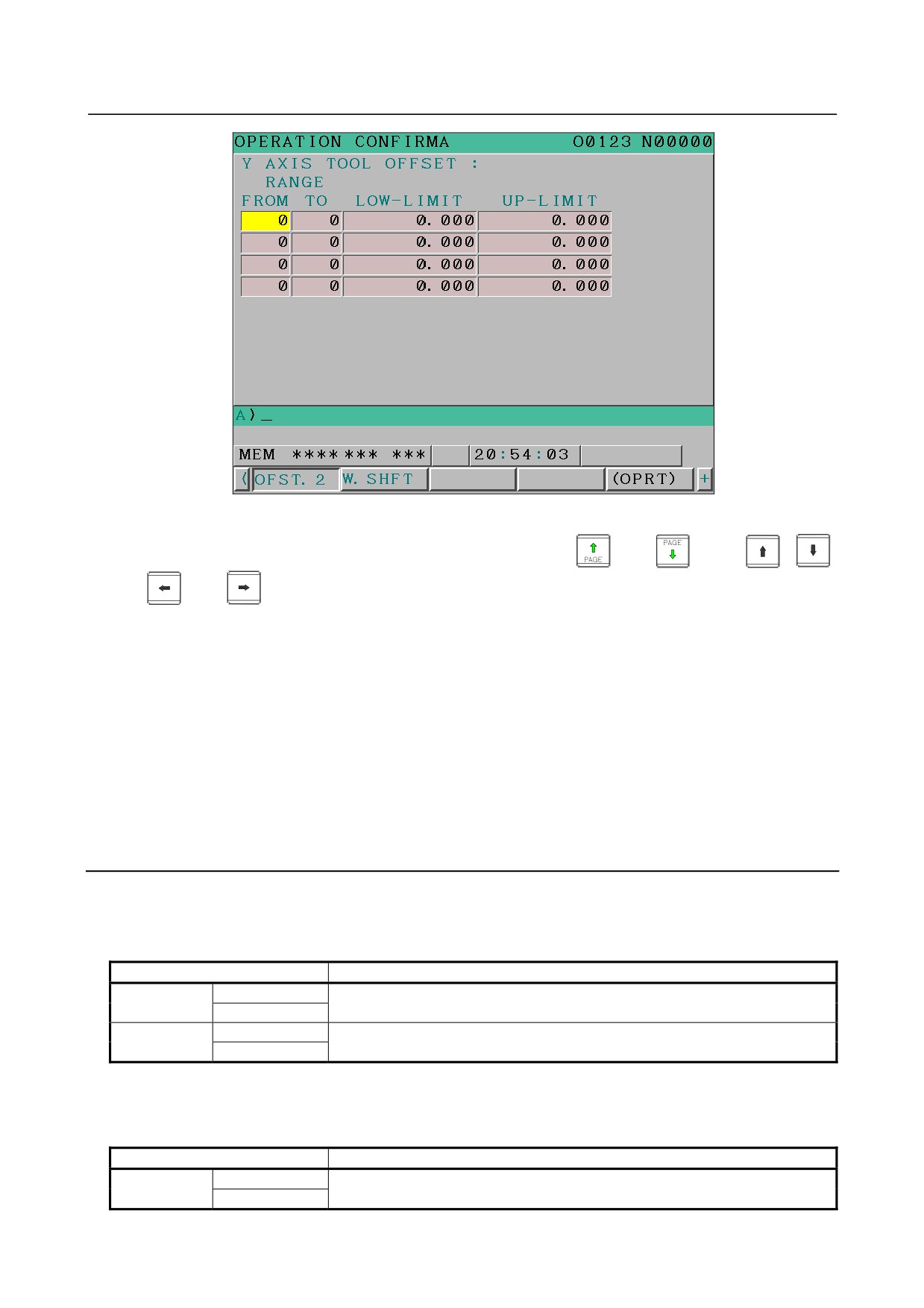
6.5.3.4 Y-axis tool offset range setting screen
T
In the case of a T series system, this screen displays the setting status of Y-axis tool offset effective data
ranges and lets you change their settings.
(Hereinafter, the screen is referred to as the Y-axis tool offset
range setting screen.)
Up to four pairs of values can be specified to identify Y-axis tool offset number ranges, and an effective
offset value range can be defined for each of these four pairs.
Displaying and setting the Y-axis tool offset range setting screen
Procedure
1
Press the
function key.
2
Press the continuous menu key
at the right edge of the screen several times until the [GUARD]
soft key is displayed.
3
Click the [GUARD] soft key. The setting screen that was displayed last with relation to any
operation confirmation function is displayed (the operation confirmation function setting screen is
the first such screen that appears after the system is restarted).
4
If any screen other than the Y-axis tool offset range setting screen is displayed, click the [OFST.2]
soft key. The Y-axis tool offset range setting screen is displayed. What is displayed in this screen
differs depending on such factors as whether tool geometry/wear offsets are present.
- 431 -
6.SAFETY FUNCTIONS
OPERATION
B-64304EN/02
Fig. 6.5.3.4 (a) Y-axis tool offset range setting screen
5
Move the cursor to the item you want to set, by using the
and
keys,
,
,
, and
keys, or the [SWITCH] soft key.
6
Press the MDI key, enter necessary data, and then click the [INPUT] soft key.
If the set effective data range is invalid for any of the reasons listed below, the input data range check is
not performed normally and the input data is rejected.
• There is a tool offset number overlap.
• The upper and lower limit values are reversed.
• The values are not effective (e.g., more pairs of offset numbers than allowed are set).
• Either of the tool offset numbers is 0.
Also, the input data range check is invalidated in the following cases.
• Both the upper and lower limit values for the tool offset number are 0.
• The upper and lower offset limit values are identical.
Explanation
-
Settings without geometry and wear offset (bit 6 (NGW) of parameter No. 8136
is 1)
Without geometry/wear offsets, an effective data range is specified using the following four items.
Displayed item
What to set
FROM
RANGE
Specify a Y-axis tool offset number range.
TO
LOW-LIMIT
Specify a valid tool offset value range in connection with a specified Y-axis tool
-
UP-LIMIT
offset number range.
-
Settings with geometry and wear offset (bit 6 (NGW) of parameter No. 8136 is
0)
With geometry/wear offsets, an effective data range is specified using the following six items.
Displayed item
What to set
FROM
RANGE
Specify a Y-axis tool offset number range.
TO
- 432 -
B-64304EN/02
OPERATION
6.SAFETY FUNCTIONS
Displayed item
What to set
LOW-LIMIT
Specify a valid tool offset value range for geometry in connection with a specified
GEOM
UP-LIMIT
Y-axis tool offset number range.
LOW-LIMIT
Specify a valid tool offset value range for wear in connection with a specified
WEAR
UP-LIMIT
Y-axis tool offset number range.
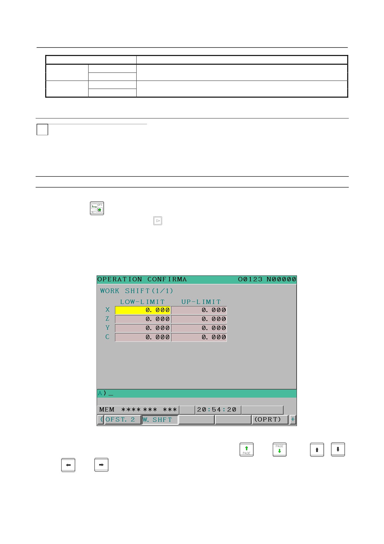
6.5.3.5 Workpiece shift range setting screen
T
In the case of a T series system, this screen displays the setting status of shift effective data ranges of
workpiece shift and lets you change their settings.
(Hereinafter, the screen is referred to as the
workpiece shift range setting screen.)
An workpiece shift value range can be specified for each axis.
Displaying and setting workpiece shift input ranges
Procedure
1
Press the
function key.
2
Press the continuous menu key
at the right edge of the screen several times until the [GUARD]
soft key is displayed.
3
Click the [GUARD] soft key. The setting screen that was displayed last with relation to any
operation confirmation function is displayed (the operation confirmation function setting screen is
the first such screen that appears after the system is restarted).
4
If any screen other than the workpiece shift range setting screen is displayed, click the [WORK
SHIFT] soft key. The workpiece shift range setting screen is displayed.
Fig. 6.5.3.5 (a) Workpiece shift range setting screen
5
Move the cursor to the item you want to set, by using the
and
keys,
,
,
, and
keys, or the [SWITCH] soft key.
6
Press the MDI key, enter necessary data, and then click the [INPUT] soft key.
If the set effective data range is invalid for any of the reasons listed below, the input data range check is
not performed normally and the input data is rejected.
- 433 -

6.SAFETY FUNCTIONS
OPERATION
B-64304EN/02
• The upper and lower limit values are reversed.
Also, the input data range check is invalidated in the following cases.
• The upper and lower workpiece shift limit values are identical.
Explanation
-
What to set for the workpiece shift
For the workpiece shift, an effective data range is specified using the following two items.
Displayed item
What to set
AXIS
LOW-LIMIT
Specify a valid workpiece shift value range on each axis.
NAME
UP-LIMIT
- 434 -
7.ALARM AND SELF-DIAGNOSIS
B-64304EN/02
OPERATION
FUNCTIONS
7 ALARM AND SELF-DIAGNOSIS
FUNCTIONS
When an alarm occurs, the corresponding alarm screen appears to indicate the cause of the alarm. The
causes of alarms are classified by error codes and number. Up to 50 previous alarms can be stored and
displayed on the screen (alarm history display).
The system may sometimes seem to be at a halt, although no alarm is displayed. In this case, the system
may be performing some processing. The state of the system can be checked using the self-diagnosis
function.
7.1
ALARM DISPLAY
Explanation
-
Alarm screen
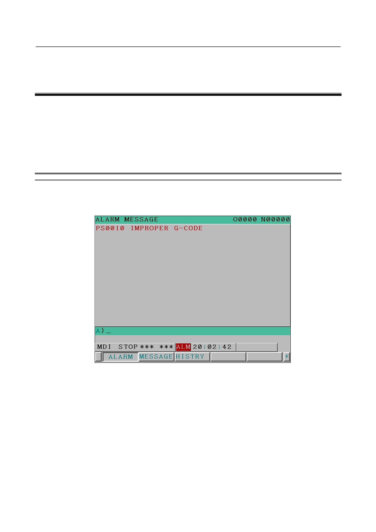
If an alarm occurs, the alarm screen (error code and number) appears to indicate the cause. Alarms are
classified by an error code and number.
Fig. 7.1 (a) Alarm screen (example for the 8.4-inch display unit)
Display wrapping
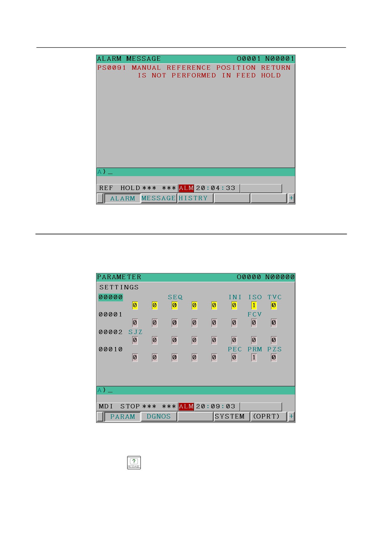
If an alarm message does not fit one line, the display is wrapped and the rest of the message begin at the
start position on the next line.
- 435 -
7. ALARM AND SELF-DIAGNOSIS
FUNCTIONS
OPERATION
B-64304EN/02
Fig. 7.1(b) Display wrapping (example for the 8.4-inch display unit)
7.1.1
Operation
-
How to display the alarm screen
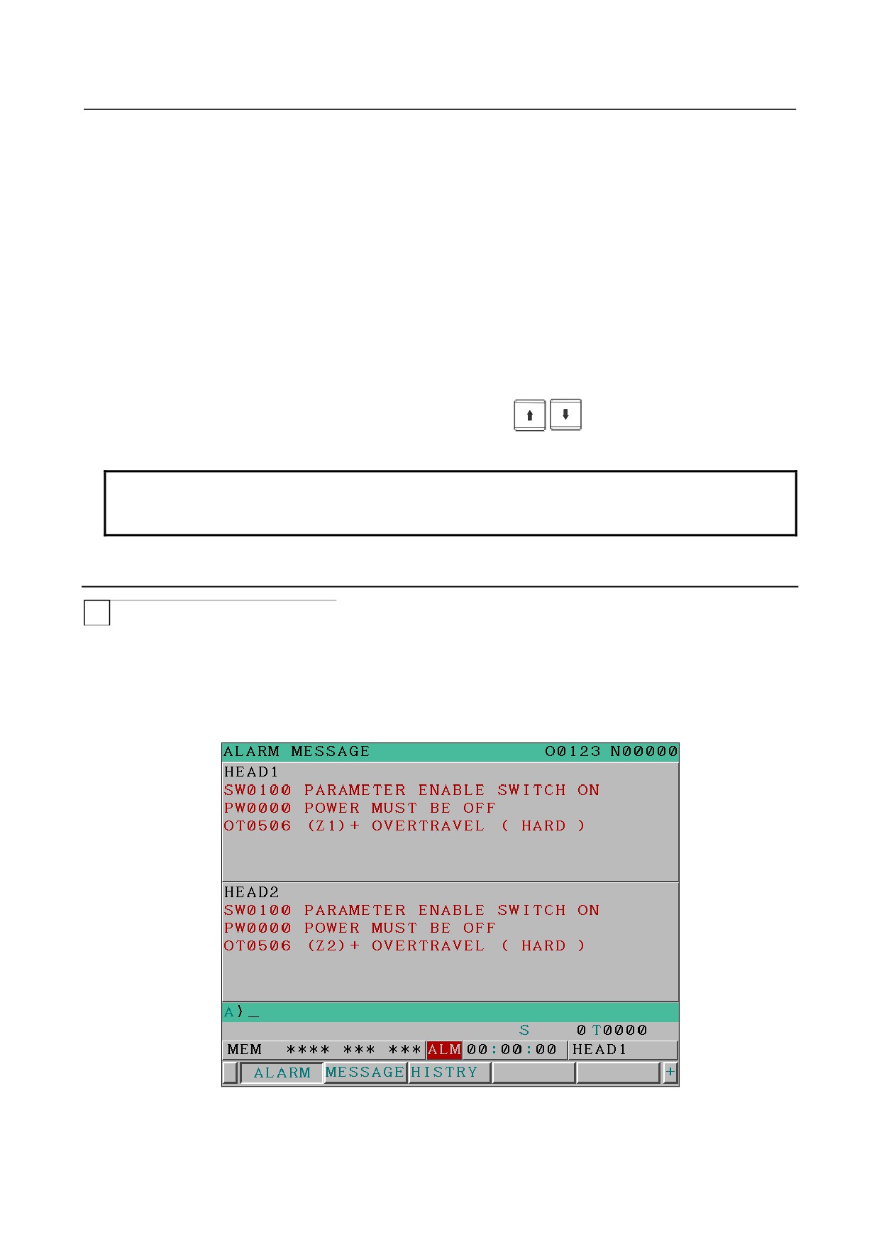
In some cases, no switching occurs to the alarm screen, and “ALM” is displayed on the bottom of the
current screen (for example, if bit 7 (NPA) of parameter No. 3111 = 1).
Fig. 7.1 (c) Parameter screen (example for the 8.4-inch display unit)
In this case, display the alarm screen by following the steps below.
1
Press the function key
2
Press the soft key [ALARM].
3
The page change key can be used to switch between pages.
- 436 -
7.ALARM AND SELF-DIAGNOSIS
B-64304EN/02
OPERATION
FUNCTIONS
-
Releasing alarm
The cause of an alarm can be determined from the error code, number, and associated message. To
release the alarm, generally correct the cause, then press the reset key.
-
Error code and number
The type of an alarm is indicated by an error code and number.
Example: PS0010, SV0004, etc.
For details, see Appendix G, "ALARMS".
Screen scrolling
If alarm information does not fit one screen, the page keys (PageDown and PageUp) can be used to scroll
the alarm information screen by screen.
Line scrolling
If alarm information does not fit one screen, the cursor keys
can be used to scroll the alarm
information alarm by alarm.
NOTE
In simultaneous 2-path display, the alarm displays of both the paths are
subjected to screen/line scrolling simultaneously.
7.1.2
Alarm Display in a 2-Path System
T
2-path concurrent display
Alarms for two paths are displayed concurrently in a 2-path system.
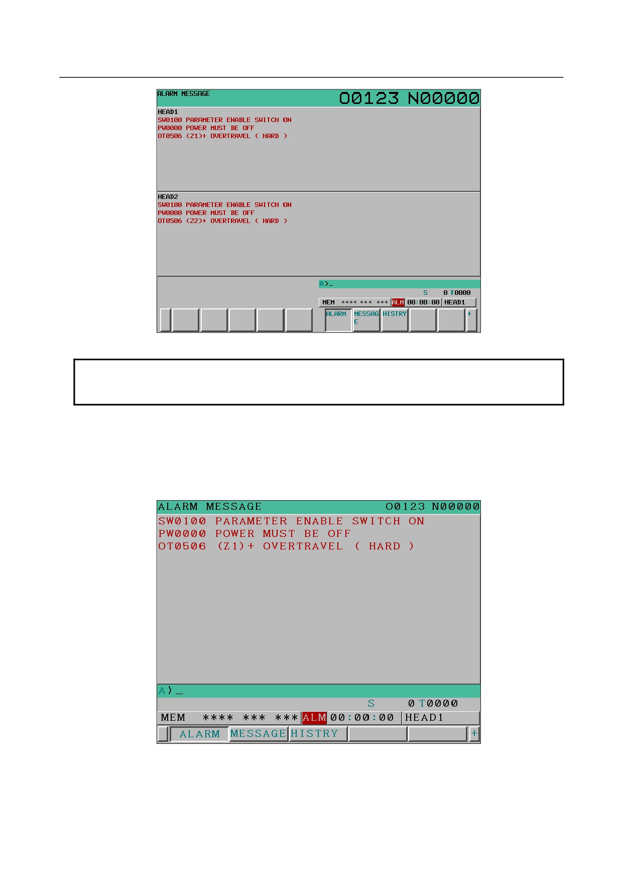
The path name is displayed on the first line of each screen.
Display order change
Parameter No. 13130 can be set to change the display order of two paths.
Fig. 7.1.2(a)
2-path display on the alarm display screen (8.4-inch display unit)
- 437 -
7. ALARM AND SELF-DIAGNOSIS
FUNCTIONS
OPERATION
B-64304EN/02
Fig. 7.1.2(b)
2-path display on the alarm display screen (10.4-inch display unit)
NOTE
If an arbitrary name is set (by parameters Nos. 3141 to 3147) for each path, the
arbitrary name is displayed at the upper left of each split screen instead.
Single path display
For a 2-path system, if bit 2 of parameter No. 3193 is set to 1, it is possible to switch from 2-path
concurrent display to single path display.
Alarms for the selected path are displayed in the full screen mode.
Fig. 7.1.2(c) Alarm screen (single path display for the 8.4-inch display unit)
- 438 -
7.ALARM AND SELF-DIAGNOSIS
B-64304EN/02
OPERATION
FUNCTIONS
7.2
ALARM HISTORY DISPLAY
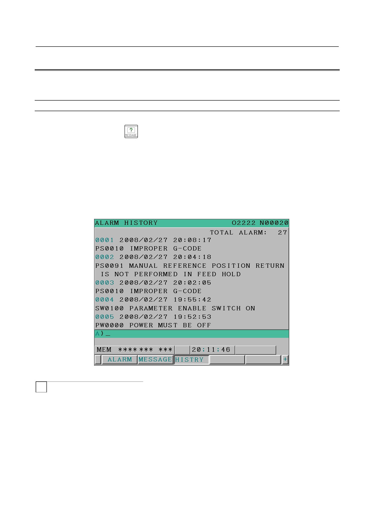
Up to 50 alarms issued by the CNC including the latest alarm are stored and displayed on the screen.
The display procedure is explained below.
Alarm history display
Procedure
1
Press the function key
2
Press the soft key [HISTRY].
An alarm history is displayed.
The following information is displayed:
<1> Date and time of alarm issuance
<2> Alarm type
<3> Alarm number
<4> Alarm message (sometimes not displayed depending on the alarm)
<5> Number of recorded alarms
3
You can change pages by using the page key.
Fig. 7.2 (a) Alarm history screen (example for the 8.4-inch display unit)
T
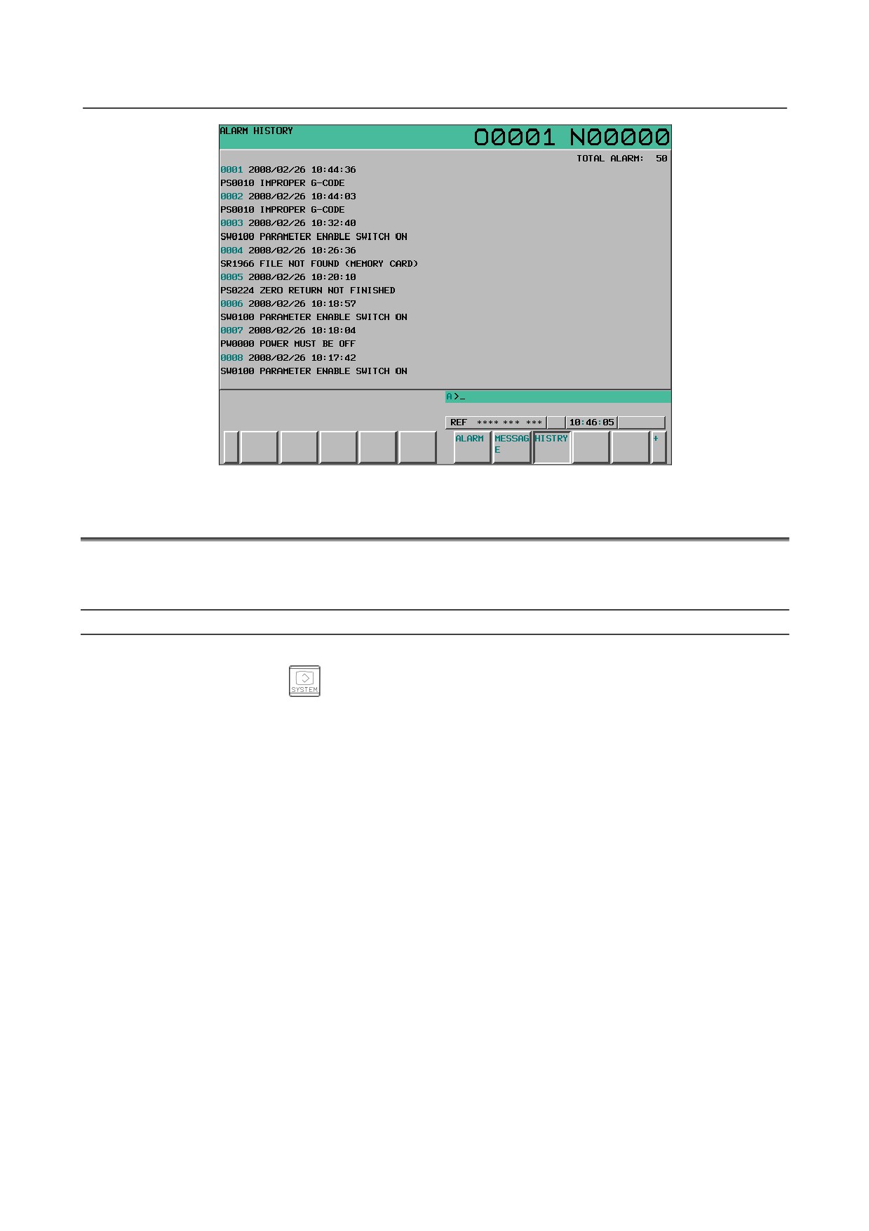
For a 2-path system, alarms that were issued on both paths are displayed on one screen, regardless of the
selected path.
Each history data is preceded by the path on which the alarm was issued.
A total of 50 alarms issued on both paths are recorded.
- 439 -
7. ALARM AND SELF-DIAGNOSIS
FUNCTIONS
OPERATION
B-64304EN/02
Fig. 7.2 (b) Alarm history screen (or a 2-path system, example of the 10.4-inch display unit)
7.3
CHECKING BY DIAGNOSTIC DISPLAY
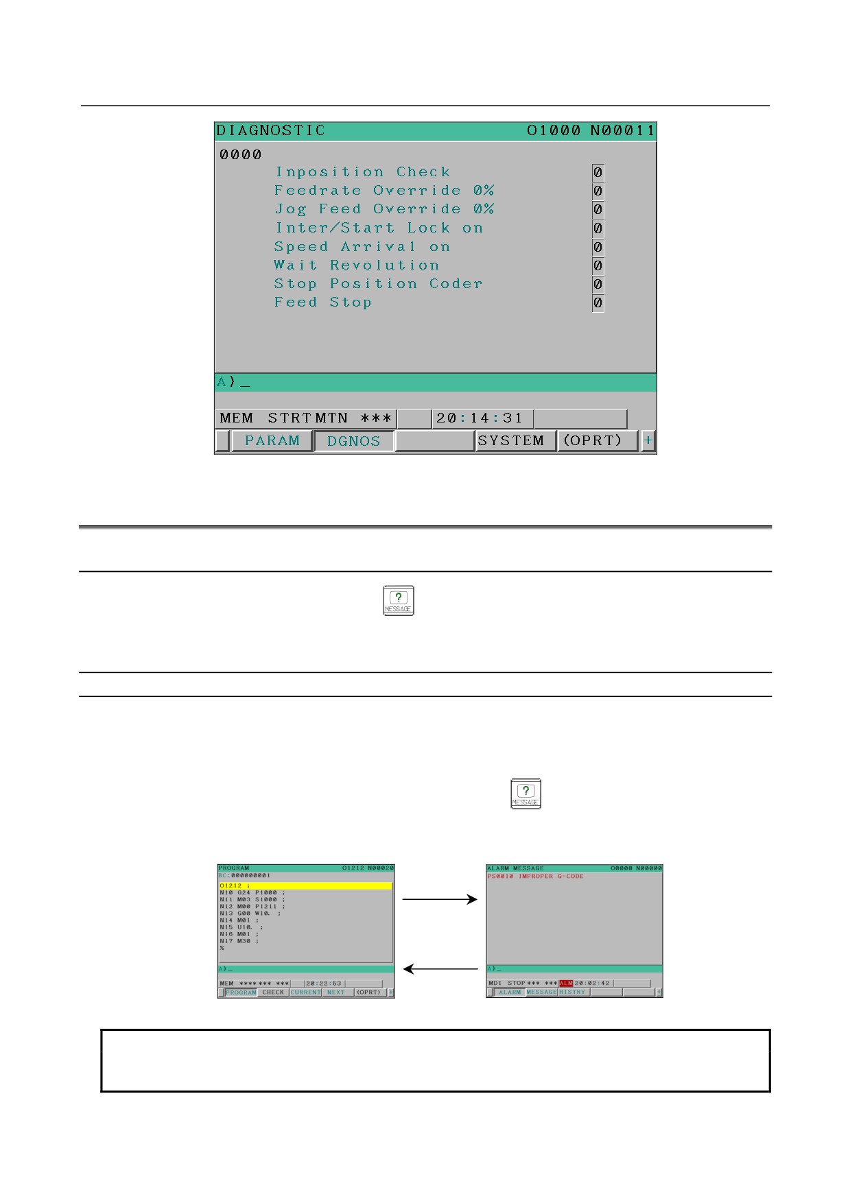
The system may sometimes seem to be at a halt, although no alarm has occurred. In this case, the system
may be performing some processing. Diagnostic display can be used to check the system status.
Procedure for Diagnostic display
Procedure
1
Press the function key
2
Press the soft key [DGNOS].
3
The diagnosis screen has more than 1 pages. Select the screen by the following operation.
(1) Change the page by the page change key.
(2) Method by soft key
• Key input the number of the diagnosis data to be displayed.
• Press the soft key [NO.SRH].
- 440 -
7.ALARM AND SELF-DIAGNOSIS
B-64304EN/02
OPERATION
FUNCTIONS
Fig. 7.3 (a) Diagnostic display (example for the 8.4-inch display unit)
7.4
RETURN FROM THE ALARM SCREEN
7.4.1
Return from the Alarm Screen
When alarms are cleared or function key
is pressed on the alarm screen, the screen displayed
before the alarm screen appears.
To enable this function, set bit 4 (ADC) of parameter No. 11302 is set to 1.
Switching between screens when alarms are cleared
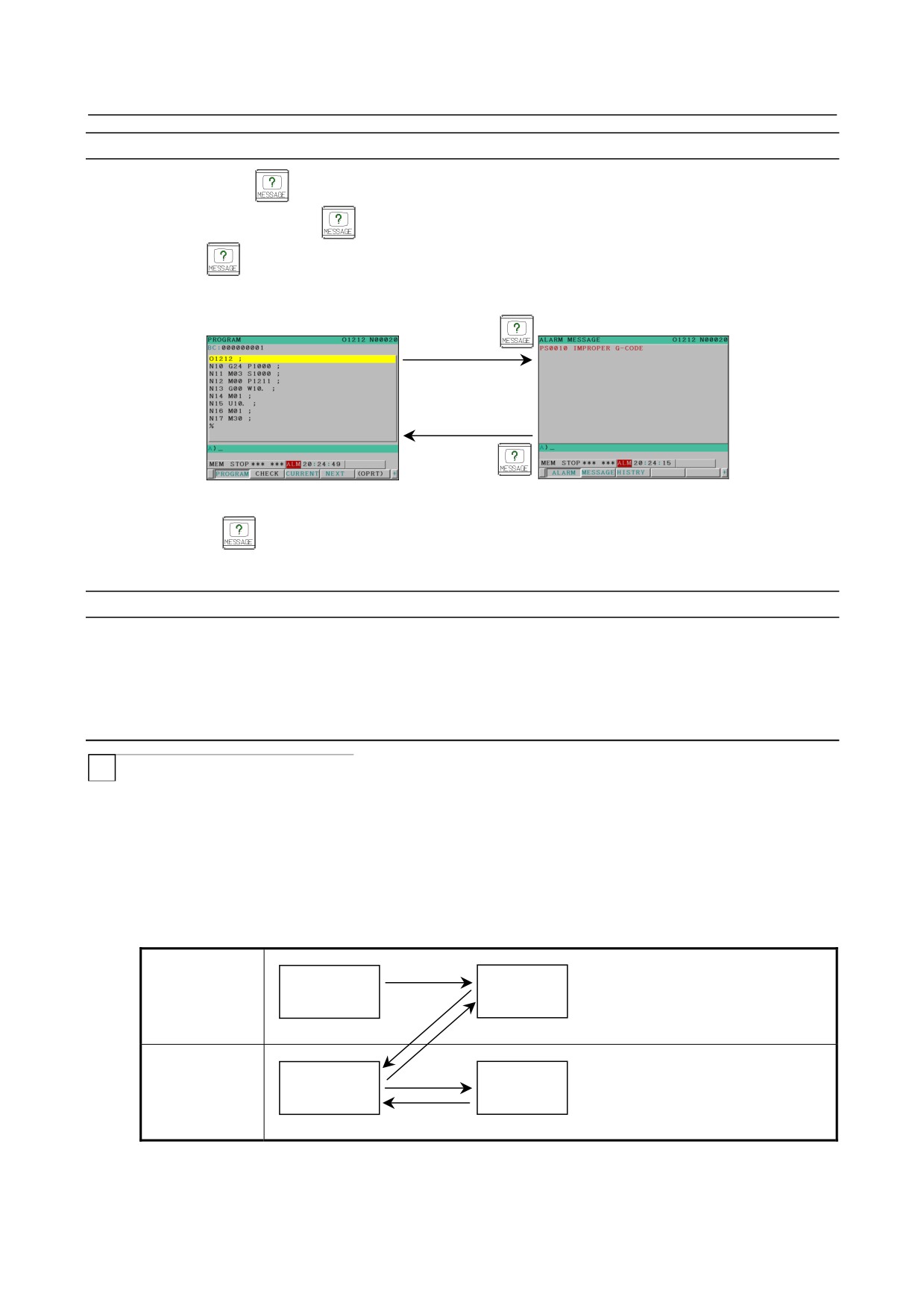
When all alarms are cleared on the alarm screen, the screen displayed before the alarm screen appears
again.
When the alarm screen was displayed automatically due to occurrence of an alarm, the screen displayed
immediately before the alarm appears again.
When the alarm screen was displayed by pressing function key
during occurrence of an alarm, the
screen displayed immediately before the alarm appears again.
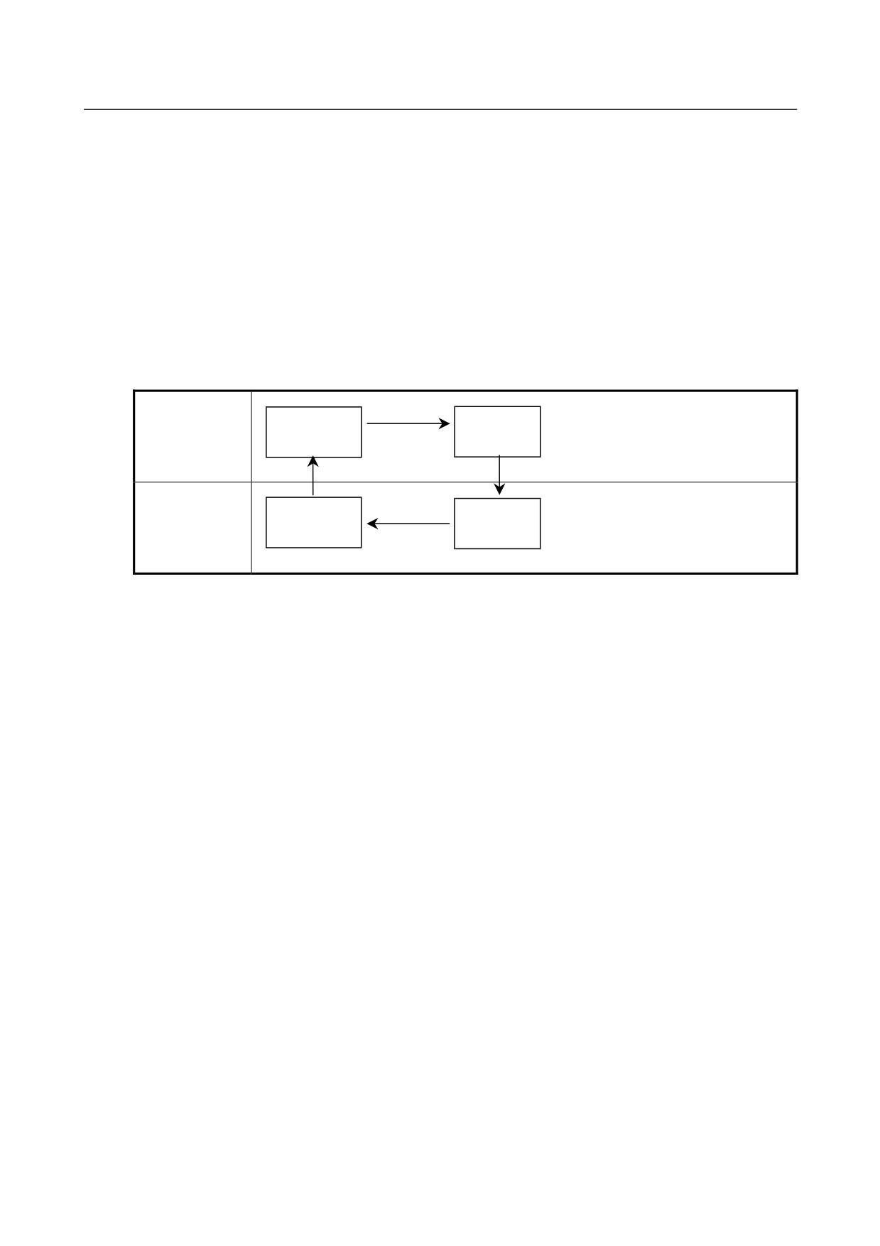
(Example)
Occurrence of
an alarm
Clearing of
alarm
PROGRAM screen
ALARM screen
NOTE
Even if alarms are cleared when the alarm screen is not displayed, the current
screen is not changed.
- 441 -
7. ALARM AND SELF-DIAGNOSIS
FUNCTIONS
OPERATION
B-64304EN/02
Switching between screens by the function key
When function key
is pressed on the alarm screen, the screen displayed before the alarm screen
appears. Press function key
to switch to the alarm screen for checking for alarms and then press
function key
to return to the previous screen.
(Example)
Function key
Function key
PROGRAM screen
ALARM screen
If function key
is pressed when the alarm screen was displayed automatically due to occurrence of
an alarm, the screen displayed before the alarm screen appears again.
Restrictions
• Switching to the interactive macro screen is not performed.
• The screens to which the alarm screen can be switched are only the screen selected by the chapter
selection soft key.
7.4.2
Relationship with Other Functions (For 2-Path Control)
T
Relationship between the screen switching function and a return from the
alarm screen during switching between paths
(1) When bit 5 (PSC) of parameter No. 3208 is set to 0, if paths are switched by the path switching
signal, the screen last selected in the path appears again.
At this time, even if a return from the alarm screen to the previous screen is performed in one path, a
return is not performed in the another path and the alarm screen remains displayed.
(Example)
<1>
Offset
Alarm
Path 1
<2>
<5>
<3>
Position
Alarm
Path 2
<4>
<1> When the message key is pressed on the offset screen of path 1, the alarm screen (path 1)
appears.
- 442 -
7.ALARM AND SELF-DIAGNOSIS
B-64304EN/02
OPERATION
FUNCTIONS
<2> When switching to path 2 is performed on the alarm screen of path 1, the position screen of
path 2 appears (when the screen last displayed in path 2 is the position screen).
<3> When the message key is pressed on the position screen of path 2, the alarm screen (path 2)
appears.
<4> When the alarm is cleared or the message key is pressed on the alarm screen of path 2, a return
to the position screen (path 2) is performed.
<5> When switching to path 1 is performed, the alarm screen (path 1) appears.
(2) When PSC of parameter No. 3208 is set to 1, if paths are switched by the path switching signal, the
screen displayed immediately before the path switching appears again.
At this time, if a return from the alarm screen to the previous screen is performed in one path, the
screen of the path in which a return was performed appears in the other path.
(Example)
<1>
Offset
Alarm
Path 1
<2>
<4>
Position
Alarm
Path 2
<3>
<1> When the message key is pressed on the offset screen of path 1, the alarm screen (path 1)
appears.
<2> When switching to path 2 is performed on the alarm screen of path 1, the alarm screen (path 2)
appears.
<3> When the alarm is cleared on the alarm screen of path 2, the offset screen (path 2) appears.
<4> When switching to path 1 is performed, the offset screen of path 1 appears.
- 443 -
8.DATA INPUT/OUTPUT
OPERATION
B-64304EN/02
8 DATA INPUT/OUTPUT
Information stored in external I/O devices can be read into the CNC, and information can be written into
external I/O devices.
External I/O devices include memory cards that can be mounted to the memory card interface located on
the left side of the display unit and personal computers and data servers that can be connected via
embedded Ethernet.
The following types of data can be input and output.
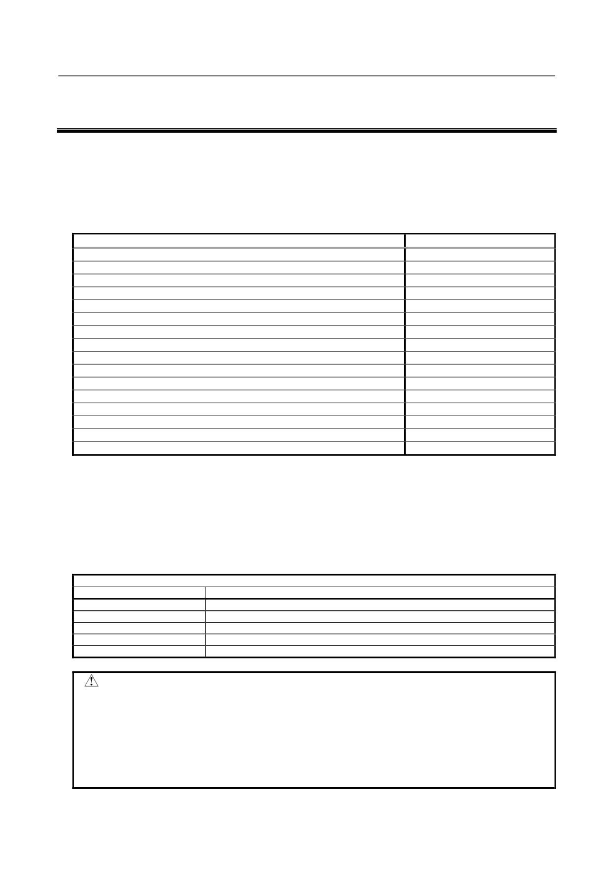
Data type
Default file name
Program
ALL-PROG.TXT
Offset data
TOOLOFST.TXT
Parameter
CNC-PARA.TXT
Pitch error compensation data
PITCH.TXT
Custom macro common variable
MACRO.TXT
Workpiece coordinate system data
EXT_WKZ.TXT
Operation history data
OPRT_HIS.TXT
Maintenance information
MAINTINF.TXT
Periodic maintenance data (periodic maintenance: status screen)
MAINTENA.TXT
System configuration data
SYS-CONF.TXT
PMC signal protect
DIDOENBL.TXT
Servo/spindle information
SV_SP_ID.TXT
Machine system name data (periodic maintenance: machine system screen)
MAINTEMC.TXT
Servo waveform diagnosis
WAVE-DGN.TXT
Tool geometry data (Interference check for each path) (T series)
TOOL-FRM.TXT
P code variable (macro executor)
PCODE.TXT
The above types of data can be input and output on the screens for displaying and setting those types of
data.
If NC data such as programs and parameters is to be written to a memory card, and if a file with the same
name already exists, it is possible to select whether to overwrite the existing file or cancel writing with
appropriate operation.
The external I/O device set in parameter No. 0020 is selected. See the table below for details.
Correspondence between settings and input/output units
Setting
Description
0,1
RS-232-C serial port 1
2
RS-232-C serial port 2
4
Memory card interface
5
Data server interface
9
Embedded Ethernet interface
WARNING
1 Always use ISO codes for input/output except when ASCII code data is to be
input.
ISO code input/output is enabled for memory cards and data servers by setting,
respectively, bit 0 (ISO) of parameter No. 0139 and bit 0 (ISO) of parameter No.
0908 to “1”.
2 ASCII data input/output is risky because ASCII data does not contain parity
information and therefore any data error cannot be detected.
- 444 -
B-64304EN/02
OPERATION
8.DATA INPUT/OUTPUT
CAUTION
1 This control unit supports the use of a Memory card as an input/output device.
The Flash ATA card is available:
See the order list for details of the supported Memory card types.
2 On a Memory card, only those files that are in the root directory can be accessed
for display, reading, and writing. Those in subdirectories cannot be used.
3 The time required to read or write each data item varies depending on the
Memory card type, the status of use, and other factors.
4 For flash ATA cards, only those recommended by FANUC are available.
5 When formatting a flash ATA card, use the quick formatting method, which
clears the file allocation table and the directory information on the root directory.
An unformatted flash ATA card needs to be formatted in FAT16 with a PC or the
like. (A FAT32-formatted ATA card cannot be recognized.)
NOTE
External I/O devices can handle file names of up to 12 characters each.
8.1
OVERWRITING FILES ON A MEMORY CARD
Screen display
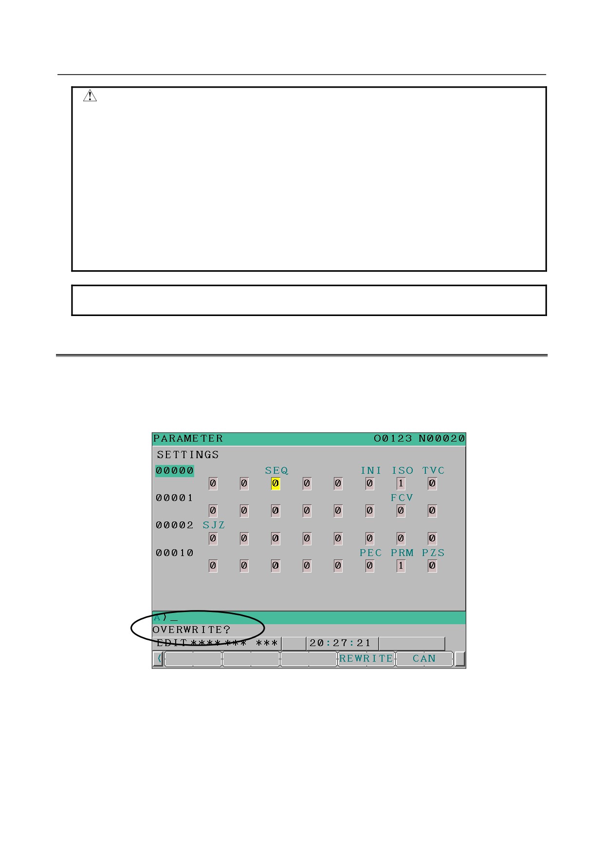
When an attempt is made to output NC data to a memory card, and if the specified file name or the default
file name is the same as an existing file name on the memory card, a confirmation message
"OVERWRITE?" appears.
Fig. 8.1 (a) Screen display example
Procedure
On the output screen for the desired function, perform the following operation.
1
Press the soft key [F OUTPUT].
2
Press the soft key [EXEC]. If a file with the same name does not exist on the memory card, the file is
output in this step.
- 445 -
8.DATA INPUT/OUTPUT
OPERATION
B-64304EN/02
3
If a file with the same name exists on the memory card, soft keys [REWRITE] and [CAN] appear.
Pressing the soft key [REWRITE] causes the file to be overwritten.
Pressing the soft key [CAN] causes output to be canceled.
Example) Output from the parameter screen
1
Press the function key
2
Press the soft key [PARAMETER].
3
Enter the EDIT mode or state emergency stop.
4
Press the soft key [(OPRT)].
5
For 8.4-inch display unit, press the continuous menu key
6
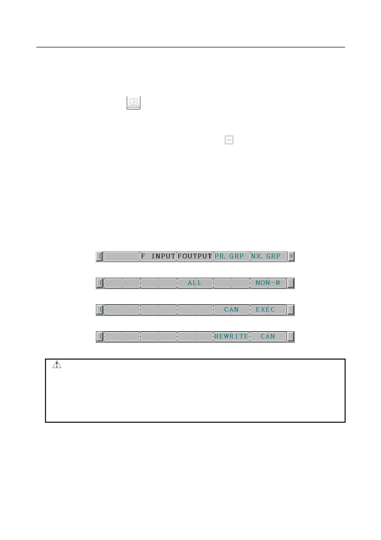
Press the soft key [F OUTPUT]. The soft key display switches from the one in Fig. 8.1 (b) to the one
in Fig. 8.1 (c).
7
If all parameters are to be output, press the soft key [ALL]. If only the parameters with nonzero
values are to be output, press the soft key [NON-0]. The soft key displays change from those
displayed in Fig. 8.1 (c) to those displayed in Fig. 8.1 (d).
8
Press the soft key [EXEC]. Because no file name is specified, the file is output with a file name of
CNC-PARA.TXT, but if a file with the same name exists on the memory card, the soft key display
switches from the one in Fig. 8.1 (d) to the one in Fig. 8.1 (e), with a confirmation message
appearing.
If a file with the same name does not exist on the memory card, the file is output directly.
9
Pressing the soft key [REWRITE] causes the file to be overwritten.
Pressing the soft key [CAN] causes output to be canceled. If wishing to output the file after changing
the file name, specify a file name after step 6, and perform step 7 again.
Fig. 8.1 (b) Soft key display before [F OUTPUT] is pressed
Fig. 8.1 (c) Soft key display after [F OUTPUT] is pressed
Fig. 8.1 (d) Soft key display after [ALL] or [NON-0] is pressed
Fig. 8.1 (e) Soft key display after [EXEC] is pressed
CAUTION
If a file to be overwritten has the read-only attribute, the warning message
"OVER WRITE FAILED" appears to cancel output even when the soft key
[REWRITE] is pressed for that file.
If a memory card is pulled out or inserted while a message for confirming
overwriting is displayed, it is likely that the write operation may fail and, at worst,
files on the memory card may be broken.
- 446 -

B-64304EN/02
OPERATION
8.DATA INPUT/OUTPUT
8.2
INPUT/OUTPUT ON EACH SCREEN
This section explains how to input and output data of the following types to and from each operation
screen: program, parameter, offset, pitch error compensation, macro variable, workpiece coordinate
system data, and operation history.
Section 8.2, "INPUT/OUTPUT ON EACH SCREEN", consists of the following subsections:
8.2.1 Inputting and Outputting a Program
447
8.2.1.1 Inputting a program
447
8.2.1.2 Outputting a program
448
8.2.2 Inputting and Outputting Parameters
449
8.2.2.1 Inputting parameters
449
8.2.2.2 Outputting parameters
449
8.2.3 Inputting and Outputting Offset Data
450
8.2.3.1 Inputting offset data
450
8.2.3.2 Outputting offset data
451
8.2.4 Inputting and Outputting Pitch Error Compensation Data
453
8.2.4.1 Inputting pitch error compensation data
453
8.2.4.2 Outputting pitch error compensation data
454
8.2.4.3 Input/output format of pitch error compensation data
454
8.2.5 Inputting and Outputting Custom Macro Common Variables
455
8.2.5.1 Inputting custom macro common variables
455
8.2.5.2 Outputting custom macro common variables
456
8.2.6 Inputting and Outputting Workpiece Coordinates System Data
457
8.2.6.1 Inputting workpiece coordinate system data
457
8.2.6.2 Outputting workpiece coordinate system data
457
8.2.7 Inputting and Outputting Operation History Data
458
8.2.7.1 Outputting operation history data
458
8.2.1
Inputting and Outputting a Program
8.2.1.1 Inputting a program
The following explains how to input a program from an external device to the memory of the CNC by
using the program editing screen or program folder screen.
Inputting a program
Procedure
1
Make sure the input device is ready for reading.
2
Press the function key
to display the program editing screen or program folder screen.
3
Press the EDIT switch on the machine operator’s panel or enter state emergency stop.
4
Press the soft key [(OPRT)].
5
Press the continuous menu key
until soft key [F INPUT] appears.
Press the soft key [F INPUT].
6
Type the name of the file that you want to input.
Press the soft key [F-NAME]. To specify the program number to input, type the program number
and press the soft key [O SET].
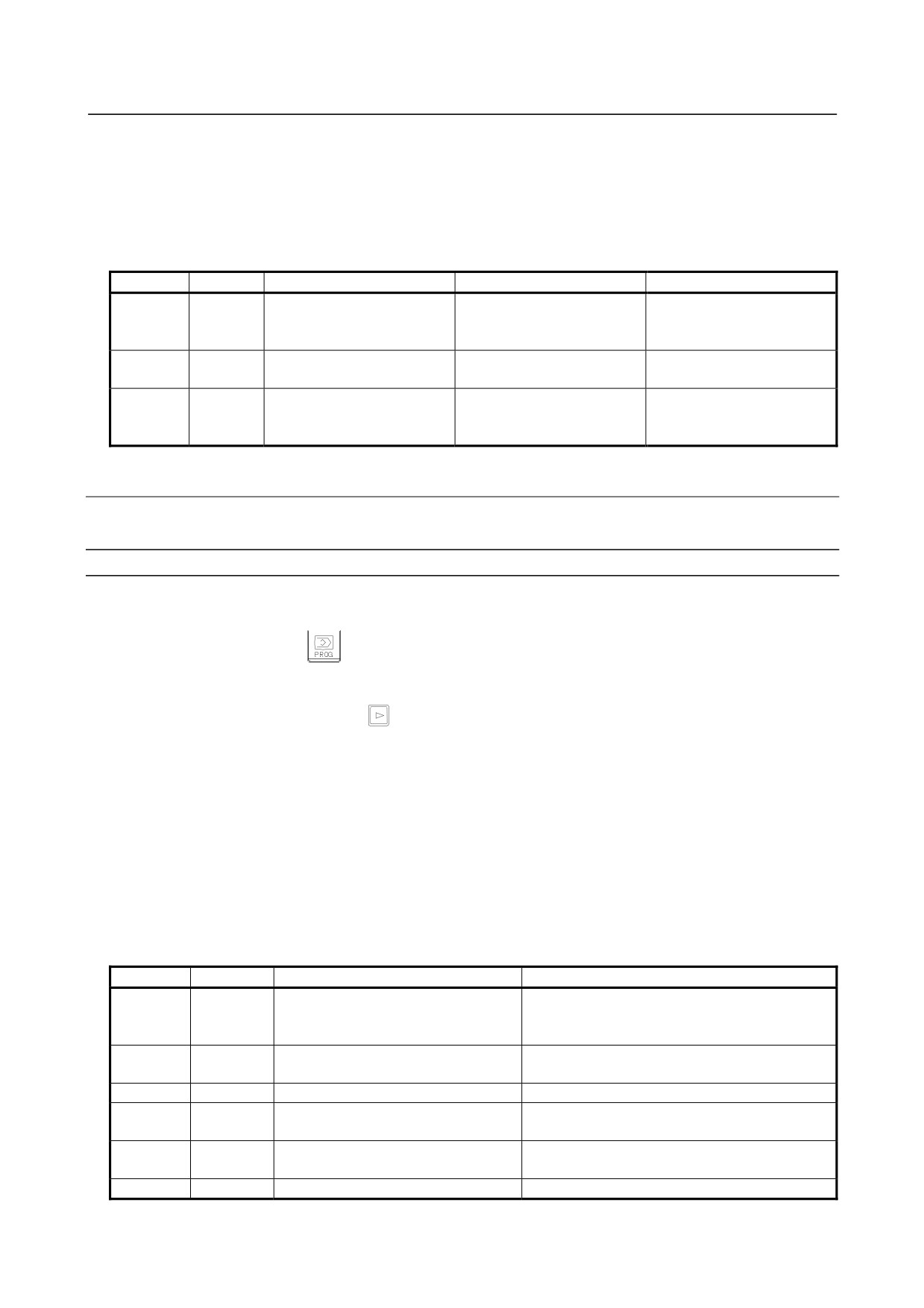
For an explanation of the operations to be performed if an input file name [F-NAME] and an input
program number [O SET] are omitted, see the table below.
- 447 -
8.DATA INPUT/OUTPUT
OPERATION
B-64304EN/02
7
Press the soft key [EXEC].
This starts reading the program, and “INPUT” blinks in the lower right part of the screen. When the
read operation ends, the “INPUT” indication disappears.
To cancel the input of the program, press the soft key [CAN].
The read program is registered in the program memory of the path currently selected.
[F-NAME]
[O SET]
Input file name
Input program
Input program number
Continuous program
File for the program number
All programs in the program
BLANK
INPUT
numbers starting at one
specified with [O SET]
specified with [O SET]
specified with [O SET]
File name set with
All programs in the file
File name at the time the file
INPUT
BLANK
[F-NAME]
specified with [F-NAME]
is saved
Continuous program
File name set with
All programs in the file
INPUT
INPUT
numbers starting at one
[F-NAME]
specified with [F-NAME]
specified with [O SET]
8.2.1.2 Outputting a program
A program stored in the memory of the CNC unit is output to an external device.
Outputting a program
Procedure
1
Make sure the output device is ready for writing.
2
Press the function key
to display the program editing screen or program folder screen.
3
Press the EDIT switch on the machine operator’s panel or enter state emergency stop.
4
Press the soft key [(OPRT)].
5
Press the continuous menu key
until soft key [F OUTPUT] appears.
Press the soft key [F OUTPUT].
6
Type the program number to output and press the soft key [O SET]. To specify an output file name,
type the output file name and press the soft key [F-NAME].
If no output file name or output program number is specified here, the main program or the program
being subjected to background editing is output.
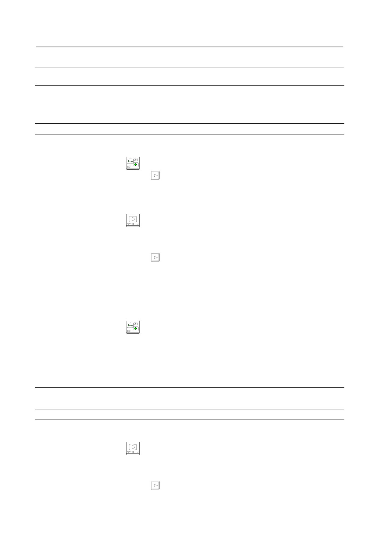
For an explanation of the operations to be performed if an output file name [F-NAME] and an output
program name [O SET] are omitted, see the table below.
7
Press the soft key [EXEC].
This starts outputting the program, and “OUTPUT” blinks in the lower right part of the screen.
When the write operation ends, the “OUTPUT” indication disappears.
To cancel the output, press the soft key [CAN].
[F-NAME]
[O SET]
Output file name
Output program
Main program or program number
Main program or program being subjected to
BLANK
BLANK
being subjected to background
background editing
editing
All programs in the program memory that are
BLANK
-9999
ALL-PROG.TXT
displayed in the program list
BLANK
INPUT
Program number set with [O SET]
Program in the NC that is set with [O SET]
Main program or program being subjected to
INPUT
BLANK
File name set with [F-NAME]
background editing
All programs in the program memory that are
INPUT
-9999
File name set with [F-NAME]
displayed in the program list
INPUT
INPUT
File name set with [F-NAME]
Program in the NC that is set with [O SET]
- 448 -
B-64304EN/02
OPERATION
8.DATA INPUT/OUTPUT
8.2.2
Inputting and Outputting Parameters
8.2.2.1 Inputting parameters
Parameters are loaded into the memory of the CNC unit from an external device. The input format is the
same as the output format. When a parameter is loaded which has the same data number as a parameter
already registered in the memory, the loaded parameter replaces the existing parameter.
Inputting parameters
Procedure
1
Make sure the input device is ready for reading.
2
Press the function key
3
Press the continuous menu key
until soft key [SETTING] appears.
Press the soft key [SETTING].
4
Press the MDI switch on the machine operator’s panel or enter state emergency stop.
5
Enter 1 in response to the prompt for “PARAMETER WRITE” in setting data.
Alarm SW0100 appears.
6
Press the function key
7
Press the soft key [PARAMETER], then the parameter screen appears.
8
Press the EDIT switch on the machine operator’s panel or enter state emergency stop.
9
Press the soft key [(OPRT)].
10
Press the continuous menu key
until soft key [F INPUT] appears.
Press the soft key [F INPUT].
11
Type the name of the file that you want to input.
If the input file name is omitted, default input file name “CNC-PARA.TXT” is assumed.
12
Press the soft key [EXEC].
This starts reading the parameter, and “INPUT” blinks in the lower right part of the screen. When
the read operation ends, the “INPUT” indication disappears.
To cancel the input of the program, press the soft key [CAN].
13
Press the function key
14
Press the soft key [SETTING].
15
Press the MDI switch on the machine operator’s panel or enter state emergency stop.
16
Enter 0 in response to the prompt for “PARAMETER WRITE” in setting data.
17
Turn the power of the CNC on again.
8.2.2.2 Outputting parameters
All parameters are output in a defined output format from the memory of the CNC to an external device.
Outputting parameters
Procedure
1
Make sure the output device is ready for writing.
2
Press the function key
3
Press the soft key [PARAMETER], then the parameter screen appears.
4
Press the EDIT switch on the machine operator’s panel or enter state emergency stop.
5
Press the soft key [(OPRT)].
6
Press the continuous menu key
until soft key [F OUTPUT] appears.
Press the soft key [F OUTPUT].
- 449 -
8.DATA INPUT/OUTPUT
OPERATION
B-64304EN/02
7
If all parameters are to be output, press the soft key [ALL]. If only the parameters with nonzero
values are to be output, press the soft key [NON-0].
8
Type the file name that you want to output.
If the file name is omitted, default file name “CNC-PARA.TXT” is assumed.
9
Press the soft key [EXEC].
This starts outputting the parameter, and “OUTPUT” blinks in the lower right part of the screen.
When the write operation ends, the “OUTPUT” indication disappears.
To cancel the output, press the soft key [CAN].
Explanation
-
Suppressing output of parameters set to 0
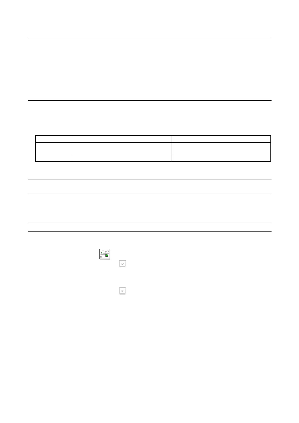
When bit 1 (PRM) of parameter No. 0010 is set to 1, and soft key [EXEC] is pressed, the following
parameters are not output:
Other than axis type
Axis type
Parameter for an axis for which all bits are set to
Bit type
Parameter for which all bits are set to 0.
0.
Value type
Parameter whose value is 0.
Parameter for an axis for which the value is 0.
8.2.3
Inputting and Outputting Offset Data
8.2.3.1 Inputting offset data
Offset data is loaded into the memory of the CNC from an external device. The input format is the same
as for offset value output. When an offset value is loaded which has the same offset number as an offset
number already registered in the memory, the loaded offset data replaces existing data.
Inputting offset data
Procedure
1
Make sure the input device is ready for reading.
2
Press the function key
3
Press the continuous menu key
until soft key [OFFSET] appears.
Press the soft key [OFFSET].
4
Press the EDIT switch on the machine operator’s panel or enter state emergency stop.
5
Press the soft key [(OPRT)].
6
Press the continuous menu key
until soft key [F INPUT] appears.
Press the soft key [F INPUT].
7
Type the name of the file that you want to input.
If the input file name is omitted, default input file name “TOOLOFST.TXT” is assumed.
8
Press the soft key [EXEC].
This starts reading the offset data, and “INPUT” blinks in the lower right part of the screen. When
the read operation ends, the “INPUT” indication disappears.
To cancel the input of the program, press the soft key [CAN].
- 450 -
B-64304EN/02
OPERATION
8.DATA INPUT/OUTPUT
8.2.3.2 Outputting offset data
All offset data is output in a defined output format from the memory of the CNC to an external device.
Outputting offset data
Procedure
1
Make sure the output device is ready for writing.
2
Press the function key
3
Press the continuous menu key
until soft key [OFFSET] appears.
Press the soft key [OFFSET].
4
Press the EDIT switch on the machine operator’s panel or enter state emergency stop.
5
Press the soft key [(OPRT)].
6
Press the continuous menu key
until soft key [F OUTPUT] appears.
Press the soft key [F OUTPUT].
7
Type the file name that you want to output.
If the file name is omitted, default file name “TOOLOFST.TXT” is assumed.
8
Press the soft key [EXEC].
This starts outputting the offset data, and “OUTPUT” blinks in the lower right part of the screen.
When the write operation ends, the “OUTPUT” indication disappears.
To cancel the output, press the soft key [CAN].
Explanation
-
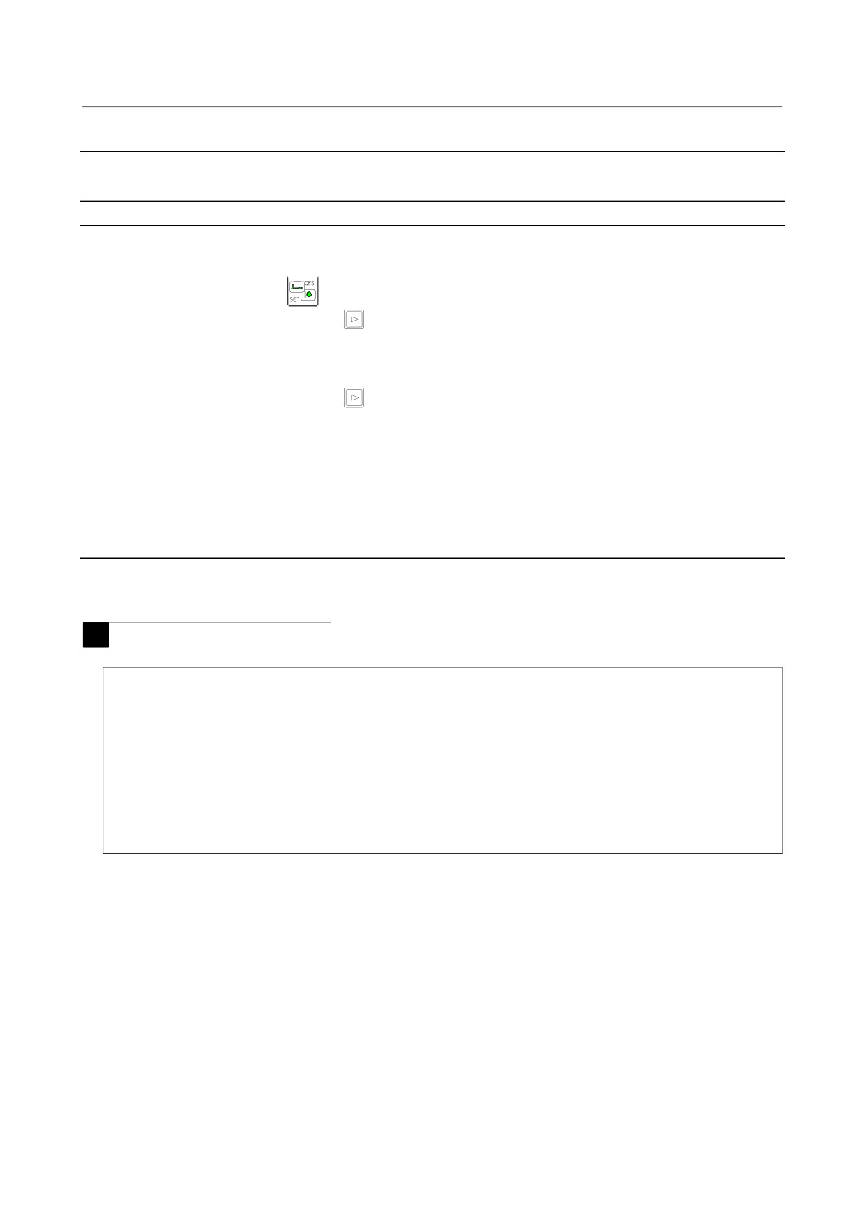
Output format
Output format is as follows:
M
• Tool compensation memory A (bit 6 (NGW) of parameter No.8136 = 1)
%
G10 G90 P01 R_
G10 G90 P02 R_
G10 G90 P_ R_
%
P_ : Tool offset number (1 to the number of tool compensation pairs)
R_ : Tool compensation data. Output with a decimal point in the input unit used at output.
- 451 -
8.DATA INPUT/OUTPUT
OPERATION
B-64304EN/02
• Tool compensation memory C (bit 6 (NGW) of parameter No.8136 = 0)
%
G10 G90 L10 P01 R_
G10 G90 L11 P01 R_
G10 G90 L12 P01 R_
G10 G90 L13 P01 R_
G10 G90 L10 P02 R_
G10 G90 L12 P_ R_
G10 G90 L13 P_ R_
%
L10 : Geometry compensation amount corresponding to the H code
L11 : Wear compensation amount corresponding to the H code
L12 : Geometry compensation amount corresponding to the D code
L13 : Wear compensation amount corresponding to the D code
P_, and R_ have the same meanings as for tool compensation memory A.
T
• Without geometry/wear offset (bit 6 (NGW) of parameter No.8136 = 1)
The tool compensation amount and tool nose radius compensation amount
are
output
in
the
following format.
%
G10 P01 X_ Z_ R_ Q_ Y_
G10 P02 X_ Z_ R_ Q_ Y_
G10 P__ X_ Z_ R_ Q_ Y_
%
P_: Tool compensation number (1 to the number of tool compensation pairs)
Tool offset number: Tool compensation amount
X_: Tool compensation data (X). Output with a decimal point in the input unit used at
output.
Z_: Tool compensation data (Z). Same as X_.
R_: Tool nose radius offset amount (R). The data format is the same as for X_.
When tool nose radius compensation is not provided, this item is not output.
Q_: Virtual tool nose number (TIP). When tool nose radius compensation is not provided,
this item is not output.
Y_ : Tool compensation data (Y). The data format is the same as for X_.
When no Y-axis offset is provided, this item is not output.
• With geometry/wear offset (bit 6 (NGW) of parameter No.8136 = 0)
The tool compensation amount and tool nose radius compensation amount are output in the
following format.
- 452 -
B-64304EN/02
OPERATION
8.DATA INPUT/OUTPUT
%
G10 P01 X_ Z_ R_ Q_ Y_
G10 P02 X_ Z_ R_ Q_ Y_
G10 P__ X_ Z_ R_ Q_ Y_
G10 P10001 X_ Z_ R_ Y_
G10 P10002 X_ Z_ R_ Y_
G10 P100__ X_ Z_ R_ Y_
%
P_: Tool compensation number (1 to the number of tool compensation pairs)
Tool offset number: Tool wear compensation amount
10000 + tool offset number: Tool geometry compensation amount
X_: Tool compensation data (X). Output with a decimal point in the input unit used at
output.
Z_: Tool compensation data (Z). Same as X_.
R_: Tool nose radius offset amount (R). The data format is the same as for X_.
When tool nose radius compensation is not provided, this item is not output.
Q_: Virtual tool nose number (TIP). When tool nose radius compensation is not provided,
this item is not output.
Y_ : Tool compensation data (Y). The data format is the same as for X_.
When no Y-axis offset is provided, this item is not output.
NOTE
The input format and output format do not depend on the G-code system A/B/C.
8.2.4
Inputting and Outputting Pitch Error Compensation Data
8.2.4.1 Inputting pitch error compensation data
Pitch error compensation data are loaded into the memory of the CNC from an external device. The
input format is the same as the output format. When a pitch error compensation data is loaded which has
the corresponding data number as a pitch error compensation data already registered in the memory, the
loaded data replaces the existing data.
Inputting pitch error compensation data
Procedure
1
Make sure the input device is ready for reading.
2
Press the function key
3
Press the continuous menu key
until soft key [SETTING] appears.
Press the soft key [SETTING].
4
Press the MDI switch on the machine operator’s panel or enter state emergency stop.
5
Enter 1 in response to the prompt for “PARAMETER WRITE” in setting data.
Alarm SW0100 appears.
6
Press the function key
7
Press the continuous menu key
until soft key [PITCH ERROR] appears.
Press the soft key [PITCH ERROR].
- 453 -
8.DATA INPUT/OUTPUT
OPERATION
B-64304EN/02
8
Press the EDIT switch on the machine operator’s panel or enter state emergency stop.
9
Press the soft key [(OPRT)].
10
Press the continuous menu key
until soft key [F INPUT] appears.
Press the soft key [F INPUT].
11 Type the name of the file that you want to input.
If the input file name is omitted, default input file name “PITCH.TXT” is assumed.
12 Press the soft key [EXEC].
This starts reading the pitch error compensation data, and “INPUT” blinks in the lower right part of
the screen. When the read operation ends, the “INPUT” indication disappears.
To cancel the input of the program, press the soft key [CAN].
13 Press the function key
14 Press the soft key [SETTING].
15 Press the MDI switch on the machine operator’s panel or enter state emergency stop.
16 Enter 0 in response to the prompt for “PARAMETER WRITE” in setting data.
17 Turn the power of the CNC on again.
8.2.4.2 Outputting pitch error compensation data
All pitch error compensation data are output in a defined output format from the memory of the CNC to
an external device.
Outputting pitch error compensation data
Procedure
1
Make sure the output device is ready for writing.
2
Press the function key
3
Press the continuous menu key
until soft key [PITCH ERROR] appears.
Press the soft key [PITCH ERROR].
4
Press the EDIT switch on the machine operator’s panel or enter state emergency stop.
5
Press the soft key [(OPRT)].
6
Press the continuous menu key
until soft key [F OUTPUT] appears.
Press the soft key [F OUTPUT].
7
Type the file name that you want to output.
If the file name is omitted, default file name “PITCH.TXT” is assumed.
8
Press the soft key [EXEC].
This starts outputting the pitch error compensation data, and “OUTPUT” blinks in the lower right
part of the screen. When the write operation ends, the “OUTPUT” indication disappears.
To cancel the output, press the soft key [CAN].
8.2.4.3 Input/output format of pitch error compensation data
Pitch error compensation data is input and output in the following input and output formats.
-
Keywords
The following alphabets are used as keywords.
The numeric value following each keyword has the meaning listed below:
Keyword
Meaning of the following numeric value
N
Pitch error compensation data number + 10000
Q
Data identification
(1 : Parameter data, 0 : Pitch error compensation data )
P
Pitch error compensation data value
- 454 -
B-64304EN/02
OPERATION
8.DATA INPUT/OUTPUT
-
Format
Pitch error compensation data is output in the following format:
N
*****
Q0
P
****
;
The 5-digit numeric value following N indicates a pitch error compensation data number to which a
value of 10000 is added.
Q0 indicates pitch error compensation data
The numeric value following P indicates the value (integer value) of pitch error compensation data
between -7 to 7.
The semicolon (;) indicates the end of block (LF in the ISO code or CR in the EIA code).
Example
N10001 Q0 P100 ;
Pitch error compensation data number
1
Pitch error compensation data value
100
-
Beginning and end of a record
A pitch error compensation data record begins with % and ends with %.
Example
%
Beginning of record
N10000 Q0 P10
N10001 Q0 P100
:
N11023 Q0 P0
%
End of record
When parameters and pitch error compensation data are integrated into one file, % is added to the
beginning and end of the file.
8.2.5
Inputting and Outputting Custom Macro Common Variables
8.2.5.1 Inputting custom macro common variables
The value of a custom macro common variable is loaded into the memory of the CNC from an external
device. The same format used to output custom macro common variables is used for input.
Inputting custom macro common variables
Procedure
1
Make sure the input device is ready for reading.
2
Press the function key
3
Press the continuous menu key
until soft key [MACRO] appears.
Press the soft key [MACRO].
4
Press the EDIT switch on the machine operator’s panel or enter state emergency stop.
5
Press the soft key [(OPRT)].
6
Press the continuous menu key
until soft key [F INPUT] appears.
Press the soft key [F INPUT].
- 455 -