FANUC Series 16i/160i/160is-MB, Series 18i/180i/180is-MB5, Series 18i/180i/180is-MB. Operator's Manual - page 24
22. RISC PROCESSOR
PROGRAMMING
B-63534EN/02
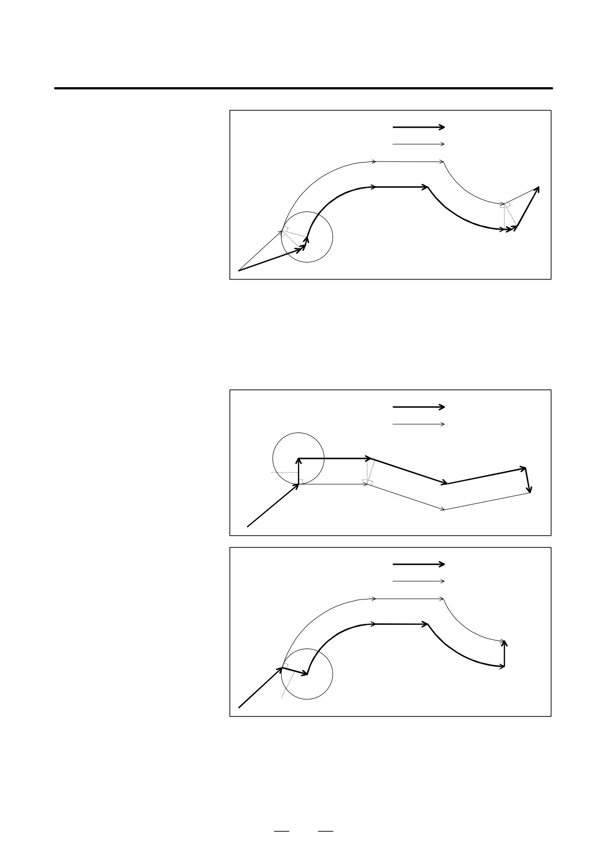
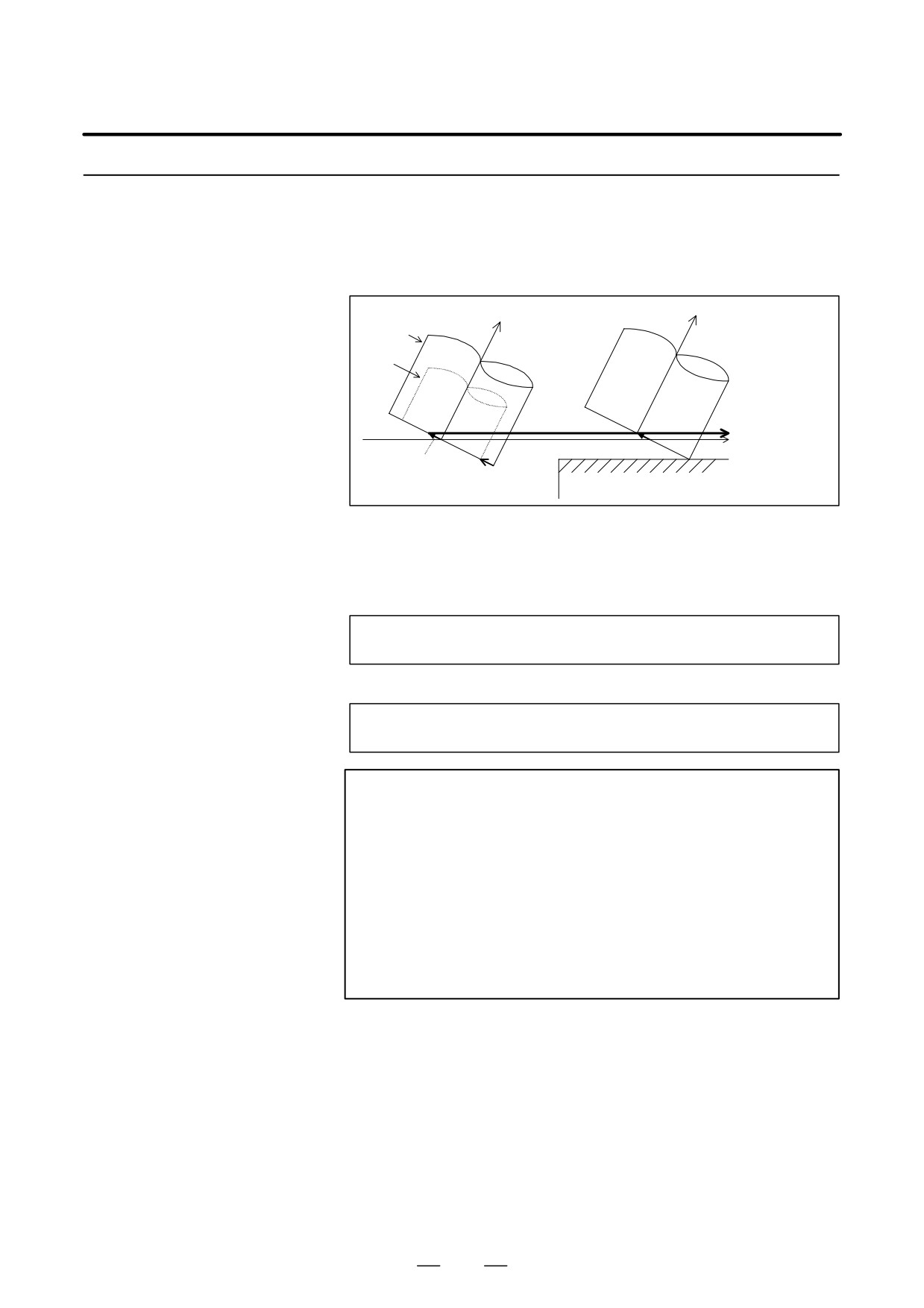
Operation in circular interpolation
:Tool center path
:Programmed tool path
G40
G42.2
Tool
Fig. 22.5.1 (c) Operation at compensation start-up and cancellation
(Type B)
(3) Type C
As shown in the following figures, when G41.2, G42.2, or G40 is
specified, a block is inserted which moves the tool perpendicularly
to the movement direction specified in the next block by the distance
of the tool radius.
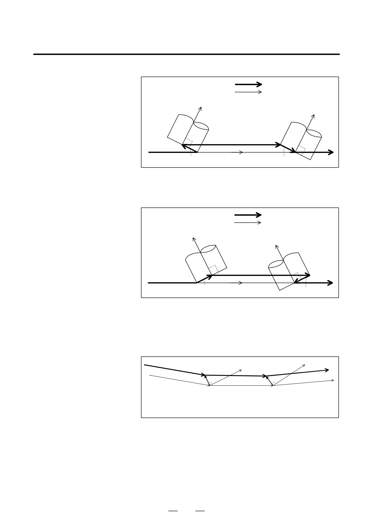
Operation in linear interpolation
:Tool center path
:Programmed tool path
Tool
G41.2
G40
Operation in circular interpolation
:Tool center path
:Programmed tool path
G40
Tool
G42.2
Fig. 22.5.1 (d) Operation at compensation start-up and cancellation
(Type C)
670
B-63534EN/02
PROGRAMMING
22. RISC PROCESSOR
NOTE
For type C operation, the following conditions must be satisfied
when tool side compensation is started up or canceled :
1
The block containing G40, G41.2, or G42.2 must be
executed in the G00 or G01 mode.
2
The block containing G40, G41.2, or G42.2 must have no
move command.
3
The block after the block containing G41.2 or G42.2 must
contain a G00, G01, G02, or G03 move command.
D Operation in the
Changing of offset directions and offset values, holding of vectors,
compensation mode
interference checks, and so on are performed in the same way as for cutter
compensation. G39 (corner rounding) cannot be specified. So, note the
following :
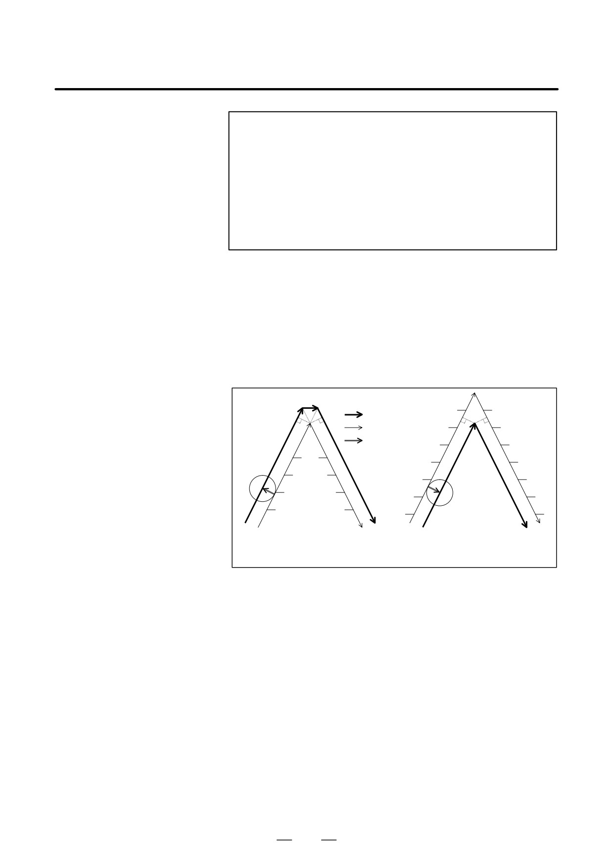
(1) When the tool center path goes outside the programmed tool path at
a corner, a linear movement block, instead of an arc movement block,
is inserted to move the tool around the corner. When the tool center
path goes inside the programmed tool path, no block is inserted.
A linear movement block is inserted
No block is inserted
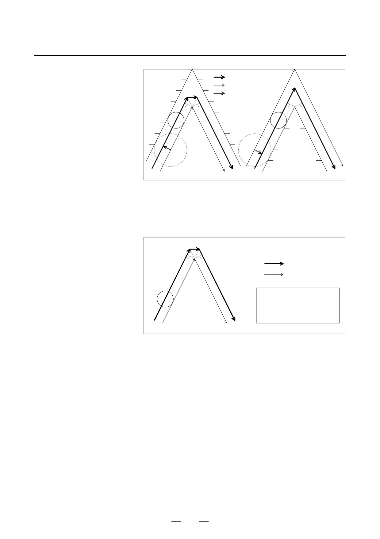
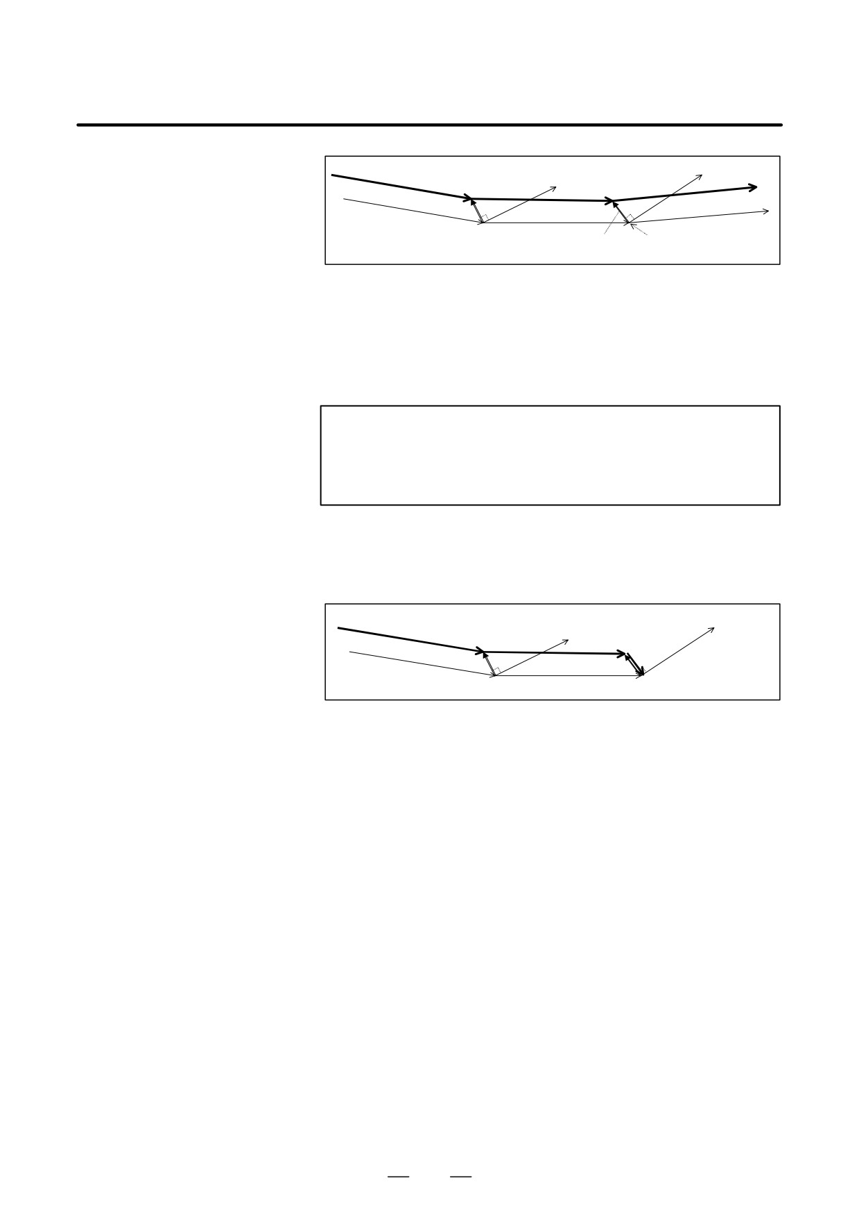
:Tool center path
:Programmed tool path
:Tool offset value
Workpiece
Tool
Workpiece
Tool
Example (1)-1 When going around the out-
Example (1)-2 When going around the in-
side of a corner with an
side of a corner with an
acute angle
acute angle
Fig. 22.5.1 (e) Operation in the compensation mode (1)-1, 2
In the above examples, the term “inside” means that the tool center
path is positioned inside the programmed tool path at a corner, and
“outside” means that the tool center path is positioned outside the
programmed tool path. In Example (1)-3, the relationship between
the tool center path and the programmed tool path is the same as in
Example (1)-1; the tool center path is positioned outside the
programmed tool path. Example (1)-4 has the same relationship as
Example (1)-2, where the tool center path is positioned inside the
programmed tool path.
671
22. RISC PROCESSOR
PROGRAMMING
B-63534EN/02
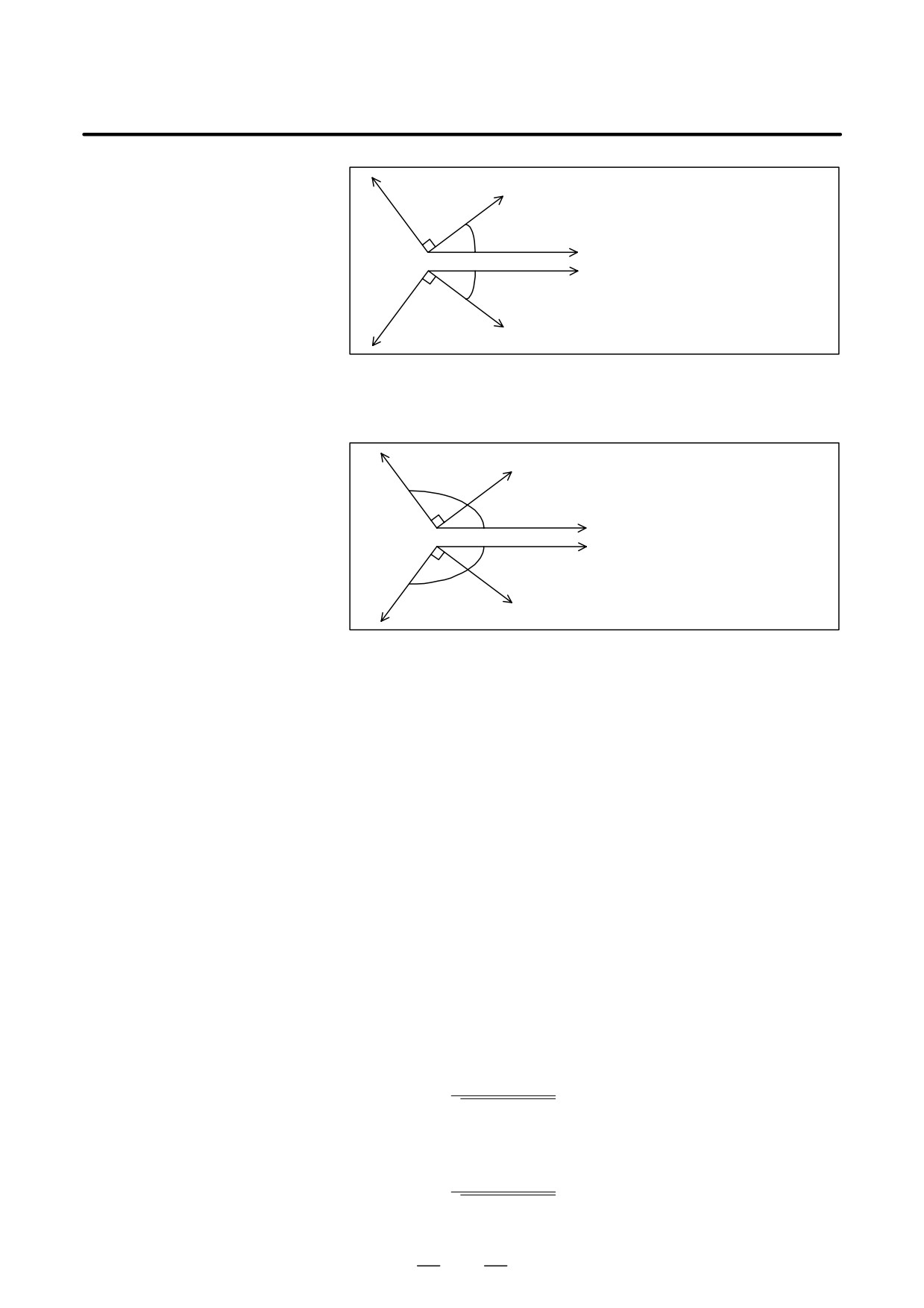
:Tool center path
Workpiece
:Programmed tool path
:Tool offset value
Actual tool
Actual tool
Reference tool
Workpiece
Reference tool
Example(1)-3
Example(1)-4
Fig. 22.5.1 (f) Operation in the compensation mode (1)-3, 4
(2) When the tool moves at a corner, the feedrate of the previous block
is used if the corner is positioned before a single-block stop point; if
the corner is after a single-block stop point, the feedrate of the next
block is used.
F100
Q1’
Q2’(Single block stop point)
:Tool center path
Q
:Programmed tool path
Tool
Program(2)-1
N2
N3
:
N1 G90G41.2 Xp Yp Zp Bp Cp D1 ;
N2 G01Xq Yq Zq F100 ;
N3 Xr Yr Zr F200 ;
:
P’
R’
P
R
Example(2)-1
Fig. 22.5.1 (g) Operation in the compensation mode (2)
In the above example, the single block stop point of N2 is Q2’, so that
the feedrates along paths P’-Q1’ and Q1’-Q2’ are the same, namely,
F100.
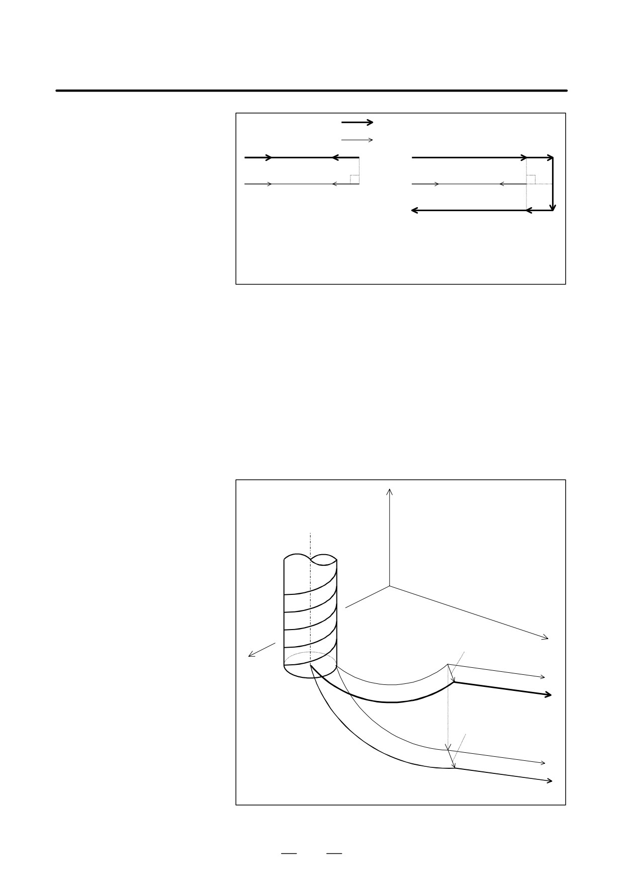
(3) When a command is specified to make the tool retrace the path
specified in the previous block, the tool path can match the locus of
the previous block by changing the G code to change the offset
direction. If the G code is left unchanged, the operation shown in
Example (3)-2 results :
672
B-63534EN/02
PROGRAMMING
22. RISC PROCESSOR
:Tool center path
:Programmed tool path
Example(3)-1
Tool movement when
Example(3)-2
Tool movement when the
changing G41.2 to G42.2
G code is left unchanged
(G41.2 mode)
(G41.2 mode)
G91 G01 X100.0
G91 G01 X100.0
G42.2 X-100.0
X-100.0
Fig. 22.5.1 (h) Operation in the compensation mode (3)
(4) Even when the tool movement changes linear to circular (helical),
circular (helical) to linear, or circular (helical) to circular (helical), the
start, end, and center points of a circular (helical) movement are
projected on the compensation plane that is perpendicular to the tool
axis, a compensation vector is calculated for the plane, then the vector
is added to the originally specified position to obtain the command
position. Then the tool is moved linearly or circularly (helically) to
the obtained command position. In this case, the tool moves
circularly (helically) in the currently selected plane. The tool does not
move circularly (helically) in the compensation plane. Therefore,
when the tool compensation is for circular movement, the
compensation plane must be the XY, YZ, or ZX plane.
Z
Tool axis
Tool
Y
Actual offset vector
End point
Start point
X
Move command
Actual tool center path
Projected
Offset vector created in
the compensation plane
Tool center path created in the
compensation plane
(Compensation plane = XY plane)
Fig. 22.5.1 (i) Operation in the compensation mode (4)
673
22. RISC PROCESSOR
PROGRAMMING
B-63534EN/02
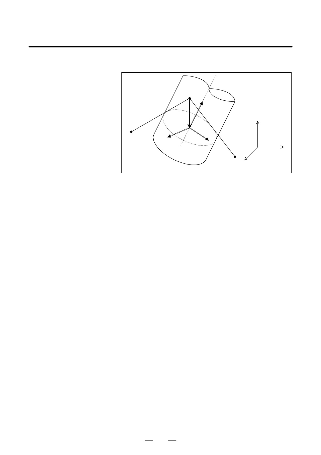
D Compensation vector
calculation
Q
e1=VT
VD
Z
P
e2
e3
Y
X
R
Fig. 22.5.1 (j) Compensation vector calculation
In above figure, cutter compensation vector VD at point Q is calculated
as follows :
(1) Calculating the tool vector (VT)
(2) Calculating the coordinate conversion matrix (M)
Coordinate systems are defined as follows :
- Coordinate system C1 :
{O; X, Y, Z}
Cartesian coordinate system whose fundamental vectors are the
following unit vectors along the X-, Y-, and Z-axes :
(1, 0, 0)
(0, 1, 0)
(0, 0, 1)
- Coordinate system C2 :
{O; e2, e3, e1}
Cartesian coordinate system whose fundamental vectors are the
following unit vectors :
e2
e3
e1
where, e2, e3, and e1 are defined as follows :
e1 = VT
e2 = b2 / |b2| , b2 = a2 - (a2,e1)- e1
e3 = b3 / |b3| , b3 = a3 - (a3,e1)- e1 - (a3,e2)- e2
a2 is an arbitrary vector linearly independent of e1, and
a3 is an arbitrary vector linearly indepen dent of e2 and e1.
The coordinate conversion matrix M from coordinate system C1 to
C2, and the coordinate conversion matrix M-1 from coordinate system
C2 to C1 are expressed as :
e2
M+ƪe3ƫ
,
M-1 + (te2
t e3
t e1)
e1
674
B-63534EN/02
PROGRAMMING
22. RISC PROCESSOR
(3) Converting coordinates from coordinate system C1 to coordinate
system C2
The coordinates of the start and end points P and Q of a block and
coordinates of the end point R of the next block in coordinate system
C1 are converted to coordinates P’, Q’, and R’ in coordinate system
C2, respectively, by using the following expressions :
PȀ + MP
QȀ + QP
RȀ + MR
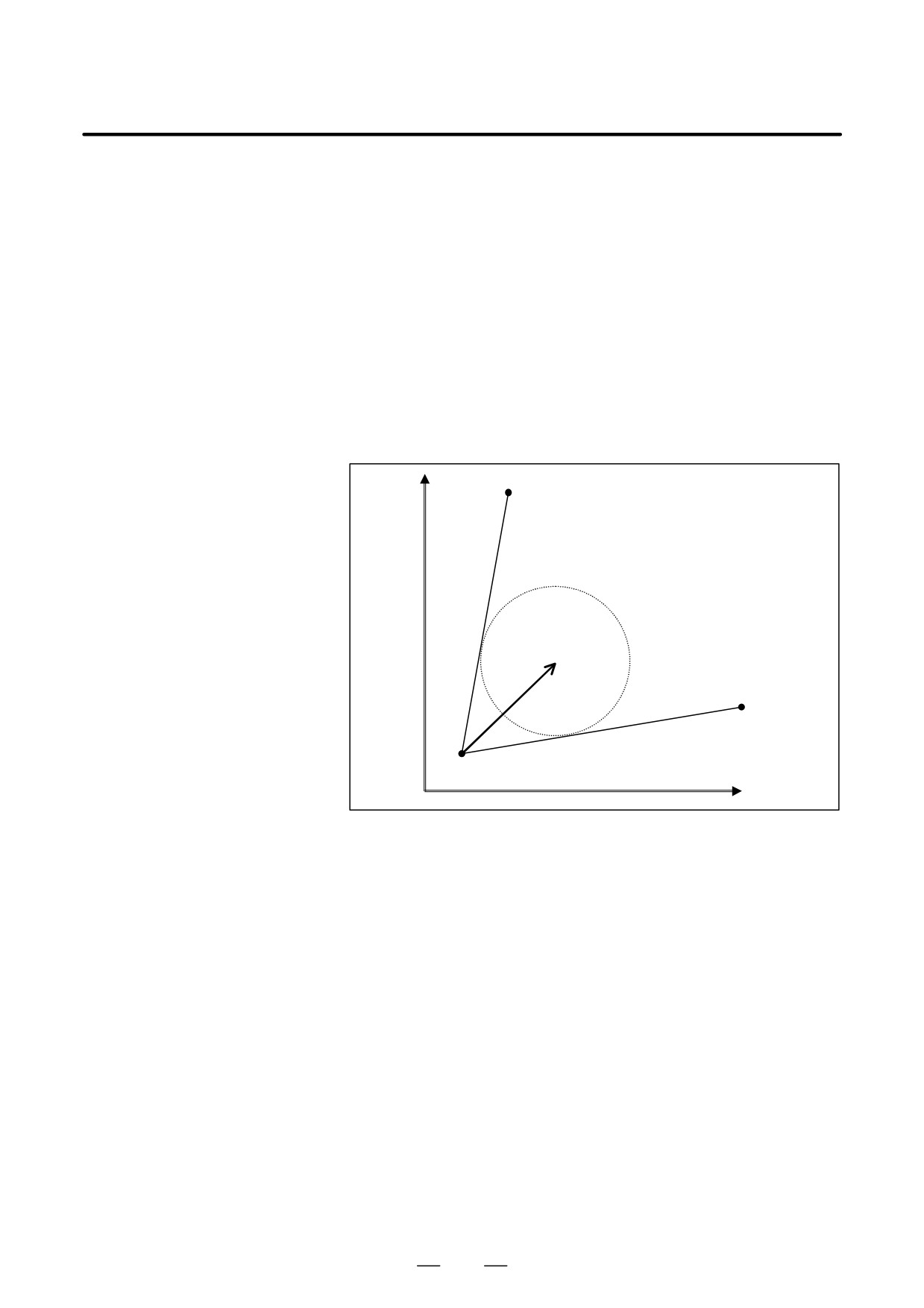
(4) Calculating the intersection vector (VD’) in the compensation plane
{O; e2, e3}
In the coordinates in coordinate system C2 obtained in (3), two
components (the e1 component, the component of the tool direction,
is excluded) are used to calculate intersection vector VD’ in the
compensation plane.
e3
R’
VD’
P’
Q’
e2
Fig. 22.5.1 (k) Compensation vector calculation
The e1 component of VD’ is assumed to be always 0. The calculation
is similar to the calculation of cutter compensation C. Although one
vector is obtained in this example, up to four vectors may be
calculated.
If the difference between the e2 and e3 components
(in the
compensation plane) between two points is smaller than the value set
in parameter No. 6114 in intersection vector calculation, the block is
assumed to specify no movement. In this case, intersection calculation
is performed using the coordinates of one block ahead.
(5) Converting the intersection vector from coordinate system C2 to
coordinate system C1
From the following expression, vector VD’ in coordinate system C2
is converted to vector VD in coordinate system C1 :
VD + M-1VDȀ
Vector VD is the compensation vector in the original XYZ coordinate
system.
675
22. RISC PROCESSOR
PROGRAMMING
B-63534EN/02
D Calculation used when
the compensation plane
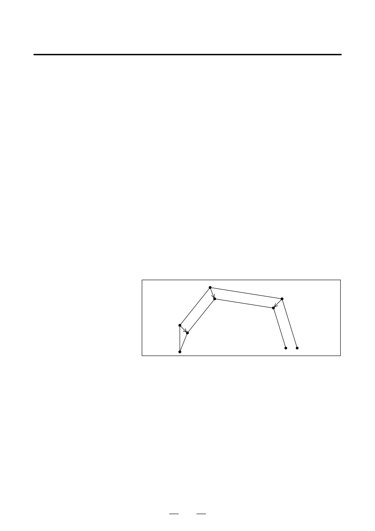
(1) When a rotation axis and linear axis are specified at the same time
is changed
When a rotation axis and linear axis are specified in the same block
in the G41.2 or G42.2 mode (the compensation plane changes
frequently), the cutter compensation vector is calculated using the
coordinates of the rotation axis at each point at which the vector is
obtained.
<Example>
G90 G00 X0 Y0 Z0 B0 C0 ;
G01 F1000 ;
N1 G42.2 Xp Yp Zp Bp Cp D1 ;
N2 Xq Yq Zq Bq Cq ;
N3 Xr Yr Zr Br Cr ;
N4 Xs Ys Zs Bs Cs ;
:
Vector calculation at the end point (Q) of block N2
- The tool vector (VT) and coordinate conversion matrix (M) are
calculated using the coordi nates (Bq, Cq) of the rotation axis at point
Q.
- The cutter compensation vector is calculated using the resultant
coordinates into which three points, P, Q, and R, are converted by
matrix M.
Q
N3
R
N2
Q’
R’
N4
P
N1
P’
O
S’
S
Fig. 22.5.1 (l) When a Rotation Axis and Linear Axis Are Specified at the
Same Time
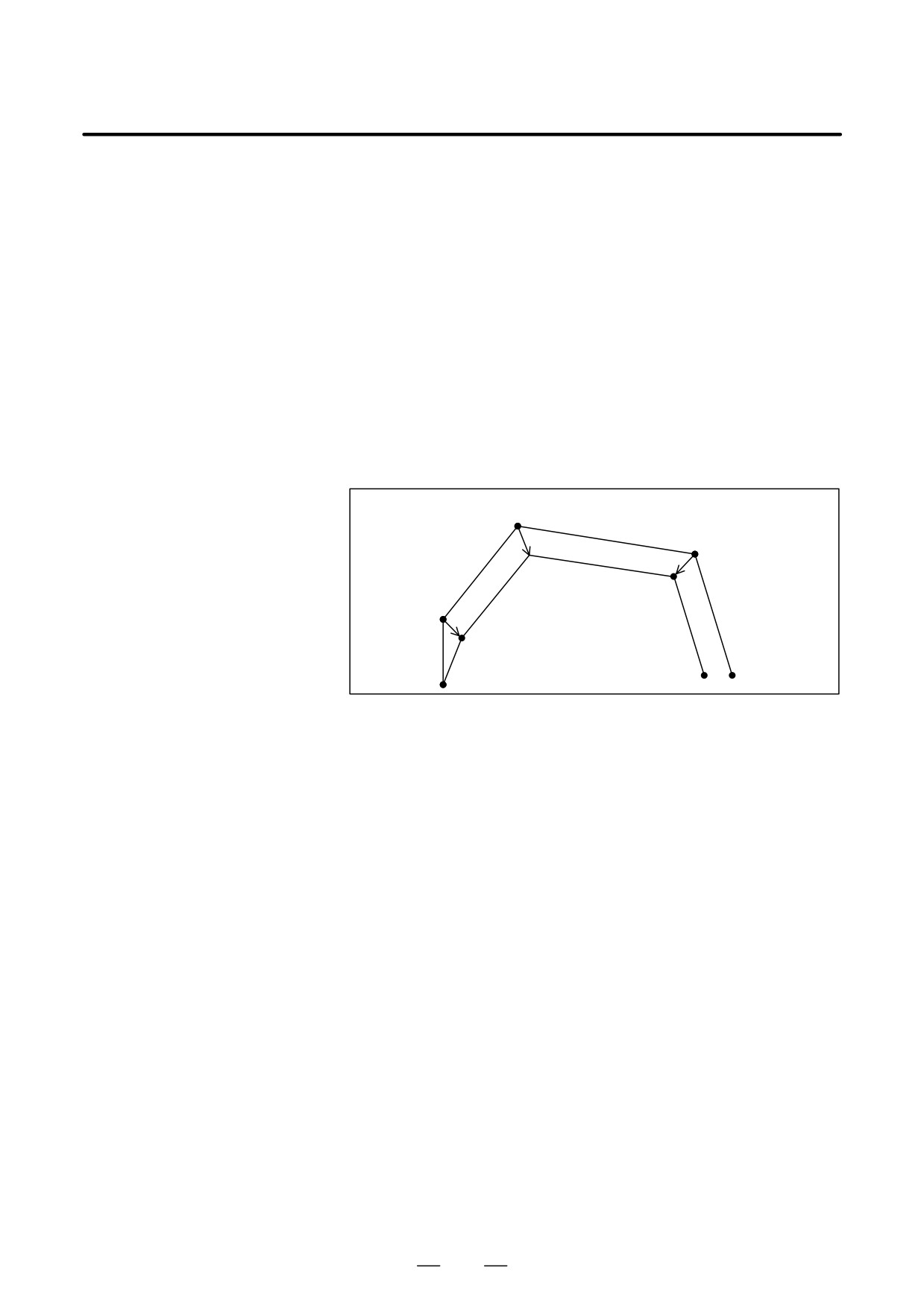
(2) When a rotation axis is specified alone
When a rotation axis is specified alone in the G41.2 or G42.2 mode
(the compensation plane changes), the cutter compensation vector is
calculated as follows :
<Example>
G90 G00 X0 Y0 Z0 B0 C0 ;
G01 F1000 ;
N1 G42.2 Xp Yp Zp D1 ;
N2 Xq Yq Zq ;
N3 Br Cr ;
N4 Xs Ys Zs ;
:
676
B-63534EN/02
PROGRAMMING
22. RISC PROCESSOR
Vector calculation at the end point (Q) of block N2
- The tool vector (VT) and coordinate conversion matrix (MN2) are
calculated using the coordinates (B = 0, C = 0) of the rotation axis at
point Q.
- The cutter compensation vector (VN2) is calculated using the resultant
coordinates into which three points, P, Q, and S, are converted by
matrix MN2.
Vector calculation at the end point of block N3
- The coordinate conversion matrix (MN3) is calculated using the
coordinates (Br, Cr) of the rotation axis at point R.
- The cutter compensation vector (VN3) is calculated from the following
expression :
VN3 = MN3-1(MN2-VN2)
Q=R(N3)
N4
S
VN2=V3
N2
Q’=R’
S’
P
N1
P’
O
Fig. 22.5.1 (m) When a rotation axis is specified alone
D Interference check made
An interference check is made when the compensation plane (plane
when the compensation
perpendicular to a tool direction vector) is changed.
plane is changed
<Example>
If the program below is executed, a PS0272 alarm (overcutting due to
offsetting) is issued from N4.
O100 F3000
N1 G90 G00 X0 Y0 Z0 A-46 C180
N2 G41.2 D1
N3 G01 X100
N4 Y-200 Z-200
N5 A45
N6 Y-400 Z0
N7 X0
N8 Y-200 Z-200
N9 A-46
N10 Y0 Z0
N11 G40
M30
677
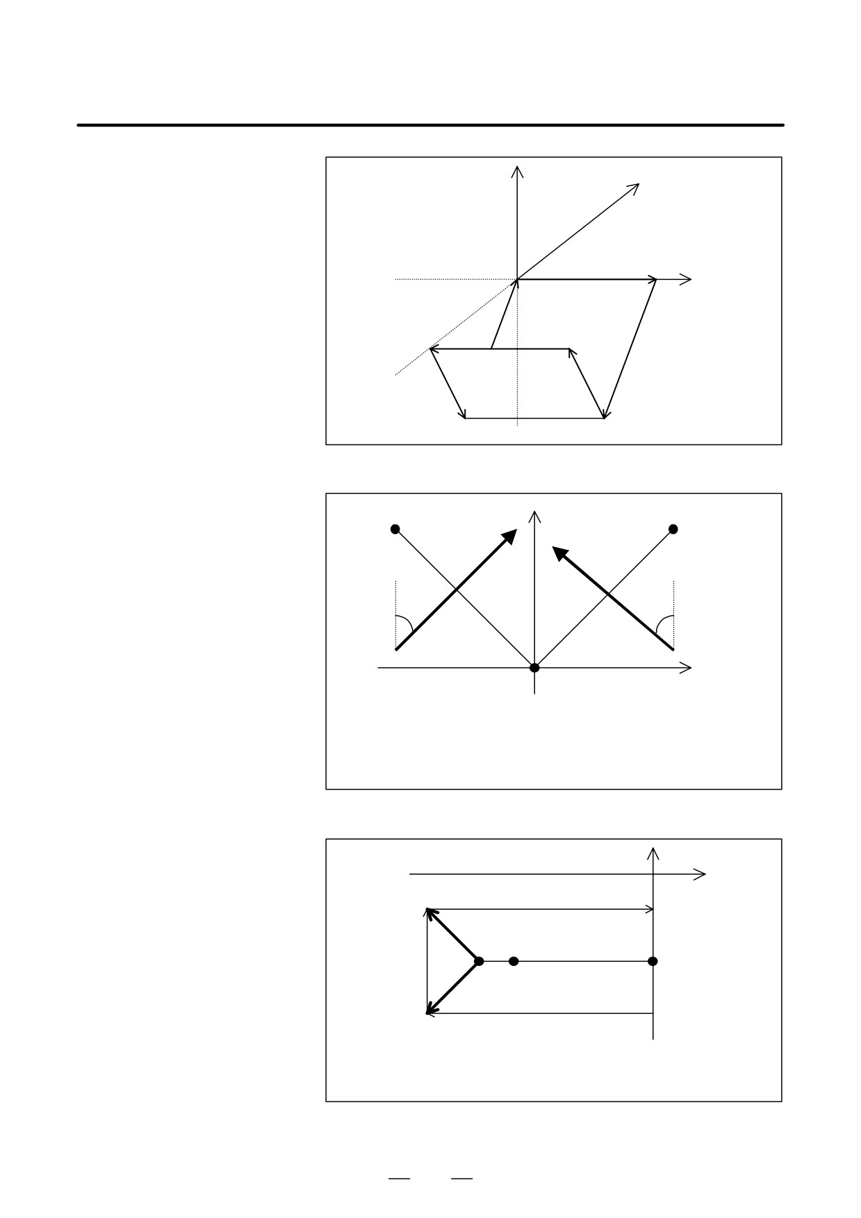
22. RISC PROCESSOR
PROGRAMMING
B-63534EN/02
Z
Y
N3
X
N10
N7
N4
N6
N8
N9
N5
Fig. 22.5.1 (n) Conceptual Diagram
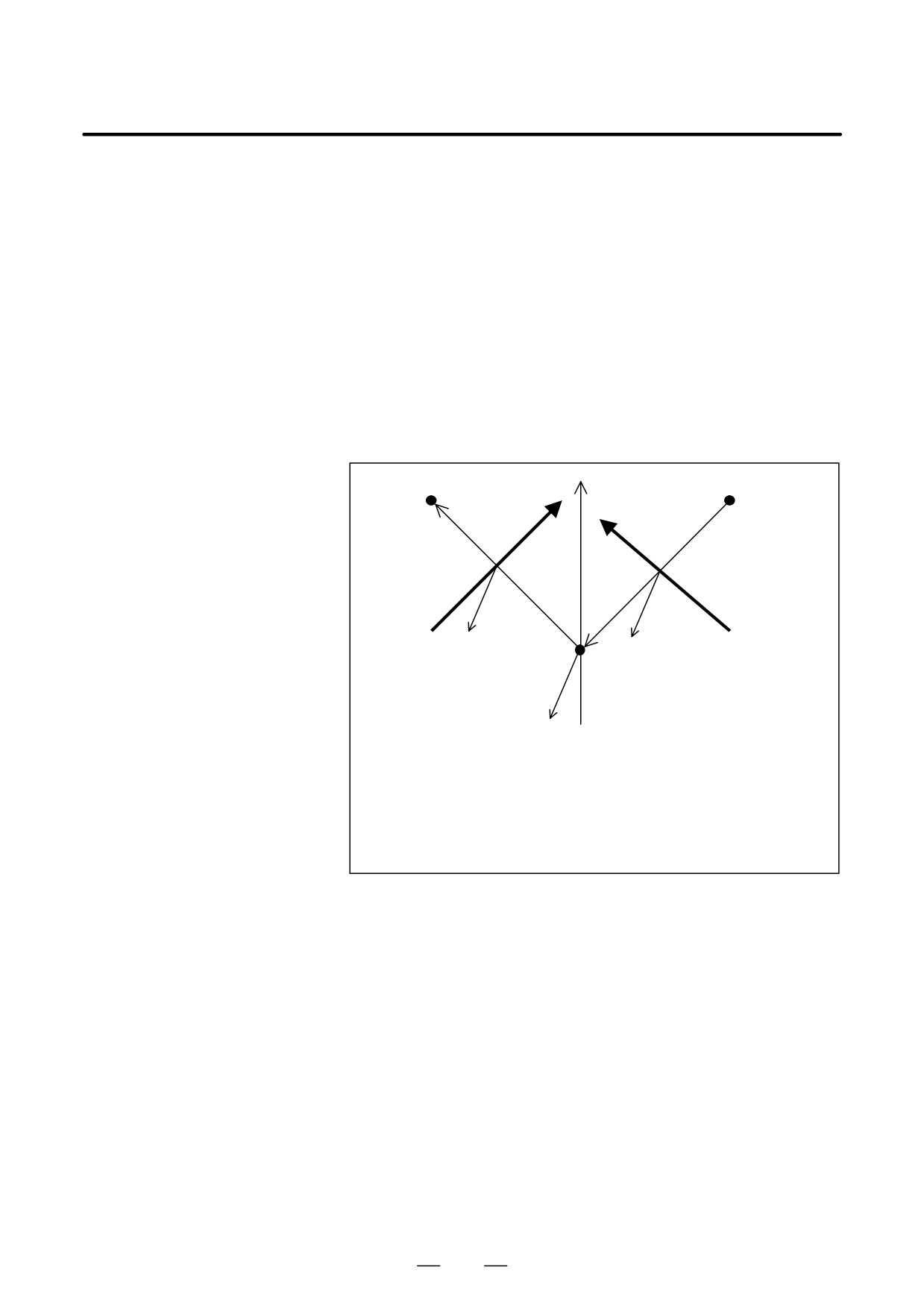
Z
C
A
Vb
Va
45°
46°
B
Y
Va: Tool direction vector when A = -46
Vb: Tool direction vector when A=45
A : End point of N3
B : End point of N4
C : End point of N6
Fig. 22.5.1 (o) Tool Direction Vector
e3
e2
V2
B’
C’
A’
V1
A’ : Point A projected onto the compensation plane
B’ : Point B projected onto the compensation plane
C’ : Point C projected onto the compensation plane
Fig. 22.5.1 (p) Compensation Vector at the End Point (Point B) of N4
(on Compensation Plane)
678
B-63534EN/02
PROGRAMMING
22. RISC PROCESSOR
The move direction of A’B’ is opposite to that of B’C’, so that two
compensation vectors, V1 and V2, are produced at point B’ (end point of
N4). There is a possibility of overcutting in this case, so an alarm
(PS0272) is issued from N4.
(1) Conditions for issuing the interference alarm
Suppose that the tool direction vector changes considerably from one
block to another due to a move command for a rotation axis. In this
case, an interference alarm is assumed because compensation vectors
are regarded as being generated in the wrong directions when the path
angle difference on the compensation plane is large, even though the
angle difference of the directions of compensation vectors to be
generated by those blocks is small.
Here, the compensation plane is perpendicular to the tool direction
(Va in Fig. 14.14.1(q)) of the first of the two blocks.
Specifically, the conditions below are used for issuing the alarm.
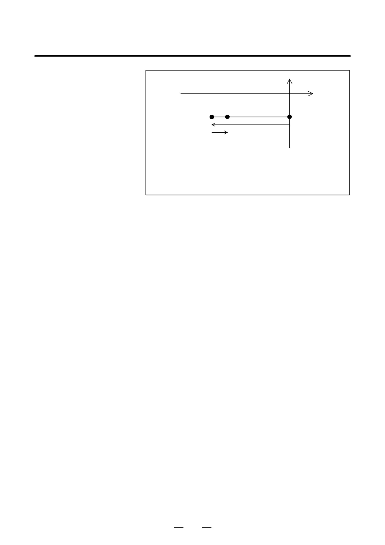
Z
C
A
Vb
Va
Ua
Ub
Wb
Wa
B
Y
X
Ua : Vector AB
Ub : Vector BC
Va : Tool direction vector between A and B
Vb : Tool direction vector between B and C
Wa : Va Ua
Wb : Vb Ub
(Here, represents an outer product operator.)
Fig. 22.5.1 (q) Conceptual Diagram
679
22.
RISC PROCESSOR
PROGRAMMING
B-63534EN/02
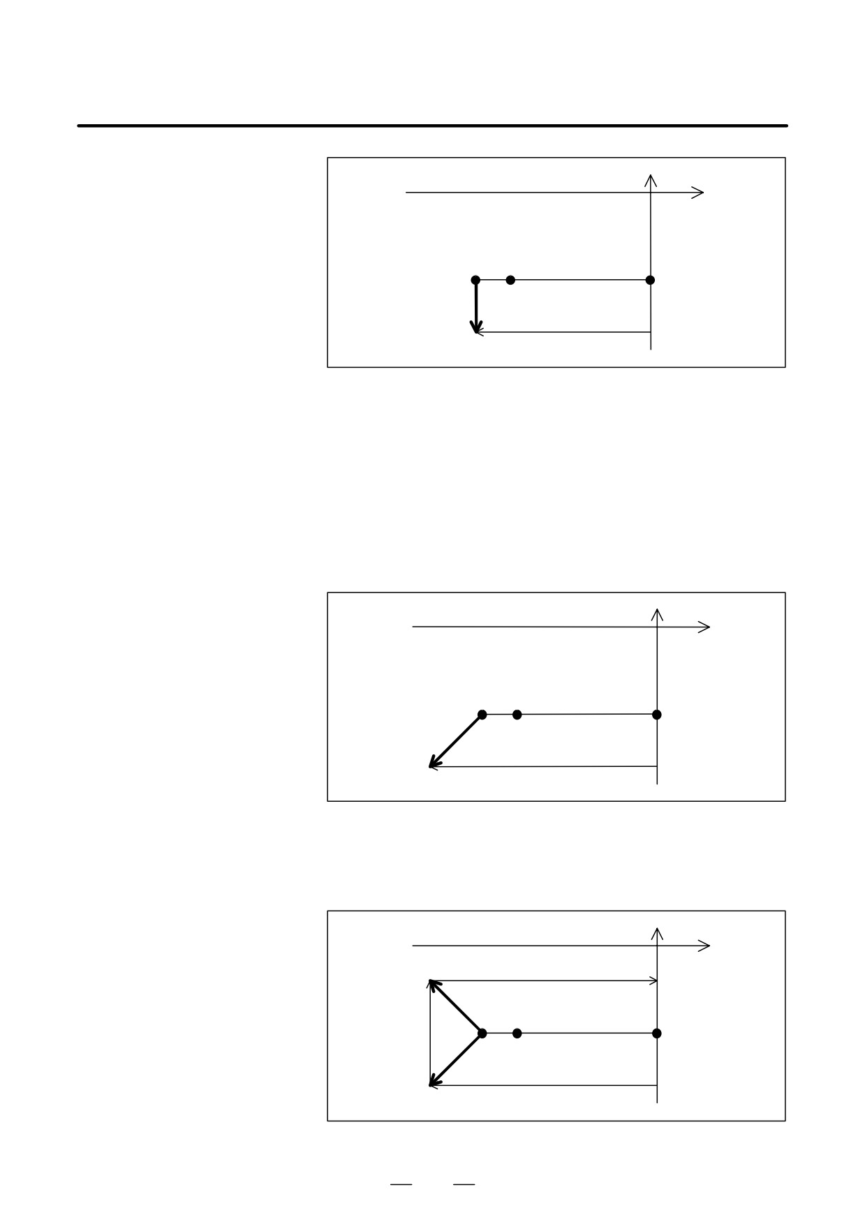
e3
e2
B’
C’
A’
Ra
Rb
A’
: Point A projected onto the compensation plane
B’ : Point B projected onto the compensation plane
C’ : Point C projected onto the compensation plane
Ra : Vector A’B’
Rb : Vector B’C’
Fig. 22.5.1 (r) Programmed Path (on the Compensation Plane) before and
after the End Point (Point B) of N4
When all the following conditions are satisfied, an alarm (PS0272)
Issued.
(a) The tool direction vector changes remarkably.
a : Angle for determination set in parameter No. 6261 (The default
is 45°.)
(Va,Vb) v cos(a)(Here, (Va,Vb) means an inner product.)
(b) The difference between the directions of the compensation vectors
to be generated is small.
Wa : Direction of a compensation vector to be generated by the AB
block.
Wb : Direction of a compensation vector to be generated by the BC
block.
Wa = Va Ua
Wb = Vb Ub
(Wa,Wb) w 0
(c) The path angle difference on the compensation plane is large.
(Ra,Rb) < 0
(2) Suppressing the issue of the alarm with a Q command
By inserting a Q command into a block that issued the alarm, the issue
of the alarm can be suppressed.
(a) Q1 command
By inserting a Q1 command, a vertical vector is generated.
Example) N4 Y-200 Z-200 Q1
680
B-63534EN/02
PROGRAMMING
22. RISC PROCESSOR
e3
e2
B’
C’
A’
V
At point B’, a vector (V) perpendicular to A’B’ is generated.
Fig. 22.5.1 (s) Q1 Command
A vertical vector can also be generated by specifying G41.2 or
G42.1 in the next block as indicated in the example below.
Example) N6 G41.2 Y-400 Z0
(b) Q2 command
With a program specifying a linear-to-linear connection, up to two
compensation vectors are generated. In this case, the second vector
is deleted by inserting a Q2 command. The Q2 command has no
effect on circular interpolation.
Example) N4 Y-200 Z-200 Q2
e3
e2
B’
C’
A’
V1
The second vector (V2) is deleted, and only V1 is used as a compensation vector.
Fig. 22.5.1 (t) Q2 Command
(c) Q3 command
By inserting a Q3 command, the issue of the alarm can be suppressed.
Example) N4 Y-200 Z-200 Q3
e3
e2
V2
B’
C’
A’
V1
The two vectors (V1 and V2) are not deleted.
Fig. 22.5.1 (u) Q3 Command
681
22. RISC PROCESSOR
PROGRAMMING
B-63534EN/02
22.5.2
Leading edge offset is a type of cutter compensation that is used when a
workpiece is machined with the edge of a tool. A tool is automatically
Leading Edge Offset
shifted by a specified cutter compensation value on the line where a plane
formed by a tool direction vector and tool movement direction intersects
a plane perpendicular to the tool axis direction.
Tool vector
Tool used
Reference
tool
Tool center path
(after
compensation)
Programmed
Cutter compensation
tool path
vector
Cutter compensation
amount
Fig. 22.5.2 (a) Reading edge offset
Format
D Leading edge offset
G41.3 D_ ;
D Leading edge offset
cancel
G40 ;
NOTE
1
G41.3 can be specified only in the G00 or G01 mode. In a
block containing G41.3 or G40, only the addresses D, O,
and N can be specified.
2
The block after a block containing a G41.3 command must
contain a move command. In that block, however, tool
movement in the same direction as the tool axis direction or
the opposite direction cannot be specified.
3
No continuous-state G code that belongs to the same
group as G00 and G01 can be specified in the G41.3 mode.
Explanations
D Operation at
Unlike tool side compensation the operation performed at leading edge
compensation start-up
compensation start-up and cancellation does not vary. When G41.3 is
and cancellation
specified, the tool is moved by the amount of compensation (VC) in the
plane formed by the movement vector (VM) of the block after a G41.3
block and the tool vector (VT) obtained at the time of G41.3 specification.
The tool movement is perpendicular to the tool vector. When G40 is
specified, the tool is moved to cancel VC. The following illustrates how
the compensation is performed.
682
B-63534EN/02
PROGRAMMING
22. RISC PROCESSOR
(1) When the tool vector is inclined in the direction the tool moves
: Tool center path
: Programmed tool path
Tool vector(VT)
Tool
G41.3(VC)
VM
G40
Fig. 22.5.2 (b) When the tool vector is inclined in the direction the tool
moves
(2) When the tool vector is inclined in the direction opposite to the
direction the tool moves
: Tool center path
: Programmed tool path
Tool vector(VT)
Tool
G41.3(VC)
VM
G40
Fig. 22.5.2 (c) When the tool vector is inclined in the direction opposite to
the direction the tool moves
D Operation in the
The tool center moves so that a compensation vector (VC) perpendicular
compensation mode
to the tool vector (VT) is created in the plane formed by the tool vector
(VT) at the end point of each block and the movement vector (VM) of the
next block.
Tool center path (after compensation)
VT2
VT1
VC1
VC2
Programmed tool path
V
M1
VM3
VM2
VMn: Movement vector of block n
VTn : Tool vector at the end of block n
VCn : Compensation vector of block n (that lies in the VTn- VMn+1 plane, and is
perpendicular to VTn)
Fig. 22.5.2 (d) Operation in the compensation mode
If a G code or M code that suppresses buffering is specified in the
compensation mode, however, the compensation vector created
immediately before the specification is maintained.
When a block involving no movement (including a block containing a
move command for a rotation axis only) is specified, the movement vector
of the block after the block involving no movement is used to create a
compensation vector as shown below.
683
22. RISC PROCESSOR
PROGRAMMING
B-63534EN/02
Tool center path(after compensation)
VT2
VT1
VC1
Programmed path
V
M4
VM1
VM2
VC2 = VC3
There is one block that
specifies no movement.
Fig. 22.5.2 (e) There is one block that specifies no movement.
If block 3 involves no movement, the compensation vector of block 2
(VC2) is created so that it is perpendicular to VT2 and lies in the plane
formed by the movement vector (VM4) of block 4 and the tool vector
(VT2) at the end point of block 2.
NOTE
If two or more successive blocks involve no movement, the
previously created compensation vector is maintained.
However, such specification should be avoided.
D Block immediately
In the block immediately before the compensation cancel command
before the offset cancel
(G40), a compensation vector is created from the movement vector of that
command (G40)
block and the tool vector at the end point of the block as shown below :
Tool center path (after compensation)
VT2
VT1
G40
VC1
VC2
Programmed path
VM1
VM2
Fig. 22.5.2 (f) Block Immediately before G40
The compensation vector (VC2) of block 2 is created so that it is
perpendicular to VT2 and lies in the plane formed by the tool vector (VT2)
at the end point of block 2 and the movement vector (VM2) of block 2.
D Method of compensation
In leading edge compensation, the compensation vector is calculated as
vector calculation
follows :
(1) Tool vector
(2) Movement vector
The movement vector (VMn+1) of block n+1 is obtained from the
following expression :
Xn)1 * Xn
Xn : Absolute coordinate value of X axis at
ȱ
ȳ
end point of block n
VMn)1 +ȧ
Yn : Absolute coordinate value of Y axis at
ȲZn)1 *Znȴ
end point of block n
Zn : Absolute coordinate value of Z axis at
end point of block n
(3) Compensation vector
The direction of the compensation vector (VCn) of block n is defined
as follows :
(a) (VMn+1, VTn) > 0 (0deg < q < 90deg.)
684
B-63534EN/02
PROGRAMMING
22. RISC PROCESSOR
VTn
Direction of VCn
VCn
q
(VMn+1
VTn) VTn
VMn+1
VMn+1
q represents the included angle
VCn
q
between VMn+1 and VTn.
(0° v q v 180°)
VTn
Fig. 22.5.2 (g) Direction of the compensation vector (1)
(b) (VMn+1,VTn) < 0 (90deg < q < 180deg.)
VCn
q
Direction of VC1
VTn
- (VMn+1
VTn) VTn
VMn+1
VMn+1
V
Tn
q
VCn
Fig. 22.5.2 (h) Direction of the compensation vector (2)
The compensation vector (VCn) of block n is calculated from VTn and
VMn+1 as described below.
R=Offset value
ȱVTX
ȳ
V +ȧ
ȲVTZȴ
ȱVMX
ȳ
VMn)1 +ȧ
ȲVMZȴ
ȱVX
ȳ
+ (VMn)1 VTn) VTn
V +ȧ
ȲVZȴ
ȱVTZ (VMZVTX *VMXVTZ)*VTY (VMXVTY *VMYVTX)
ȳ
+ȧ
ȲVTY (VMYVTZ *VMZVTY)*VTX (VMZVTX *VMXVTZ)ȴ
Then,
(a) When(VMn+1, VTn) > 0 (0deg. < q < 90deg.)
VX
ȱ
ȳ
R
VCn +
Y
ȧ
ȧ
Ǹ
Vx2 ) Vr2 ) Vz2
ȲV
Z
ȴ
(b) When(VMn+1, VTn) < 0 (90deg. < q < 180deg.)
VX
ȱ
ȳ
*R
VCn +
Y
ȧ
ȧ
Ǹ
Vx2 ) Vr2 ) Vz2
ȲV
Z
ȴ
685
22. RISC PROCESSOR
PROGRAMMING
B-63534EN/02
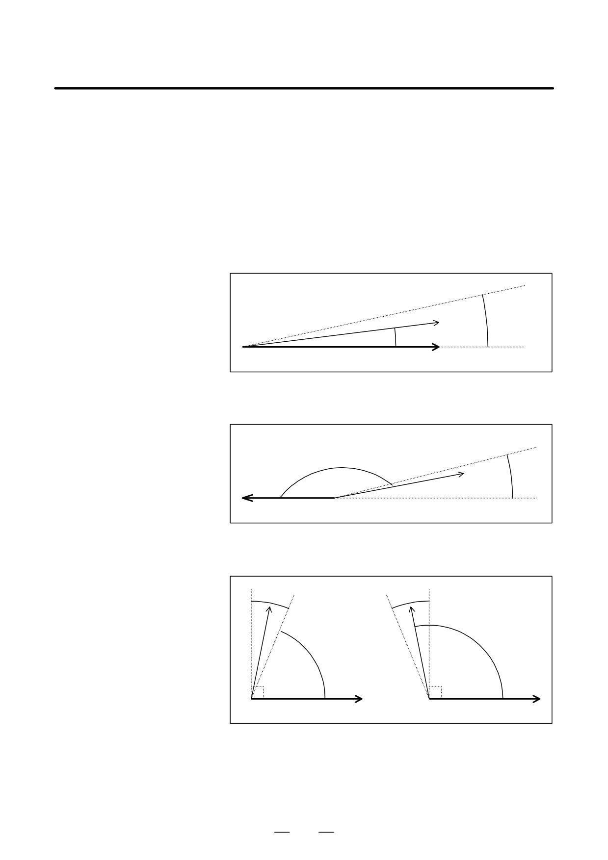
D Compensation
When the included angle q between VMn+1 and VTn is regarded as 0deg.,
performed when q is
180deg., or 90deg., the compensation vector is created in a different way.
approximately 0deg.,
So, when creating an NC program, note the following points :
90deg., or 180deg.
(1) Setting a variation range for regarding q as 0deg., 180deg., or 90deg.
When the included angle (q) between the tool vector (VT) and the
movement vector (VM) becomes approximately 0deg., 180deg., or
90deg., the system regards q as 0deg., 180deg., or 90deg., then
creates a compensation vector which is different from the normal
compensation vector. The variation range used for regarding q as
0deg., 180deg., and 90deg. is or in parameter 6115.
For example, suppose that the angle set in parameter 6115 is Dq.
(a) If 0v q v Dq, q is regarded as 0deg.
∆q
VTn
q
VMn+1
Fig. 22.5.2 (i) Determination of q=0deg.
(b) If (180-Dq)v qv180, q is regarded as 180deg.
q
∆q
VTn
VMn+1
Fig. 22.5.2 (j) Determination of q=180deg.
(c) If (90-Dq)v q v(90+Dq) , q is regarded as 90deg.
∆q
∆q
VTn
VTn
q
q
VMn+1
VMn+1
Fig. 22.5.2 (k) Determination of q=90deg.
(2) Compensation vector when q is regarded as 0deg.or 180deg.
If q is regarded as 0deg.or 180deg.when G41.3 is specified to start
leading edge compensation, alarm PS998 is issued. This means that
the tool vector of the current block and the movement vector of the
686
B-63534EN/02
PROGRAMMING
22. RISC PROCESSOR
next block must not point in the same direction or in opposite
directions at start-up.
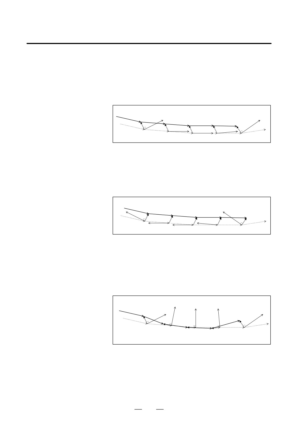
The previously created compensation vector is maintained other than
at start-up at all times.
If the included angles between VT2 and VM3, VT3 andVM4, and VT4
and VM4, and VT4 and VM5 are regarded as 05, the compensation
vector VC1 of block 1 is maintained as the compensation vectors VC2,
VC3, and VC4, of blocks 2, 3, and 4, respectively.
Tool center path
(after compensation)
VT1
VT5
VC1
VC2
VC5
VM1
VT2VC3
VC4
VT3
VT4
VM2
VM6
VM3
Programmed
VM4
VM5
Path
Fig. 22.5.2 (l) When q=0deg.Is Determined
If the included angles between VT2 and VM3, VT3 andVM4, and VT4
and VM5 are regarded as 180deg., the compensation vector VC1 of
block 1 is maintained as the compensation vectors VC2, VC3, and VC4
of blocks 2, 3, and 4, respectively.
Tool center path
(after compensation)
VT5
VT1
VC1
VM2
VC2
VC3
VC5
VM1
VM3
VT4
VC4
VT2
VM6
Programmed
VT3
VM4
VM5
Path
Fig. 22.5.2 (m) When q=180deg. Is Determined
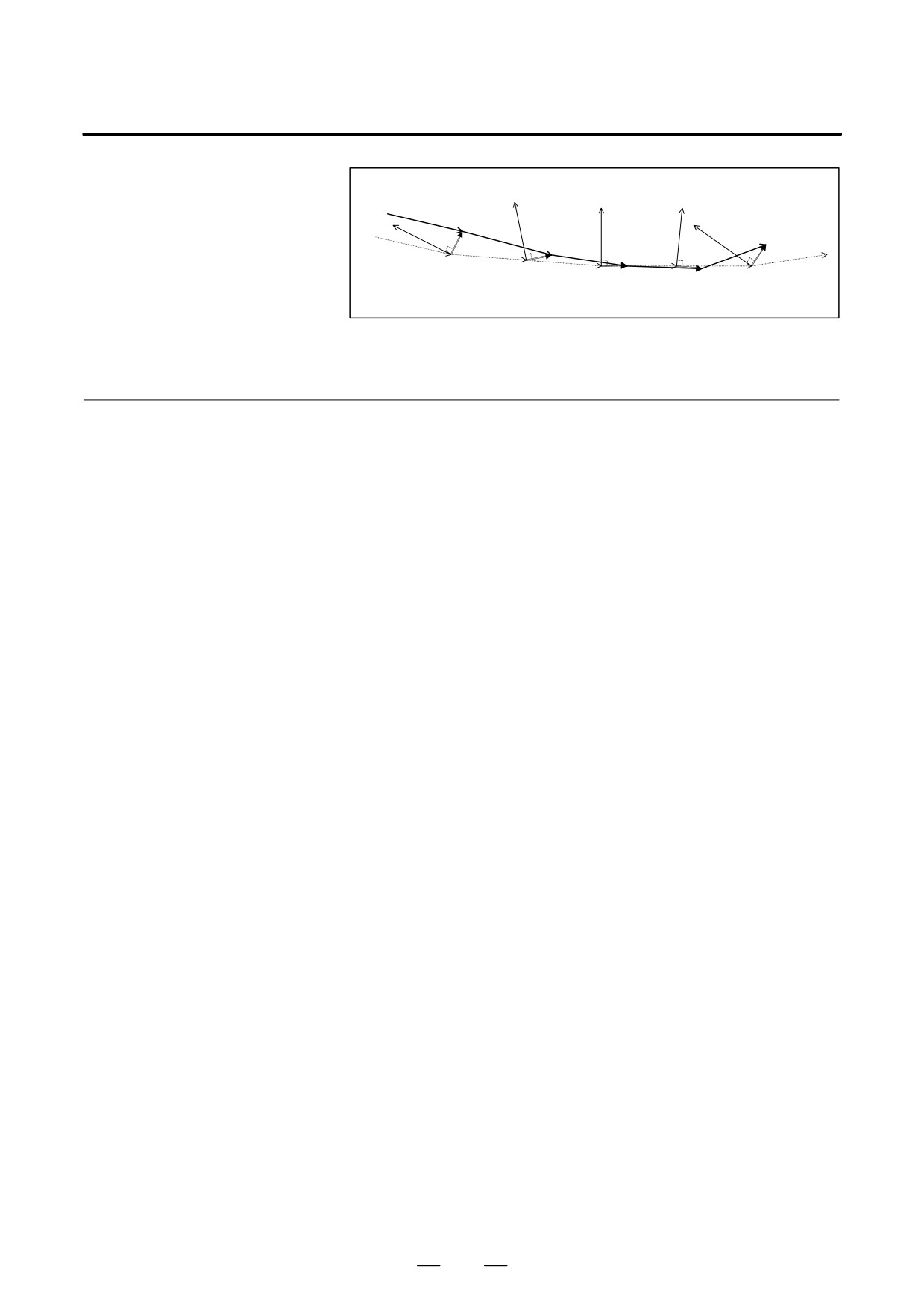
(3) Compensation vector when q is regarded as 90deg.
If the previous compensation vector (VCn-1) points in the opposite
direction ((VMn VTn-1) VTn-1 direction) to VMn with respect to
VTn-1, the current compensation vector (VCn) is created so it points
in the (VMn+1 VTn) VTn direction.
Tool center path
(after compensation)
VT2
VT3
VT4
VT1
VT5
VC1
VC2
V
C5
VM1
VC3
VC4
VM2
VM6
VM3
Programmed
VM4
VM5
Path
Fig. 22.5.2 (n) When q=90deg. Is Determined (1)
If the previous compensation vector
(VCn-1) points in the same
direction ( -(VMn
VTn-1) VTn-1 direction) as VMn with respect to
VTn-1 , the current compensation vector (VCn) is created so it points in the
-(VMn+1 ( VTn) VTn direction.
687
22. RISC PROCESSOR
PROGRAMMING
B-63534EN/02
Tool center path
(after compensation)
VT2
VT3
VT4
VT5
VT1
VC5
VC1
VC2
VM1
VC3
VC4
VM2
VM6
VM3
Programmed
VM4
VM5
Path
Fig. 22.5.2 (o) When q=90deg. Is Determined (2)
22.5.3
Restrictions
D G41.2, G42.2, and G41.3
G41.2, G42.2, G41.3, and G40 are continuous-state G codes that belong
modes
to the same group. Therefore, the G41.2, G42.2, and G41.3 modes cannot
exist at the same time.
D Canned cycle command
Specify a canned cycle command in the compensation cancel mode
(G40).
D Command that must not
In the compensation mode, never successively specify two or more blocks
be specified in two or
that involve no movement. Blocks involving no movement include :
more successive blocks
- M05;
M code output
– S21;
S code output
– G04X1000;
Dwell
– G22X100000;
Machining area setting
– G10P01R100;
Offset value setting
–
(G17)Z2000;
Movement not in the offset plane (movement in
the tool axis direction)
- G90;,O10;,N20; Block containing no move command
- Blocks regarded as involving no movement according to parameter
6114 (for tool side compensation only)
D Reset
Resetting the system in a compensation mode (G41.2, G42.2, or G41.3)
always results in the cancellation mode (G40).
D Limitation of Functions
In the mode for this function, the following functions can be used, but the
condition of each function cannot be changed
- Inch/metric conversion
The alarm is issued when the condition is changed by G20 or G21
command.
- Mirror image
The condition of DI signal cannot be changed.
- Tool life management function
The tool length compensation use the amount of the tool specified by
tool life management function. The command for the tool life
management function have to command before the 3 dimensional
cutter compensation mode.
688
B-63534EN/02
PROGRAMMING
22. RISC PROCESSOR
– One-digit F code feed
The feedrate cannot be changed by using manual pulse generator.
D Commands that cannot
In the mode for this function, the following commands cannot be used.
be specified
The alarm is issued when the following commands are orderd. :
-
Custom macro B
–
Exponentioal interpolation
-G02.3,G03.3
–
Dwell
-G04
–
Function concerning high-speed
-G05
machining
(exclude G05P10000 and 05P0)
-
AI precision control
-G05.1Q1,G5.1Q0
–
Hypothetical axis interpolation
-G07
–
Cylindrical interpolation
-G07.1
–
Advanced preview control
-G08
(Please use AI HPCC function)
-
Polar coordinate interpolation
-G12.1,G13.1
–
Polar coordinate command
-G15,G16
–
Reference position return check
-G27
–
Reference position return
-G28
–
2nd Reference position return
-G30
–
3rd/4th Reference position return
-G30
–
Skip
-G31
–
Threading
-G33
–
Automatic tool length measurement -G37
–
Normal direction control
-G40.1,G41.1,G42.1
–
Cutter compensation B , C
-G41,G42,G39
–
3 dimensional cutter compensation
-G41
–
Wheel wear compensaton
-G41
–
Tool offset
-G45,G46,G47,G48
–
Programmable mirror image
-G50.1,G51.1
–
Local coordinate system
-G52
–
Machine coordinate system
-G53
–
Single direction positioning
-G60
–
Automatic corner override
-G62
–
Tapping mode
-G63
–
Macro call
-G65,G66,G67
(Sub program call is available)
-
Figure copy
-G72.1,G72.2
–
Canned cycles
-G73-G79,G80,G81-G89,
G98,G99
-
Electric gear box
-G80,G81
–
Function for hobbing machine
-G80,G81
–
External motion function
-G81
–
Chopping
-G81.1
689
22. RISC PROCESSOR
PROGRAMMING
B-63534EN/02
– Small-hole peck drilling cycle
-G83
– Changing workpiece coordinate system
-G92
- workpiece coordinate system preset -G92.1
- Feed per revolution
-G95
– Constant surface speed control
-G96,G97
– Infeed control
-G160,G161
– NURBS interpolation
-G06.2
– Workpiece coordinate system
-G54,G54.1,G55,G56,G57,
G58,G59
- M,S,T and B functions with motion command
D Function that cannot be
In the mode for this function, the following functions cannot be used, The
specified
warning message is displayed on the screen when the following functions
are used. :
- MDI intervention
In the mode for this function, the following functions cannot be used, The
alarm(P/S5196) is issued when the following functions are used. :
- Manual interruption operation
- Tool retract and recover
And , in the mode for this function, the following functions cannot be
used.
- Flexible synchronous control
- Sequence number comparison and stop
(The program is not stop at the specified sequence block in 3
dimensional cutter compensation mode.)
- Index table indexing
- Retrace function
Retrace function cannot be used by the program which uses 3
dimensional cutter compensation.
- Rotary axis control
- Gentle normal direction control
- Thc command for the tool life management function
(Tool life time is able to be counted in this mode, but the command for
the tool life management function cannot be used.)
- Macro executor ( Execution macro )
- Manual handle interruption operation
- External deceleration
External decelaration is not available in this mode.
D Others
3 dimensional cutter compensation function cannot be used with the
following function.
- Angular axis control
- Arbitrary angular axis contol
The limitation attaches about the combination of other NC instructions
occasionally.
Please refer to the manual of the each function.
690
B-63534EN/02
PROGRAMMING
22. RISC PROCESSOR
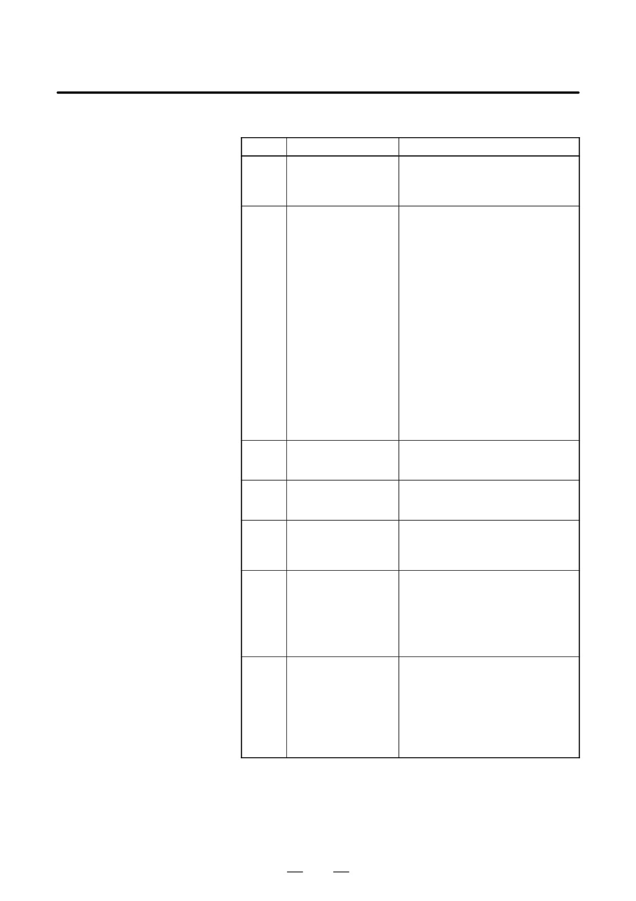
Alarms
Number
Message
Contents
0037
CRC:PLANE CHANGE
An attempt was made to change the
plane in the cutter compensation mode.
To change the plane, cancel the cutter
compensation mode.
0041
CRC:INTERFERENCE
The depth of the cut is too great during
cutter compensation. Check the pro-
gram.
The criteria for judging interference are
as follows:
(1) The direction of movement of the
programmed block differs from the
direction of movement of the corre-
sponding tool center path block by
90° or more or 270° or less.The
check in this case can be disabled
by setting CNC parameter No.
6001#1 to “1”.
(2) In the case of an arc, the difference
in angle between the start and end
points of the programmed block dif-
fers by 180° or more with the differ-
ence in angle between the start and
end points of the corresponding tool
center path block.
0033
CRC:NO INTERSEC-
There is not point of intersection of the
TION
compensated tool center path during
cutter compensation.
5196
ILLEGAL AXIS OPERA-
A function which cannot be used during
TION
HPCC function ¡¡or 5-axis control func-
tion is being executed was commanded.
5405
ILLEGAL PARAMETER
The parameter settings (parameter Nos.
IN G41.2/G42.2
19610 to 19619) for determining the
relationship between the axis of rotation
and the rotation plane are incorrect.
5406
G41.3/G40 FORMAT
(1) A move instruction was specified in
ERROR
a block in which the G41.3 or G40
code is specified.
(2) A G or M code which suppresses
buffering was specified in the block
in which the G41.3 code was speci-
fied.
5407
ILLEGAL COMMAND
(1) A G code other than G00 or G01 in
IN G41.3
group 01 was specified in the G41.3
mode.
(2) An offset (G code in group 07) was
specified in the G41.3 mode.
(3) The block following the block in
which G41.3 (startup) was specified
did not contain a move command.
691

22. RISC PROCESSOR
PROGRAMMING
B-63534EN/02
Number
Message
Contents
5408
G41.3 ILLEGAL
(1) The G41.3 G code (startup) was
START_UP
specified in a group 01 mode for oth-
er than G00 and G01.
(2) The angle formed by the tool direc-
tion vector and the movement direc-
tion vector was 0° or 180° degrees
at startup.
5409
ILLEGAL PARAMETER
The parameter settings (parameter Nos.
IN G41.3
19610 to 19619) for determining the
relationship between the axis of rotation
and the rotation plane are incorrect.
692
B-63534EN/02
PROGRAMMING
22. RISC PROCESSOR
22.6
3-DIMENSIONAL
CIRCULAR
INTERPOLATION
General
Specifying an intermediate and end point on an arc enables circular
interpolation in a 3-dimensional space.
Format
The command format is as follows:
G02.4XX1 YY1 ZZ1 αα1 ββ1 ; First block (mid-point of the arc)
XX1 YY1 ZZ1 αα1 ββ1 ; Second block (end point of the arc)
Or,
G03.4XX1 YY1 ZZ1 αα1 ββ1 ; First block (mid-point of the arc)
XX1 YY1 ZZ1 αα1 ββ1 ; Second block (end point of the arc)
α,β : Arbitrary axes other than the 3-dimensional circular
interpolation axis (up to two axes)
Explanations
D G code group
G02.4 and G03.4 are modal G codes of group 01. They therefore remain
effective until another G code in group 01 is specified.
D Start point, mid-point,
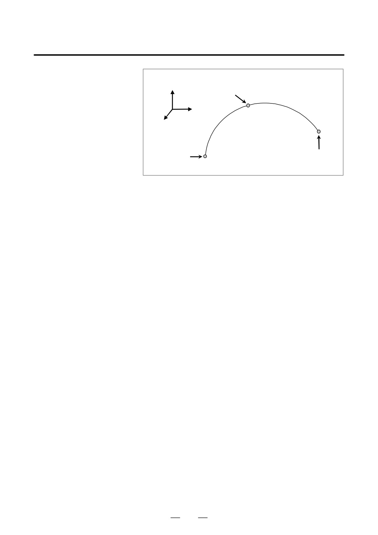
An arc in a 3-dimensional space is uniquely defined with its start point
and end point
(current position) and a specified intermediate point and end point, as
shown below. Two command blocks are used to define this arc. The first
command block specifies the tool path between the start point and
intermediate point. The second command block specifies the tool path
between the intermediate point and end point.
693
22. RISC PROCESSOR
PROGRAMMING
B-63534EN/02
Mid-point
X
(X1,Y1,Z1)
Y
Z
Start point
End point
(X2,Y2,Z2)
Fig.22.6 Start, Mid, and End Points
If the modal code is changed by specifying a code such as G01 with the
end point not specified, the arc cannot be obtained, and alarm PS5432 is
issued. During MDI operation, alarm PS5432 is also issued if a cycle start
is applied with only the mid-point specified.
D Movement along axes
In addition to the 3-dimensional circular interpolation axis (X/Y/Z), up
other than the
to two arbitrary axes (α/β) can be specified at a time. If α/β are omitted
3-dimensional circular
from the first block (mid-point specification) and are specified only in the
interpolation axis
second block (end point specification), the tool moves to the specified
point along the α/β axes during movement from the mid-point of the arc
to the end point. If α/β are omitted from the second block (end point
specification) and are specified only in the first block
(mid-point
specification), the tool moves to the specified point along the α/β axes
during movement from the start point of the arc to the mid-point.
With an incremental command, the position of the mid-point relative to
D Incremental commands
the start point must be specified in the first block, and the position of the
end point relative to the mid-point must be specified in the second block.
D Direction of rotation
The direction of rotation cannot be specified. The movement is the same
regardless of whether G02.4 or G03.4 is specified.
D Single block
When operation is performed using a single block, one cycle start causes
movement from the start point to the end point. A single-block stop is
not performed between the first block (mid-point specification) and the
second block (end point specification).
D Start point assumed if
If 3-dimensional circular interpolations are specified consecutively, the
3-dimensional circular
end point in one interpolation is assumed to be the start point in the next
interpolations are
interpolation.
specified consecutively
D Velocity command
Specify a tangential velocity along an arc in the three-dimensional space.
D Deceleration
In a mode other than AI high-precision contour control mode or AI
nano-based high-precision contour control mode, deceleration is applied
at the end point of the block immediately before the block that commands
three-dimensional circular interpolation or the end point of that block.
Then in-position check is performed.
694
B-63534EN/02
PROGRAMMING
22. RISC PROCESSOR
Limitation
D Cases in which linear
interpolation is
D If the start point, mid-point, and end-point are on the same line, linear
performed
interpolation is performed.
D If the start point coincides with the mid-point, the mid-point
coincides with the end point, or the end point coincides with the start
point, linear interpolation is performed up to the end point.
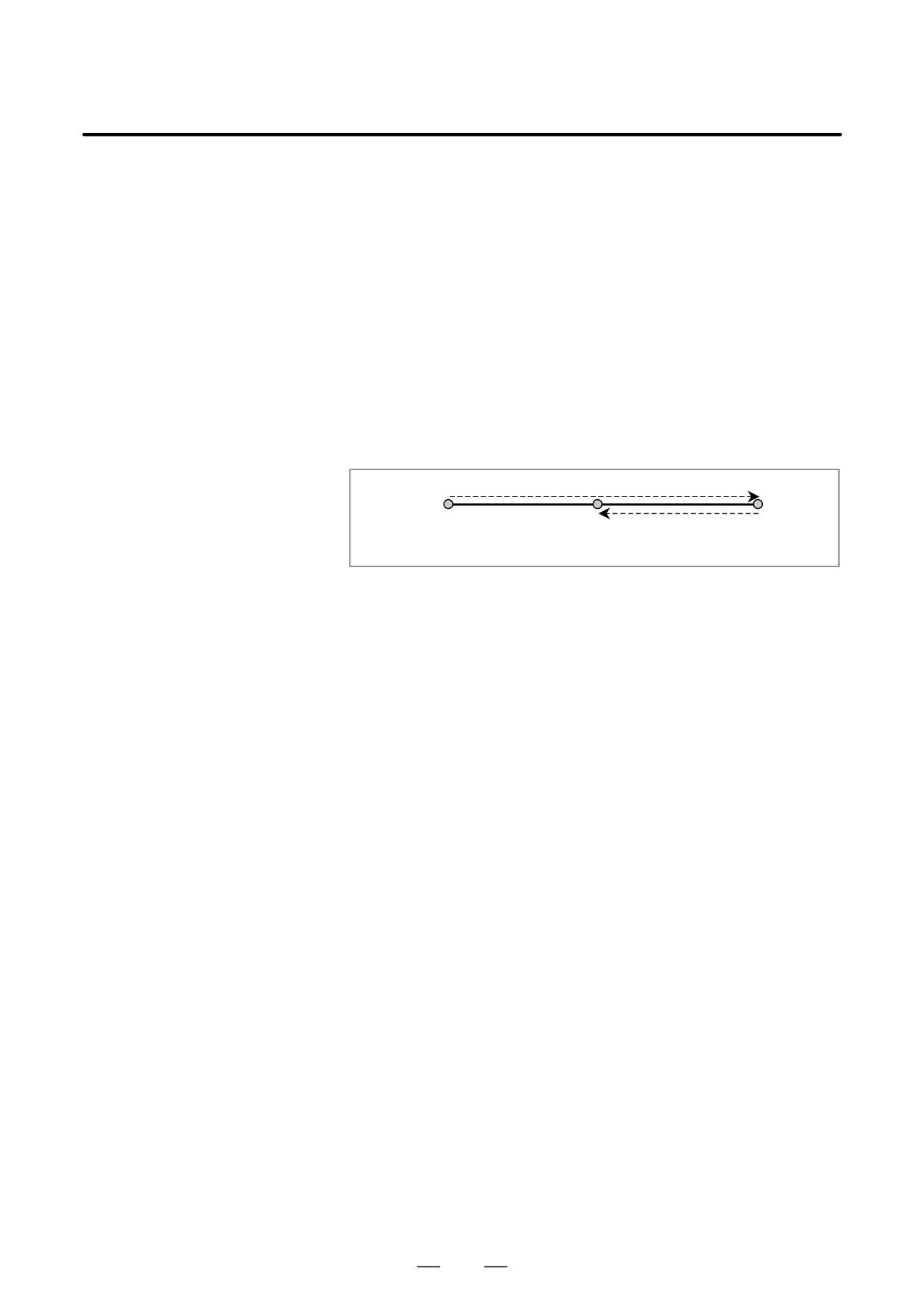
D If the start point, mid-point, and end-point are on the same line and
the end point lies between the start point and the mid-point, the tool
first moves with linear interpolation from the start point to the
mid-point, then returns from the mid-point to the end point with linear
interpolation. Thus, the tool always passes through the specified
point.
Start point
End point
Mid-point
D Whole circles
A whole circle (360 arc) cannot be specified. (This corresponds to the
case in which linear interpolation is performed, as described earlier.)
D Compensation functions
Before using this function, cancel the compensation functions of group
07, such as cutter radius compensation.
D Manual absolute
While this function is in use, manual intervention is not possible with the
manual absolute switch set to the ON position. If intervention is
performed, alarm PS0713 is issued when operation restarts.
D Background graphic
This function cannot be used with background graphic drawing.
D Limitation of Functions
In the mode for this function, the following functions can be used, but the
condition of each function cannot be changed
- Inch/metric conversion
The alarm is issued when the condition is changed by G20 or G21
command.
- Mirror image
The condition of DI signal cannot be changed.
- Tool life management function
The tool length compensation use the amount of the tool specified by
tool life management function. The command for the tool life
management function have to command before the 3 dimensional
cutter compensation mode.
- One-digit F code feed
The feedrate cannot be changed by using manual pulse generator.
695
22. RISC PROCESSOR
PROGRAMMING
B-63534EN/02
D Commands that cannot
In the mode for this function, the following commands cannot be used.
be specified
The alarm is issued when the following commands are orderd. :
-
Custom macro B
–
Exponentioal interpolation
-G02.3,G03.3
–
Dwell
-G04
–
Function concerning high-speed
-G05
machining
(exclude G05P10000 and 05P0)
-
AI precision control
-G05.1Q1,G5.1Q0
–
Hypothetical axis interpolation
-G07
–
Cylindrical interpolation
-G07.1
–
Advanced preview control
-G08
(Please use AI HPCC function)
-
Polar coordinate interpolation
-G12.1,G13.1
–
Polar coordinate command
-G15,G16
–
Reference position return check
-G27
–
Reference position return
-G28
–
2nd Reference position return
-G30
–
3rd/4th Reference position return
-G30
–
Skip
-G31
–
Threading
-G33
–
Automatic tool length measurement -G37
–
Normal direction control
-G40.1,G41.1,G42.1
–
Cutter compensation B , C
-G41,G42,G39
–
3 dimensional cutter compensation
-G41
–
Wheel wear compensaton
-G41
–
Tool offset
-G45,G46,G47,G48
–
Programmable mirror image
-G50.1,G51.1
–
Local coordinate system
-G52
–
Machine coordinate system
-G53
–
Single direction positioning
-G60
–
Automatic corner override
-G62
–
Tapping mode
-G63
–
Macro call
-G65,G66,G67
(Sub program call is available)
-
Figure copy
-G72.1,G72.2
–
Canned cycles
-G73-G79,G80,G81-G89,
G98,G99
-
Electric gear box
-G80,G81
–
Function for hobbing machine
-G80,G81
–
External motion function
-G81
–
Chopping
-G81.1
–
Small-hole peck drilling cycle
-G83
–
Changing workpiece coordinate system
–G92
696
B-63534EN/02
PROGRAMMING
22. RISC PROCESSOR
–
workpiece coordinate system preset -G92.1
–
Feed per revolution
-G95
–
Constant surface speed control
-G96,G97
–
Infeed control
-G160,G161
–
NURBS interpolation
-G06.2
–
Workpiece coordinate system
-G54,G54.1,G55,G56,G57,
G58,G59
-
Three-dimensional coordinate conversion
-G68
-
Coordinate system rotation
-G68
–
Scaling
-G50, G51
–
Programmable mirror image
-G50.1, G51.1
–
Exact stop mode
-G61
–
Cutter compensation
-G40, G41, G42
–
Three-dimensional cutter compensation
-G40, G41.2, G41.3, G42.2
-
Data setting
-G10
–
Exact stop
-G09
–
Miscellaneous function
–
Second auxiliary function
–
Spindle function
–
Tool function
D Function that cannot be
In the mode for this function, the following functions cannot be used, The
specified
warning message is displayed on the screen when the following functions
are used. :
- MDI intervention
In the mode for this function, the following functions cannot be used, The
alarm(P/S5196) is issued when the following functions are used. :
- Manual interruption operation
- Tool retract and recover
And , in the mode for this function, the following functions cannot be
used.
- Flexible synchronous control
- Sequence number comparison and stop
(The program is not stop at the specified sequence block in 3
dimensional cutter compensation mode.)
- Index table indexing
- Retrace function
Retrace function cannot be used by the program which uses 3
dimensional cutter compensation.
- Rotary axis control
- Gentle normal direction control
- Thc command for the tool life management function
(Tool life time is able to be counted in this mode, but the command for
the tool life management function cannot be used.)
697
22. RISC PROCESSOR
PROGRAMMING
B-63534EN/02
– Macro executor ( Execution macro )
- Manual handle interruption operation
- External deceleration
External decelaration is not available in this mode.
- Arbitrary chanfering/Corner rounding
D Others
3 dimensional cutter compensation function cannot be used with the
following function.
- Angular axis control
- Arbitrary angular axis contol
The limitation attaches about the combination of other NC instructions
occasionally.
Please refer to the manual of the each function.
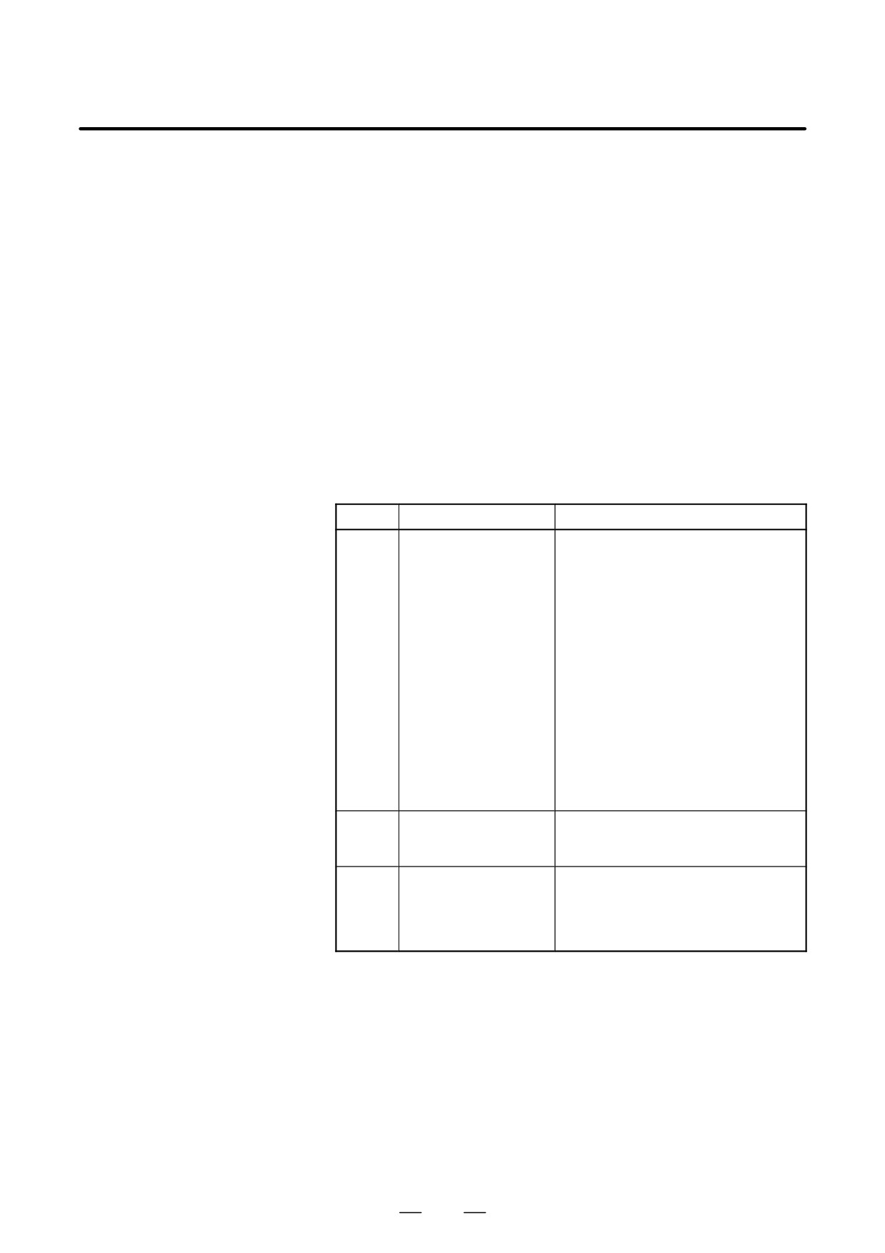
Alarm
Number
Message
Contents
0710
ILLEGAL COMMAND
In a model state in which a 3-dimen-
IN 3-D CIR
sional circular interpolation (G02.4 or
G03.4) cannot be commanded, an at-
tempt for such interpolation was made.
An invalid code was commanded while
in three-dimensional circular interpola-
tion mode. This happens when:
S An M, S, T, or B code was comman-
ded while a command that cancels
three-dimensional circular interpola-
tion was being executed (such a can-
cel command is another G code in
group 01).
S The specified command was not one
that cancels three-dimensional circu-
lar interpolation and includes
G05P10000 or G05P0.
0712
G02.4/G03.4 FORMAT
Three-dimensional circular interpolation
ERROR
(G02.4 or G03.4) was commanded in-
correctly.
0713
MANUAL INTERVEN-
While 3-dimensional circular interpola-
TION IN G02.4/G03.4
tion mode (G02.4 or G03.4) is in prog-
(ABS ON)
ress, manual operation was performed
with the manual absolute switch turned
on.
698
III. OPERATION