FANUC Series 16i/160i/160is-MB, Series 18i/180i/180is-MB5, Series 18i/180i/180is-MB. Operator's Manual - page 15
15. CUSTOM MACRO
PROGRAMMING
B-63534EN/02
Table 15.2 (h) System variable (#3004) for automatic operation control
#3004
Feed hold
Feedrate Override
Exact stop
0
Enabled
Enabled
Enabled
1
Disabled
Enabled
Enabled
2
Enabled
Disabled
Enabled
3
Disabled
Disabled
Enabled
4
Enabled
Enabled
Disabled
5
Disabled
Enabled
Disabled
6
Enabled
Disabled
Disabled
7
Disabled
Disabled
Disabled
S
When the power is turned on, the value of this variable is 0.
S
When feed hold is disabled:
(1) When the feed hold button is held down, the machine stops in the
single block stop mode. However, single block stop operation is not
performed when the single block mode is disabled with variable
#3003.
(2) When the feed hold button is pressed then released, the feed hold lamp
comes on, but the machine does not stop; program execution continues
and the machine stops at the first block where feed hold is enabled.
S
When feedrate override is disabled, an override of 100% is always
applied regardless of the setting of the feedrate override switch on the
machine operator’s panel.
S
When exact stop check is disabled, no exact stop check (position
check) is made even in blocks including those which do not perform
cutting.
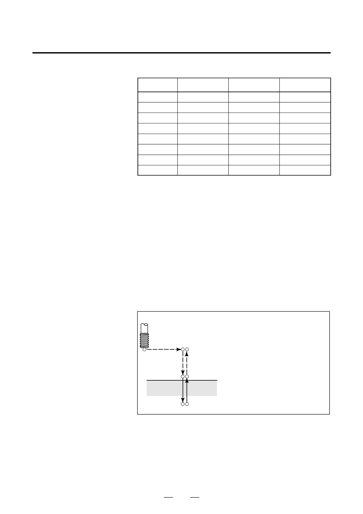
O0001 ;
N1 G00 G91 X#24 Y#25 ;
N2 Z#18 ;
G04 ;
N3 #3003=3 ;
N1
N8, N9,
N4 #3004=7 ;
N10
N5 G01 Z#26 F#9 ;
N2
N6 M04 ;
N7 G01
Z-[ROUND[#18]+ROUND[#26]] ;
N3, N4
G04 ;
N7
N8 #3004=0 ;
N5
N9 #3003=0 ;
N10M03 ;
M99 ;
N6
Fig. 15.2 (a) Example of using variable #3004 in a tapping cycle
400
PROGRAMMING
15. CUSTOM MACRO
B-63534EN/02
D Settings
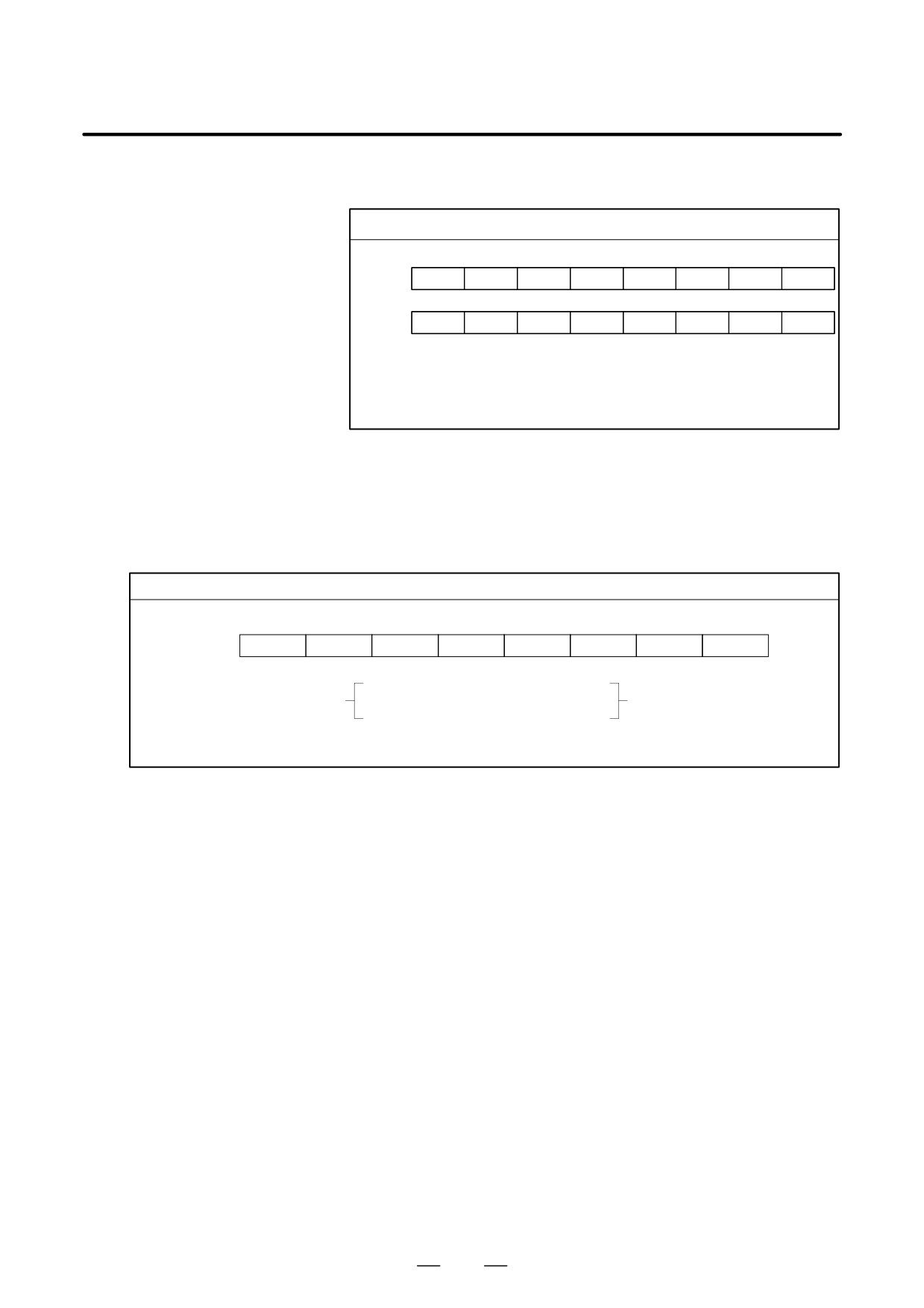
Settings can be read and written. Binary values are converted to
decimals.
#3005
#15
#14
#13
#12
#11
#10
#9
#8
Setting
FCV
#7
#6
#5
#4
#3
#2
#1
#0
Setting
SEQ
INI
ISO
TVC
#9 (FCV)
: Whether to use the FS15 tape format conversion capability
#5 (SEQ) : Whether to automatically insert sequence numbers
#2 (INI)
: Millimeter input or inch input
#1 (ISO)
: Whether to use EIA or ISO as the output code
#0 (TVC)
: Whether to make a TV check
D Mirror image
The mirror-image status for each axis set using an external switch or
setting operation can be read through the output signal (mirror-image
check signal). The mirror-image status present at that time can be
checked. (See III-4.9)
The value obtained in binary is converted into decimal notation.
#3007
#7
#6
#5
#4
#3
#2
#1
#0
Setting
8th axis
7th axis
6th axis
5th axis
4th axis
3th axis
2th axis
1th axis
0 (mirror-image function is disabled)
For each bit,
or
is indicated.
1 (mirror-image function is enabled)
Example : If #3007 is 3, the mirror-image function is enabled for the first and second axes.
S When the mirror-image function is set for a certain axis by both the
mirror-image signal and setting, the signal value and setting value are
ORed and then output.
S When mirror-image signals for axes other than the controlled axes are
turned on, they are still read into system variable #3007.
S System variable #3007 is a write-protected system variable. If an
attempt is made to write data in the variable, P/S 116 alarm “WRITE
PROTECTED VARIABLE” is issued.
401
15. CUSTOM MACRO
PROGRAMMING
B-63534EN/02
D Number of machined
The number (target number) of parts required and the number (completion
parts
number) of machined parts can be read and written.
Table 15.2(i) System variables for the number of parts required and the
number of machined parts
Variable number
Function
#3901
Number of machined parts (completion number)
#3902
Number of required parts (target number)
NOTE
Do not substitute a negative value.
D Modal information
Modal information specified in blocks up to the immediately preceding
block can be read.
Table 15.2 (j) System variables for modal information
Variable number
Function
#4001
G00, G01, G02, G03, G33
(Group 01)
#4002
G17, G18, G19
(Group 02)
#4003
G90, G91
(Group 03)
#4004
(Group 04)
#4005
G94, G95
(Group 05)
#4006
G20, G21
(Group 06)
#4007
G40, G41, G42
(Group 07)
#4008
G43, G44, G49
(Group 08)
#4009
G73, G74, G76, G80-G89
(Group 09)
#4010
G98, G99
(Group 10)
#4011
G50, G51
(Group 11)
#4012
G65, G66, G67
(Group 12)
#4013
G96,G97
(Group 13)
#4014
G54-G59
(Group 14)
#4015
G61-G64
(Group 15)
#4016
G68, G69
(Group 16)
:
:
:
#4022
(Group 22)
#4102
B code
#4107
D code
#4109
F code
#4111
H code
#4113
M code
#4114
Sequence number
#4115
Program number
#4119
S code
#4120
T code
#4130
P code (number of the currently selected addition-
al workpiece coordinate system)
Example:
When #1=#4001; is executed, the resulting value in #1 is 0, 1, 2, 3, or
33.
If the specified system variable for reading modal information
corresponds to a G code group which cannot be used, a P/S alarm is
issued.
402
PROGRAMMING
15. CUSTOM MACRO
B-63534EN/02
D Current position
Position information cannot be written but can be read.
Table 15.2 (k) System variables for position information
Read
Tool com-
Variable
Position
Coordinate
operation
pensation
number
information
system
during
value
movement
#5001-#5008
Block end point
Workpiece
Not
Enabled
coordinate
included
system
#5021-#5028
Current position
Machine
Included
Disabled
coordinate
system
#5041-#5048
Current position
Workpiece
coordinate
#5061-#5068
Skip signal position
system
Enabled
#5081-#5088
Tool length offset
Disabled
value
#5101-#5108
Deviated servo
position
S The first digit (from 1 to 8) represents an axis number.
S The tool length offset value currently used for execution rather than the
immediately preceding tool offset value is held in variables #5081 to
5088.
S The tool position where the skip signal is turned on in a G31 (skip
function) block is held in variables #5061 to #5068. When the skip
signal is not turned on in a G31 block, the end point of the specified
block is held in these variables.
S When read during movement is ”disabled,” this means that expected
values cannot be read due to the buffering (preread) function.
403
15. CUSTOM MACRO
PROGRAMMING
B-63534EN/02
D Workpiece coordinate
Workpiece zero point offset values can be read and written.
system compensation
Table 15.2 (l) System variables for workpiece zero point offset values
values (workpiece zero
point offset values)
Variable
Function
number
#5201
First-axis external workpiece zero point offset value
:
:
#5208
Eighth-axis external workpiece zero point offset value
#5221
First-axis G54 workpiece zero point offset value
:
:
#5228
Eighth-axis G54 workpiece zero point offset value
#5241
First-axis G55 workpiece zero point offset value
:
:
#5248
Eighth-axis G55 workpiece zero point offset value
#5261
First-axis G56 workpiece zero point offset value
:
:
#5268
Eighth-axis G56 workpiece zero point offset value
#5281
First-axis G57 workpiece zero point offset value
:
:
#5288
Eighth-axis G57 workpiece zero point offset value
#5301
First-axis G58 workpiece zero point offset value
:
:
#5308
Eighth-axis G58 workpiece zero point offset value
#5321
First-axis G59 workpiece zero point offset value
:
:
#5328
Eighth-axis G59 workpiece zero point offset value
#7001
First-axis workpiece zero point offset value (G54.1 P1)
:
:
#7008
Eighth-axis workpiece zero point offset value
#7021
First-axis workpiece zero point offset value (G54.1 P2)
:
:
#7028
Eighth-axis workpiece zero point offset value
:
:
#7941
First-axis workpiece zero point offset value (G54.1 P48)
:
:
#7948
Eighth-axis workpiece zero point offset value
#14001
First-axis workpiece zero point offset value (G54.1 P1)
:
:
#14008
Eighth-axis workpiece zero point offset value
#14021
First-axis workpiece zero point offset value (G54.1 P2)
:
:
#14028
Eighth-axis workpiece zero point offset value
:
:
#19980
First-axis workpiece zero point offset value (G54.1 P300)
:
:
#19988
Eighth-axis workpiece zero point offset value
404
PROGRAMMING
15. CUSTOM MACRO
B-63534EN/02
The following variables can also be used:
Axis
Function
Variable number
First axis
External workpiece zero point offset
#2500
#5201
G54 workpiece zero point offset
#2501
#5221
G55 workpiece zero point offset
#2502
#5241
G56 workpiece zero point offset
#2503
#5261
G57 workpiece zero point offset
#2504
#5281
G58 workpiece zero point offset
#2505
#5301
G59 workpiece zero point offset
#2506
#5321
Second
External workpiece zero point offset
#2600
#5202
axis
G54 workpiece zero point offset
#2601
#5222
G55 workpiece zero point offset
#2602
#5242
G56 workpiece zero point offset
#2603
#5262
G57 workpiece zero point offset
#2604
#5282
G58 workpiece zero point offset
#2605
#5302
G59 workpiece zero point offset
#2606
#5322
Third axis
External workpiece zero point offset
#2700
#5203
G54 workpiece zero point offset
#2701
#5223
G55 workpiece zero point offset
#2702
#5243
G56 workpiece zero point offset
#2703
#5263
G57 workpiece zero point offset
#2704
#5283
G58 workpiece zero point offset
#2705
#5303
G59 workpiece zero point offset
#2706
#5323
Fourth axis
External workpiece zero point offset
#2800
#5204
G54 workpiece zero point offset
#2801
#5224
G55 workpiece zero point offset
#2802
#5244
G56 workpiece zero point offset
#2803
#5264
G57 workpiece zero point offset
#2804
#5284
G58 workpiece zero point offset
#2805
#5304
G59 workpiece zero point offset
#2806
#5324
NOTE
To use variables #2500 to #2806 and #5201 to #5328,
optional variables for the workpiece coordinate systems are
necessary.
Optional variables for 48 additional workpiece coordinate
systems are #7001 to #7948 (G54.1 P1 to G54.1 P48).
Optional variables for 300 additional workpiece coordinate
systems are #14001 to #19988 (G54.1 P1 to G54.1 P300).
With these variables, #7001 to #7948 can also be used.
405

15. CUSTOM MACRO
PROGRAMMING
B-63534EN/02
The operations listed in Table 15.3(a) can be performed on variables. The
15.3
expression to the right of the operator can contain constants and/or
ARITHMETIC AND
variables combined by a function or operator. Variables #j and #K in an
LOGIC OPERATION
expression can be replaced with a constant. Variables on the left can also
be replaced with an expression.
Table 15.3 (a) Arithmetic and logic operation
Function
Format
Remarks
Definition
#i=#j
Sum
#i=#j+#k;
Difference
#i=#j-#k;
Product
#i=#j*#k;
Quotient
#i=#j/#k;
Sine
#i=SIN[#j];
An angle is specified in de-
Arcsine
#i=ASIN[#j];
grees. 90 degrees and 30
Cosine
#i=COS[#j];
minutes is represented as
Arccosine
#i=ACOS[#j];
90.5 degrees.
Tangent
#i=TAN[#j];
Arctangent
#i=ATAN[#j]/[#k];
Square root
#i=SQRT[#j];
Absolute value
#i=ABS[#j];
Rounding off
#i=ROUND[#j];
Rounding down
#i=FIX[#j];
Rounding up
#i=FUP[#j];
Natural logarithm
#i=LN[#j];
Exponential function
#i=EXP[#j];
OR
#i=#j OR #k;
A logical operation is per-
XOR
#i=#j XOR #k;
formed on binary numbers
AND
#i=#j AND #k;
bit by bit.
Conversion from BCD to BIN
#i=BIN[#j];
Used for signal exchange
Conversion from BIN to BCD
#i=BCD[#j];
to and from the PMC
Explanations
D Angle units
The units of angles used with the SIN, COS, ASIN, ACOS, TAN, and
ATAN functions are degrees. For example, 90 degrees and 30 minutes is
represented as 90.5 degrees.
D ARCSIN #i = ASIN[#j];
S The solution ranges are as indicated below:
When the NAT bit (bit 0 of parameter 6004) is set to 0: 270_ to 90_
When the NAT bit (bit 0 of parameter 6004) is set to 1: -90_ to 90_
S When #j is beyond the range of -1 to 1, P/S alarm No. 111 is issued.
S A constant can be used instead of the #j variable.
D ARCCOS #i = ACOS[#j];
S The solution ranges from 180° to 0°.
S When #j is beyond the range of -1 to 1, P/S alarm No. 111 is issued.
S A constant can be used instead of the #j variable.
406
PROGRAMMING
15. CUSTOM MACRO
B-63534EN/02
D ARCTAN #i =
S
Specify the lengths of two sides, separated by a slash (/).
ATAN[#j]/[#k];
S
The solution ranges are as follows:
When the NAT bit (bit 0 of parameter 6004) is set to 0: 0o to 360_
[Example] When #1 = ATAN[-1]/[-1]; is specified, #1 is 225.0.
When the NAT bit (bit 0 of parameter 6004) is set to 1: -180_ to 180_
[Example] When #1 = ATAN[-1]/[-1]; is specified, #1 is -135.0.0.
S
A constant can be used instead of the #j variable.
D Natural logarithm #i =
S
Note that the relative error may become 10-8 or greater.
LN[#j];
S
When the antilogarithm (#j) is zero or smaller, P/S alarm No. 111 is
issued.
S
A constant can be used instead of the #j variable.
D Exponential function #i =
S
Note that the relative error may become 10-8 or greater.
EXP[#j];
S
When the result of the operation exceeds 3.65 X 1047 (j is about 110),
an overflow occurs and P/S alarm No. 111 is issued.
S
A constant can be used instead of the #j variable.
D ROUND function
S
When the ROUND function is included in an arithmetic or logic
operation command, IF statement, or WHILE statement, the ROUND
function rounds off at the first decimal place.
Example:
When #1=ROUND[#2]; is executed where #2 holds 1.2345, the value
of variable #1 is 1.0.
S When the ROUND function is used in NC statement addresses, the
ROUND function rounds off the specified value according to the least
input increment of the address.
Example:
Creation of a drilling program that cuts according to the values of
variables #1 and #2, then returns to the original position
Suppose that the increment system is 1/1000 mm, variable #1 holds
1.2345, and variable #2 holds 2.3456. Then,
G00 G91 X-#1; Moves 1.235 mm.
G01 X-#2 F300; Moves 2.346 mm.
G00 X[#1+#2]; Since 1.2345 + 2.3456 = 3.5801, the travel distance
is
3.580, which does not return the tool to the
original position.
This difference comes from whether addition is performed before or
after rounding off. G00X-[ROUND[#1]+ROUND[#2]] must be
specified to return the tool to the original position.
407

15. CUSTOM MACRO
PROGRAMMING
B-63534EN/02
D Rounding up and down
With CNC, when the absolute value of the integer produced by an
to an integer
operation on a number is greater than the absolute value of the original
number, such an operation is referred to as rounding up to an integer.
Conversely, when the absolute value of the integer produced by an
operation on a number is less than the absolute value of the original
number, such an operation is referred to as rounding down to an integer.
Be particularly careful when handling negative numbers.
Example:
Suppose that #1=1.2 and #2=-1.2.
When #3=FUP[#1] is executed, 2.0 is assigned to #3.
When #3=FIX[#1] is executed, 1.0 is assigned to #3.
When #3=FUP[#2] is executed, -2.0 is assigned to #3.
When #3=FIX[#2] is executed, -1.0 is assigned to #3.
D Abbreviations of
When a function is specified in a program, the first two characters of the
arithmetic and logic
function name can be used to specify the function (See III-9.7).
operation commands
Example:
ROUND → RO
FIX → FI
D Priority of operations
Functions
Operations such as multiplication and division (*, /, AND)
Operations such as addition and subtraction (+, -, OR, XOR)
Example) #1=#2+#3*SIN[#4];
,
and
indicate the order of operations.
D Bracket nesting
Brackets are used to change the order of operations. Brackets can be used
to a depth of five levels including the brackets used to enclose a function.
When a depth of five levels is exceeded, P/S alarm No. 118 occurs.
Example) #1=SIN [ [ [#2+#3] *#4 +#5] *#6] ;
to
indicate the order of operations.
408
PROGRAMMING
15. CUSTOM MACRO
B-63534EN/02
Limitations
D Brackets
Brackets ([, ]) are used to enclose an expression. Note that parentheses
are used for comments.
D Operation error
Errors may occur when operations are performed.
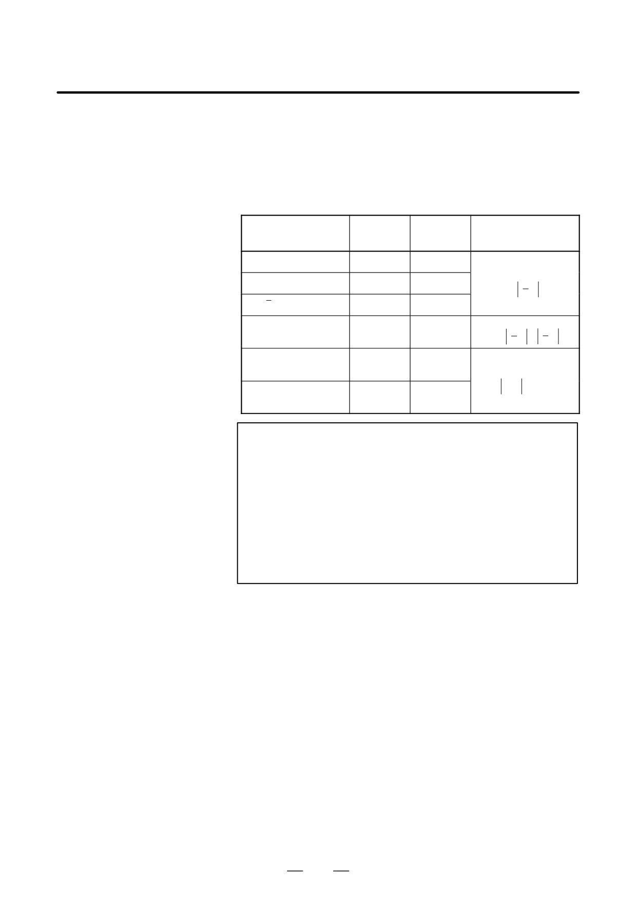
Table 15.3 (b) Errors involved in operations
Average
Maximum
Operation
Type of error
error
error
a = b*c
1.55×10⁻¹⁰
4.66×10⁻¹⁰
Relative error(*1)
a = b / c
4.66×10⁻¹⁰
1.88×10⁻⁹
e
a
Ǹ
1.24×10⁻⁹
3.73×10⁻⁹
a+
b
(*2)
a = b + c
2.33×10⁻¹⁰
5.32×10⁻¹⁰
e
e
a = b - c
Min
b
”
c
a = SIN [ b ]
5.0×10⁻⁹
1.0×10⁻⁸
Absolute error(*3)
a = COS [ b ]
ε
degrees
a = ATAN [ b ] / [ c ]
1.8×10⁻⁶
3.6×10⁻⁶
(*4)
NOTE
1
The relative error depends on the result of the operation.
2
Smaller of the two types of errors is used.
3
The absolute error is constant, regardless of the result of the
operation.
4
Function TAN performs SIN/COS.
5
If the result of the operation by the SIN, COS, or TAN
function is less than 1.0 x 10⁻⁸ or is not 0 because of the
precision of the operation, the result of the operation can be
normalized to 0 by setting bit 1 (MFZ) of parameter No. 6004
to 1.
S The precision of variable values is about 8 decimal digits. When very
large numbers are handled in an addition or subtraction, the expected
results may not be obtained.
Example:
When an attempt is made to assign the following values to variables
#1 and #2:
#1=9876543210123.456
#2=9876543277777.777
the values of the variables become:
#1=9876543200000.000
#2=9876543300000.000
In this case, when #3=#2-#1; is calculated, #3=100000.000 results.
(The actual result of this calculation is slightly different because it is
performed in binary.)
409
15. CUSTOM MACRO
PROGRAMMING
B-63534EN/02
S Also be aware of errors that can result from conditional expressions
using EQ, NE, GE, GT, LE, and LT.
Example:
IF[#1 EQ #2] is effected by errors in both #1 and #2, possibly resulting
in an incorrect decision.
Therefore, instead find the difference between the two variables with
IF[ABS[#1-#2]LT0.001].
Then, assume that the values of the two variables are equal when the
difference does not exceed an allowable limit (0.001 in this case).
S Also, be careful when rounding down a value.
Example:
When #2=#1*1000; is calculated where #1=0.002;, the resulting value
of variable #2 is not exactly 2 but 1.99999997.
Here, when #3=FIX[#2]; is specified, the resulting value of variable
#1 is not 2.0 but 1.0. In this case, round down the value after correcting
the error so that the result is greater than the expected number, or round
it off as follows:
#3=FIX[#2+0.001]
#3=ROUND[#2]
D Divisor
When a divisor of zero is specified in a division or TAN[90], P/S alarm
No. 112 occurs.
410
PROGRAMMING
15. CUSTOM MACRO
B-63534EN/02
The following blocks are referred to as macro statements:
15.4
S Blocks containing an arithmetic or logic operation (=)
MACRO
S Blocks containing a control statement (such as GOTO, DO, END)
STATEMENTS AND
S Blocks containing a macro call command (such as macro calls by
G65, G66, G67, or other G codes, or by M codes)Any block other than
NC STATEMENTS
a macro statement is referred to as an NC statement.
Explanations
D Differences from NC
S Even when single block mode is on, the machine does not stop. Note,
statements
however, that the machine stops in the single block mode when bit 5
of parameter SBM No. 6000 is 1.
S Macro blocks are not regarded as blocks that involve no movement in
the cutter compensation mode (seeII-15.7).
D NC statements that have
S NC statements that include a subprogram call command (such as
the same property as
subprogram calls by M98 or other M codes, or by T codes) and not
macro statements
include other command addresses except an O,N or L address have the
same property as macro statements.
S The blocks not include other command addresses except an O,N,P or
L address have the same property as macro statements.
411
15. CUSTOM MACRO
PROGRAMMING
B-63534EN/02
In a program, the flow of control can be changed using the GOTO
15.5
statement and IF statement. Three types of branch and repetition
BRANCH AND
operations are used:
REPETITION
Branch and repetition
GOTO statement (unconditional branch)
IF statement (conditional branch: if ..., then...)
WHILE statement (repetition while ...)
15.5.1
A branch to sequence number n occurs. When a sequence number outside
of the range 1 to 99999 is specified, P/S alarm No. 128 occurs. A sequence
Unconditional Branch
number can also be specified using an expression.
(GOTO Statement)
GOTO n ; n: Sequence number (1 to 99999)
Example:
GOTO1;
GOTO#10;
15.5.2
Specify a conditional expression after IF.
Conditional Branch
(IF Statement)
IF[<conditional
If the specified conditional expression is satisfied, a branch to sequence
expression>]GOTOn
number n occurs. If the specified condition is not satisfied, the next block
is executed.
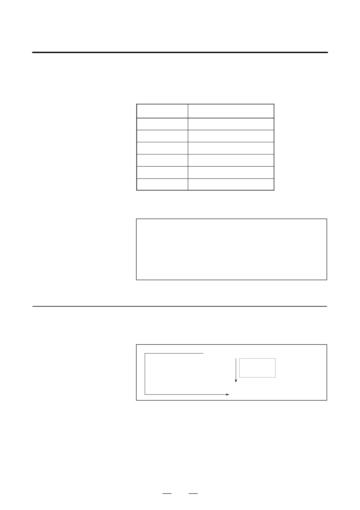
If the value of variable #1 is greater than 10, a branch to sequence number
N2 occurs.
If the condi-
IF [#1 GT 10] GOTO 2 ;
tion is not sa-
tisfied
Processing
If the condition is satisfied
N2 G00 G91 X10.0 ;
:
IF[<conditional
If the specified conditional expression is satisfied, a predetermined macro
expression>]THEN
statement is executed. Only a single macro statement is executed.
If the values of #1 and #2 are the same, 0 is assigned to #3.
IF [#1 EQ #2] THEN#3=0 ;
Explanations
D Conditional expression
A conditional expression must include an operator inserted between two
variables or between a variable and constant, and must be enclosed in
brackets ([, ]). An expression can be used instead of a variable.
412
PROGRAMMING
15. CUSTOM MACRO
B-63534EN/02
D Operators
Operators each consist of two letters and are used to compare two values
to determine whether they are equal or one value is smaller or greater than
the other value. Note that the inequality sign cannot be used.
Table 15.5.2 Operators
Operator
Meaning
EQ
Equal to(=)
NE
Not equal to(0)
GT
Greater than(>)
GE
Greater than or equal to(y)
LT
Less than(<)
LE
Less than or equal to(x)
Sample program
The sample program below finds the total of numbers 1 to 10.
O9500;
#1=0; .
Initial value of the variable to hold the sum
#2=1; .
Initial value of the variable as an addend
N1 IF[#2 GT 10] GOTO 2; . ..Branch to N2 when the addend is greater
than 10
#1=#1+#2; .
Calculation to find the sum
#2=#2+1; .
Next addend
GOTO 1; .
Branch to N1
N2 M30; .
End of program
15.5.3
Specify a conditional expression after WHILE. While the specified
condition is satisfied, the program from DO to END is executed. If the
Repetition
specified condition is not satisfied, program execution proceeds to the
(While Statement)
block after END.
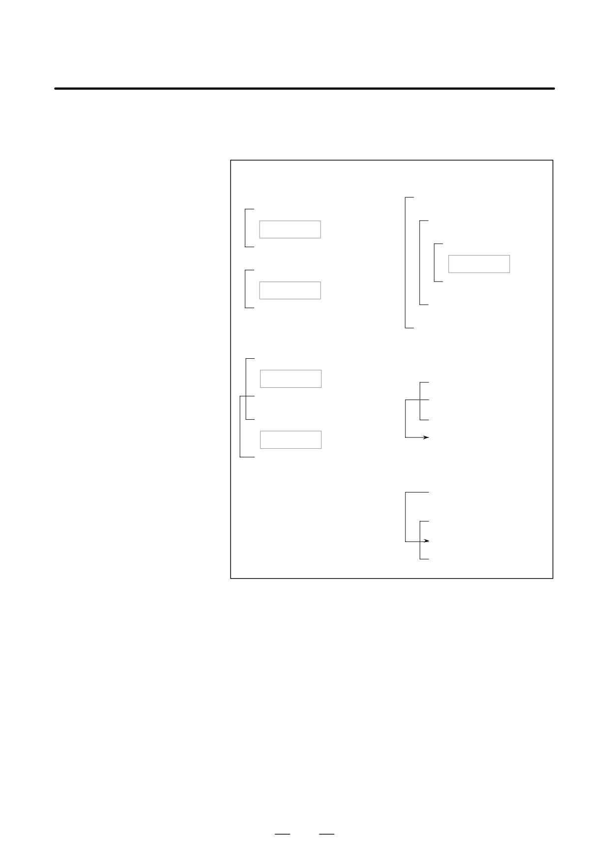
WHILE [conditional expression] DO m ; (m=1,2,3)
If the condi-
If the condi-
Processing
tion is not sa-
tion is satis-
tisfied
fied
END m ;
:
Explanations
While the specified condition is satisfied, the program from DO to END
after WHILE is executed. If the specified condition is not satisfied,
program execution proceeds to the block after END. The same format as
for the IF statement applies. A number after DO and a number after END
are identification numbers for specifying the range of execution. The
numbers 1, 2, and 3 can be used. When a number other than 1, 2, and 3
is used, P/S alarm No. 126 occurs.
413
15. CUSTOM MACRO
PROGRAMMING
B-63534EN/02
D Nesting
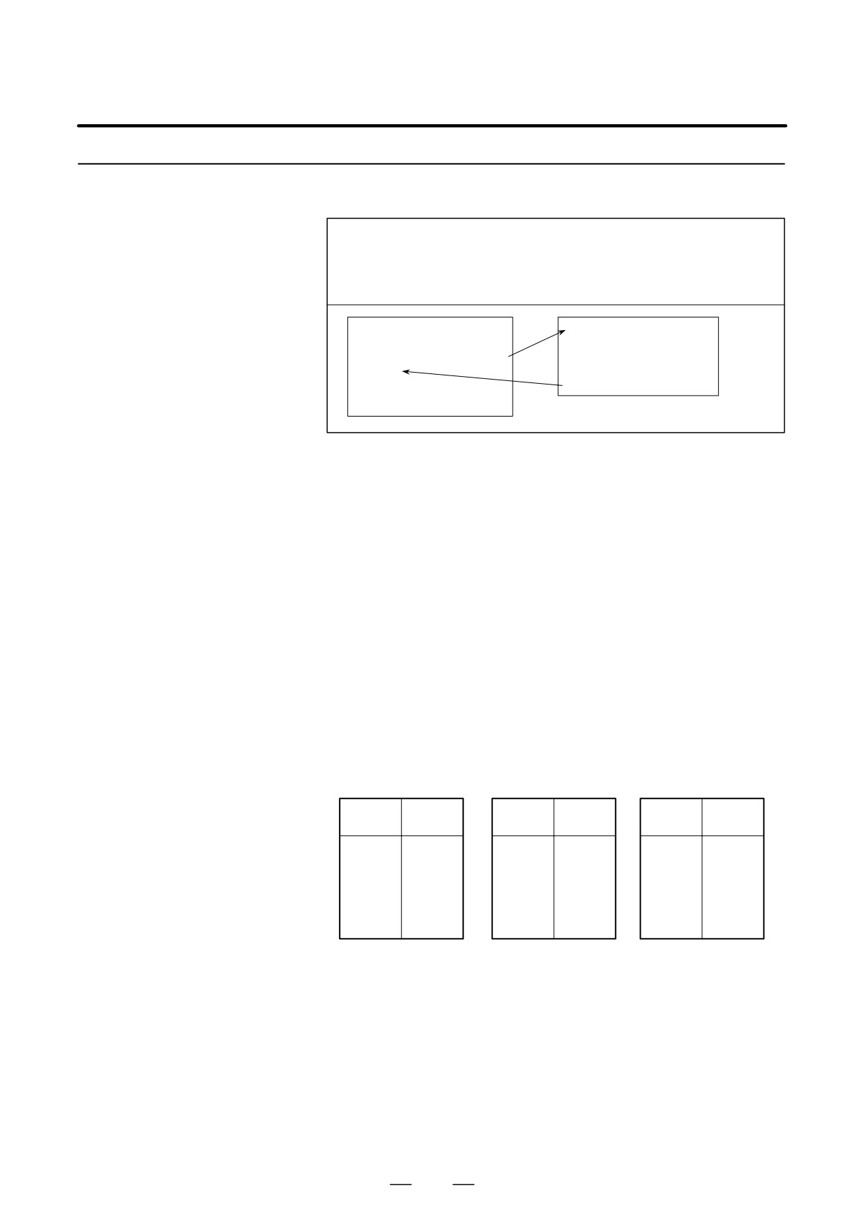
The identification numbers (1 to 3) in a DO-END loop can be used as
many times as desired. Note, however, when a program includes crossing
repetition loops (overlapped DO ranges), P/S alarm No. 124 occurs.
3. DO loops can be nested to
1. The identification numbers
a maximum depth of three lev-
(1 to 3) can be used as many
els.
times as required.
WHILE [ … ] DO 1 ;
WHILE [ … ] DO 1 ;
:
WHILE [ … ] DO 2 ;
Processing
:
END 1 ;
WHILE [ … ] DO 3 ;
:
Processing
WHILE [ … ] DO 1 ;
END 3 ;
Processing
:
END 2 ;
END 1 ;
:
END 1 ;
2. DO ranges cannot overlap.
4. Control can be transferred to
WHILE [ … ] DO 1 ;
the outside of a loop.
Processing
WHILE [ … ] DO 1 ;
WHILE [ … ] DO 2 ;
IF [ … ] GOTO n ;
:
END 1 ;
END 1 ;
Processing
Nn
END 2 ;
5. Branches cannot be made to
a location within a loop.
IF [ … ] GOTO n ;
:
WHILE [ … ] DO 1 ;
Nn … ;
END 1 ;
Limitations
D Infinite loops
When DO m is specified without specifying the WHILE statement, an
infinite loop ranging from DO to END is produced.
D Processing time
When a branch to the sequence number specified in a GOTO statement
occurs, the sequence number is searched for. For this reason, processing
in the reverse direction takes a longer time than processing in the forward
direction. Using the WHILE statement for repetition reduces processing
time.
D Undefined variable
In a conditional expression that uses EQ or NE, a <vacant> and zero have
different effects. In other types of conditional expressions, a <vacant> is
regarded as zero.
414
PROGRAMMING
15. CUSTOM MACRO
B-63534EN/02
Sample program
The sample program below finds the total of numbers 1 to 10.
O0001;
#1=0;
#2=1;
WHILE[#2 LE 10]DO 1;
#1=#1+#2;
#2=#2+1;
END 1;
M30;
415
15. CUSTOM MACRO
PROGRAMMING
B-63534EN/02
A macro program can be called using the following methods:
15.6
Macro call
Simple call (G65)
MACRO CALL
modal call (G66, G67)
Macro call with G code
Macro call with M code
Subprogram call with M code
Subprogram call with T code
Limitations
D Differences between
Macro call (G65) differs from subprogram call (M98) as described below.
macro calls and
S With G65, an argument (data passed to a macro) can be specified. M98
subprogram calls
does not have this capability.
S When an M98 block contains another NC command (for example,
G01 X100.0 M98Pp), the subprogram is called after the command is
executed. On the other hand, G65 unconditionally calls a macro.
S When an M98 block contains another NC command (for example,
G01 X100.0 M98Pp), the machine stops in the single block mode. On
the other hand, G65 does not stops the machine.
S With G65, the level of local variables changes. With M98, the level
of local variables does not change.
416
PROGRAMMING
15. CUSTOM MACRO
B-63534EN/02
15.6.1
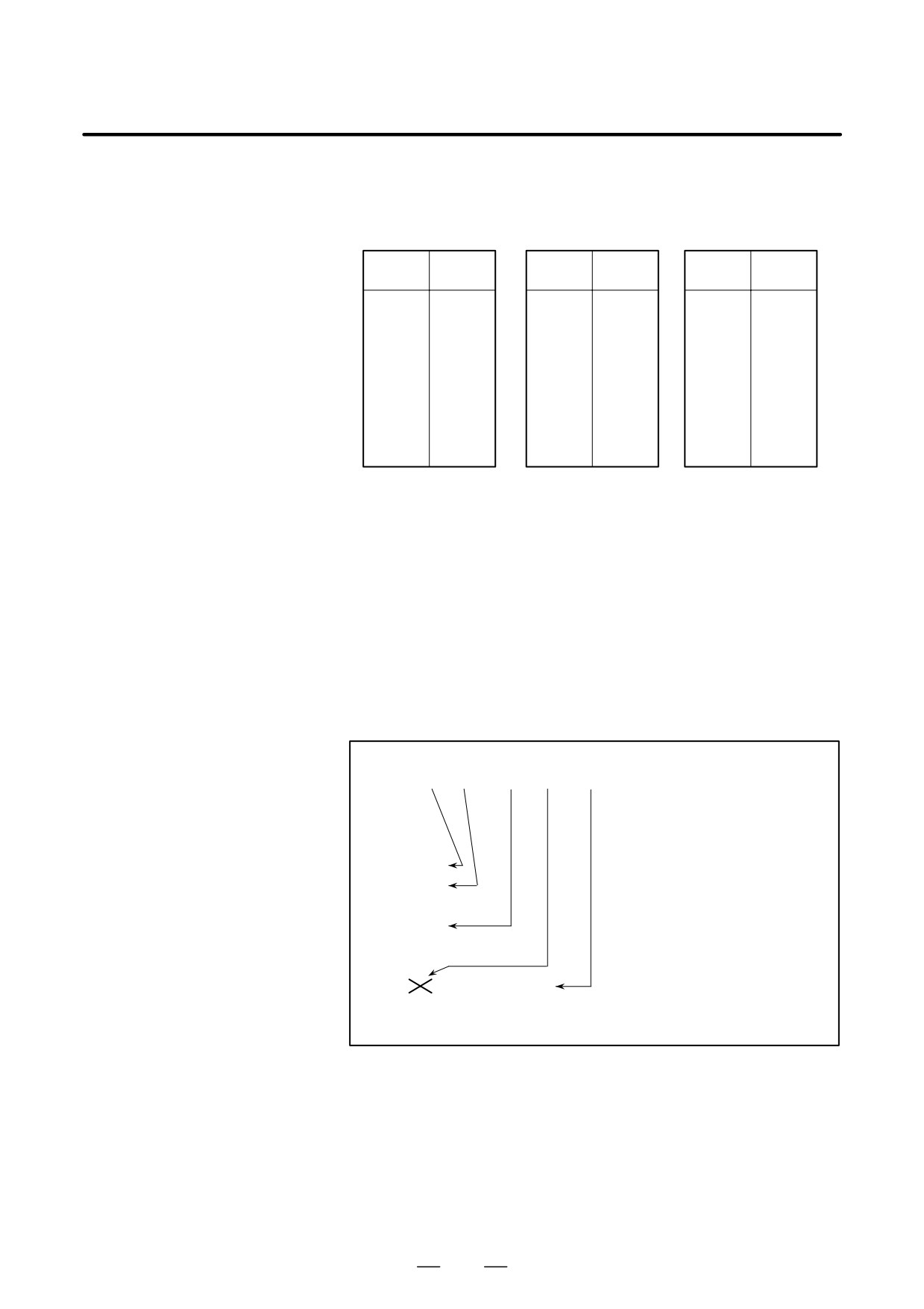
When G65 is specified, the custom macro specified at address P is called.
Data (argument) can be passed to the custom macro program.
Simple Call (G65)
G65 P p L ȏ <argument-specification> ;
P : Number of the program to call
ȏ : Repetition count (1 by default)
Argument : Data passed to the macro
O0001 ;
O9010 ;
:
#3=#1+#2 ;
G65 P9010 L2 A1.0 B2.0 ;
IF [#3 GT 360] GOTO 9 ;
:
G00 G91 X#3 ;
M30 ;
N9 M99 ;
Explanations
D Call
S After G65, specify at address P the program number of the custom
macro to call.
S When a number of repetitions is required, specify a number from 1 to
9999 after address L. When L is omitted, 1 is assumed.
S By using argument specification, values are assigned to corresponding
local variables.
Two types of argument specification are available. Argument
D Argument specification
specification I uses letters other than G, L, O, N, and P once each.
Argument specification II uses A, B, and C once each and also uses I, J,
and K up to ten times. The type of argument specification is determined
automatically according to the letters used.
Argument specification I
Address
Variable
Address
Variable
Address
Variable
number
number
number
A
#1
I
#4
T
#20
B
#2
J
#5
U
#21
C
#3
K
#6
V
#22
D
#7
M
#13
W
#23
E
#8
Q
#17
X
#24
F
#9
R
#18
Y
#25
H
#11
S
#19
Z
#26
S Addresses G, L, N, O, and P cannot be used in arguments.
S Addresses that need not be specified can be omitted. Local variables
corresponding to an omitted address are set to null.
S Addresses do not need to be specified alphabetically. They conform
to word address format.
I, J, and K need to be specified alphabetically, however.
Example
B_A_D_ … J_K_ Correct
B_A_D_ … J_I_ Incorrect
417
15. CUSTOM MACRO
PROGRAMMING
B-63534EN/02
Argument specification II
Argument specification II uses A, B, and C once each and uses I, J, and
K up to ten times. Argument specification II is used to pass values such
as three-dimensional coordinates as arguments.
Address
Variable
Address
Variable
Address
Variable
number
number
number
A
#1
K3
#12
J7
#23
B
#2
I4
#13
K7
#24
C
#3
J4
#14
I8
#25
I1
#4
K4
#15
J8
#26
J1
#5
I5
#16
K8
#27
K1
#6
J5
#17
I9
#28
I2
#7
K5
#18
J9
#29
J2
#8
I6
#19
K9
#30
K2
#9
J6
#20
I10
#31
I3
#10
K6
#21
J10
#32
J3
#11
I7
#22
K10
#33
S Subscripts of I, J, and K for indicating the order of argument
specification are not written in the actual program.
Limitations
D Format
G65 must be specified before any argument.
D Mixture of argument
The CNC internally identifies argument specification I and argument
specifications I and II
specification II. If a mixture of argument specification I and argument
specification II is specified, the type of argument specification specified
later takes precedence.
Example
G65
A1.0 B2.0
I-3.0
I4.0
D5.0
P1000;
<Variables>
#1:1.0
#2:2.0
#3:
#4:-3.0
#5:
#6:
#7:4.0
5.0
When both the I4.0 and D5.0 arguments are commanded for
variable #7 in this example, the latter, D5.0, is valid.
D Position of the decimal
The units used for argument data passed without a decimal point
point
correspond to the least input increment of each address. The value of an
argument passed without a decimal point may vary according to the
system configuration of the machine. It is good practice to use decimal
points in macro call arguments to maintain program compatibility.
D Call nesting
Calls can be nested to a depth of four levels including simple calls (G65)
and modal calls (G66). This does not include subprogram calls (M98).
418
PROGRAMMING
15. CUSTOM MACRO
B-63534EN/02
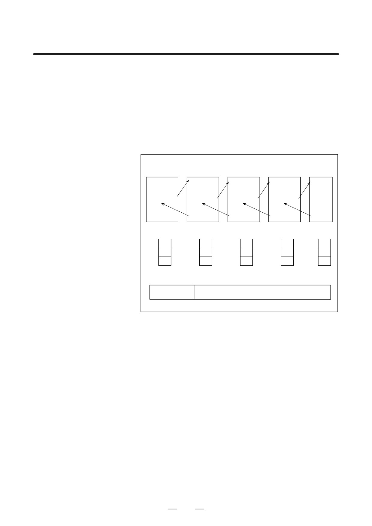
D Local variable levels
S Local variables from level 0 to 4 are provided for nesting.
S The level of the main program is 0.
S Each time a macro is called (with G65 or G66), the local variable level
is incremented by one. The values of the local variables at the previous
level are saved in the CNC.
S When M99 is executed in a macro program, control returns to the
calling program. At that time, the local variable level is decremented
by one; the values of the local variables saved when the macro was
called are restored.
Main program
Macro
(level 0)
Macro (level 1) Macro (level 2) Macro (level 3)
(level 4)
O0001 ;
O0002 ;
O0003 ;
O0004 ;
O0005 ;
:
:
:
:
:
#1=1 ;
#1=2;
#1=3;
#1=4;
#1=5;
G65 P2 A2 ;
G65 P3 A3 ;
G65 P4 A4 ;
G65 P5 A5 ;
:
:
:
:
:
:
:
:
:
:
:
M30 ;
M99 ;
M99 ;
M99 ;
M99 ;
Local variables
(level 0)
(Level 1)
(Level 2)
(Level 3)
(Level 4)
#1
1
#1
2
#1
3
#1
4
#1
5
:
:
:
:
:
:
:
:
:
:
#33
#33
#33
#33
#33
Common variables
#100-, #500-
Variables that can be read from and written to by
macros at different levels
419
15. CUSTOM MACRO
PROGRAMMING
B-63534EN/02
Sample program
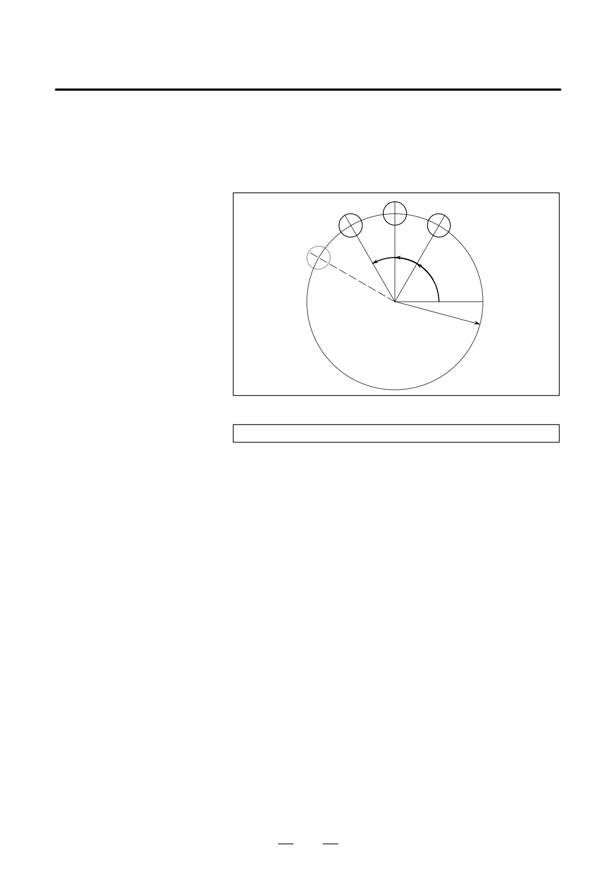
A macro is created which drills H holes at intervals of B degrees after a
(bolt hole circle)
start angle of A degrees along the periphery of a circle with radius I.
The center of the circle is (X,Y). Commands can be specified in either
the absolute or incremental mode. To drill in the clockwise direction,
specify a negative value for B.
H=2
ÉÉ
H=3
H=1
ÉÉ
ÉÉÉÉÉ
ÉÉ
ÉÉÉÉÉ
H=4
B
B
A
Center (X,Y)
Radius I
D Calling format
G65 P9100 X x Y y Z z R r F f I i A a B b H h ;
X: X coordinate of the center of the circle
(absolute or incremental specification)
(#24)
Y: Y coordinate of the center of the circle
(absolute or incremental specification)
(#25)
Z: Hole depth
(#26)
R: Coordinates of an approach point
(#18)
F : Cutting feedrate
(#9)
I
: Radius of the circle
(#4)
A: Drilling start angle
(#1)
B: Incremental angle (clockwise when a negative value is specified)
(#2)
H: Number of holes
(#11)
D Program calling a macro
O0002;
program
G90 G92 X0 Y0 Z100.0;
G65 P9100 X100.0 Y50.0 R30.0 Z-50.0 F500 I100.0 A0 B45.0 H5;
M30;
420

PROGRAMMING
15. CUSTOM MACRO
B-63534EN/02
D Macro program
O9100;
(called program)
#3=#4003; Stores G code of group 3.
G81 Z#26 R#18 F#9 K0; (Note) Drilling cycle.
Note: L0 can also be used.
IF[#3 EQ 90]GOTO 1;
Branches to N1 in the G90 mode.
#24=#5001+#24;
Calculates the X coordinate of
the center.
#25=#5002+#25;
Calculates the Y coordinate of
the center.
N1 WHILE[#11 GT 0]DO 1;
. . . . . . . . . . . . . . . . . . . . . . . . . . Until the number of remaining holes
reaches 0
#5=#24+#4*COS[#1];
Calculates a drilling position on
the X-axis.
#6=#25+#4*SIN[#1];
Calculates a drilling position on
the Y-axis.
G90 X#5 Y#6;
Performs drilling after moving to
the target position.
#1=#1+#2;
Updates the angle.
#11=#11-1;
Decrements the number of holes.
END 1;
G#3 G80;
Returns the G code to the original state.
M99;
Meaning of variables:
#3: Stores the G code of group 3.
#5: X coordinate of the next hole to drill
#6: Y coordinate of the next hole to drill
15.6.2
Once G66 is issued to specify a modal call a macro is called after a block
specifying movement along axes is executed. This continues until G67
Modal Call (G66)
is issued to cancel a modal call.
G66 P p L ȏ <argument-specification> ;
P : Number of the program to call
ȏ : Repetition count (1 by default)
Argument : Data passed to the macro
O0001 ;
O9100 ;
:
:
G66 P9100 L2 A1.0 B2.0 ;
G00 Z-#1 ;
G00 G90 X100.0 ;
G01 Z-#2 F300 ;
Y200.0 ;
:
X150.0 Y300.0 ;
:
G67 ;
:
:
:
M30 ;
M99 ;
421
15. CUSTOM MACRO
PROGRAMMING
B-63534EN/02
Explanations
D Call
S After G66, specify at address P a program number subject to a modal
call.
S When a number of repetitions is required, a number from 1 to 9999 can
be specified at address L.
S As with a simple call (G65), data passed to a macro program is
specified in arguments.
D Cancellation
When a G67 code is specified, modal macro calls are no longer performed
in subsequent blocks.
D Call nesting
Calls can be nested to a depth of four levels including simple calls (G65)
and modal calls (G66). This does not include subprogram calls (M98).
D Modal call nesting
Modal calls can be nested by specifying another G66 code during a modal
call.
Limitations
S In a G66 block, no macros can be called.
S G66 needs to be specified before any arguments.
S No macros can be called in a block which contains a code such as a
miscellaneous function that does not involve movement along an axis.
S Local variables (arguments) can only be set in G66 blocks. Note that
local variables are not set each time a modal call is performed.
Sample program
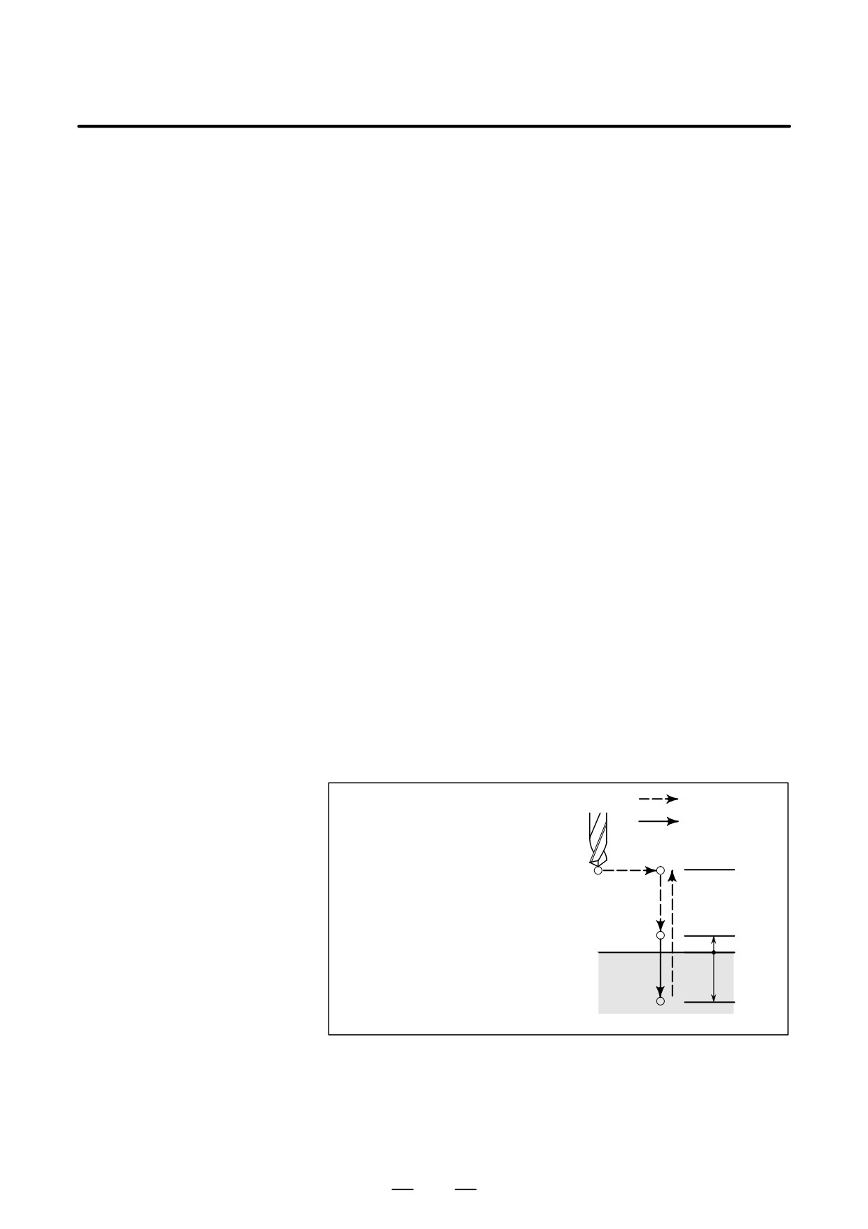
The same operation as the drilling canned cycle G81 is created using a
custom macro and the machining program makes a modal macro call. For
program simplicity, all drilling data is specified using absolute values.
Rapid traverse
The canned cycle consists of the following
basic operations:
Cutting feed
Operation 1:
Operation 1
Position I
Positioning along the X-axis and Y-axis
Operation 2:
Operation 4
Operation 2
Rapid traverse to point R
R
Position R
Operation 3:
Cutting feed to point Z
Z=0
Operation 3
Operation 4:
Rapid traverse to point R or I
Position Z
Z
422

PROGRAMMING
15. CUSTOM MACRO
B-63534EN/02
D Calling format
G65 P9110 X x Y y Z z R r F f L l ;
X: X coordinate of the hole (absolute specification only)
(#24)
Y: Y coordinate of the hole (absolute specification only)
(#25)
Z : Coordinates of position Z (absolute specification only) . . .
(#26)
R : Coordinates of position R (absolute specification only) . . .
(#18)
F : Cutting feedrate
(#9)
L: Repetition count
D Program that calls a
O0001;
macro program
G28 G91 X0 Y0 Z0;
G92 X0 Y0 Z50.0;
G00 G90 X100.0 Y50.0;
G66 P9110 Z-20.0 R5.0 F500;
G90 X20.0 Y20.0;
X50.0;
Y50.0;
X70.0 Y80.0;
G67;
M30;
D Macro program
O9110;
(program called)
#1=#4001;
Stores G00/G01.
#3=#4003;
Stores G90/G91.
#4=#4109;
Stores the cutting feedrate.
#5=#5003;
Stores the Z coordinate at the start of drilling.
G00 G90 Z#18;
Positioning at position R
G01 Z#26 F#9;
Cutting feed to position Z
IF[#4010 EQ 98]GOTO 1; Return to position I
G00 Z#18;
Positioning at position R
GOTO 2;
N1 G00 Z#5;
Positioning at position I
N2 G#1 G#3 F#4;
Restores modal information.
M99;
By setting a G code number used to call a macro program in a parameter,
15.6.3
the macro program can be called in the same way as for a simple call
Macro Call Using
(G65).
G Code
O0001 ;
O9010 ;
:
:
G81 X10.0 Y20.0 Z-10.0 ;
:
:
:
M30 ;
N9 M99 ;
Parameter No.6050 = 81
Explanations
By setting a G code number from 1 to 9999 used to call a custom macro
program (O9010 to O9019) in the corresponding parameter (N0.6050 to
No.6059), the macro program can be called in the same way as with G65.
For example, when a parameter is set so that macro program O9010 can
be called with G81, a user-specific cycle created using a custom macro
can be called without modifying the machining program.
423
15. CUSTOM MACRO
PROGRAMMING
B-63534EN/02
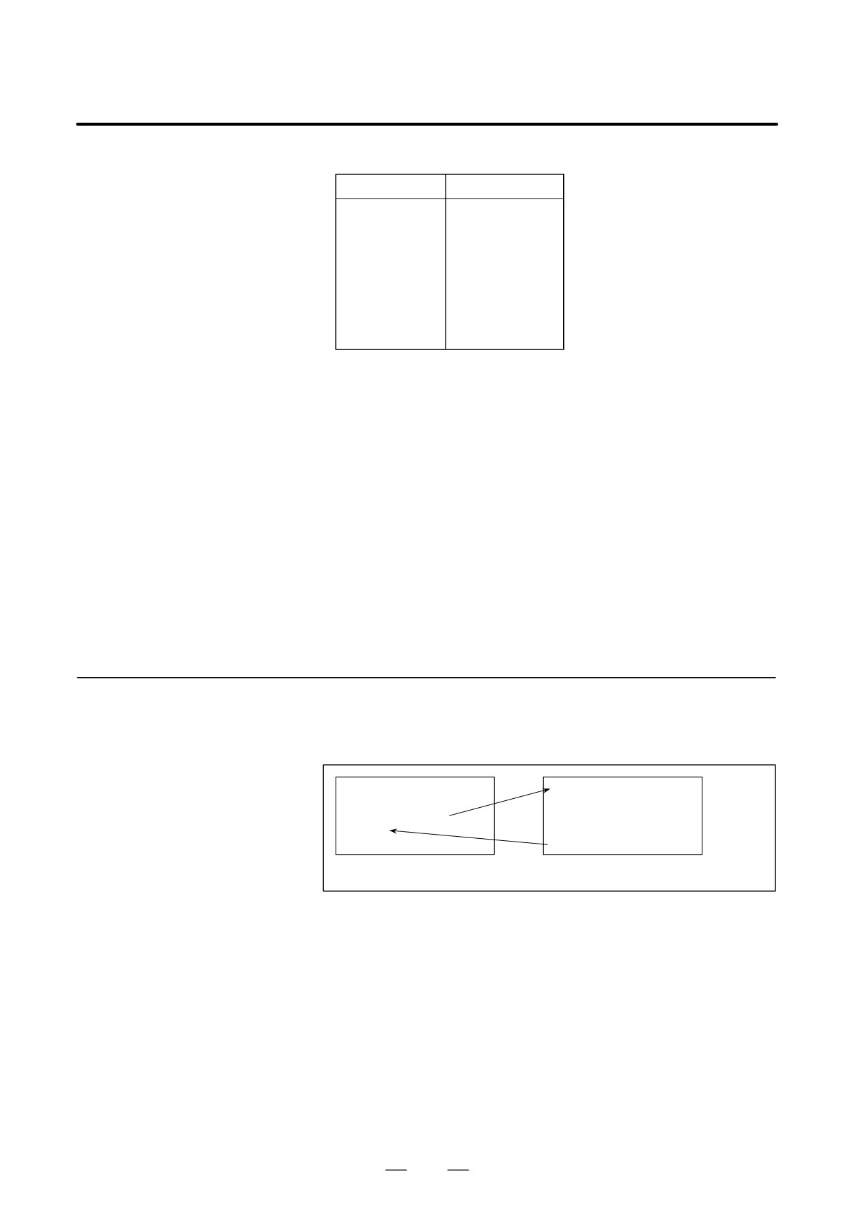
D Correspondence
between parameter
Program number
Parameter number
numbers and program
O9010
6050
numbers
O9011
6051
O9012
6052
O9013
6053
O9014
6054
O9015
6055
O9016
6056
O9017
6057
O9018
6058
O9019
6059
D Repetition
As with a simple call, a number of repetitions from 1 to 9999 can be
specified at address L.
As with a simple call, two types of argument specification are available:
D Argument specification
Argument specification I and argument specification II. The type of
argument specification is determined automatically according to the
addresses used.
Limitations
D Nesting of calls using G
In a program called with a G code, no macros can be called using a G code.
codes
A G code in such a program is treated as an ordinary G code. In a program
called as a subprogram with an M or T code, no macros can be called using
a G code. A G code in such a program is also treated as an ordinary G code.
15.6.4
By setting an M code number used to call a macro program in a parameter,
the macro program can be called in the same way as with a simple call
Macro Call Using an
(G65).
M Code
O0001 ;
O9020 ;
:
:
M50 A1.0 B2.0 ;
:
:
:
M30 ;
M99 ;
Parameter No.6080 = 50
Explanations
By setting an M code number from 1 to 99999999 used to call a custom
macro program (9020 to 9029) in the corresponding parameter (No.6080
to No.6089), the macro program can be called in the same way as with
G65.
424
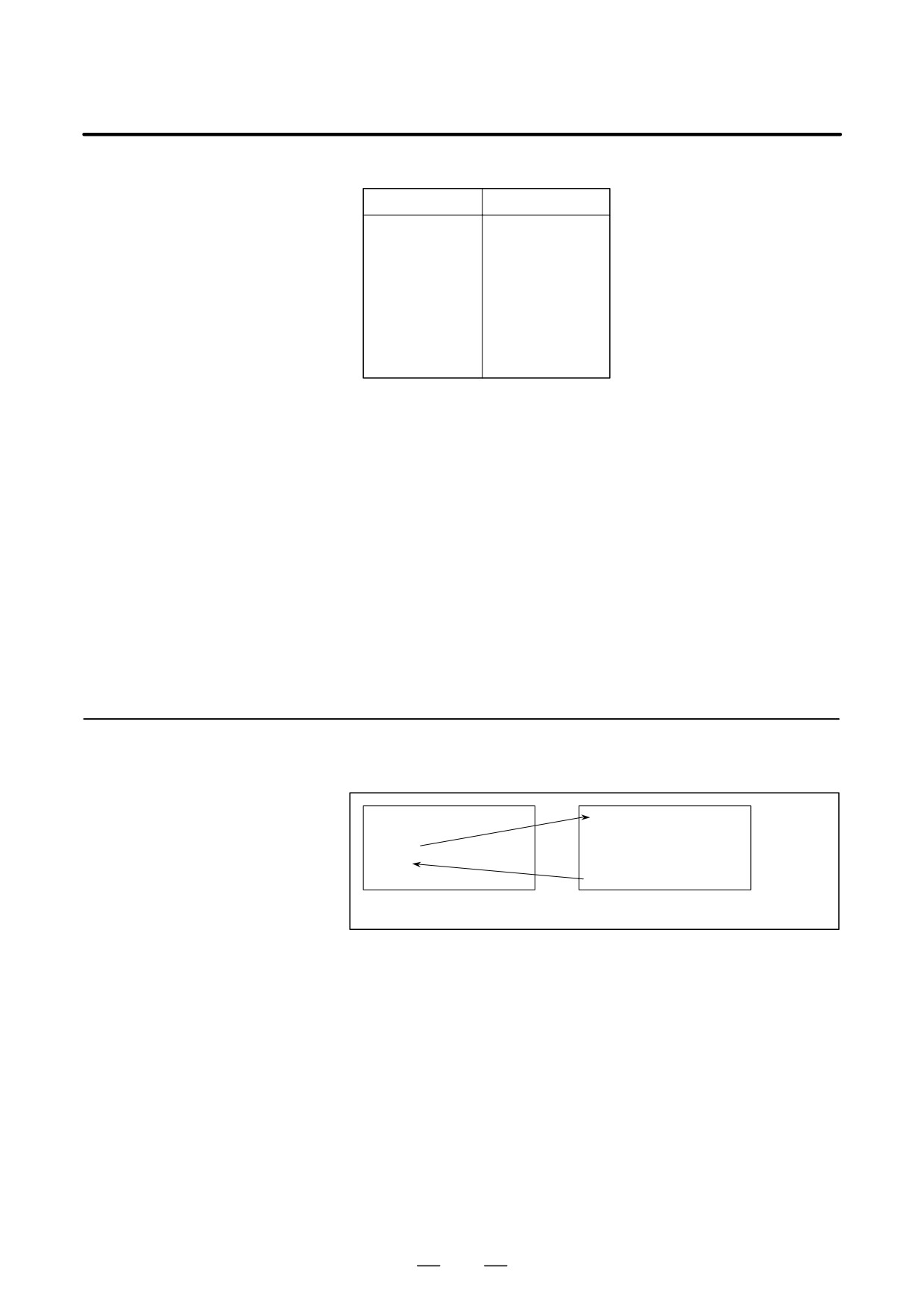
PROGRAMMING
15. CUSTOM MACRO
B-63534EN/02
D Correspondence
between parameter
Program number
Parameter number
numbers and program
O9020
6080
numbers
O9021
6081
O9022
6082
O9023
6083
O9024
6084
O9025
6085
O9026
6086
O9027
6087
O9028
6088
O9029
6089
D Repetition
As with a simple call, a number of repetitions from 1 to 9999 can be
specified at address L.
As with a simple call, two types of argument specification are available:
D Argument specification
Argument specification I and argument specification II. The type of
argument specification is determined automatically according to the
addresses used.
Limitations
S An M code used to call a macro program must be specified at the start
of a block.
S In a macro called with a G code or in a program called as a subprogram
with an M or T code, no macros can be called using an M code. An M
code in such a macro or program is treated as an ordinary M code.
15.6.5
By setting an M code number used to call a subprogram (macro program)
in a parameter, the macro program can be called in the same way as with
Subprogram Call
a subprogram call (M98).
Using an M Code
O0001 ;
O9001 ;
:
:
M03 ;
:
:
:
M30 ;
M99 ;
Parameter No.6071 = 03
Explanations
By setting an M code number from 1 to 99999999 used to call a
subprogram in a parameter (No.6071 toNo. 6079), the corresponding
custom macro program (O9001 to O9009) can be called in the same way
as with M98.
425
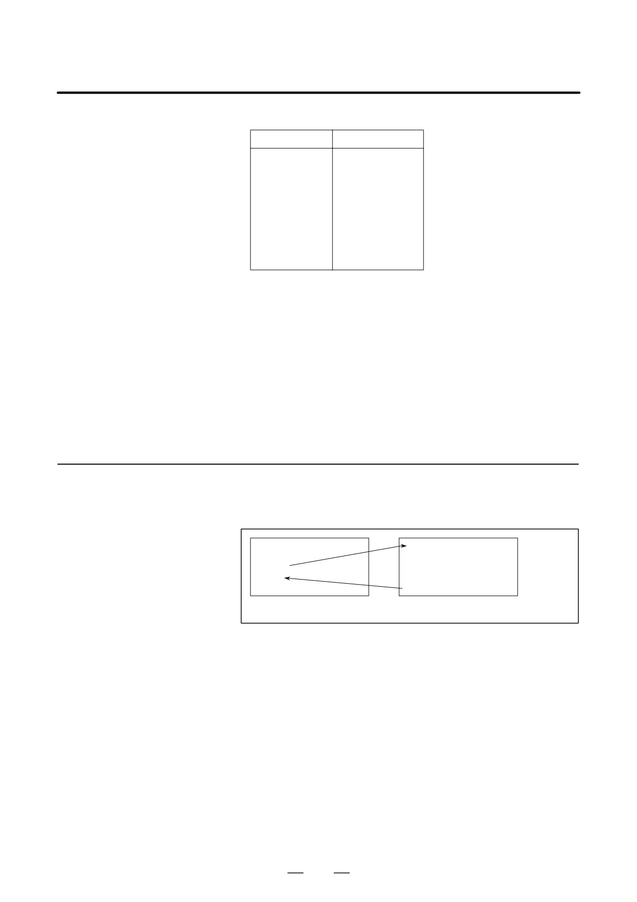
15. CUSTOM MACRO
PROGRAMMING
B-63534EN/02
D Correspondence
between parameter
Program number
Parameter number
numbers and program
O9001
6071
numbers
O9002
6072
O9003
6073
O9004
6074
O9005
6075
O9006
6076
O9007
6077
O9008
6078
O9009
6079
D Repetition
As with a simple call, a number of repetitions from 1 to 9999 can be
specified at address L.
D Argument specification
Argument specification is not allowed.
D M code
An M code in a macro program that has been called is treated as an
ordinary M code.
Limitations
In a macro called with a G code or in a program called with an M or T code,
no subprograms can be called using an M code. An M code in such a
macro or program is treated as an ordinary M code.
By enabling subprograms (macro program) to be called with a T code in
15.6.6
a parameter, a macro program can be called each time the T code is
Subprogram Calls
specified in the machining program.
Using a T Code
O0001 ;
O9000 ;
:
:
T23 ;
:
:
:
M30 ;
M99 ;
Bit 5 of parameter 6001 = 1
Explanations
D Call
By setting bit 5 of parameter TCS No.6001 to 1, the macro program
O9000 can be called when a T code is specified in the machining program.
A T code specified in a machining program is assigned to common
variable #149.
Limitations
In a macro called with a G code or in a program called with an M or T code,
no subprograms can be called using a T code. A T code in such a macro
or program is treated as an ordinary T code.
426

PROGRAMMING
15. CUSTOM MACRO
B-63534EN/02
15.6.7
By using the subprogram call function that uses M codes, the cumulative
usage time of each tool is measured.
Sample Program
Conditions
S The cumulative usage time of each of tools T01 to T05 is measured.
No measurement is made for tools with numbers greater than T05.
S The following variables are used to store the tool numbers and
measured times:
#501
Cumulative usage time of tool number 1
#502
Cumulative usage time of tool number 2
#503
Cumulative usage time of tool number 3
#504
Cumulative usage time of tool number 4
#505
Cumulative usage time of tool number 5
S Usage time starts being counted when the M03 command is specified
and stops when M05 is specified. System variable #3002 is used to
measure the time during which the cycle start lamp is on. The time
during which the machine is stopped by feed hold and single block
stop operation is not counted, but the time used to change tools and
pallets is included.
Operation check
D Parameter setting
Set 3 in parameter No.6071, and set 05 in parameter No.6072.
D Variable value setting
Set 0 in variables #501 to #505.
D Program that calls a
O0001;
macro program
T01 M06;
M03;
M05;
Changes #501.
T02 M06;
M03;
M05;
Changes #502.
T03 M06;
M03;
M05;
Changes #503.
T04 M06;
M03;
M05;
Changes #504.
T05 M06;
M03;
M05;
Changes #505.
M30;
427
15. CUSTOM MACRO
PROGRAMMING
B-63534EN/02
Macro program
O9001(M03);
Macro to start counting
(program called)
M01;
IF[#4120 EQ 0]GOTO 9;
No tool specified
IF[#4120 GT 5]GOTO 9;
Out-of-range tool number
#3002=0;
Clears the timer.
N9 M03;
Rotates the spindle in the forward
. . . . . . . . . . . . . . . . . . . . . . . . . . . . . . . . . direction.
M99;
O9002(M05);
Macro to end counting
M01;
IF[#4120 EQ 0]GOTO 9;
No tool specified
IF[#4120 GT 5]GOTO 9;
Out-of-range tool number
#[500+#4120]=#3002+#[500+#4120]; Calculates cumulative time.
N9 M05;
Stops the spindle.
M99;
428
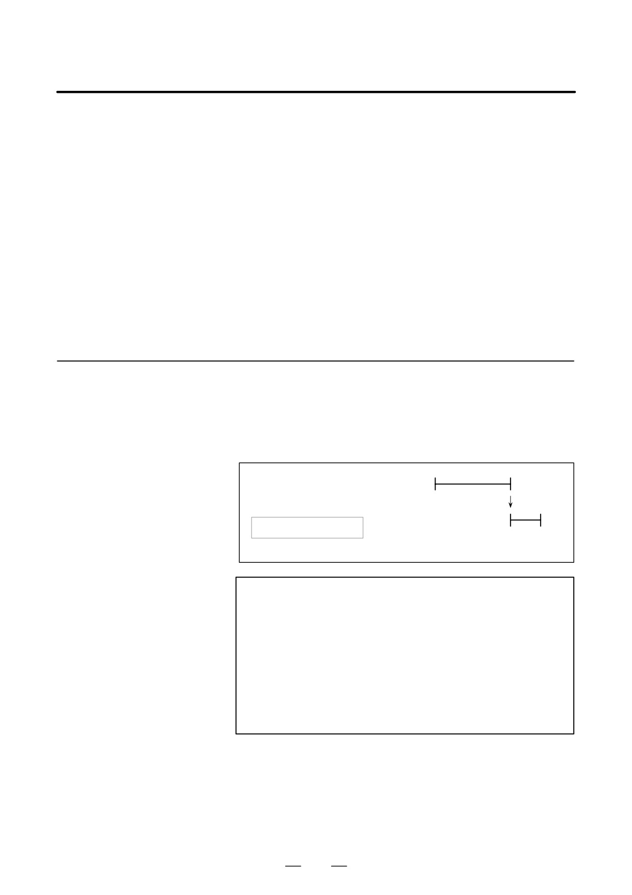
PROGRAMMING
15. CUSTOM MACRO
B-63534EN/02
For smooth machining, the CNC prereads the NC statement to be
15.7
performed next. This operation is referred to as buffering. During AI
PROCESSING
contour control mode or AI nano contour control mode, the CNC prereads
MACRO
not only the next block but also the multiple blocks. And in the cutter
compensation mode (G41, G42), the CNC prereads the NC statements
STATEMENTS
two or three blocks ahead to find intersections even if the CNC is not in
AI contour control mode nor AI nano contour control mode. Macro
statements for arithmetic expressions and conditional branches are
processed as soon as they are read into the buffer. Therefore, the timing
of the macro statement execution is not always the specified order.
At the blocks containing M00, M01, M02 or M30, blocks containing
M-codes for which buffering is suppressed by setting parameter
(No.3411-3432), and blocks containing prevention buffering G codes
such as G53, the CNC stops to preread the NC statement after that. Then,
the stop of the macro statement execution is guaranteed until such M
codes or G codes complete its execution.
15.7.1
Details of NC
Statements and Macro
Statements Execution
D When the next block is
not buffered
> N1 G31 X100.0 ;
N1
(M codes that are not
NC statement
N2 #100=1
buffered, G53, G31, etc.)
execution
:
N2
Macro statement execution
> :Block being executed
Buffer
NOTE
In case that you need to execute the macro statement after
completing the block just before the macro statement,
specify M code or G code that are not buffered just before
the macro statement. Specially, in case of reading / writing
the system variables to control signals, coordinates, offset
value, etc., it may different system variable data by the
timing of the NC statement execution. To avoid this
phenomenon, specify such M codes or G codes before the
macro statement, if necessary.
429