FANUC Series 16i/160i/160is-MB, Series 18i/180i/180is-MB5, Series 18i/180i/180is-MB. Operator's Manual - page 14
14. COMPENSATION FUNCTION
PROGRAMMING
B-63534EN/02
Examples
D Cutter compensation C
and coordinate system
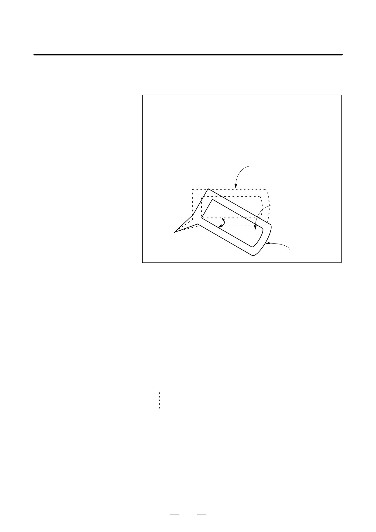
It is possible to specify G68 and G69 in cutter compensation C mode.
rotation
The rotation plane must coincide with the plane of cutter compensa-
tion C.
N1 G92 X0 Y0 G69 G01 ;
N2 G42 G90 X1000 Y1000 F1000 D01 ;
N3 G68 R*30000 ;
N4 G91 X2000 ;
N5 G03 Y1000 R1000 J500 ;
N6 G01 X*2000 ;
N7 Y*1000 ;
Programmed shape before
N8 G69 G40 G90 X0 Y0 M30 ;
coordinate system rotation
Programmed shape
after coordinate
system rotation
30°
(0, 0)
Tool path
Fig. 14.10 (d) Cutter compensation C and coordinate system rotation
D Scaling and coordinate
If a coordinate system rotation command is executed in the scaling mode
system rotation
(G51 mode), the coordinate value (α,β,) of the rotation center will also be
scaled, but not the rotation angle (R). When a move command is issued,
the scaling is applied first and then the coordinates are rotated.
A coordinate system rotation command (G68) should not be issued in
cutter compensation C mode (G41, G42) on scaling mode (G51). The
coordinate system rotation command should always be specified prior to
setting the cutter compensation C mode.
1. When the system is not in cutter compensation mode C, specify the
commands in the following order :
G51 ; scaling mode start
G68 ; coordinate system rotation mode start
G69 ; coordinate system rotation mode cancel
G50 ; scaling mode cancel
370
B-63534EN/02
PROGRAMMING
14. COMPENSATION FUNCTION
2.
When the system is in cutter compensation model C, specify the
commands in the following order (Fig.14.10(e)) :
(cutter compensation C cancel)
G51 ; scaling mode start
G68 ; coordinate system rotation start
:
G41 ; cutter compensation C mode start
:
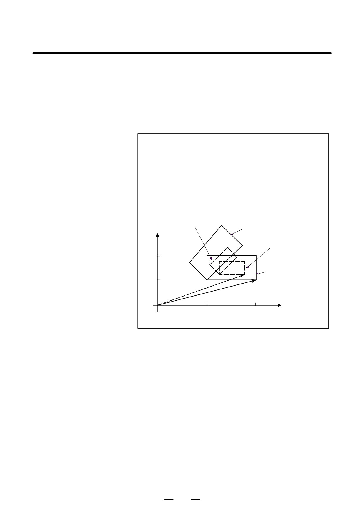
G92 X0 Y0 ;
G51 X300.0 Y150.0 P500 ;
G68 X200.0 Y100.0 R45.0 ;
G01 X400.0 Y100.0 ;
Y100.0 ;
X-200.0 ;
Y-100.0 ;
X200.0 ;
When scaling and coordinate
system rotation are applied
When only coordinate
Y
system rotation is applied
When only scaling
is applied
200.0
Cutting program
100.0
X
0
200.0
400.0
Fig. 14.10 (e) Scaling and coordinate system rotation
in cutter compensation C mode
371
14. COMPENSATION FUNCTION
PROGRAMMING
B-63534EN/02
D Repetitive commands for
It is possible to store one program as a subprogram and recall subprogram
coordinate system
by changing the angle.
rotation
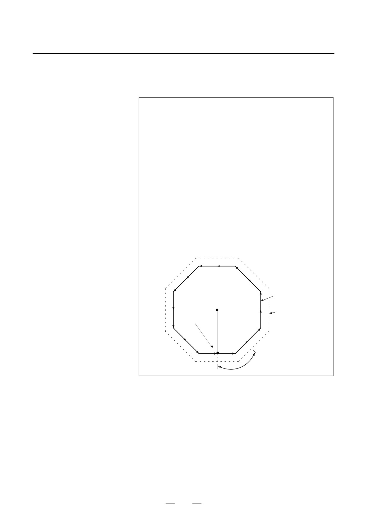
Sample program for when the RIN bit (bit 0 of parameter 5400) is set
to 1.
The specified angular displancement is treated as an absolute or
incremental value depending on the specified G code (G90 or G91).
G92 X0 Y0 G69 G17;
G01 F200 H01 ;
M98 P2100 ;
M98 P072200 ;
G00 G90 X0 Y0 M30 ;
O 2200 G68 X0 Y0 G91 R45.0 ;
G90 M98 P2100 ;
M99 ;
O 2100 G90 G01 G42 X0 Y-10.0 ;
X4.142 ;
X7.071 Y-7.071 ;
G40 ;
M99 ;
Programmed path
(0, 0)
When offset is
applied
(0, -10.0)
Subprogram
Fig. 14.10 (f) Coordinate system rotation command
372
B-63534EN/02
PROGRAMMING
14. COMPENSATION FUNCTION
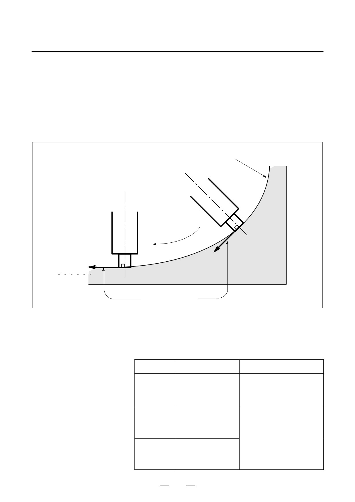
When a tool with a rotation axis (C-axis) is moved in the XY plane during
14.11
cutting, the normal direction control function can control the tool so that
NORMAL DIRECTION
the C-axis is always perpendicular to the tool path (Fig. 14.11 (a)).
CONTROL
(G40.1, G41.1, G42.1
OR G150, G151,
G152)
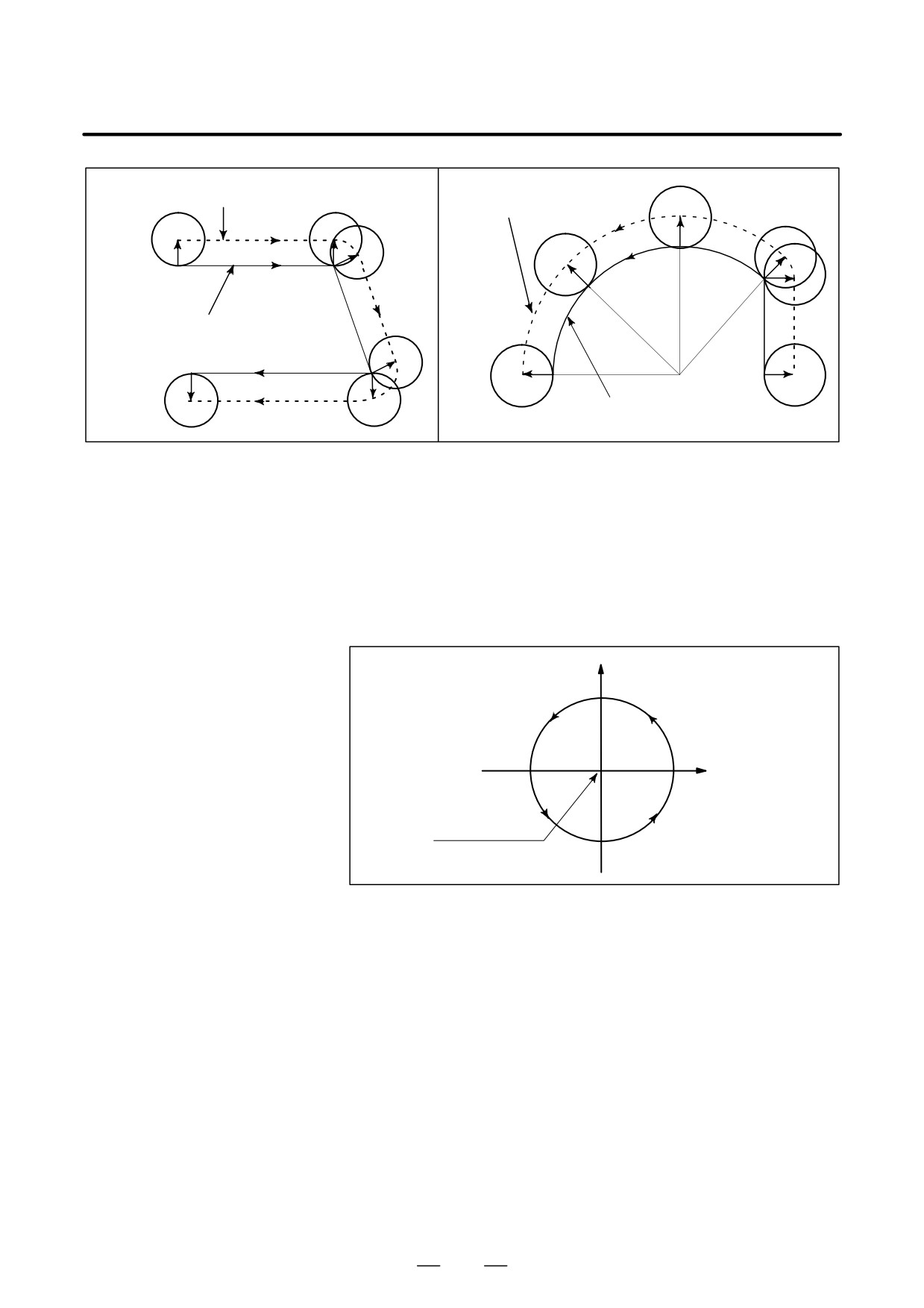
Programmed tool path
C-axis
C-axis
Tool
Tool
Normal direction (in
which the tool moves)
Fig. 14.11 (a) Sample Movement of the tool
Format
G code
Function
Explanation
If the workpiece is to the right of the
Normal direction
tool path looking toward the direc-
G41.1 or G151
control left
tion in which the tool advances,
the normal direction control left
(G41.1 or G151) function is speci-
fied.
Normal direction
After G41.1 (or G151) or G42.1 (or
G42.1 or G152
control right
G152) is specified, the normal
direction control function is en-
abled
(normal direction control
mode).
Normal direction
When G40.1 (or G150) is speci-
G40.1 or G150
control cancel
fied, the normal direction control
mode is canceled.
373
14. COMPENSATION FUNCTION
PROGRAMMING
B-63534EN/02
Cutter center path
Cutter center path
Programmed path
Center of the arc
Programmed path
Fig. 14.11 (b) Normal direction control left (G41.1)
Fig. 14.11 (c) Normal direction control right (G42.1)
Explanations
D Angle of the C axis
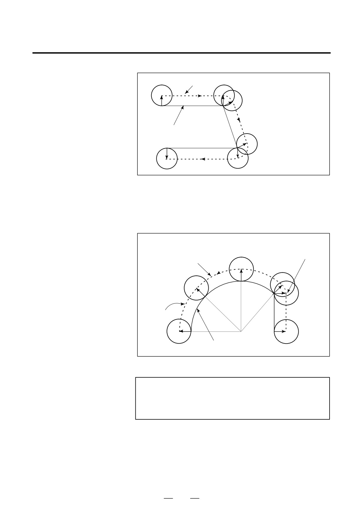
When viewed from the center of rotation around the C-axis, the angular
displacement about the C-axis is determined as shown in Fig. 14.11 (d).
The positive side of the X-axis is assumed to be 0 , the positive side of
the Y-axis is 90°, the negative side of the X-axis is 180°, and the negative
side of the Y-axis is 270°.
+Y
90°
+X
180°
0°
Center of rotation
270°
Fig. 14.11 (d) Angle of the C axis
D Normal direction control
When the cancel mode is switched to the normal direction control mode,
of the C axis
the C-axis becomes perpendicular to the tool path at the beginning of the
block containing G41.1 or G42.1.
In the interface between blocks in the normal direction control mode, a
command to move the tool is automatically inserted so that the C-axis
becomes perpendicular to the tool path at the beginning of each block.
The tool is first oriented so that the C-axis becomes perpendicular to the
tool path specified by the move command, then it is moved along the X-
and Y axes.
In the cutter compensation mode, the tool is oriented so that the C-axis
becomes perpendicular to the tool path created after compensation.
In single-block operation, the tool is not stopped between a command for
rotation of the tool and a command for movement along the X- and
Y-axes. A single-block stop always occurs after the tool is moved along
the X- and Y-axes.
374
B-63534EN/02
PROGRAMMING
14. COMPENSATION FUNCTION
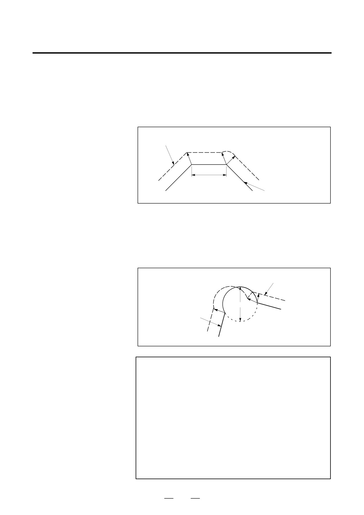
Cutter center path
S
N1
S : Single block stop point
Programmed path
N2
S
N3
S
Fig. 14.11 (e) Point at which a Single-Block Stop Occurs in the
Normal Direction Control Mode
Before circular interpolation is started, the C-axis is rotated so that the
C-axis becomes normal to the arc at the start point. During circular
interpolation, the tool is controlled so that the C-axis is always
perpendicular to the tool path determined by circular interpolation.
The tool is controlled so that the C-
A rotation command is inserted
axis
so that the C-axis becomes nor-
is always normal to the tool path de-
mal to the arc at the start point.
termined by circular interpolation.
Tool center path
Center of the arc
Programmed path
Fig. 14.11 (f) Normal direction control of the circular interpolation
NOTE
During normal direction control, the C axis always rotates
through an angle less than 180 deg. I.e., it rotates in
whichever direction provides the shorter route.
375
14. COMPENSATION FUNCTION
PROGRAMMING
B-63534EN/02
D C axis feedrate
Movement of the tool inserted at the beginning of each block is executed
at the feedrate set in parameter 5481. If dry run mode is on at that time,
the dry run feedrate is applied. If the tool is to be moved along the X-and
Y-axes in rapid traverse (G00) mode, the rapid traverse feedrate is
applied.
The federate of the C axis during circular interpolation is defined by the
following formula.
Amount of movement of the C axis (deg)
F×
(deg/min)
Length of arc (mm or inch)
F : Federate (mm/min or inch/min) specified by the corresponding
block of the arc
Amount of movement of the C axis : The difference in angles at the
beginning and the end of the
block.
NOTE
If the federate of the C axis exceeds the maximum cutting
speed of the C axis specified to parameter No. 1422, the
federate of each of the other axes is clamped to keep the
federate of the C axis below the maximum cutting speed of
the C axis.
D Normal direction control
A C-axis to which normal-direction control is applied can be assigned
axis
to any axis with parameter No. 5480.
D Angle for which figure
When the rotation angle to be inserted, calculated by normal-direction
insertion is ignored
control, is smaller than the value set with parameter No. 5482, the
corresponding rotation block is not inserted for the axis to which
normal-direction control is applied. This ignored rotation angle is added
to the next rotation angle to be inserted, the total angle being subject to
the same check at the next block.
If an angle of 360 degrees or more is specified, the corresponding rotation
block is not inserted.
If an angle of 180 degrees or more is specified in a block other than that
for circular interpolation with a C-axis rotation angle of 180 degrees or
more, the corresponding rotation block is not inserted.
376
B-63534EN/02
PROGRAMMING
14. COMPENSATION FUNCTION
D Movement for which arc
Specify the maximum distance for which machining is performed with
insertion is ignored
the same normal direction as that of the preceding block.
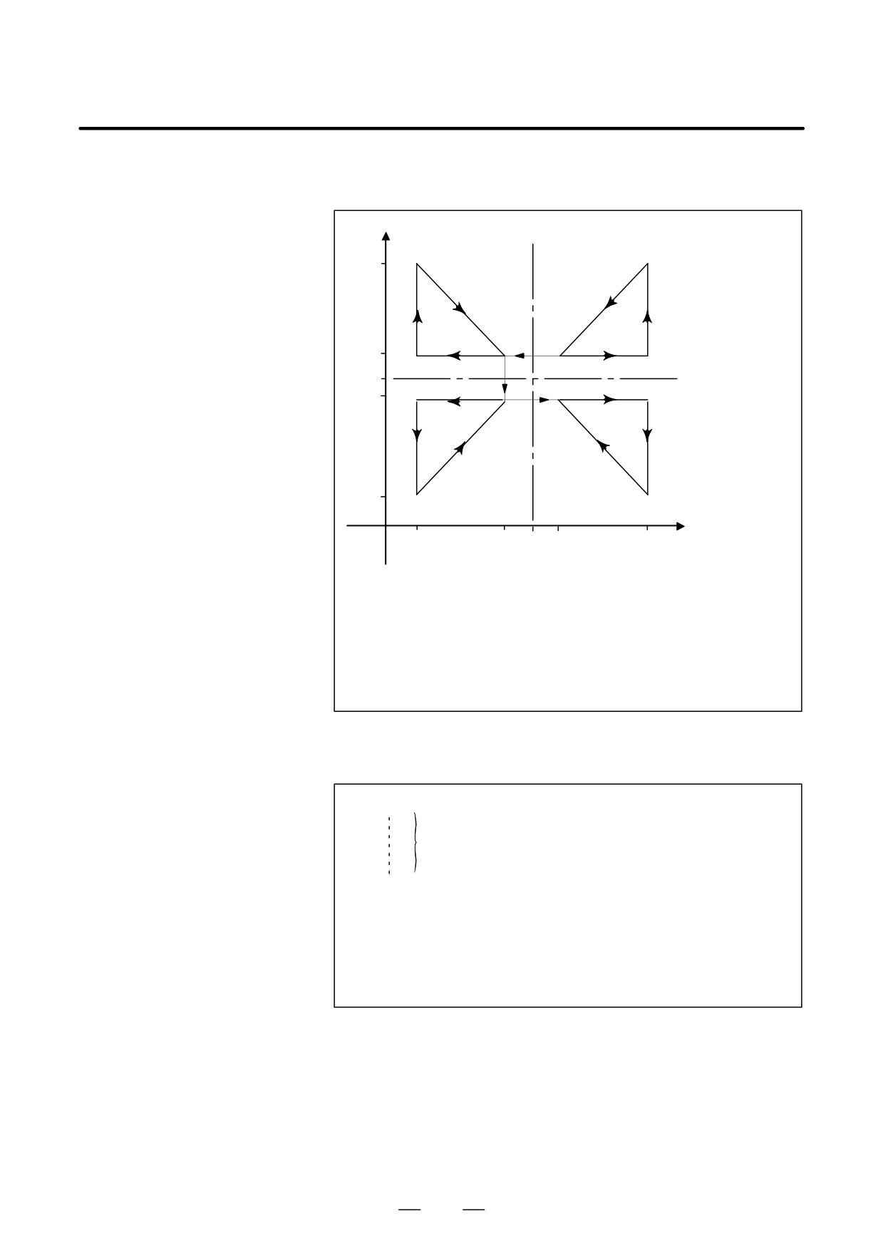
D Linear movement
When distance N2, shown below, is smaller than the set value,
machining for block N2 is performed using the same direction as that
for block N1.
Tool-center path
N2
N3
N1
Distance
Programmed path
D Circular movement
When the diameter of block N2, shown below, is smaller than the set
value, machining for block N2 is performed using the same normal
direction as that for block N1. The orientation of the axis to which
normal-direction control is applied, relative to the normal direction of
block N2, does not change as machining proceeds along the arc.
Tool-center path
N2
N3
Diameter
Programmed path
N1
NOTE
1
Do not specify any command to the C axis during normal
direction control. Any command specified at this time is
ignored.
2
Before processing starts, it is necessary to correlate the
workpiece coordinate of the C axis with the actual position
of the C axis on the machine using the coordinate system
setting (G92) or the like.
3
The helical cutting option is required to use this function.
Helical cutting cannot be specified in the normal direction
control mode.
4
Normal direction control cannot be performed by the G53
move command.
5
The C-axis must be a rotation axis.
377
14. COMPENSATION FUNCTION
PROGRAMMING
B-63534EN/02
A mirror image of a programmed command can be produced with respect
14.12
to a programmed axis of symmetry (Fig. 14.12 (a)).
PROGRAMMABLE
MIRROR IMAGE
Y
Axis of symmetry (X=50)
(2)
(1)
(G50.1, G51.1)
100
60
Axis of symmetry
50
(Y=50)
40
0
(3)
(4)
0
40
50
60
100
X
(1) Original image of a programmed command
(2) Image symmetrical about a line parallel to the Y-axis and crossing
the X-axis at 50
(3) Image symmetrical about point (50, 50)
(4) Image symmetrical about a line parallel to the X-axis and crossing
the Y-axis at 50
Fig. 14.12 (a) Programmable Mirror image
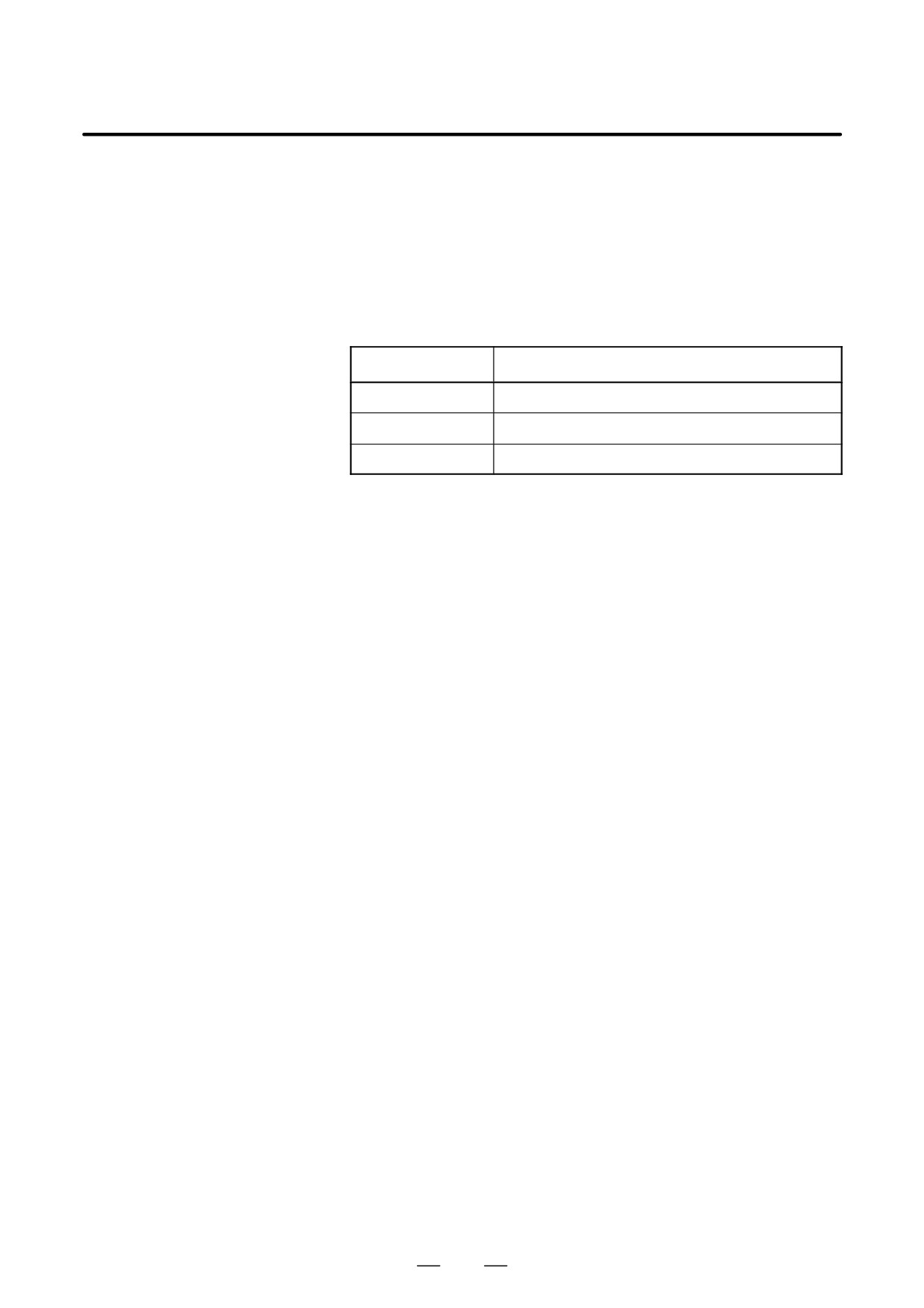
Format
G51.1IP_ ; Setting a programmable image
A mirror image of a command specified in these
blocks is produced with respect to the axis of
symmetry specified by G51.1
IP
_;.
G50.1
_ ; Canceling a programmable mirror image
IP
IP_ : Point (position) and axis of symmetry for producing
a mirror image when specified with G51.1.
Axis of symmetry for producing a mirror image when
specified with G50.1. Point of symmetry is not speci-
fied.
378
B-63534EN/02
PROGRAMMING
14. COMPENSATION FUNCTION
Explanations
D Mirror image by setting
If the programmable mirror image function is specified when the
command for producing a mirror image is also selected by a CNC external
switch or CNC setting (see III-4.9), the programmable mirror image
function is executed first.
D Mirror image on a single
Applying a mirror image to one of the axes on a specified plane changes
axis in a specified plane
the following commands as follows :
Command
Explanation
Circular command
G02 and G03 are interchanged.
Cutter compensation
G41 and G42 are interchanged.
Coordinate rotation
CW and CCW (directions of rotation) are interchanged.
Limitations
D Scaling/coordinate
Processing proceeds from program mirror image to scaling and
system rotation
coordinate rotation in the stated order. The commands should be specified
in this order, and, for cancellation, in the reverse order. Do not specify
G50.1 or G51.1 during scaling or coordinate rotation mode.
D Commands related to
In programmable mirror image mode, G codes related to reference
reference position return
position return (G27, G28, G29, G30, etc.) and those for changing the
and coordinate system
coordinate system (G52 to G59, G92, etc.) must not be specified. If any
of these G codes is necessary, specify it only after canceling the
programmable mirror image mode.
379
14. COMPENSATION FUNCTION
PROGRAMMING
B-63534EN/02
14.13
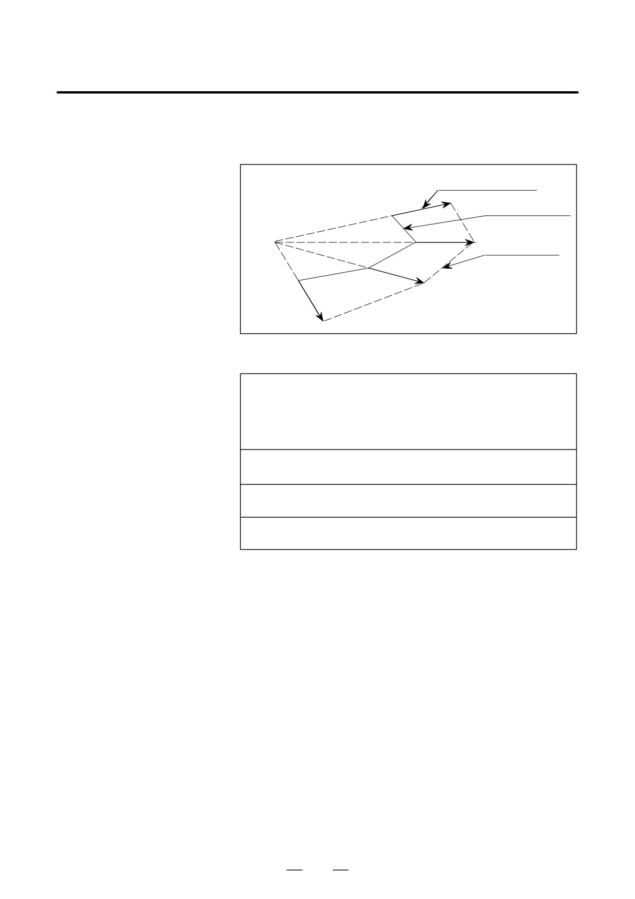
The grinding wheel compensation function creates a compensation vector
by extending the line between the specified compensation center and the
GRINDING WHEEL
specified end point, on the specified compensation plane.
WEAR
COMPENSATION
Compensation vector
Programmed path
Compensation
center
Tool center path
Format
D Selecting the
G41 Pn (n=1, 2, 3);
compensation center
G41 P1; Select the first compensation center
G41 P2; Select the second compensation center
G41 P3; Select the third compensation center
D Start-up
D_; D code other than D0
D Canceling
D0;
compensation mode
G40;
D Holding the
compensation vector
Explanations
D Setting and selecting the
Three compensation centers can be specified by specifying their center
compensation center
coordinates with parameters No. 5081 to 5086. The G41Pn (n = 1, 2, or
3) command is used to specify which compensation center is to be used.
G41 P1 ;
Select the first compensation center.
G41 P2 ;
Select the second compensation center.
G41 P3 ;
Select the third compensation center.
When selecting the compensation center, specify P1, P2, or P3 at the same
time with G41. If G41 has been specified without a P command or with
a P command other than P1, P2, and P3, P/S alarm 5069 is issued.
When specifying the compensation center with parameters, use the
workpiece coordinates.
D Start-up
To enter compensation mode, specify the compensation center, then
specify a D code other than D0. A compensation vector is created and the
tool is accordingly moved, even if the block in which the D code has been
specified does not contain a move command.
380
B-63534EN/02
PROGRAMMING
14. COMPENSATION FUNCTION
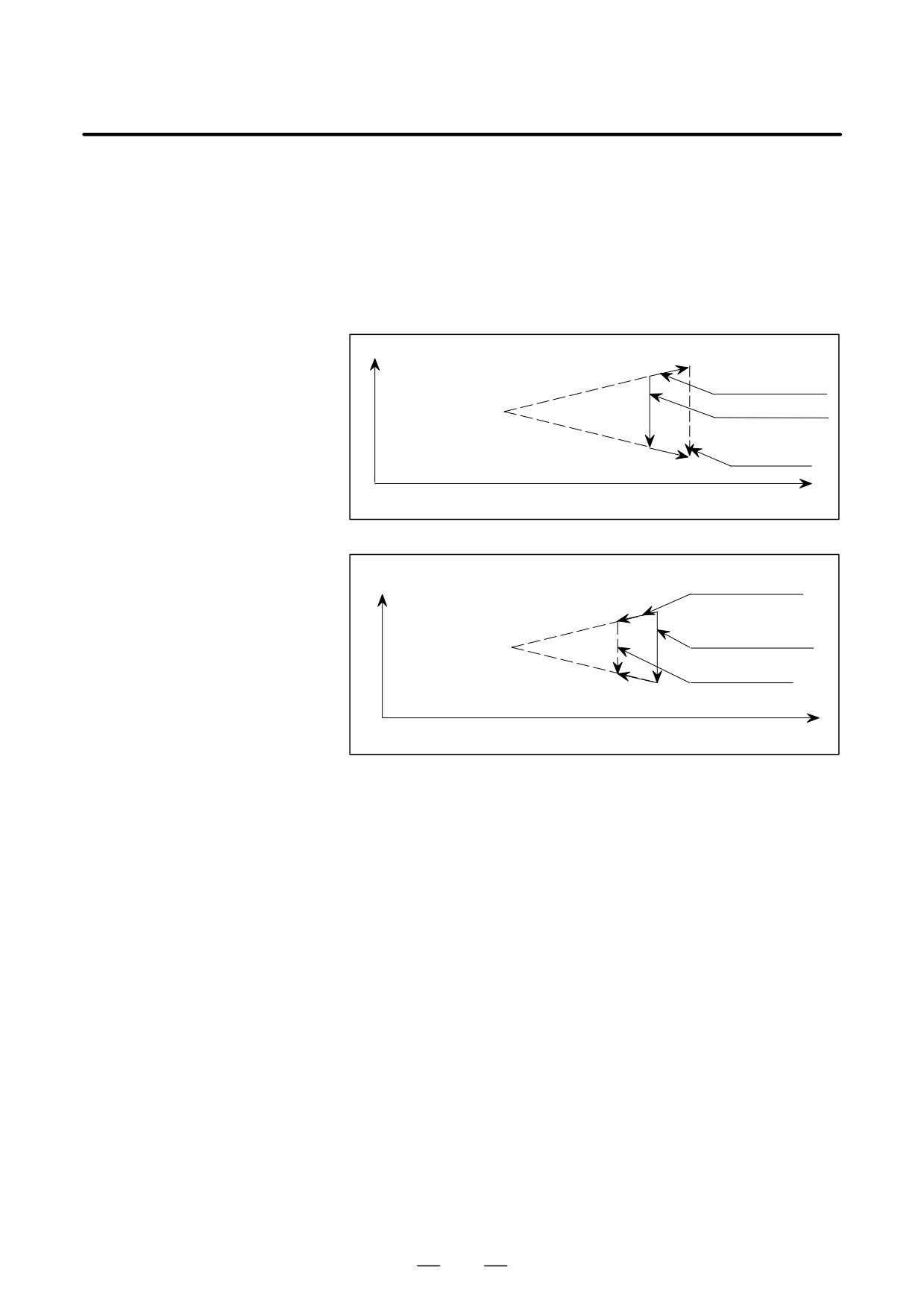
A compensation vector is created by extending the line between the
D Compensation vector
compensation center and the specified end point. The length of the
compensation vector equals to the offset value corresponding to the offset
number specified with the D code.
When the offset value is positive, the compensation vector is added to the
specified end point. When the offset value is negative, the compensation
vector is subtracted from the specified end point.
+
Z
Compensation
vector (+)
Compensation
center
Programmed path
Tool center
path
Y+
Offset value (+)
Compensation
vector (-)
+
Z
Compensation
Programmed path
center
Tool center path
Y+
Offset value (-)
D Canceling compensation
Specifying D0 cancels compensation mode, thus disabling the creation of
mode
a compensation vector.
D Holding the
Specifying G40 selects a mode for holding the current compensation
compensation vector
vector. In this mode, the specified end point is shifted by the same vector
length until a different compensation mode is specified.
Specifying D0 in compensation vector hold mode clears the
compensation vector and cancels compensation mode.
381
14. COMPENSATION FUNCTION
PROGRAMMING
B-63534EN/02
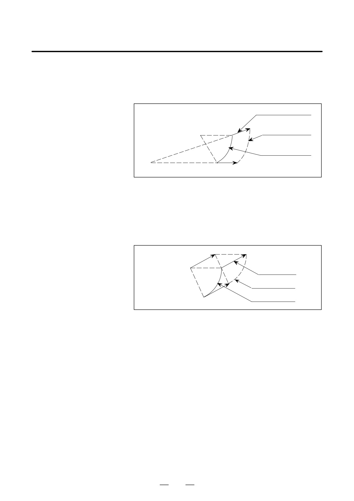
D Circular and helical
Grinding wheel wear compensation can also be applied to circular
interpolation
interpolation and helical interpolation. If the radius at the start point
differs from that at the end point, the figure does not become an arc; it
becomes a helix.
Compensation vector
Arc center
Tool center path
Programmed path
Compensation center
The compensated values are still subject to arc radius error limit
(parameter No. 3410) check.
D Circular interpolation in
Specifying an arc command in G40 mode causes the arc center to be
G40 mode
shifted by the vector length, thus causing the figure to become an arc, not
a helix.
Programmed
arc center
Held vector
Tool center path
Programmed path
D Exponential interpolation
Grinding wheel wear compensation can also be applied to exponential
interpolation.
Exponential interpolation is performed for the
compensated positions.
D Compensation plane and
A compensation vector is created only on the plane (compensation plane)
plane selection using
corresponding to the axes specified with parameters No. 5071 and 5072
G17/G18/G19
(compensation axes).
In compensation mode (including compensation vector hold mode), a
compensation vector is always created on the compensation plane
specified with parameters (No. 5071 and 5072), regardless of the plane
selected with the G17, G18, or G19 command. For example,
compensation can be performed using the YZ plane as the compensation
plane while circular interpolation is performed on the XY plane (G17).
If a move command has been specified for either compensation axis, in
compensation mode, the compensation vector component of the other
axis may be changed during compensation vector creation, thus causing
the tool to also move along that axis.
382
B-63534EN/02
PROGRAMMING
14. COMPENSATION FUNCTION
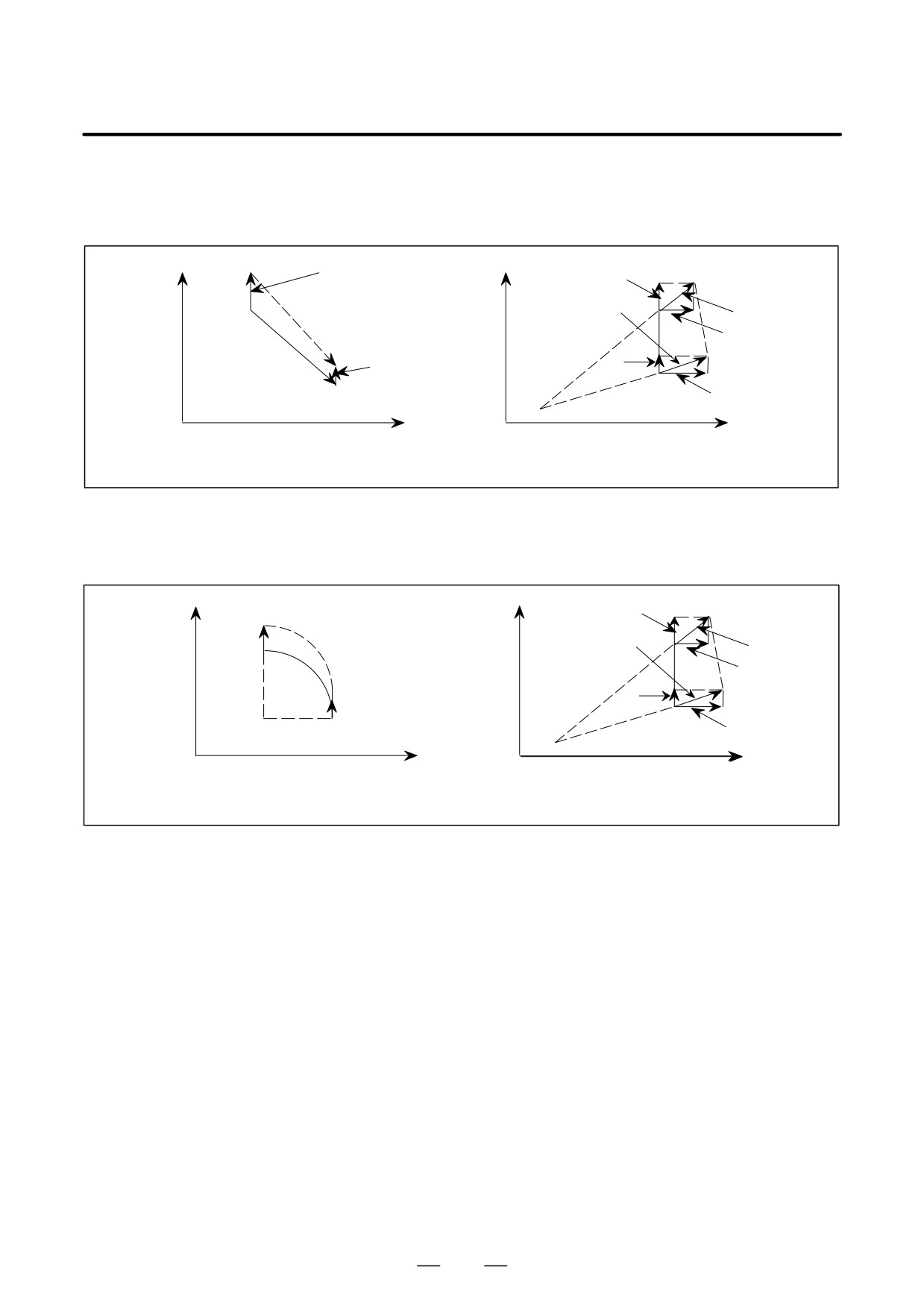
(Example 1)
When the compensation axes are the Y- and Z-axes and
linear interpolation is performed for the X- and Y-axes
Programmed path: a → b, compensated path: a’ → b’
+
a’
Vay
+
a’
Vay
Y
Y
Vb
a
a
Va
Vaz
Compensation
b’
center
b’
Vby
Vby
b
b
Vbz
X+
Z+
Paths on the XY plane
Paths on the YZ plane
(Example 2)
When the compensation axes are the Y- and Z-axes and
circular interpolation is performed for the X- and Y-axes
Programmed path: a → b, compensated path: a’ → b’
+
a’
+
Vay
a’
Y
Y
Vb
a
Va
a
Vaz
Compensation
b’
center
b’
Vby
b
b
Arc center
Vbz
Z+
X+
Paths on the YZ plane
Paths on the XY plane
D Compensation cancel
Compensation cancel mode is selected immediately after power-on or
mode
reset.
D Changing the coordinate
Before attempting to change the coordinate system, cancel compensation
system
mode.
D Reference position
Before attempting to return to the reference point (G28 or G30), cancel
return (G28, G30)
compensation mode.
Limitations
D Changing the
The compensation axes can be changed only in compensation cancel
compensation axes
mode.
D Relationship with other
Cutter compensation and three-dimensional tool compensation cannot be
offset functions
used when grinding wheel wear compensation is enabled on the system.
The tool length offset and tool position offset functions can be used with
grinding wheel wear compensation.
D Relationship with the
The coordinates of the compensation center are not subject to
coordinate change
programmable mirror image, scaling, or coordinate rotation.
function
383
14. COMPENSATION FUNCTION
PROGRAMMING
B-63534EN/02
14.14
The rotary table dynamic fixture offset function saves the operator the
trouble of re-setting the workpiece coordinate system when the rotary
ROTARY TABLE
table rotates before cutting is started. With this function the operator
DYNAMIC FIXTURE
simply sets the position of a workpiece placed at a certain position on the
OFFSET
rotary table as a reference fixture offset. If the rotary table rotates, the
system automatically obtains a current fixture offset from the angular
displacement of the rotary table and creates a suitable workpiece
coordinate system. After the reference fixture offset is set, the workpiece
coordinate system is prepared dynamically, wherever the rotary table is
located.
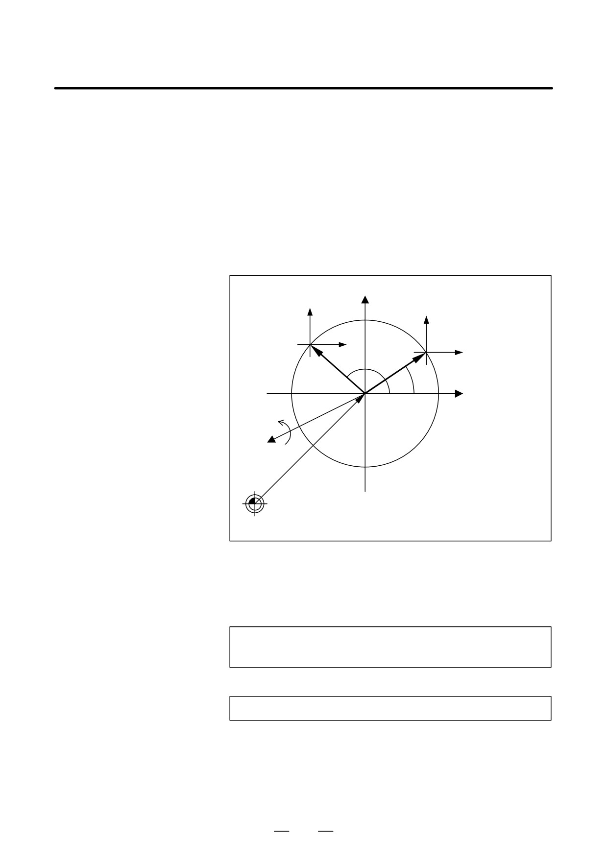
The zero point of the workpiece coordinate system is obtained by adding
the fixture offset to the offset from the workpiece reference point.
Y
Y
Y
X
X
F0
F
θ
θ0
X
Rotation axis
center
C
Z
W
W
: Workpiece origin offset value
θ0
: Reference angle
F0
: Reference fixture offset value
Machine coordinate
θ
: Rotation axis angle
system origin
F
: Fixture offset value
Fig.14.14 (a) Fixture offset
Format
D Fixture offset command
G54.2 Pn ;
n : Reference fixture offset value number (1 to 8)
D Fixture offset cancel
command
G54.2 P0 ;
384
B-63534EN/02
PROGRAMMING
14. COMPENSATION FUNCTION
Explanations
D When a move command
When a command to move the tool about a rotation axis involved with a
is specified for a rotation
fixture offset is specified in the G54.2 mode, the coordinates about the
axis in G54.2 mode
rotation axis at the end of the block are used to calculate a vector. The tool
is moved to the specified position on the workpiece coordinate system
that is indicated by the vector.
D Operation at reset
Whether to cancel the fixture offset at a reset depends on the settings of
bit 6 (CLR) of parameter No. 3402 and of bit 7 (C23) of parameter No.
3408.
When CLR is set to 0 or CLR and C23 are set to 1, the vector before the
reset is saved.
When CLR is set to 1 and C23 is set to 0, the vector is cleared. The
machine does not move by the cleared vector regardless of the setting of
bit 0 (FTP) of parameter No. 7570, however.
D Data setting
(1) Setting a group of three parameters which specify one rotation axis
and two linear axes constituting the plane of rotation
(Parameter No.7580 to 7588)
In each group, specify the number of the rotation axis as the first
parameter and the numbers of the linear axes as the second and third
parameters. The rotation in the normal direction about the rotation
axis must agree with the rotation from the positive side of the linear
axis set as the second parameter to the positive side of the linear axis
set as the third parameter.
Example) Suppose that a machine has four axes, X, Y, Z, and C. The X-,
Y-, and Z-axes form a right-handed coordinate system. The
C-axis is a rotation axis. When viewed from the positive side
of the Z-axis, a rotation in the normal direction about the
C-axis is treated as the counterclockwise rotation around the
Z-axis.
For this machine, specify the parameters as follows :
First parameter
:
4 (C-axis)
Second parameter : 1 (X-axis)
Third parameter
:
2 (Y-axis)
Up to three groups of parameters can be set. In calculation of
the fixture offset, the data of the rotation axis specified in the
first group is calculated first. Then, the data of the second and
third groups are calculated.
If a machine has two or more rotation axes and the plane of
rotation depends on the rotation about another rotation axis,
the plane of rotation is set when the angular displacement
about the rotation axis is 0 .
(2) Setting the reference angle of the rotation axis and the corresponding
reference fixture offset
Set the reference angle of the rotation axis and the fixture offset that
corresponds to the reference angle.
385
14. COMPENSATION FUNCTION
PROGRAMMING
B-63534EN/02
Y
F
X
W
C
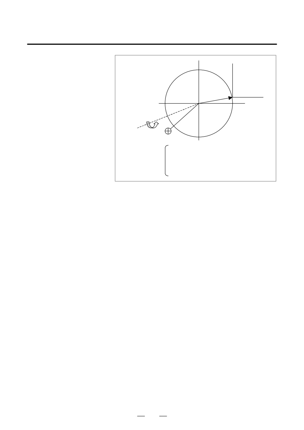
W: Workpiece origin offset value
F: Fixture offset corresponding to the
reference angle
Set the data on the fixture offset screen (See III-11.4). Eight groups
of data items can be specified.
(3) Setting a parameter for enabling or disabling the fixture offset of each
axis (bit 0 (FAX) of parameter 7575)
For the axis for which the fixture offset is enabled, set the parameter
to 1. This need not be specified for a rotation axis.
(4) Setting the type of fixture offset (bit 1 (FTP) of parameter 6004)
Specify whether to cause a movement according to the increment or
decrement of the fixture offset vector when the vector changes (when
G54.2 is specified or when a rotation axis movement occurs in the
G54.2 mode).
When 0 is set, the movement is made. (The current position on the
workpiece coordinate system does not change. The position on the
machine coordinate system changes.)
When 1 is set, the movement is not made. (The current position on
the workpiece coordinate system changes. The position on the
machine coordinate system does not change.)
D Inputting and outputting
The setting of a program and external data can be input and output as
the fixture offset
described below :
(1) Setting the reference fixture offset by G10
G10 L21 Pn IP ;
n : Number of fixture offset
IP : Reference fixture offset or reference angle of each axis
This command sets the reference fixture offset or reference angle in
a program.
When the command is executed in the G90 mode, the specified value
is set directly.
When the command is executed in the G91 mode, the specified value
plus a value set before the execution is set.
386
B-63534EN/02
PROGRAMMING
14. COMPENSATION FUNCTION
NOTE
The programmable data input function (G10) is required.
(2) Reading and writing the data by a system variable of a custom macro
System variable number = 5500 + 20:n + m
The following system variable number can be used to read and write
the reference fixture offset or reference angle. No data can be written
in the system variable area (5500 to 5508) with n = 0, however.
n : Fixture offset number (1 to 8)
When n is 0, the current offset is indicated.
m : Axis number (1 to number of controlled axes)
System variable 5500 can be used to read the selected offset number.
NOTE
The custom macro function is required.
(3) Reading and writing the data by the PMC window or open CNC
The window function can be used to read and write the custom macro
system variable with the same number as for (2).
NOTE
The NC window function and custom macro function are
required.
(4) Outputting the data to an external device
By selecting <PUNCH> on the fixture offset screen, the data can be
output to a Floppy Cassette, memory card or other external device via
RS-232C.
The data is output in the G10 form without a program number.
NOTE
The reader/punch interface function and programmable
data input function (G10) are required.
(5) Input from an external device
Register the data output in step (4) into the CNC memory as a
program and execute the program to input the data.
NOTE
The reader/punch interface function and programmable
data input function (G10) are required.
387
14. COMPENSATION FUNCTION
PROGRAMMING
B-63534EN/02
D Calculating the Fixture
Offset
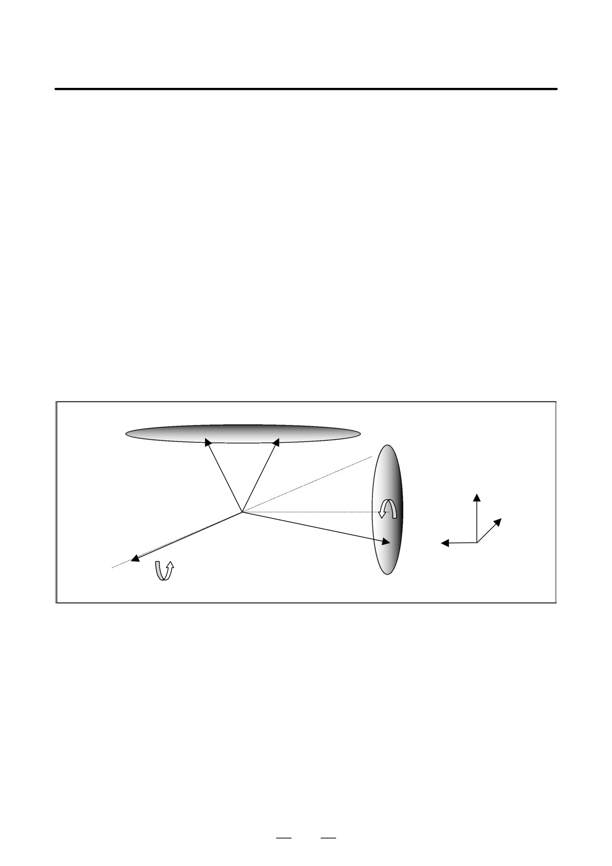
(1) Relationship between the rotation axis and linear axes
First group : 5(B-axis), 1(X-axis) , 3(Z-axis)
Second group
: 4(A-axis) , 3(Z-axis) , 2(Y-axis)
Third group
: 0, 0, 0
(2) Reference angle and reference fixture offset
X : F0X
Y : F0Y
Z : F0Z
A : φ0
B : θ0
The calculation method is shown below when data is set as above:
O
: Rotary table center
W : Workpiece origin offset value
F0
: Fixture offset value when A = φ0 and B = θ0
FA
: Fixture offset value when A = 0 and B = 0
F1
: Fixture offset value when A = 0 and B = θ
F
: Fixture offset value when A = φ and B = θ
F1
F
Z
O
X
FA
F0
Y
A
FA =
(FAX, FAY, FAY)
F1 =
(F1X, F1Y, F1Z)
F
=
(FX, FY, FZ)
Then, the following expression is used for fixture offset calculation.
FAX +
* sin(* q0)
0
0
F0X
ȱcos(*q0)
0
ȳ
ȱ1
ȳȱ
ȳ
cos(f0)
* sin(f0)
F0Y
FAY +
0
1
0
0
ȧ
ȧ
ȧ
ȧ
FAZ +
0
* cos(* q0)
0
sin(f0)
cos(f0)
F0Z
Ȳsin(*q0)
ȴȲ
ȴȲ
ȴ
F1X +
F0X
0
* sin(q)
ȱ
ȳ
ȱcos(q)
ȳ
F1Y +
0
1
0
F0Y
ȧ
ȧ
ȧ
F1Z +
0
cos(q)
F0Z
Ȳsin(q)
ȴȲ
ȴ
FX +
0
0
ȱ
1
ȳȱF1X
ȳ
FY +
0
cos(* f)
* sin(* f0)
F1Y
ȧ
ȧ
ȧ
FZ +
0
sin(* f)
cos(* f0)
F1Z
Ȳ
ȴȲ
ȴ
388
B-63534EN/02
PROGRAMMING
14. COMPENSATION FUNCTION
Limitation
D When data is modified in
In the G54.2 mode, a change made to the setting of parameter No. 7580
G54.2 mode
to 7588 or to the reference fixture offset becomes effective when the next
G54.2Pn is specified.
D Movement due to a
It depends on the current continuous-state code of the 01 group whether
fixture offset vector
a change in the fixture offset vector causes a movement. If the system is
change
in a mode other than the G00 or G01 mode (G02, G03, etc.), the
movement is made temporarily in the G01 mode.
D When a rotation axis is
When the automatic operation is stopped using the SBK stop function
manually adjusted
during the G54.2 mode and a manual movement is made about the
rotation axis, the fixture offset vector does not change. The vector is
calculated when a rotation axis command or G54.2 is specified for
automatic operation or MDI operation.
When manual intervention is performed in the manual absolute switch on
status and a rotation axis command is specified in the incremental (G91)
mode, however, the vector is calculated using the coordinates on which
the manual intervention is reflected. This operation is not a specification
of the FS15.
If the ABS bit (bit 3 of parameter 2409) is set to 0 or the G90 mode is
selected when N3 is specified, the coordinate of the C-axis is assumed to
be 40.0(30.0+10.0), which is the specified value, in calculation.
D When compensation is
In calculation of the fixture offset, the coordinate of the rotation axis on
applied to a rotation axis
the workpiece coordinate system is used. If a tool offset or another offset
is applied, the coordinate before the offset is used.
D Command for
If the following commands are specified for the rotation axis in the G54.2
suppressing fixture
mode, the fixture offset vector is not calculated :
offset calculation
Command related to the machine coordinate system : G53
Command specifying a change of the workpiece coordinate
system : G54 to G59, G54.1, G92, G52
Command specifying a return to the reference
position
: G27, G28, G29, G30, G30.1
D Rotation axis used for
The rotation axis used for polar coordinate interpolation (G12.1) cannot
fixture offset
be set as the rotation axis for the fixture offset.
D Rotation axis roll over
When using the rotary axis roll over function, always specify 360 degrees
for the amount of travel per revolution of the rotation axis.
D Functions that cannot be
In the G54.2 mode, the functions listed below cannot be specified.
specified
D Program restart function
D Mirror image function
D Scaling function
D Coordinate system rotation function
D High-speed contour control function and AI/AI-nano contour
control function
D Fugure copy function
389
14. COMPENSATION FUNCTION
PROGRAMMING
B-63534EN/02
Example
Parameter
Parameter 7580=4 (C-axis)
Parameter 7581=1 (X-axis)
Parameter 7582=2 (Y-axis)
Parameter 7583 to 7588=0
Parameter 7575#0(X)=1 (The offset is valid for the X-axis.)
7575#0(Y)=1 (The offset is valid for the Y-axis.)
7570#0=0 (When bit 0 of parameter 7570 is set to 1, the values in
square brackets ([ ]) are calculated.)
Data of fixture offset 1 (n = 1)
C= 180.0 (reference angle)
X= -10.0
Y= 0.0
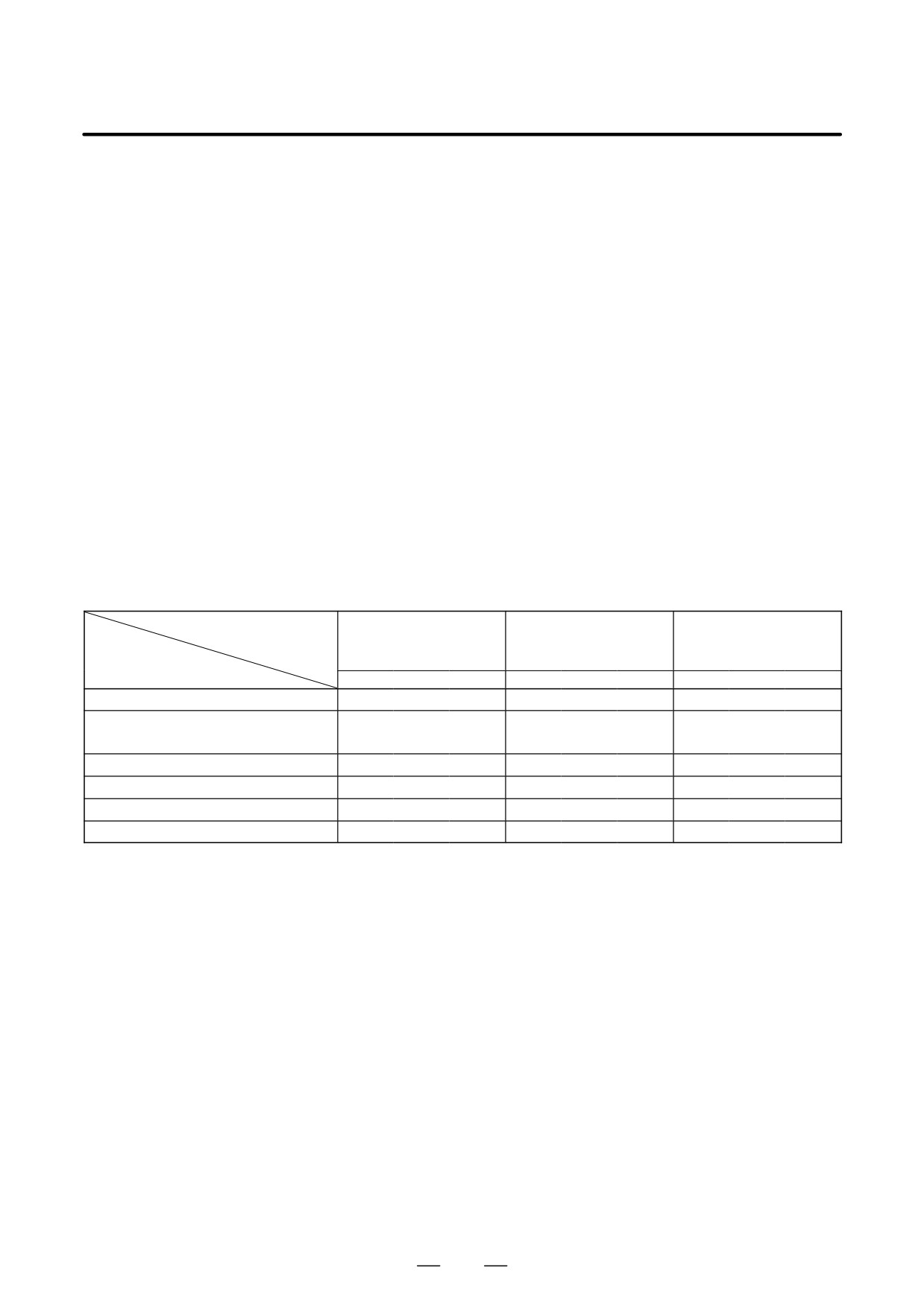
When these parameters and data are set, the machine operates as shown
below :
Table 14.14 Example of fixture offset
Coordinates
Position on the
Position on the
workpiece coordinate
machine coordinate
Fixture offset
system (ABSOLUTE)
system (MACHINE)
Program
X
Y
C
X
Y
C
X
Y
C
N1 G90 G00 X0 Y0 C90. ;
0.0
0.0
90.0
0.0
0.0
90.0
0.0
0.0
0.0
N2 G54.2 P1 ;
0.0
0.0
90.0
0.0
10.0
90.0
0.0
10.0
0.0
[0.0
-10.0
90.0]
[0.0
0.0
90.0]
[0.0
10.0
0.0]
N3 G01 X10. Y2. F100. ;
10.0
2.0
90.0
10.0
12.0
90.0
0.0
10.0
0.0
N4 G02 X2. Y10. R10. ;
2.0
10.0
90.0
2.0
20.0
90.0
0.0
10.0
0.0
N5 G01 X0 Y0 ;
0.0
0.0
90.0
0.0
10.0
90.0
0.0
10.0
0.0
:
The values enclosed in brackets ([ ]) apply when bit 0 (FTP) of parameter
No. 7570 is set to 1.
390
B-63534EN/02
PROGRAMMING
14. COMPENSATION FUNCTION
Y
C
C=90_
N4
C=180k
N5
N3
N2
[N3]
X
Zero POINT of the machine
coordinate system
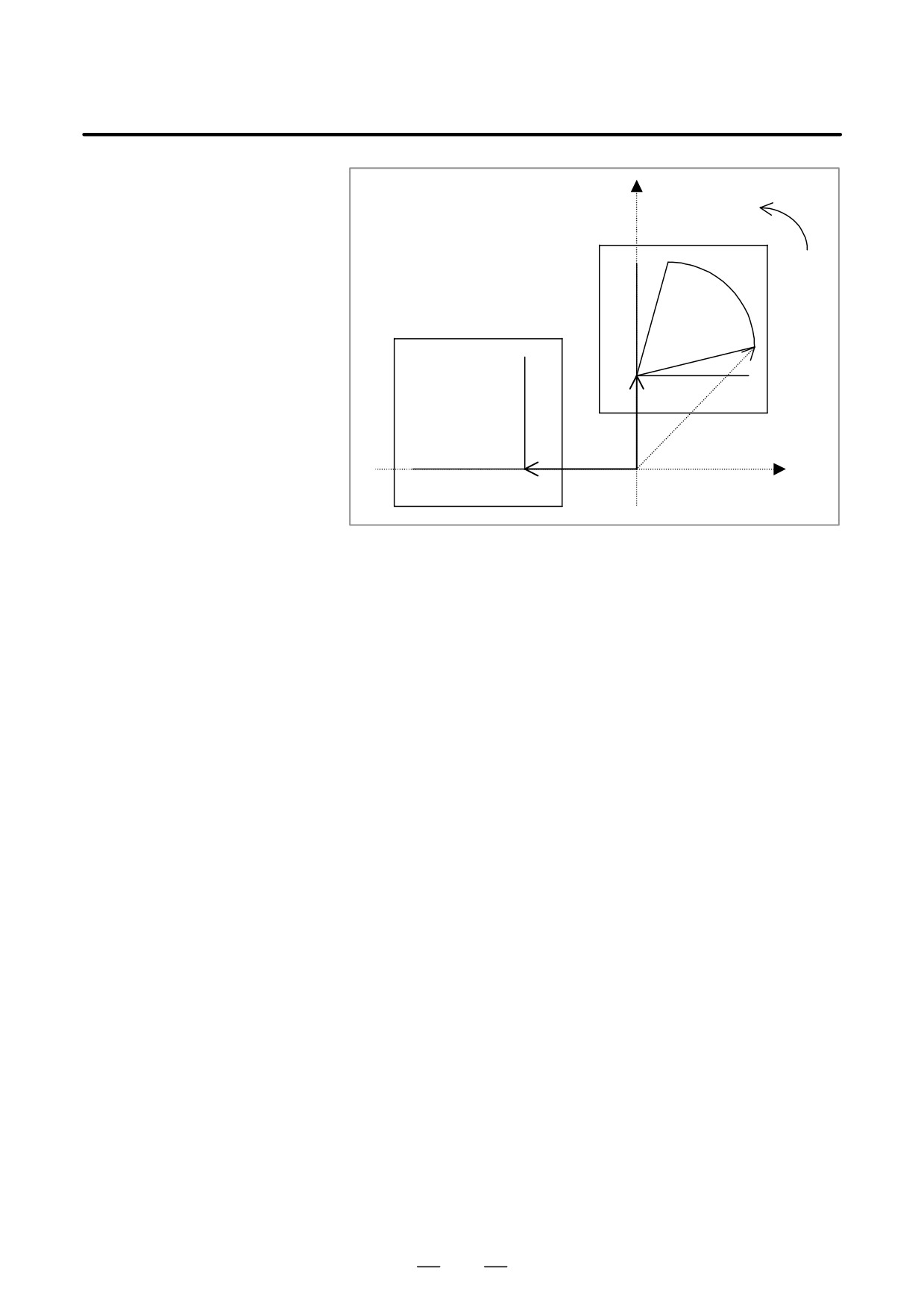
Fig.14.14 (b) Example of fixture offset
When G54.2 P1 is specified in the N2 block, the fixture offset vector (0,
10.0) is calculated. The vector is handled in the same way as the offset
from the workpiece reference point. The current position on the
workpiece coordinate system is (0, -10.0).
If bit 0 (FTP) of parameter 7570 is set to 0, the tool is moved according
to the vector. The resultant position on the workpiece coordinate system
is (0, 0), the position before the command is specified.
391
15. CUSTOM MACRO
PROGRAMMING
B-63534EN/02
CUSTOM MACRO
15
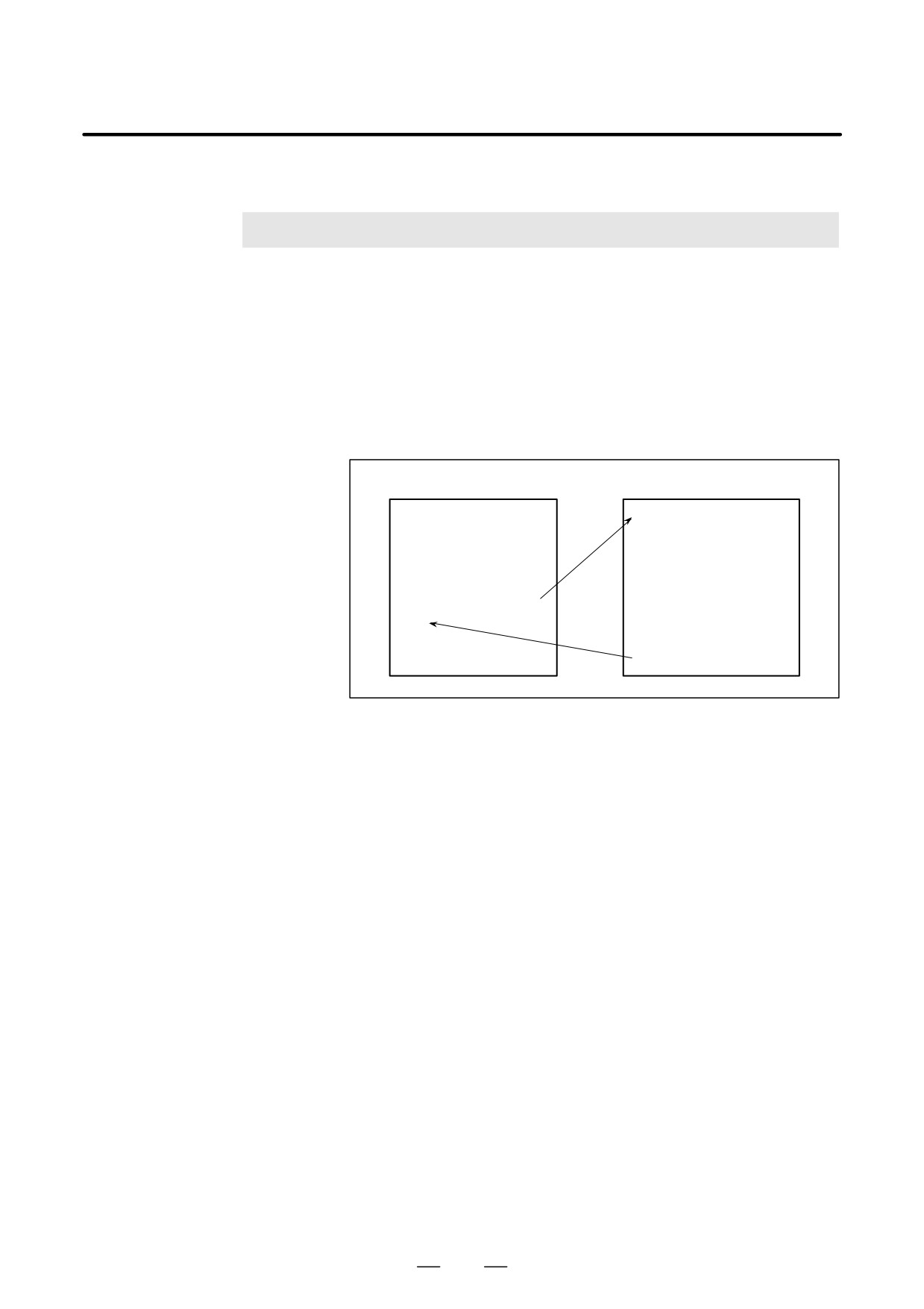
Although subprograms are useful for repeating the same operation, the
custom macro function also allows use of variables, arithmetic and logic
operations, and conditional branches for easy development of general
programs such as pocketing and user-defined canned cycles.A machining
program can call a custom macro with a simple command, just like a
subprogram.
Machining program
Custom macro
O0001 ;
O9010 ;
:
#1=#18/2 ;
:
G01 G42 X#1 Y#1 F300 ;
:
G02 X#1 Y-#1 R#1 ;
G65 P9010 R50.0 L2 ;
:
:
:
:
:
M30 ;
M99 ;
392
PROGRAMMING
15. CUSTOM MACRO
B-63534EN/02
An ordinary machining program specifies a G code and the travel distance
15.1
directly with a numeric value; examples are G100 and X100.0.
VARIABLES
With a custom macro, numeric values can be specified directly or using
a variable number. When a variable number is used, the variable value
can be changed by a program or using operations on the MDI panel.
#1=#2+100 ;
G01 X#1 F300 ;
Explanation
D Variable representation
When specifying a variable, specify a number sign (#) followed by a
variable number. General-purpose programming languages allow a name
to be assigned to a variable, but this capability is not available for custom
macros.
Example: #1
An expression can be used to specify a variable number. In such a case,
the expression must be enclosed in brackets.
Example: #[#1+#2-12]
D Types of variables
Variables are classified into four types by variable number.
Table 15.1 Types of variables
Variable
Type of
Function
number
variable
#0
Always
This variable is always null. No value can
null
be assigned to this variable.
#1 - #33
Local
Local variables can only be used within a
variables
macro to hold data such as the results of
operations. When the power is turned off,
local variables are initialized to null. When
a macro is called, arguments are assigned
to local variables.
#100 - #149 (#199)
Common
Common variables can be shared among
#500 - #531 (#999)
variables
different macro programs. When the pow-
er is turned off, variables #100 to #149 are
initialized to null. Variables #500 to #531
hold data even when the power is turned
off. As an option, common variables #150
to #199 and #532 to #999 are also avail-
able. However, when these values are us-
ing.
#1000 -
System
System variables are used to read and
variables
write a variety of NC data items such as
the current position and tool compensation
values.
NOTE
Common variables #150 to #199 and #532 to #999 are
optional.
393

15. CUSTOM MACRO
PROGRAMMING
B-63534EN/02
D Range of variable values
Local and common variables can have value 0 or a value in the following
ranges :
-1047 to -10-29
0
10-29 to 1047
If the result of calculation turns out to be invalid, an P/S alarm No. 111
is issued.
D Omission of the decimal
When a variable value is defined in a program, the decimal point can be
point
omitted.
Example:
When #1=123; is defined, the actual value of variable #1 is 123.000.
To reference the value of a variable in a program, specify a word address
D Referencing variables
followed by the variable number. When an expression is used to specify
a variable, enclose the expression in brackets.
Example: G01X[#1+#2]F#3;
A referenced variable value is automatically rounded according to the
least input increment of the address.
Example:
When G00X#1; is executed on a 1/1000-mm CNC with 12.3456
assigned to variable
#1, the actual command is interpreted as
G00X12.346;.
To reverse the sign of a referenced variable value, prefix a minus sign (-)
to #.
Example: G00X-#1;
When an undefined variable is referenced, the variable is ignored up to an
address word.
Example:
When the value of variable #1 is 0, and the value of variable #2 is null,
execution of G00X#1Y#2; results in G00X0;.
D Common custom macro
For two-path control, macro variables are provided for each path. Some
variables for tow paths
common variables, however, can be used for both paths, by setting
(two-path control)
parameters No. 6036 and 6037 accordingly.
D Undefined variable
When the value of a variable is not defined, such a variable is referred to
as a “null” variable. Variable #0 is always a null variable. It cannot be
written to, but it can be read.
(a) Quotation
When an undefined variable is quotated, the address itself is also
ignored.
When #1 = < vacant >
When #1 = 0
G90 X100 Y #1
G90 X100 Y #1
#
#
G90 X100
G90 X100 Y0
394
PROGRAMMING
15. CUSTOM MACRO
B-63534EN/02
(b) Operation
< vacant > is the same as 0 except when replaced by < vacant>
When #1 = < vacant >
When #1 = 0
#2 = #1
#2 = #1
#
#
#2 = < vacant >
#2 = 0
#2 = #1*5
#2 = #1*5
#
#
#2 = 0
#2 = 0
#2 = #1+#1
#2 = #1 + #1
#
#
#2 = 0
#2 = 0
(c) Conditional expressions
< vacant > differs from 0 only for EQ and NE.
When #1 = < vacant >
When #1 = 0
#1 EQ #0
#1 EQ #0
#
#
Established
Not established
#1 NE 0
#1 NE 0
#
#
Established
Not established
#1 GE #0
#1 GE #0
#
#
Established
Established
#1 GT 0
#1 GT 0
#
#
Not established
Not established
D Custom macro variables
With the two-path control, macro variables are provided for each path.
common to tool posts
Specifying parameter Nos. 6036 and 6037 allows some of the common
(two-path control)
variables to be used for all paths.
D Displaying variable
Values
VARIABLE
O1234 N12345
NO.
DATA
NO.
DATA
100
123.456
108
101
0.000
109
102
110
103
111
104
112
105
113
106
114
107
115
ACTUAL POSITION (RELATIVE)
X
0.000
Y
0.000
Z
0.000
B
0.000
MEM **** *** ***
18:42:15
[ MACRO ] [ MENU ] [ OPR
] [
] [ (OPRT) ]
D When the value of a variable is blank, the variable is null.
395
15. CUSTOM MACRO
PROGRAMMING
B-63534EN/02
D The mark ******** indicates an overflow (when the absolute
value of a variable is greater than 99999999) or an underflow (when
the absolute value of a variable is less than 0.0000001).
Limitations
Program numbers, sequence numbers, and optional block skip numbers
cannot be referenced using variables.
Example:
Variables cannot be used in the following ways:
O#1;
/#2G00X100.0;
N#3Y200.0;
396
PROGRAMMING
15. CUSTOM MACRO
B-63534EN/02
15.2
System variables can be used to read and write internal NC data such as
tool compensation values and current position data. Note, however, that
SYSTEM VARIABLES
some system variables can only be read. System variables are essential
for automation and general-purpose program development.
Explanations
D Interface signals
Signals can be exchanged between the programmable machine controller
(PMC) and custom macros.
Table 15.2 (a) System variables for interface signals
Variable
Function
number
#1000-#1015
A 16-bit signal can be sent from the PMC to a custom mac-
#1032
ro. Variables #1000 to #1015 are used to read a signal bit
by bit. Variable #1032 is used to read all 16 bits of a signal
at one time.
#1100-#1115
A 16-bit signal can be sent from a custom macro to the
#1132
PMC. Variables #1100 to #1115 are used to write a signal
bit by bit. Variable #1132 is used to write all 16 bits of a
signal at one time.
#1133
Variable #1133 is used to write all 32 bits of a signal at one
time from a custom macro to the PMC.
Note, that values from -99999999 to +99999999 can be
used for #1133.
For detailed information, refer to the connection manual
(B-63523EN-1).
D Tool compensation
Tool compensation values can be read and written using system variables.
values
Usable variable numbers depend on the number of compensation pairs,
whether a distinction is made between geometric compensation and wear
compensation, and whether a distinction is made between tool length
compensation and cutter compensation. When the number of
compensation pairs is not greater than 200, variables #2001 to #2400 can
also be used.
Table 15.2 (b) System variables for tool compensation memory A
Compensation number
System variable
1
#10001 (#2001)
:
:
200
#10200 (#2200)
:
:
999
#10999
Table 15.2 (c) System variables for tool compensation memory B
Compensation
Geometry compensation
Wear compensation
number
1
#11001 (#2201)
#10001 (#2001)
:
:
:
200
#11200 (#2400)
#10200 (#2200)
:
:
:
#11999
#10999
999
397
15. CUSTOM MACRO
PROGRAMMING
B-63534EN/02
Table 15.2 (d) System variables for tool compensation memory C
Cutter compensation
Tool length compensation (H)
(D)
Compensation
number
Geomet-
Wear
Geometric
Wear
ric com-
com-
compensation
compensation
pensation
pensation
1
#11001(#2201)
#10001(#2001)
#13001
#12001
:
:
:
:
:
200
#11201(#2400)
#10201(#2200)
:
:
:
:
:
999
#11999
#10999
#13999
#12999
D Macro alarms
Table 15.2 (e) System variable for macro alarms
Variable
Function
number
#3000
When a value from 0 to 200 is assigned to variable #3000,
the CNC stops with an alarm. After an expression, an alarm
message not longer than 26 characters can be described.
The CRT screen displays alarm numbers by adding 3000 to
the value in variable #3000 along with an alarm message.
Example:
#3000=1(TOOL NOT FOUND);
→ The alarm screen displays ”3001 TOOL NOT FOUND.”
D Stop with a message
Execution of the program can be stopped, and then a message can be
displayed.
Variable
Function
number
#3006
When “#3006=1 (MESSAGE);” is commanded in the macro,
the program executes blocks up to the immediately previous
one and then stops.
When a message of up to 26 characters, which is enclosed
by a control-in character (“(”) and control-out character (“)”),
is programmed in the same block, the message is displayed
on the external operator message screen.
398
PROGRAMMING
15. CUSTOM MACRO
B-63534EN/02
D Time information
Time information can be read and written.
Table 15.2 (f) System variables for time information
Variable
Function
number
#3001
This variable functions as a timer that counts in 1-millisecond
increments at all times. When the power is turned on, the val-
ue of this variable is reset to 0. When 2147483648 millisec-
onds is reached, the value of this timer returns to 0.
#3002
This variable functions as a timer that counts in 1-hour incre-
ments when the cycle start lamp is on. This timer preserves its
value even when the power is turned off. When 9544.371767
hours is reached, the value of this timer returns to 0.
#3011
This variable can be used to read the current date (year/month/
day). Year/month/day information is converted to an apparent
decimal number. For example, September 28, 2001 is repre-
sented as 20010928.
#3012
This variable can be used to read the current time (hours/min-
utes/seconds). Hours/minutes/seconds information is con-
verted to an apparent decimal number. For example, 34 min-
utes and 56 seconds after 3 p.m. is represented as 153456.
D Automatic operation
The control state of automatic operation can be changed.
control
Table 15.2 (g) System variable (#3003) for automatic operation control
Completion of an auxiliary
#3003
Single block
function
0
Enabled
To be awaited
1
Disabled
To be awaited
2
Enabled
Not to be awaited
3
Disabled
Not to be awaited
S When the power is turned on, the value of this variable is 0.
S When single block stop is disabled, single block stop operation is not
performed even if the single block switch is set to ON.
S When a wait for the completion of auxiliary functions (M, S, and T
functions) is not specified, program execution proceeds to the next
block before completion of auxiliary functions. Also, distribution
completion signal DEN is not output.
399