FANUC Series 16i/160i/160is-MB, Series 18i/180i/180is-MB5, Series 18i/180i/180is-MB. Operator's Manual - page 13
14. COMPENSATION FUNCTION
PROGRAMMING
B-63534EN/02
D G28, G30, or G30.1
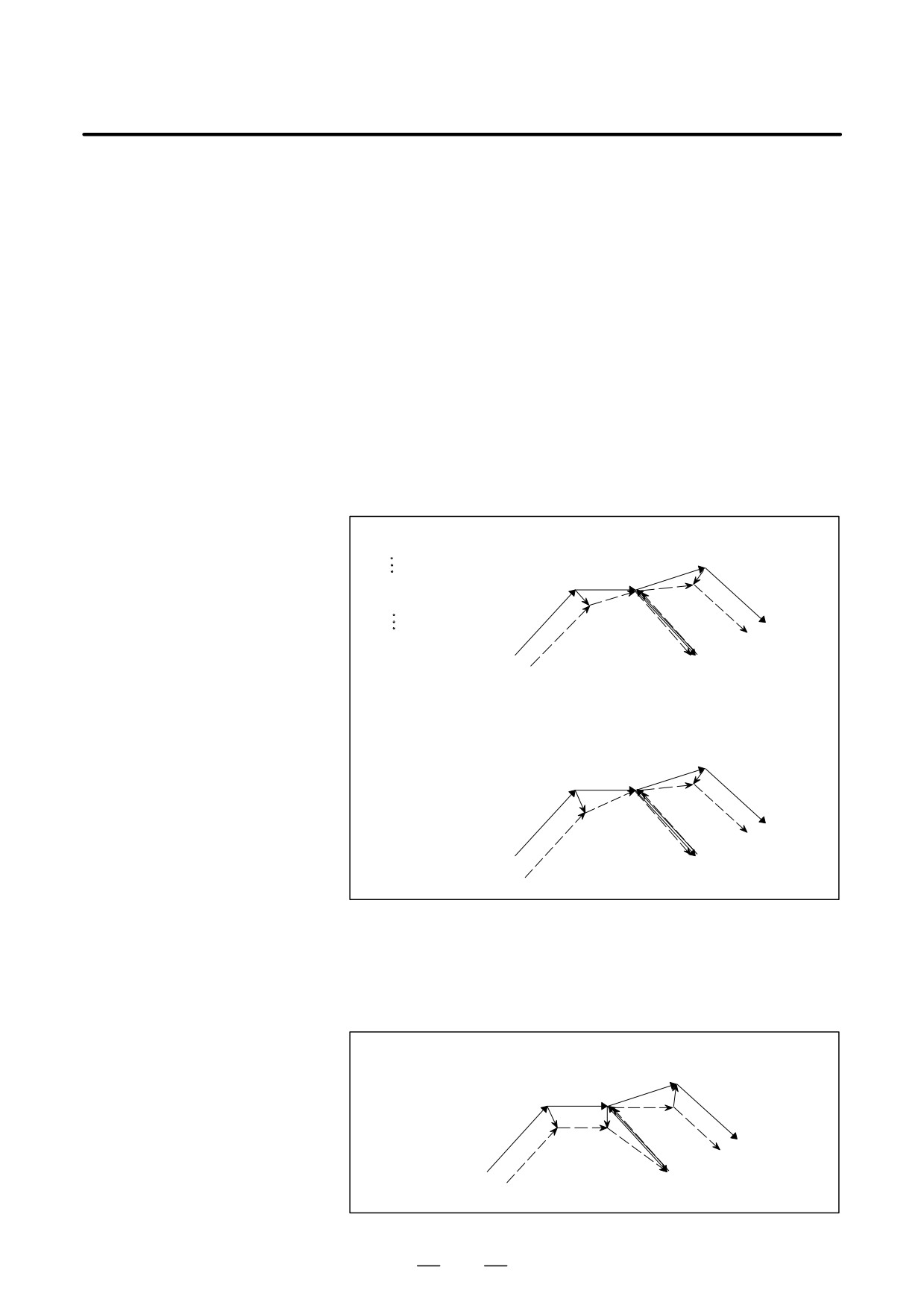
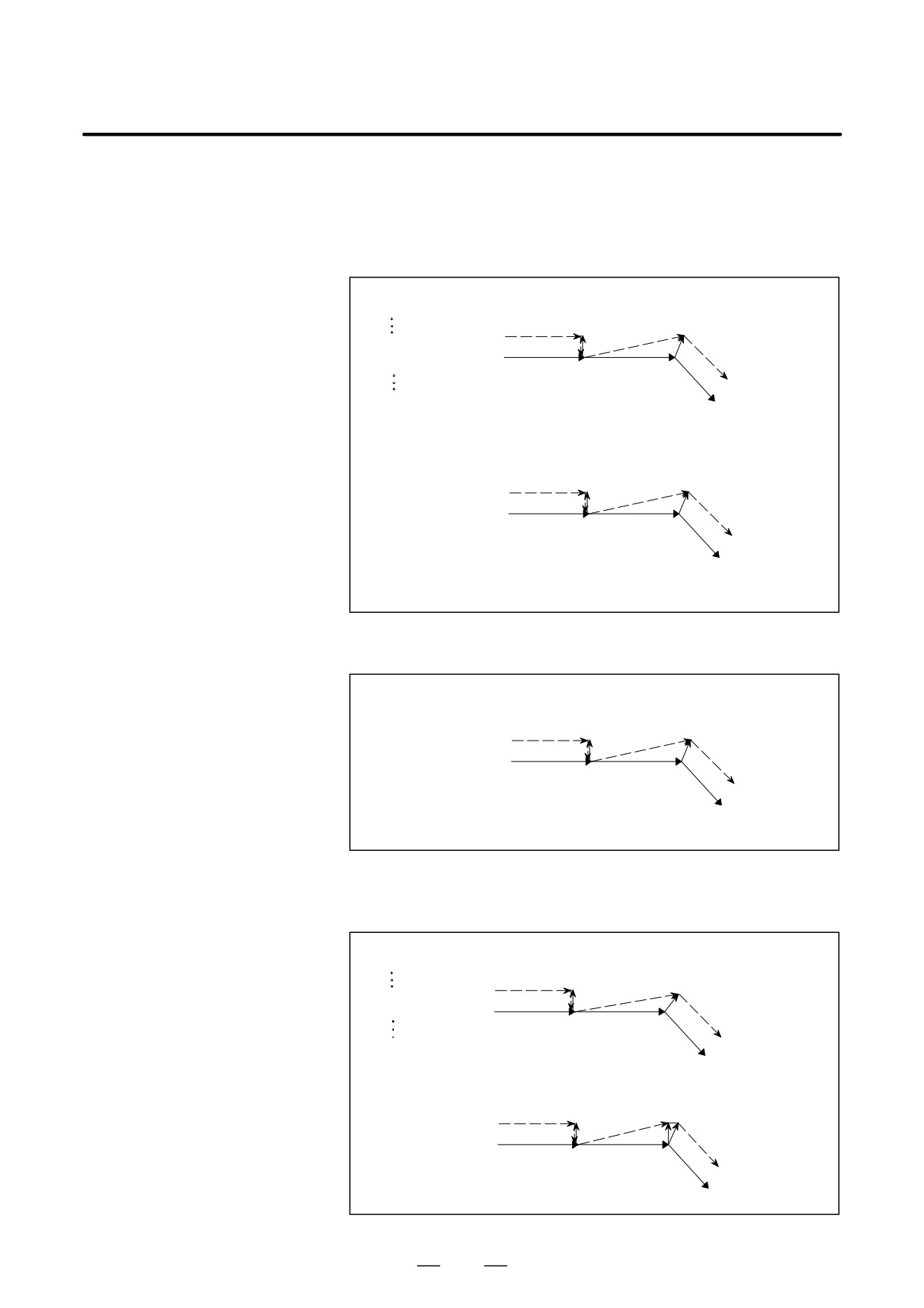
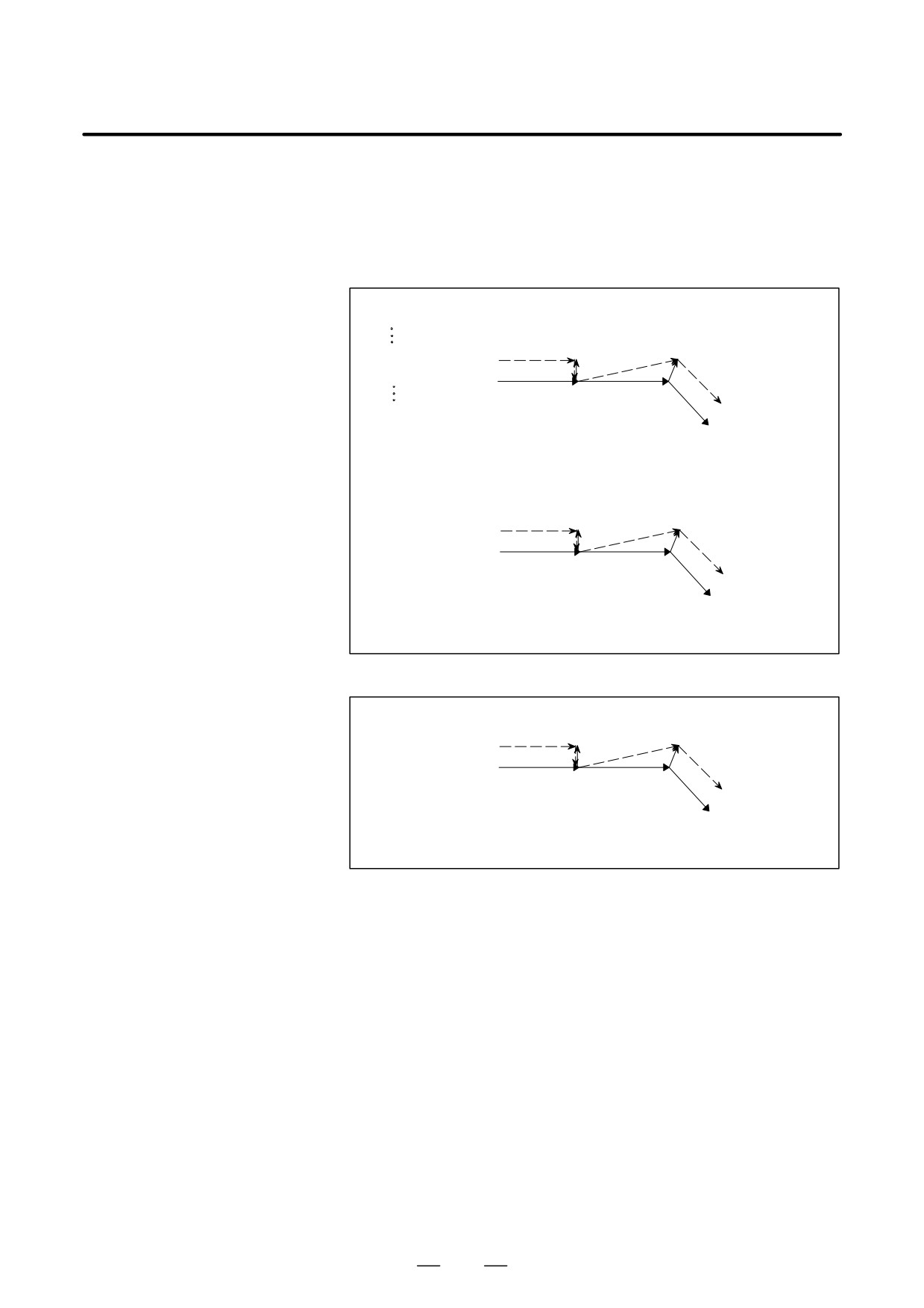
When G28, G30, or G30.1 is specified in cutter compensation C mode,
command in cutter
an operation of FS15 type is performed if CCN (bit 2 of parameter No.
compensation C mode
5003) is set to 1.
This means that an intersection vector is generated in the previous block,
and a perpendicular vector is generated at an intermediate position. Offset
vector cancellation is performed when movement is made from the
intermediate position to the reference position. As part of restoration, an
intersection vector is generated between a block and the next block.
(1) G28, G30, or G30.1, specified in offset mode (with movement to both
an intermediate position and reference position performed)
(a) For return by G29
When CCN (bit 2 of parameter No. 5003) = 0
Oxxxx;
Intermediate
[Type A]
G91G41_ _ _;
position
G28/30/30.1
s Return posiiton
s
r
G01
G28X40.Y0 ;
s
G29X45.Y15. ;
(G42G01)
r
G29
s
Reference position or floating
reference position
[Type B]
Intermediate
position
Return posiiton
G28/30/30.1
s
(G42G01)
s
s
r
G01
G29
s
Reference position or floating
reference position
D G29 command in cutter
compensation C mode
When CCN (bit 2 of parameter No. 5003) = 1
[FS15 Type]
Intermediate
position
G28/30/30.1
s
Return posiiton
s
s
G01
r
(G42G01)
G29
s
Reference position or floating
reference position
340
PROGRAMMING
14. COMPENSATION FUNCTION
B-63534EN/02
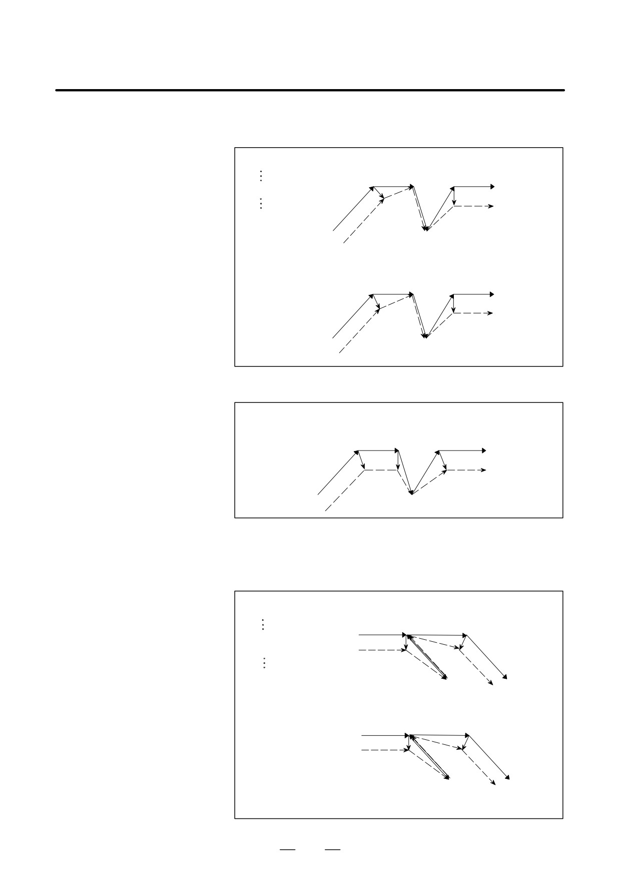
(b) For return by G00
When CCN (bit 2 of parameter No. 5003) = 0
Oxxxx;
[Type A]
G91G41_ _ _;
Intermediateposition
G28/30/30.1
s
s
s G01
G28X40.Y0 ;
r
G00
r
(G42G01)
s
Reference position or floating
reference position
[Type B]
Intermediateposition
G28/30/30.1
s
s
s G01
r
G00
r
(G42G01)
s
Reference position or floating
reference position
When CCN (bit 2 of parameter No. 5003) = 1
[FS15 Type]
Intermediateposition
G28/30/30.1
s
s
s G01
r
r
(G42G01)
G00
Reference position or floating
s
reference position
(2) G28, G30, or G30.1, specified in offset mode (with movement to an
intermediate position not performed)
(a) For return by G29
When CCN (bit 2 of parameter No. 5003) = 0
O××××;
[Type A]
G91G41_ _ _;
Intermediate position = return position
(G42G01)
s
G01
s
G28X0Y0 ;
r
G29X0Y0 ;
G01
G28/30/30.1
G29
Reference position or floating
s
reference position
[Type B]
Intermediate position = return position
(G42G01)
s
G01
s
r
G01
G29
G28/30/30.1
Reference position or floating
s
reference position
341
14. COMPENSATION FUNCTION
PROGRAMMING
B-63534EN/02
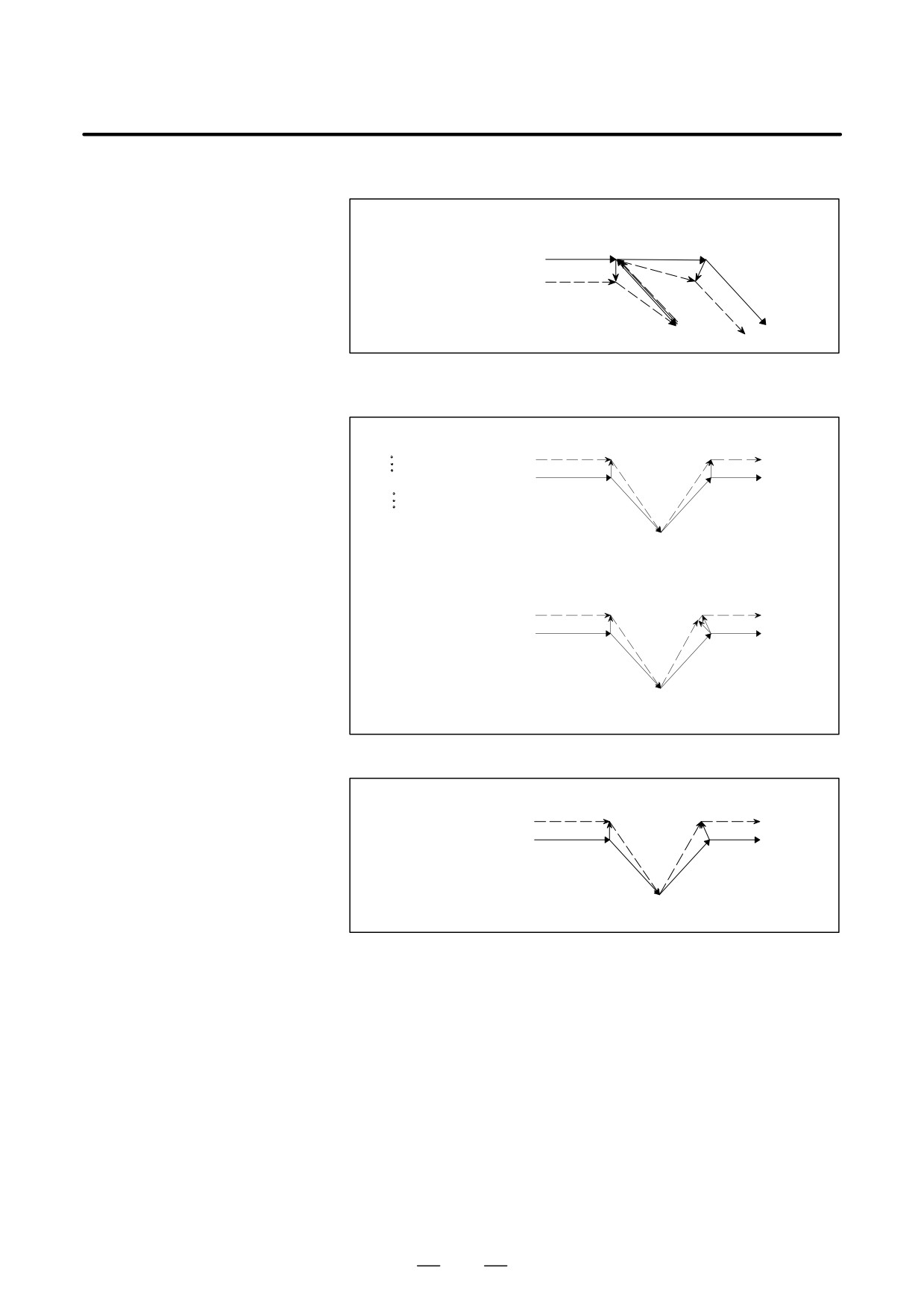
When CCN (bit 2 of parameter No. 5003) = 1
[FS15 Type]
Intermediate position = return position
(G42G01)
s
G01
s
r
G01
G28/30/30.1
G29
Reference position or floating
s
reference position
(b) For return by G00
When CCN (bit 2 of parameter No.5003)=0
Oxxxx;
[Type A]
G91G41_ _ _;
Start-up
r
r
(G42G01)
G28X0Y0 ;
s
s
G01
Intermediate
position
G00
s
G28/30/30.1
Reference position or floating
reference position
[Type B]
Start-up
r
r
(G42G01)
s
s G01
Intermediate
s
G00
position
G28/30/30.1
Reference position or floating
reference position
When CCN (bit 2 of parameter No.5003)=1
[FS15 Type]
s
r
(G41G01)
Intermediate
s
G01
position
s
G00
G28/30/30.1
Reference position or floating
reference position
342
PROGRAMMING
14. COMPENSATION FUNCTION
B-63534EN/02
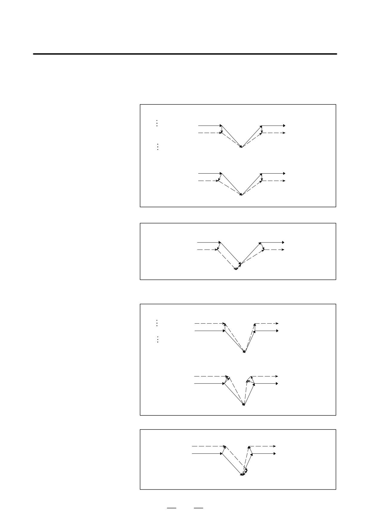
(3) G28, G30, or G30.1, specified in offset mode
(with movement to a reference position not performed)
(a) For return by G29
When CCN (bit 2 of parameter No.5003)=0
Oxxxx;
[Type A]
G91G41_ _ _;
Return position
(G42G01) s
s
G01
r
G28/30/30.1
r
G28X40.Y-40.;
G29
G29X40.Y40.;
s
Reference position or floating
referenceposition=Intermedi-
ate position
[Type B]
Return position
(G42G01)
s
s
G01
G28/30/30.1
r
r
G29
Reference position or floating
s
referenceposition=Intermedi-
ate position
When CCN (bit 2 of parameter No.5003)=1
[FS15 Type]
Return position
(G42G01)
s
s
G01
G28/30/30.1
G29
s
Reference position or floating
r
referenceposition=Intermedi-
ate position
(b) For return by G00
When CCN (bit 2 of parameter No.5003)=0
Oxxxx;
[Type A]
G91G41_ _ _;
Start-up
r
r
G28X40.Y-40.;
(G41G01)
s
s G01
G00
s
G28/30/30.1
Reference position or floating
referenceposition=Intermedi-
ate position
[Type B]
Start-up
r
r
(G41G01)
s
s
G01
G28/30/30.1
s G00
Reference position or floating
referenceposition=Intermedi-
ate position
When CCN (bit 2 of parameter No.5003)=1
[FS15 Type]
(G41G01)
s
s
G01
G28/30/30.1
G00
s
Reference position or floating
r
referenceposition=Intermedi-
ate position
343
14. COMPENSATION FUNCTION
PROGRAMMING
B-63534EN/02
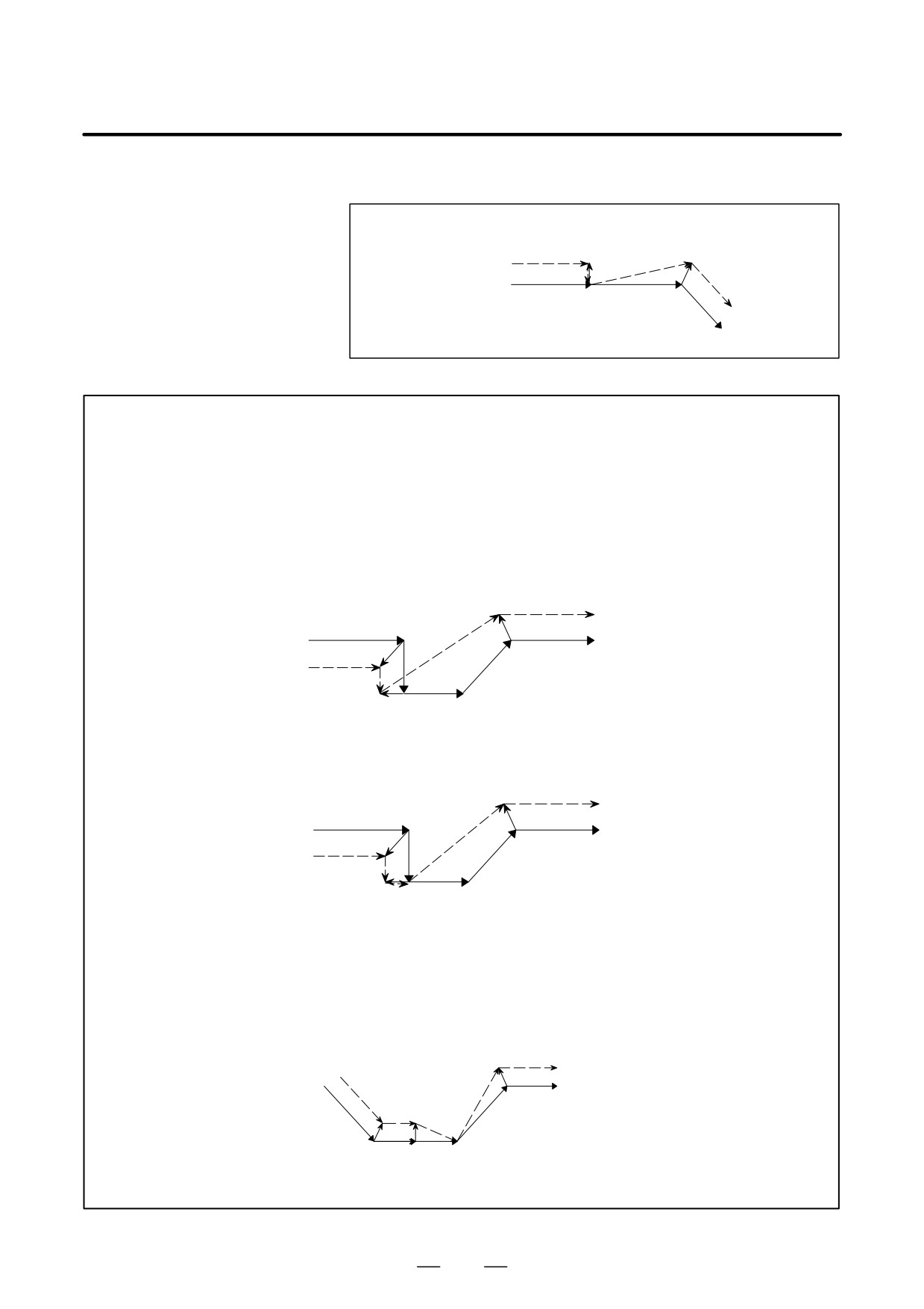
(4) G28, G30, or G30.1 specified in offset mode (with no movement
performed)
(a) For return by G29
When CCN (bit 2 of parameter No.5003)=0
O××××;
[Type A]
G91G41_ _ _;
Intersection vector
G28/30/30.1/G29
G28X0Y0;
(G41G01)
r
G29X0Y0;
s
G01
G01
Reference position or floating
reference position
=Intermediateposition
=return position
[Type B]
Intersection vector
G28/30/30.1/G29
r
(G41G01)
s
G01
G01
Reference position or floating
reference position
=Intermediateposition
=return position
When CCN (bit 2 of parameter No.5003)=1
[FS15 Type]
G28/30/30.1/G29
Intersection vector
(G42G01) r
s
G01
Reference position or floating
G01
reference position
=Intermediateposition
=return position
(b) For return by G00
When CCN (bit 2 of parameter No.5003)=0
O××××;
[Type A]
G91G41_ _ _;
G28/30/30.1
Start-up
G28X0Y0;
(G41G01) r
s
G00
s
Reference position or floating
reference position
G01
=Intermediateposition
[Type B]
Start-up
G28/30/30.1
r
(G41G01)
r
s
G00
s
Reference position or floating
reference position
G01
=Intermediateposition
344
PROGRAMMING
14. COMPENSATION FUNCTION
B-63534EN/02
When CCN (bit 2 of parameter No.5003)=1
[FS15 Type]
G28/30/30.1
r
(G41G01)
s
G00
Reference position or floating G01
reference position
=Intermediateposition
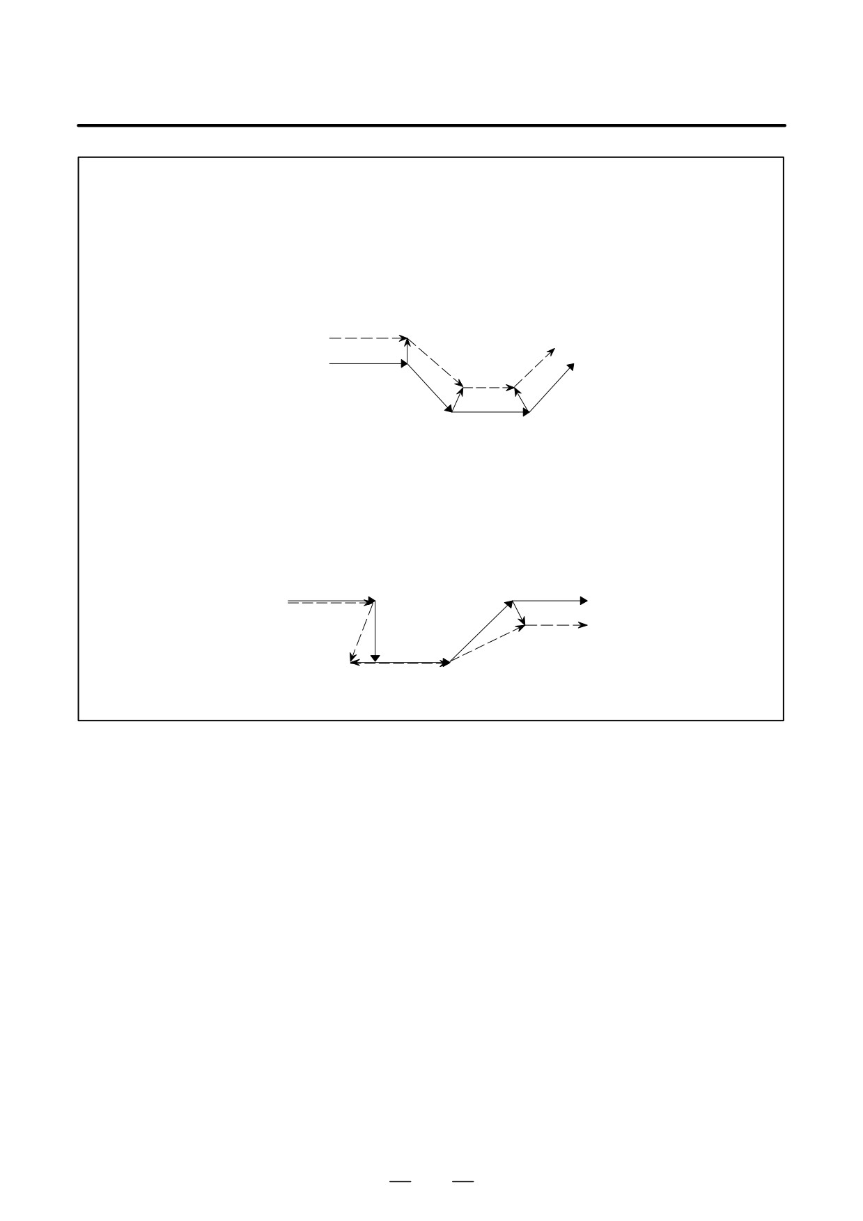
WARNING
1
When a G28, G30, or G30.1 command is specified during all-axis machine lock, a
perpendicular offset vector is applied at the intermediate position, and movement to the
reference position is not performed; the vector is preserved. Note, however, that even if the
FS15 type is used, the vector is canceled only when each-axis machine lock is applied.
(The FS15 type preserves the vector even when each-axis machine lock is applied.)
Example1: When CCN (bit 2 of parameter No.5003)=1
and all-axis machine lock is applied
[FS15Type ]
(G42G01)
rs
G28
s
G01
G01
r
Reference position or floating
s
s
Intermediateposition
reference position
Example2: When CCN (bit 2 of parameter No.5003)=1
and each-axis machine lock is applied
[FS15Type]
(G42G01)
s
G28
s
G01
G01
r
Reference position or floating
s
s
Intermediateposition
reference position
2
When G28, G30, or G30.1 is specified for a compensation axis in cutter compensation mode,
the vectors along the other axes are also canceled.
(This also applies when CCN (bit 2 of
parameter No. 5003) is set to 1. When the FS15 type is used, only the vector along a specified
axis is canceled. Note that the FS15 type cancellation differs from the actual FS15 specification
in this point.)
Example:
When CCN (bit 2 of parameter No.5003)=1
s
G00
(G41G00X_Z_)
s s
G00
r
G28Z_
Reference position or floating
Intermediateposition
reference position
345
14. COMPENSATION FUNCTION
PROGRAMMING
B-63534EN/02
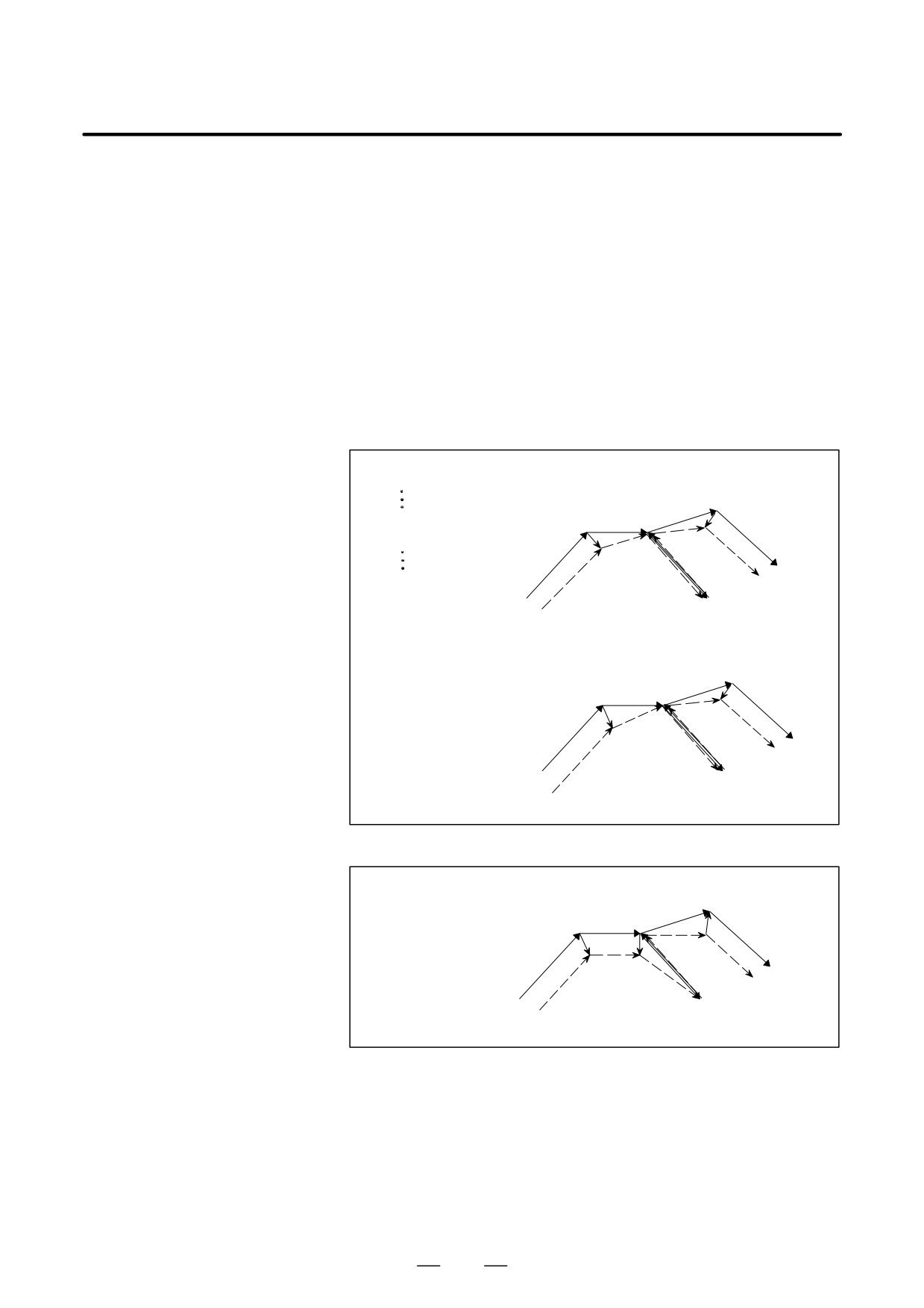
NOTE
1
When a G28, G30, or G30.1 command specifies an axis that is not in the cutter compensation
C plane, a perpendicular vector is generated at the end point of the previous block, and the tool
does not move. In the next block, offset mode is automatically resumed (in the same way as
when two or more continuous blocks do not specify any move commands).
Example:
When CCN (bit 2 of parameter No. 5003) = 1
[FS15 Type]
G28(G30/30.1)Z__
r
(G41G01X_Y_)
s
G01
G01
s
s
2
When a G28, G30, or G30.1 block is specified such that the block becomes a start-up block,
a vector perpendicular to the move direction is generated at an intermediate position, then
subsequently canceled at the reference position. In the next block, an intersection vector is
generated.
Example:
When CCN (bit 2 of parameter No.5003)=1
[FS15 Type]
G01
G01
s
s
G42G28
G01
r
Reference position or floating
reference position
Intermediateposition
s
s
346
PROGRAMMING
14. COMPENSATION FUNCTION
B-63534EN/02
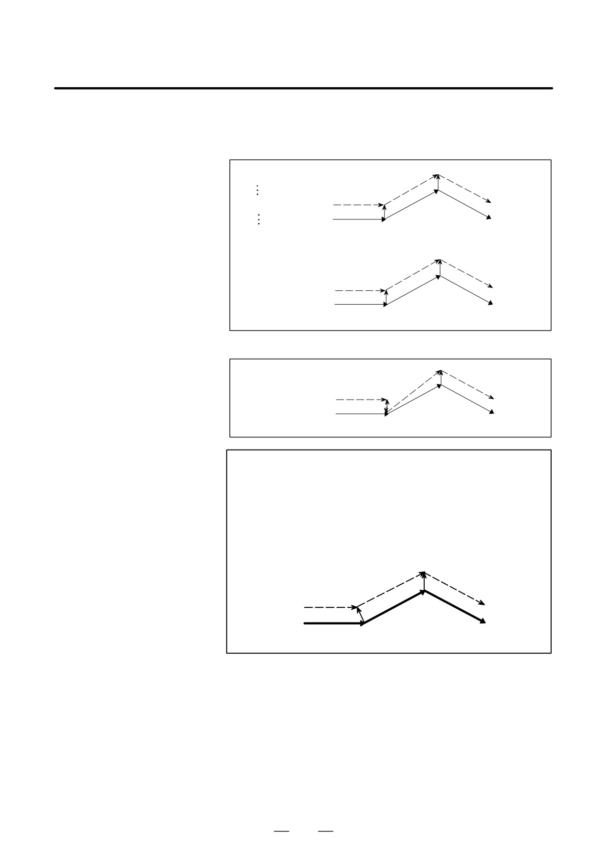
D G29 command in cutter
When G29 is specified in cutter compensation C mode, an operation of
compensation C mode
FS15 type is performed if CCN (bit 2 of parameter No. 5003) is set to 1.
This means that an intersection vector is generated in the previous block,
and vector cancellation is performed when a movement to an intermediate
position is performed. When movement from the intermediate position
to the return position is performed, the vector is restored; an intersection
vector is generated between the block and the next block.
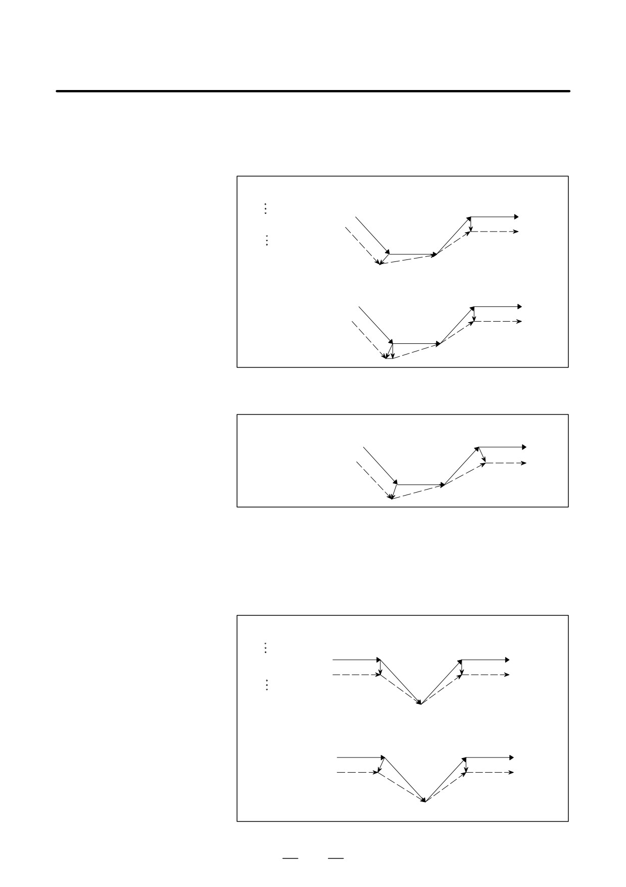
(1) G29 specified in offset mode (with movement to both an intermediate
position and reference position performed)
(a) For specification made immediately after automatic reference
position return
When CCN (bit 2 of parameter No.5003)=0
O××××;
[Tlype A]
G91G41_ _ _;
Intermediate
position
Return position
s
G28/30/30.1
G28X40.Y0;
s
s
G01
G29X45.Y15.;
r
(G42G01)
G29
s
Reference position or floating
reference position
[Type B]
Intermediateposition
Return position
s
G28/30/30.1
G01
s
s
(G42G01)
G29
s
Reference position or floating
reference position
When CCN (bit 2 of parameter No.5003)=1
[FS15Type]
Intermediate
Return position
position
s
G28/30/30.1
s
s
G01
r
(G42G01)
G29
s
Reference position or floating
reference position
347
14. COMPENSATION FUNCTION
PROGRAMMING
B-63534EN/02
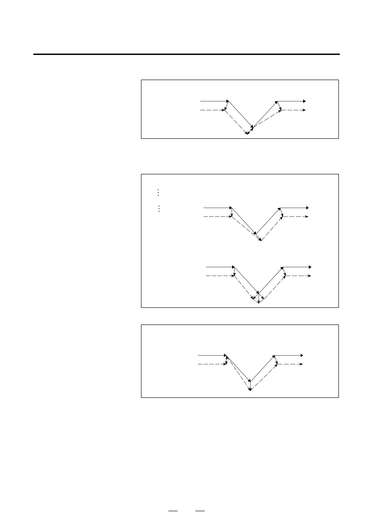
(b) For specification made other than immediately after automatic
reference position return
When CCN (bit 2 of parameter No.5003)=0
O××××;
[Type A]
G91G41_ _ _;
Return position
G01
(G42G01)
s
G29X40.Y40.;
Intermediate
r
position
s
G29
s
Start-up
r
[Type B]
Return position
s
G01
(G42G01)
r
Intermediate
position
s
G29
s
r
Start-up
When CCN (bit 2 of parameter No.5003)=1
[FS15 Type]
Return position
s
G01
(G42G01)
Intermediate
position
s
G29
s
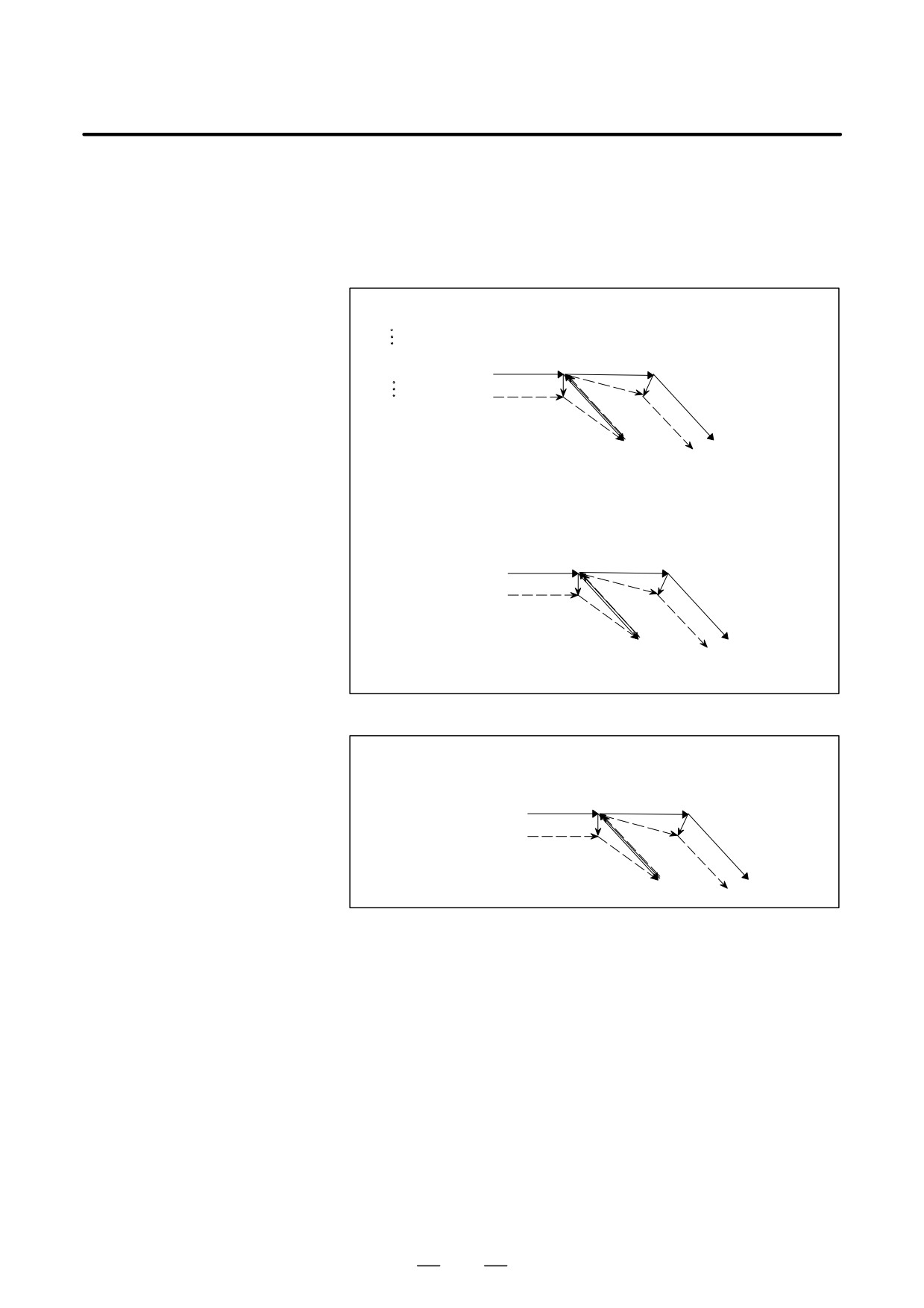
(2) G29 specified in offset mode (with movement to an intermediate
position not performed)
(a) For specification made immediately after automatic reference
position return
When CCN (bit 2 of parameter No.5003)=0
O××××;
[Type A]
G91G41_ _ _;
Return position
(G42G01)
s
s
G01
G28X40.Y-40.;
G28/30/30.1
r
r
G29X40.Y40.;
G29
s
Reference position or floating
referenceposition=Intermedi-
ate position
[Type B]
(G42G01)
Return position
s
s G01
G28/30/30.1
r
G29
s
Reference position or floating
referenceposition=Intermedi-
ate position
348
PROGRAMMING
14. COMPENSATION FUNCTION
B-63534EN/02
When CCN (bit 2 of parameter No.5003)=1
[FS15 Type]
Return position
(G42G01)
s
s
G01
G28/30/30.1
G29
Reference position or floating
s
referenceposition=Intermedi-
r
ate position
(b) For specification made other than immediately after automatic
reference position return
When CCN (bit 2 of parameter No.5003)=0
O××××;
[Type A]
G91G41_ _ _;
Intermediateposition
G29X40.Y-40.;
(G42G01)
s
s G01
r
G29
G01
Start-up
s
r
[Type B]
Return position
Intermediateposition
(G42G01) s
s
G01
r
G29
G01
Start-up
s
r
r
Return position
When CCN (bit 2 of parameter No.5003)=1
[FS15 Type]
Intermediateposition
(G42G01)s
s
G01
r
G29
G01
s
Return position
349
14. COMPENSATION FUNCTION
PROGRAMMING
B-63534EN/02
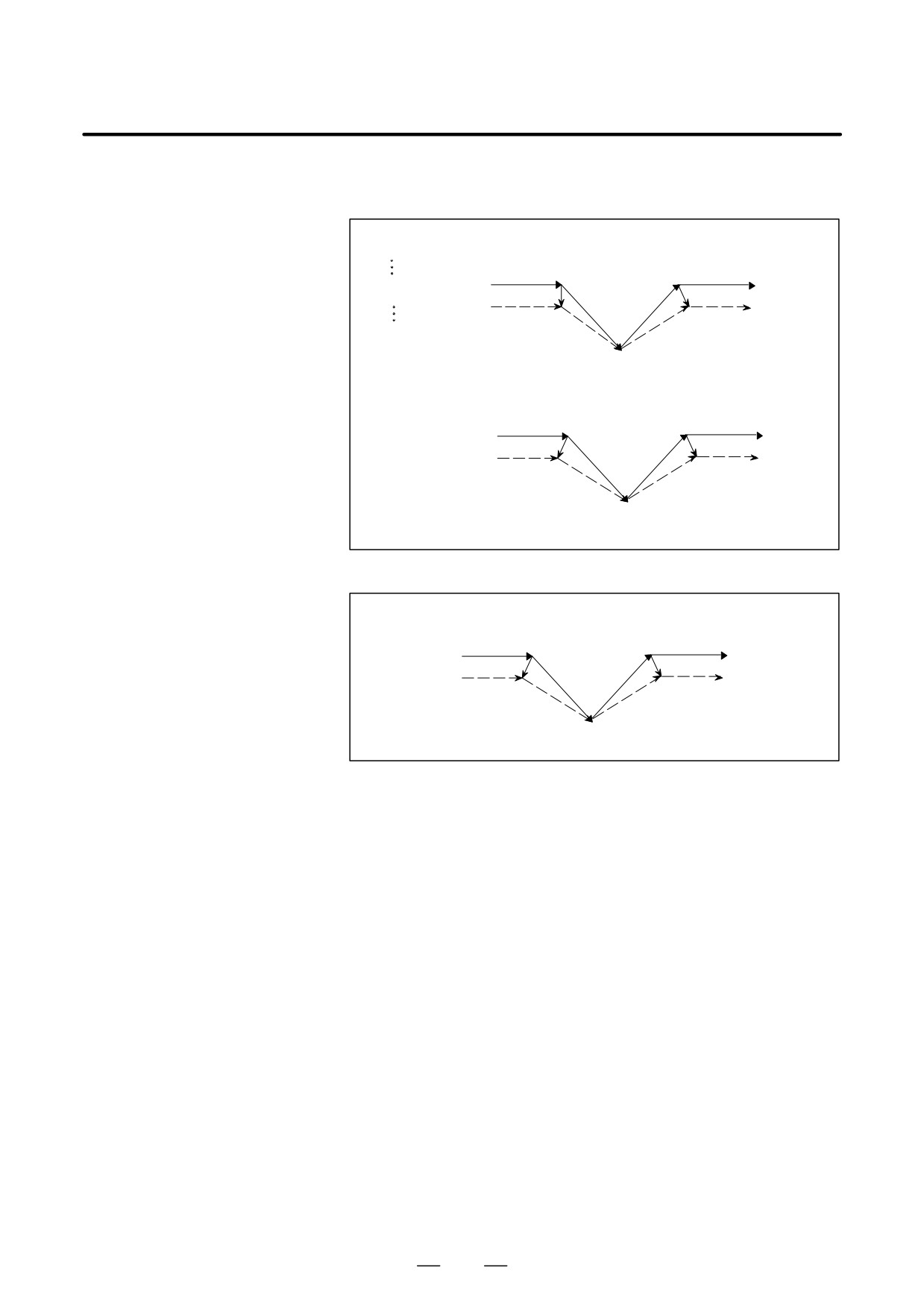
(3) G29 specified in offset mode (with movement to a reference position
not performed)
(a) For specification made immediately after automatic
reference
position return
When CCN (bit 2 of parameter No.5003)=0
O××××;
[Type A]
G91G41_ _ _;
Intermediateposition
=Return position
G28X0Y0;
(G42G01)
G01
s
s
G29X0Y0;
r
G01
G28/30/30.1
G29
s
Reference position or floating
reference position
[Type B]
Intermediateposition
=Return position
(G42G01)
s
G01
s
r
G01
G28/30/30.1
G29
s
Reference position or floating
reference position
When CCN (bit 2 of parameter No.5003)=1
[FS15 Type]
Intermediateposition
=Return position
(G42G01)
s
s
G01
r
G01
G28/30/30.1
G29
Reference position or floating
reference position
s
350
PROGRAMMING
14. COMPENSATION FUNCTION
B-63534EN/02
(b) For specification made other than immediately after automatic
reference position return
O××××;
[Type A]
G91G41_ _ _;
(G42G01)
s
s
G01
G29X0Y0;
r
G29
G01
s
Intermediateposition
=Return position
[Type B]
(G42G01)
s
s
G01
G29
G01
s
Intermediateposition=
Return position
When CCN (bit 2 of parameter No.5003)=1
[FS15 Type]
(G42G01)
s
s G01
G29
G01
s
Intermediateposition
=Return position
351
14. COMPENSATION FUNCTION
PROGRAMMING
B-63534EN/02
(4) G29 specified in offset mode (with movement to an intermediate
position and reference position not performed)
(a) For specification made immediately after automatic reference
position return
When CCN (bit 2 of parameter No.5003)=0
O××××;
[Type A]
G91G41_ _ _;
G28/30/30.1,G29
Intersection vector
G28X0Y0;
s
G29X0Y0;
(G41G01)
r
G01
s
s
G01
Reference position or floating
reference position
=Intermediateposition
=return position
[Type B]
G28/30/30.1,G29
Intersection vector
(G41G01)r
s
G01
s
G01
Reference position or floating
reference position
=Intermediateposition
=return position
When CCN (bit 2 of parameter No.5003)=1
[FS15 Type]
G28/30/30.1,G29
Intersection vector
(G42G01) r
G01
s
s
G01
Reference position or floating
reference position
=Intermediateposition
=return position
352
PROGRAMMING
14. COMPENSATION FUNCTION
B-63534EN/02
(b) For specification made other than immediately after automatic
reference position return
When CCN (bit 2 of parameter No.5003)=0
O××××;
[Type A]
G91G41_ _ _;
G29
s
G29X0Y0;
G01
(G41G01) r
G01
s
Intermediate position=return position
[Type B]
G29
s
r
G01
G01
(G41G01)
s
Intermediate position=return position
When CCN (bit 2 of parameter No.5003)=1
[FS15 Type]
s
G29
G01
G01
r
(G41G01)
s
Intermediate position=return position
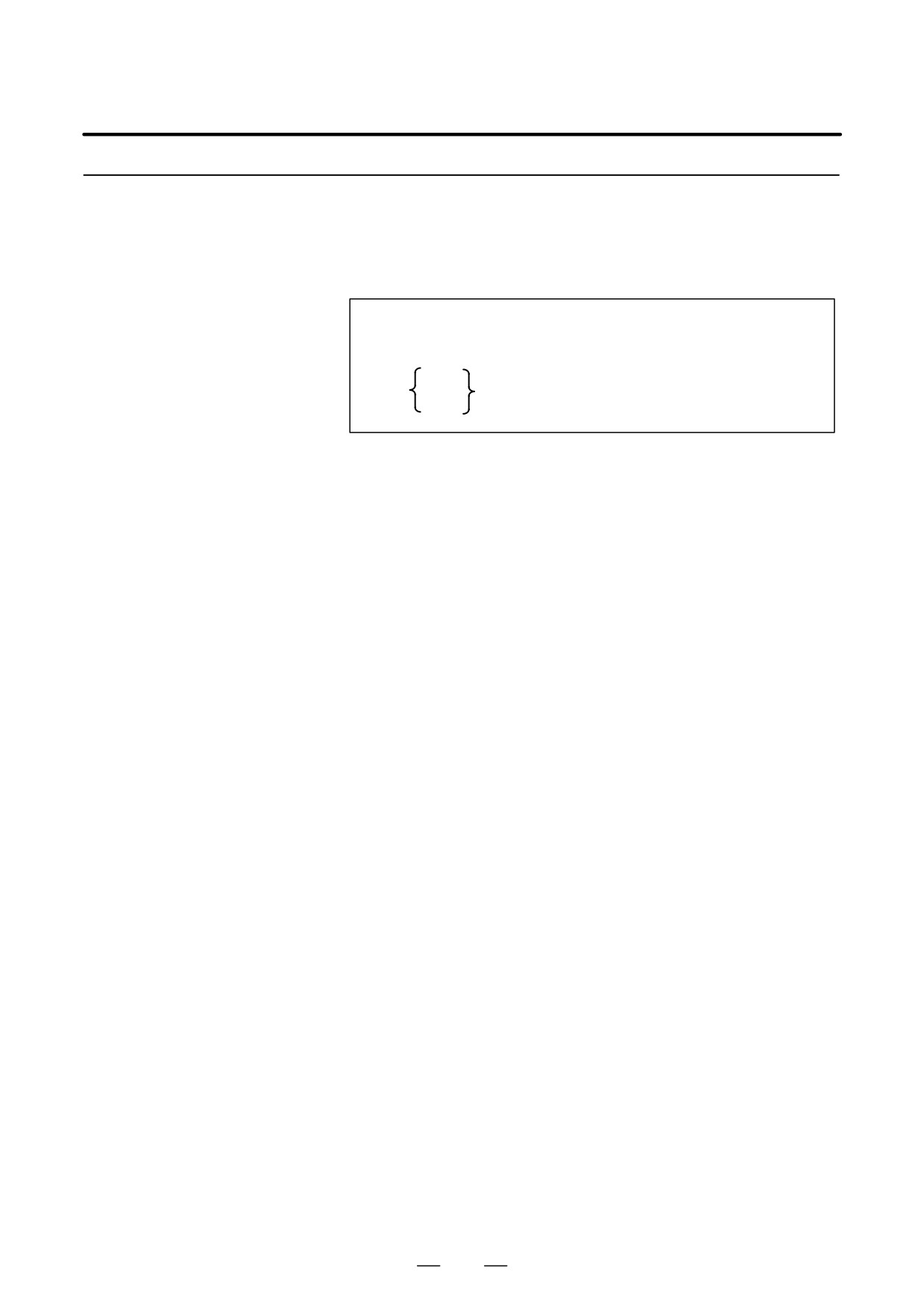
NOTE
When a G29 command is specified for an axis that is not in
the cutter compensation C plane in cutter compensation C
mode, a perpendicular vector is generated at the end point
of the previous block, and the tool does not move. In the
next block, an intersection vector is generated (in the same
way as when two or more continuous blocks do not specify
any move commands).
G29Z__
s
r
G01
G01
s
(G41G01X_Y_)
353
14. COMPENSATION FUNCTION
PROGRAMMING
B-63534EN/02
14.6.9
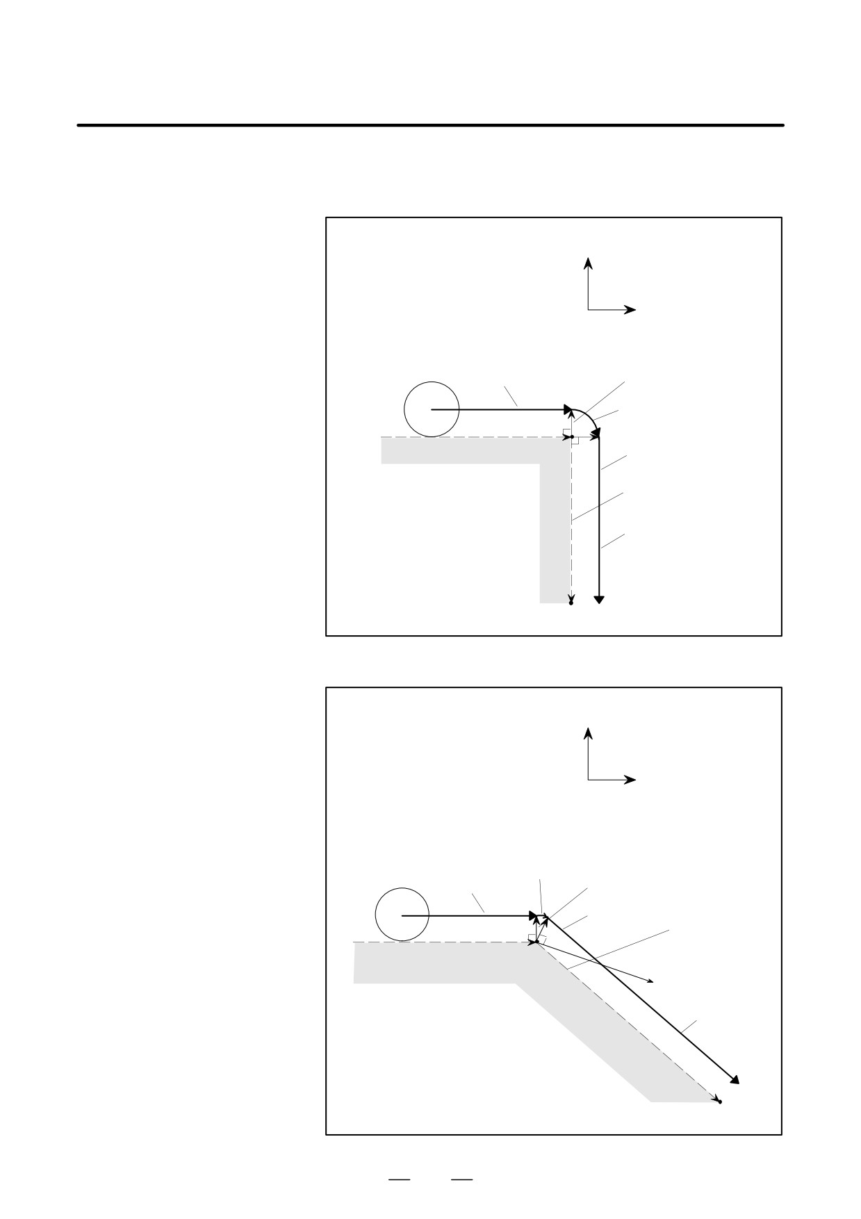
By specifying G39 in offset mode during cutter compensation C, corner
circular interpolation can be performed. The radius of the corner circular
Corner Circular
interpolation equals the compensation value.
Interpolation (G39)
Format
In offset mode
G39 ;
or
I_J_
G39
I_K_
;
J_K_
Explanations
D Corner circular
When the command indicated above is specified, corner circular
interpolation
interpolation in which the radius equals compensation value can be
performed. G41 or G42 preceding the command determines whether the
arc is clockwise or counterclockwise. G39 is a one-shot G code.
D G39 without I, J, or K
When G39; is programmed, the arc at the corner is formed so that the
vector at the end point of the arc is perpendicular to the start point of the
next block.
D G39 with I, J, and K
When G39 is specified with I, J, and K, the arc at the corner is formed so
that the vector at the end point of the arc is perpendicular to the vector
defined by the I, J, and K values.
Limitations
D Move command
In a block containing G39, no move command can be specified.
D Non-move command
Two or more consecutive non-move blocks must not be specified after a
block containing G39 without I, J, or K.
(A single block specifying a
travel distance of zero is assumed to be two or more consecutive
non-move blocks.) If the non-move blocks are specified, the offset
vector is temporarily lost. Then, offset mode is automatically restored.
354
PROGRAMMING
14. COMPENSATION FUNCTION
B-63534EN/02
Examples
D G39 without I, J, or K
X axis
(In offset mode)
N1 Y10.0 ;
N2 G39 ;
Y axis
N3 X-10.0 ;
Block N1
Offset vector
Block N2
(0.0, 10.0)
Block N3
Programmed path
Tool center path
(-10.0, 10.0)
D G39 with I, J, and K
X axis
(In offset mode)
N1 Y10.0 ;
N2 G39 I-1.0 J2.0 ;
Y axis
N3 X-10.0 Y20.0 ;
Block N2
Block N1
Offset vector
Block N3
Programmed
path
(0.0, 10.0)
(I=-1.0, J=2.0)
Tool center
path
(-10.0, 20.0)
355
14. COMPENSATION FUNCTION
PROGRAMMING
B-63534EN/02
14.7
In cutter compensation C, two-dimensional offsetting is performed for a
selected plane. In three-dimensional tool compensation, the tool can be
THREE-
shifted three-dimensionally when a three-dimensional offset direction is
DIMENSIONAL TOOL
programmed.
COMPENSATION
(G40, G41)
Format
D Start up
When the following command is executed in the cutter compensation
cancel mode, the three-dimensional tool compensation mode is set:
(Starting three-
dimensional tool
G41 Xp_ Yp_ Zp_ I_ J_ K_ D_ ;
compensation)
Xp : X-axis or a parallel axis
Yp : Y-axis or a parallel axis
Zp : Z-axis or a parallel axis
I
J
See “Explanation”.
K
D : Code for specifying as the cutter compensation value
(1-3 digits) (D code)
D Canceling
When the following command is executed in the three-dimensional tool
three-dimensional tool
compensation mode, the cutter compensation cancel mode is set:
compensation
⋅When canceling the three-dimensional tool compensation mode and
tool movement at the same time
G40 Xp_ Yp_ Zp_ ;
or
Xp_ Yp_ Zp_ D00 ;
⋅When only canceling the vector
G40;
or
D00;
D Selecting offset space
The three-dimensional space where three-dimensional tool compensation
is to be executed is determined by the axis addresses specified in the startup
block containing the G41 command. If Xp, Yp, or Zp is omitted, the corre-
sponding axis, X-, Y-, or Z-axis (the basic three axis), is assumed.
(Example)
When the U-axis is parallel to the X-axis, the V-axis is parallel to the
Y-axis, and the W-axis is parallel to the Z-axis
G41 X_I_J_K_D_;
XYZ space
G41 U_V_Z_I_J_K_D_;
UVZ space
G41 W_I_J_K_D_;
XYW space
356
B-63534EN/02
PROGRAMMING
14. COMPENSATION FUNCTION
Explanations
D Three-dimensional tool
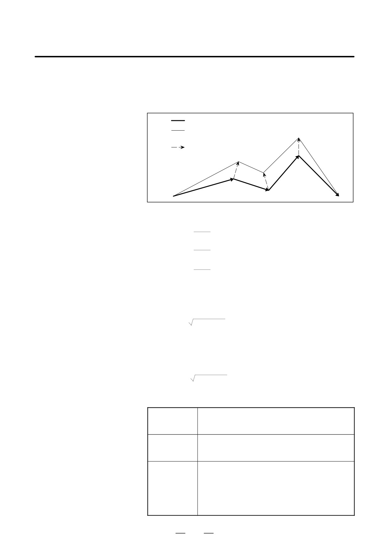
In three-dimensional tool compensation mode, the following three
compensation vector
-dimensional compensation vector is generated at the end of each block:
Programmed path
Path after three-dimensional tool
compensation
Three-dimensional tool
compensation vector
G40
G41
The three-dimensional tool compensation vector is obtained from the
following expressions:
i ⋅ r
Vx =
(Vector component along the Xp-axis)
p
j ⋅ r
Vy =
(Vector component along the Yp-axis)
p
k ⋅ r
Vz =
(Vector component along the Zp-axis)
p
In the above expressions, i, j, and k are the values specified in addresses
I, J, and K in the block. r is the offset value corresponding to the
specified offset number. p is the value obtained from the following
expression:
p=
i2 + j2 + k2
When the user wants to program the magnitude of a three-dimensional
tool compensation vector as well as its direction, the value of p in the
expressions of Vx, Vy, and Vz can be set as a constant in parameter (No.
5011.) If the parameter is set to 0, however, p is determined as follows:
p=
i2 + j2 + k2
D Relationship between
three-dimensional tool
The specified path is shifted by three-dimensional tool com-
compensation and other
Tool length offset
pensation and the subsequent path is shifted by tool length
compensation functions
offset.
When tool offset is specified in the three-dimensional tool
Tool offset
compensation mode, an alarm is issued (P/S alarm No.
042).
When addresses I, J, and K are all specified at startup,
three-dimensional tool compensation mode is set. When
not all of the addresses are specified, cutter compensation
Cutter
C mode is set. Therefore, cutter compensation C cannot be
compensation C
specified in three-dimensional tool compensation mode
and three-dimensional tool compensation cannot be speci-
fied in cutter compensation C mode.
357
14. COMPENSATION FUNCTION
PROGRAMMING
B-63534EN/02
Addresses I, J, and K must all be specified to start three-dimensional tool
D Specifying I, J, and K
compensation. When even one of the three addresses is omitted,
two-dimensional cutter compensation C is activated. When a block
specified in three-dimensional tool compensation mode contains none of
addresses I, J, and K, the same vector as the vector generated in the
previous block is generated at the end of the block.
D G42
Generally, G41 is specified to start three-dimensional tool compensation.
Instead of G41, G42 can be specified for startup. With G42, three-
dimensional tool compensation is performed in the opposite direction.
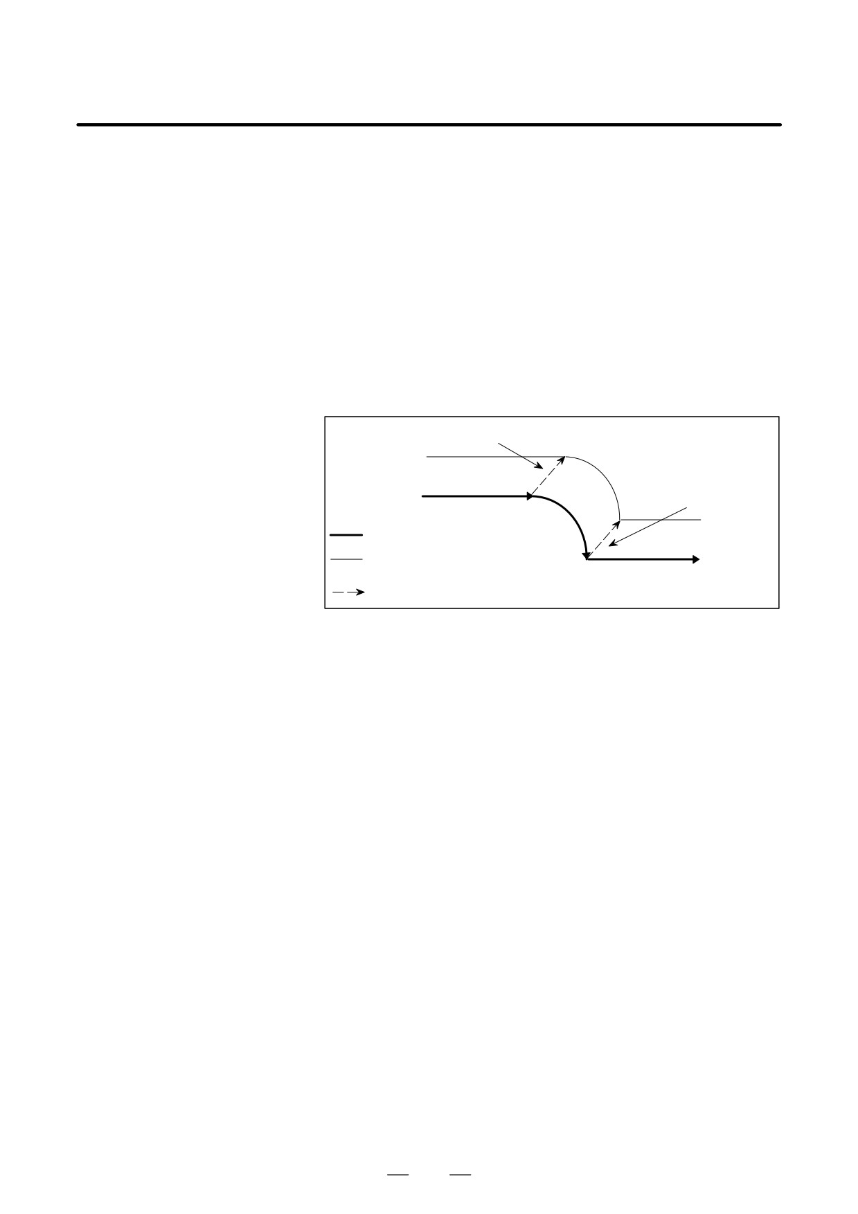
D Offset vector in
When circular interpolation, helical interpolation (both specified with
interpolation
G02, G03), or involute interpolation (G02.2, G03.2) is specified, the
vector generated in the previous block is maintained.
Vector generated in the block before an arc
The same vector is
generated.
Programmed path
Path after three-dimensional
tool compensation
Three-dimensional tool compensation vector
D Reference position
Before specifying reference position return check
(G27), cancel
return check (G27)
three-dimensional tool compensation. In the compensation mode, G27
brings the tool to a position shifted by the offset value. If the position the
tool reached is not the reference position, the reference position return
LED does not go on (the P/S alarm No.092 alarm is issued).
D Return to a reference
When return to the reference position (G28), to the second, third, or fourth
position (G28, G30,
reference position (G30), or to the floating reference position (G30.1) is
G30.1)
specified, the vector is cleared at a middle point.
D Alarm issued at startup
If one of the following conditions is present at the startup of three-
dimensional tool compensation, an alarm is issued:
D Two or more axes are specified in the same direction.
(P/S alarm No.047)
D Although Xp, Yp, or Zp is omitted, the basic three axes are not set.
(P/S alarm No.048)
D Alarm during
If one of the following G codes is specified in the three-dimensional tool
three-dimensional tool
compensation mode, an alarm is issued:
compensation
G05 High-speed cycle machining (P/S alarm178)
G31 Skip function (P/S alarm 036)
G51 Scaling (P/S alarm141)
358
B-63534EN/02
PROGRAMMING
14. COMPENSATION FUNCTION
D Commands that clear the
When one of the following G codes is specified in three-dimensional tool
vector
compensation mode, the vector is cleared:
G73
Peck drilling cycle
G74
Reverse tapping cycle
G76
Fine boring
G80
Canned cycle cancel
G81
Drill cycle, spot boring
G82
Drill cycle, counterboring
G83
Peck drilling cycle
G84
Tapping cycle
G85
Boring cycle
G86
Boring cycle
G87
Back boring cycle
G88
Boring cycle
G89
Boring cycle
G53
Machine coordinate system selection
D Commands that generate
When one of the following G codes is specified in three-dimensional tool
the same vector as the
compensation mode, the same vector as the vector generated in the
vector in the previous
previous block is generated at the end point of the next movement:
block
G02
Circular or helical interpolation (CW)
G03
Circular or helical interpolation (CCW)
G02.2
Involute interpolation (CW)
G03.2
Involute interpolation (CCW)
G04
Dwell
G10
Data setting
G22
Stored stroke check function enabled
359
14. COMPENSATION FUNCTION
PROGRAMMING
B-63534EN/02
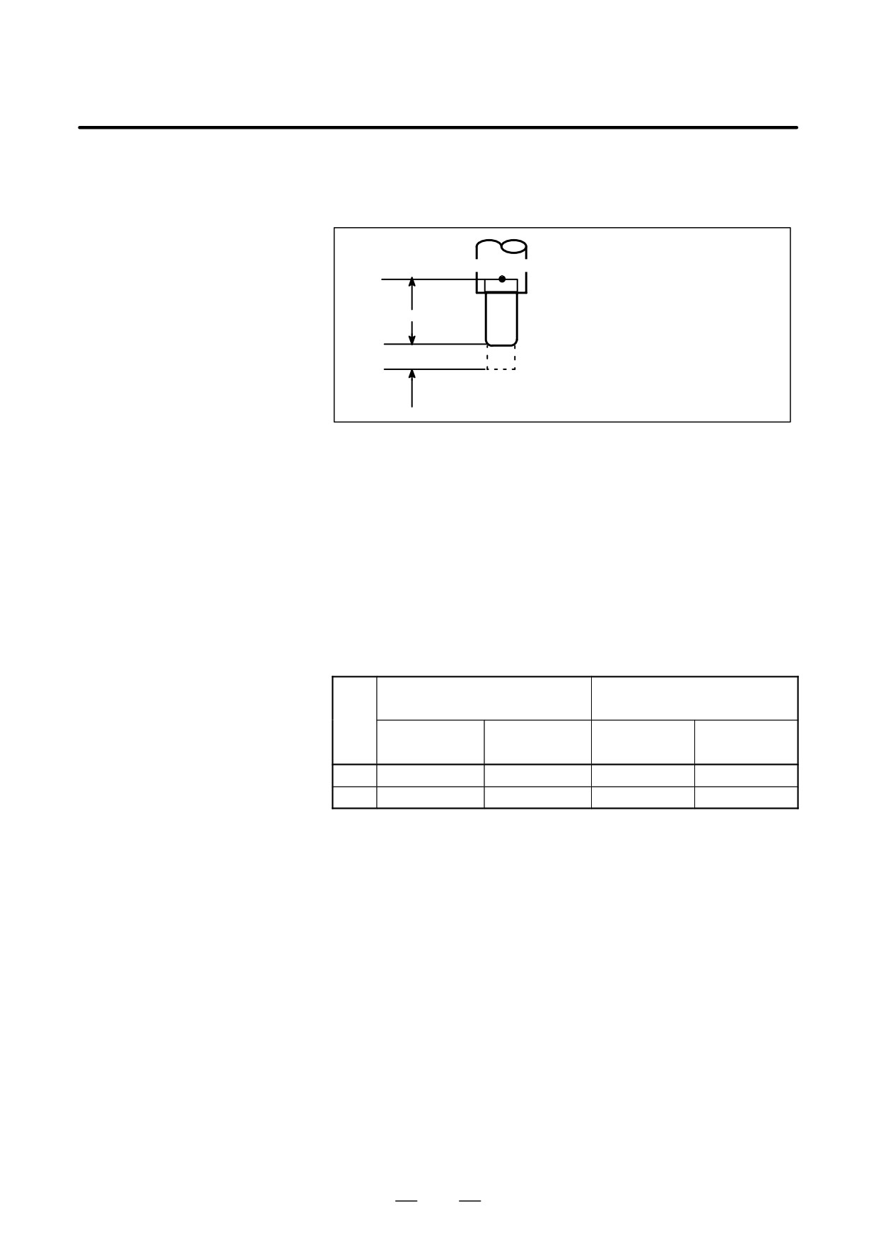
Tool compensation values include tool geometry compensation
14.8
values and tool wear compensation (Fig. 14.8 (a)).
TOOL
COMPENSATION
VALUES, NUMBER
Reference position
OF COMPENSATION
ÇÇ
VALUES, AND
OFSG
ÇÇ
ENTERING VALUES
ÇÇ
FROM THE
OFSW
ÇÇ
OFSG:Geometric compensation value
PROGRAM (G10)
OFSW:Wear compensation value
Fig. 14.8 (a) Geometric compensation and wear compensation
Tool compensation values can be entered into CNC memory from the
CRT/MDI panel (see section III-11.4.1) or from a program.
A tool compensation value is selected from the CNC memory when the
corresponding code is specified after address H or D in a program.
The value is used for tool length compensation, cutter compensation, or
the tool offset.
Explanations
Table 14.8 (a) shows the valid input range of tool compensation values.
D Valid range of tool
compensation values
Table 14.8 (a) The valid input range of tool compensation value
In-
Geometric compensation value
Wear compensation value
cre-
ment
sys-
Metric input
Inch input
Metric input
Inch input
tem
IS-B
"999.999 mm
"99.9999inch
"99.999 mm
"9.9999 inch
IS-C
"999.9999 mm
"99.99999inch
"99.9999 mm
"9.99999 inch
D Number of tool
The memory can hold 32, 64, 99, 200, 400, 499, or 999 tool compensation
compensation values
values (option).
and the addresses to be
Address D or H is used in the program. The address used depends on
specified
which of the following functions is used: tool length compensation(see
II-14.1), tool offset (see II-14.3), cutter compensation B (see II- 14.4),
or cutter compensation C (see II-14.6).
The range of the number that comes after the address (D or H) depens on
the number of tool compensation values : 0 to 32, 0 to 64, 0 to 99, 0 to
200, 0 to 400, 0 to 499, or 0 to 999.
360
B-63534EN/02
PROGRAMMING
14. COMPENSATION FUNCTION
D Tool compensation
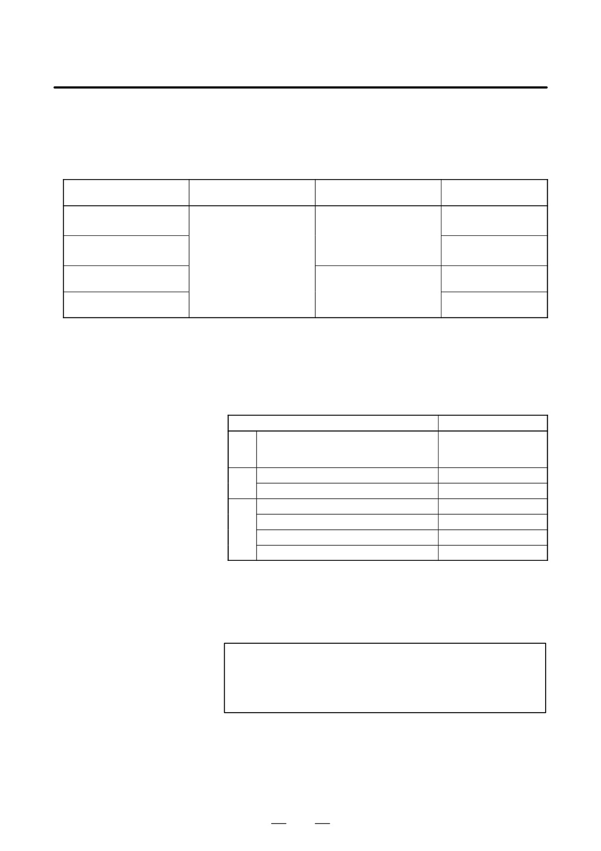
Tool compensation memory A, B, or C can be used.
memory and the tool
The tool compensation memory determines the tool compensation values
compensation value to
that are entered (set) (Table 14.8 (b)).
be entered
Table 14.8 (b) Setting contents tool compensation memory and tool compensation value
Tool compensation
Tool compensation
Tool compensation
Tool compensation value
memory A
memory B
memory C
Tool geometry compensation
Set tool geometry + tool
Set tool geometry com-
set
value for address D
wear compensation values
pensation values for ad-
for addresses D and H (val-
dresses D and H (values can
Tool geometry compensation
ues can be specified with ei-
be specified with either ad-
set
value for address H
ther address).
dress).
Tool wear compensation for
Set tool wear compensation
set
value address D
values for addresses D and
H (values can be specified
Tool wear compensation
with either address).
set
value for address H
Format
The programming format depends on which tool compensation memory
is used.
D Input of tool
compensation value by
Table 14.8 (c) Setting range of Tool compensation memory and
programing
Tool compensation value
Variety of tool compensation memory
Format
Tool compensation value (geometry com-
G10L11P_R_;
A
pensation value+wear compensation val-
ue)
Geometry compensation value
G10L10P_R_;
B
Wear compensation value
G10L11P_R_;
Geometry compensation value for H code
G10L10P_R_;
Geometry compensation value for D code
G10L12P_R_;
C
Wear compensation value for H code
G10L11P_R_;
Wear compensation value for D code
G10L13P_R_;
P : Number of tool compensation
R : Tool compensation value in the absolute command(G90) mode
Value to be added to the specified tool compensation value in the
incremental command(G91) mode (the sum is also a tool
compensation value.)
NOTE
To provide compatibility with the format of older CNC
programs, the system allows L1 to be specified instead of
L11.
361
14. COMPENSATION FUNCTION
PROGRAMMING
B-63534EN/02
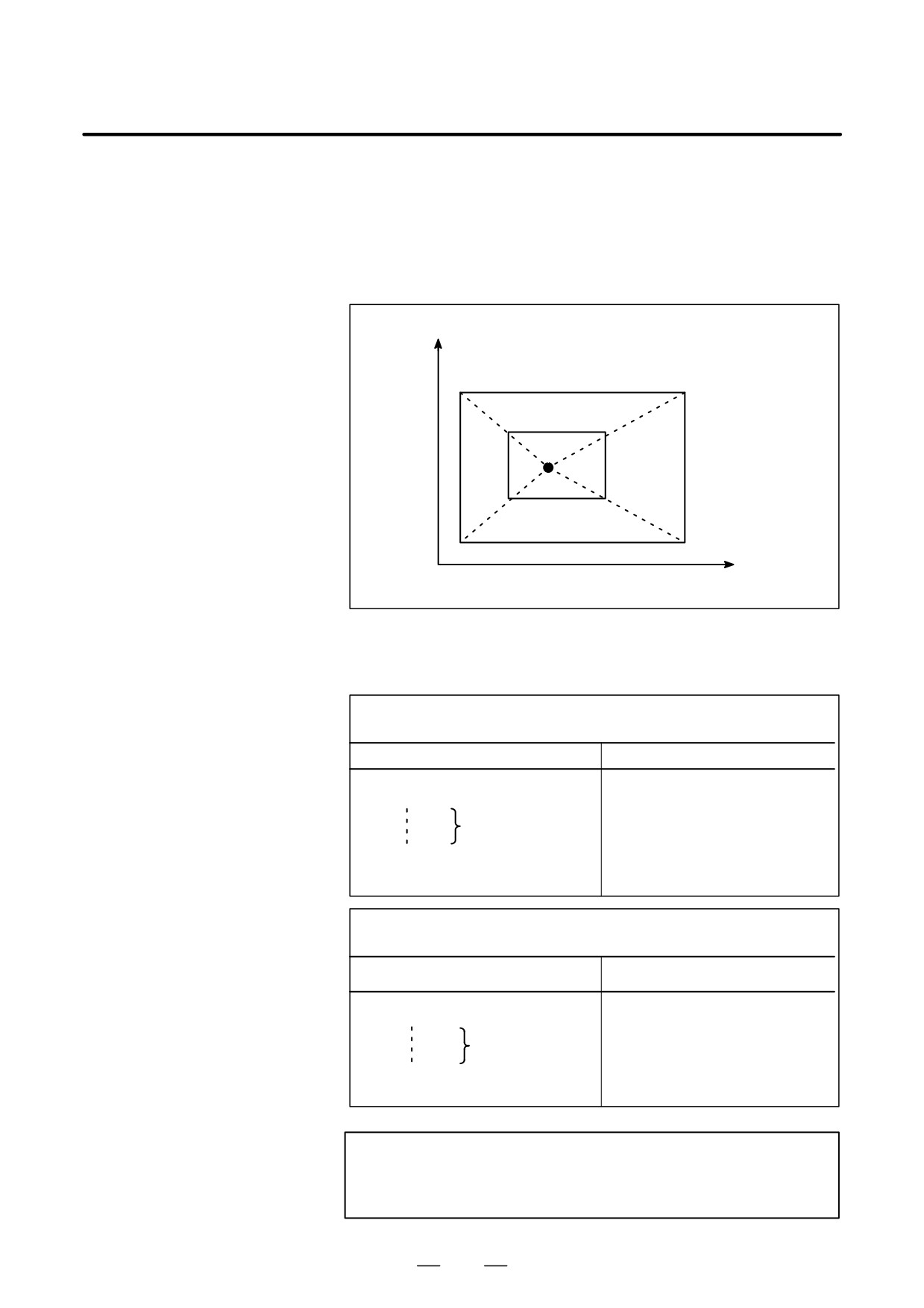
A programmed figure can be magnified or reduced (scaling).
14.9
The dimensions specified with X_, Y_, and Z_ can each be scaled up or
SCALING
down with the same or different rates of magnification.
(G50, G51)
The magnification rate can be specified in the program.
Unless specified in the program, the magnification rate specified in the
parameter is applied.
Y
P4
P
3
P4’
P3’
P0
P2’
P1’
P2
P1
0
X
P0:Scaling center
Fig. 14.9 (a) Scaling(P1 P2 P3 P4³P1’P2’P3’P4’)
Format
SCALING UP OR DOWN ALONG ALL AXES
AT THE SAME RATE OF MAGNIFICATION
Format
Meaning of command
G51X_Y_Z_P_ ; Scaling start
X_Y_Z _ : Absolute command for
center coordinate value
Scaling is effective.
of scaling
(Scaling mode)
P_
: Scaling magnification
G50 ;
Scaling cancel
Scaling up or down along each axes at a different
rate of magnification (mirror image)
Format
Meaning of command
G51_X_Y_Z_I_J_K_;Scaling start
X_Y_Z_ Absolute command for
center coordinate value
Scaling is effective.
of scaling
(Scaling mode)
I_J_K_ Scaling magnification for
X axis Y axis and Z axis
G50
Scaling cancel
respectively
WARNING
Specify G51 in a separate block. After the figure is enlarged
or reduced, specify G50 to cancel the scaling mode.
362
B-63534EN/02
PROGRAMMING
14. COMPENSATION FUNCTION
Explanations
D Scaling up or down
Least input increment of scaling magnification is: 0.001 or 0.00001 It is
along all axes at the
depended on parameter SCR (No. 5400#7) which value is selected. Then,
same rate of
set parameter SCLx (No.5401#0) to enable scaling for each axis. If
magnification
scaling P is not specified on the block of scaling (G51X_Y_Z_P_ ;), the
scaling magnification set to parameter (No. 5411) is applicable. If X,Y,Z
are omitted, the tool position where the G51 command was specified
serves as the scaling center.
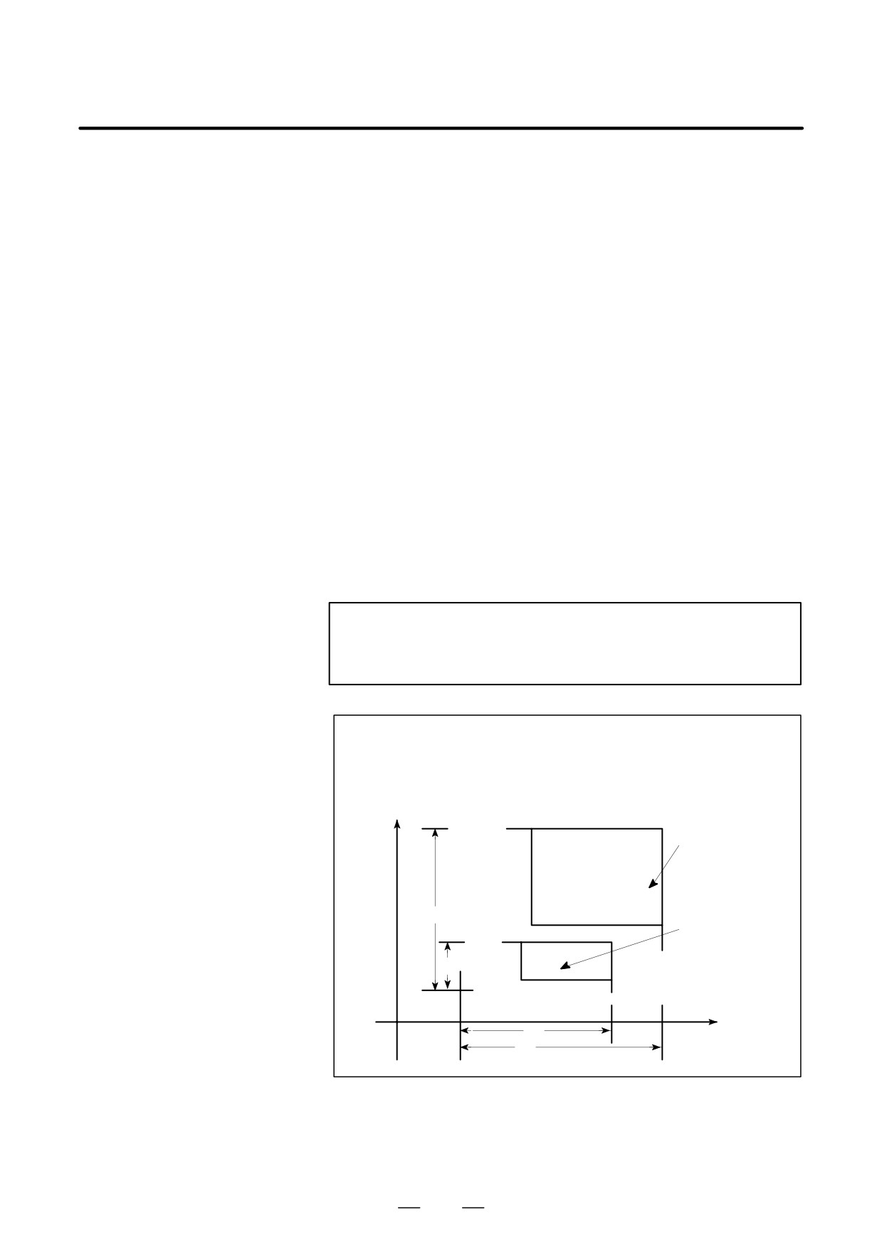
D Scaling of each axis,
Each axis can be scaled by different magnifications. Also when a negative
programmable mirror
magnification is specified, a mirror image is applied. First of all, set a
image
parameter XSC (No. 5400#6) which validates each axis scaling (mirror
(negative magnification)
image).
Then, set parameter SCLx (No. 5401#0) to enable scaling along each axis.
Least input increment of scaling magnification of each axis (I, J, K) is
0.001 or 0.00001( set parameter SCR (No. 5400#7)).
Magnification is set to parameter 5421 within the range +0.00001 to
+9.99999 or +0.001 to +999.999
If a negative value is set, mirror image is effected.
If magnification I, J or K is not commanded, a magnification value set to
parameter (No. 5421) is effective. However, a value other than 0 must be
set to the parameter.
NOTE
Decimal point programming can not be used to specify the
rate of magnification (I, J, K).
a/b : Scaling magnification of X axis
c/d
: Scaling magnification of Y axis
0 : Scaling center
Y axis
Programmed figure
d
Scaled figure
c
0
X axis
a
b
Fig. 14.9 (b) Scaling of each axis
363
14. COMPENSATION FUNCTION
PROGRAMMING
B-63534EN/02
D Scaling of circular
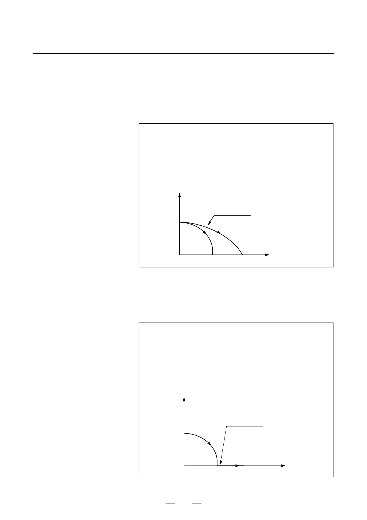
Even if different magnifications are applie to each axis in circular
interpolation
interpolation, the tool will not trace an ellipse.
When different magnifications are applied to axes and a circular
interpolation is specified with radius R, it becomes as following figure
14.9 (c) (in the example shown below, a magnification of 2 is applied to
the X-component and a magnification of
1 is applied to the Y-
component.).
G90 G00 X0.0 Y100.0 ;
G51 X0.0 Y0.0 Z0.0 I2000 J1000;
G02 X100.0 Y0.0 R100.0 F500 ;
Above commands are equivalent to the following command:
G90 G00 X0.0 Y100.0 Z0.0 ;
G02 X200.0 Y0.0 R200.0 F500 ;
Magnification of radius R depends on I, or J whichever is larger.
Y
Scaled shape
X
(0,0)
(100.0)
(200.0)
Fig. 14.9 (c) Scaling for circular interpolation1
When different magnifications are applied to axes and a circular
interpolation is specified with I, J and K, it becomes as following figure
14.9 (d) (In the example shown below, a magnification of 2 is applied to
the X-component and a magnification of 1 is applied to the
Y-component.).
G90 G00 X0.0 Y0.0 ;
G51 X0.0 Y0.0 I2000 J1000;
G02 X100.0 Y0.0 I0.0 J-100.0 F500 ;
Above commands are equivalent to the following commands.
G90 G00 X0.0 Y100.0;
G02 X200.0 Y0.0 I0.0 J-100.0 F500 ;
In this case, the end point does not beet the radius, a linear section is
included.
Y
(200.0)
Scaled shape
(100.0)
(0,0)
(100.0)
(200.0)
X
Fig. 14.9 (d) Scaling for circular interpolation 2
364
B-63534EN/02
PROGRAMMING
14. COMPENSATION FUNCTION
D Tool compensation
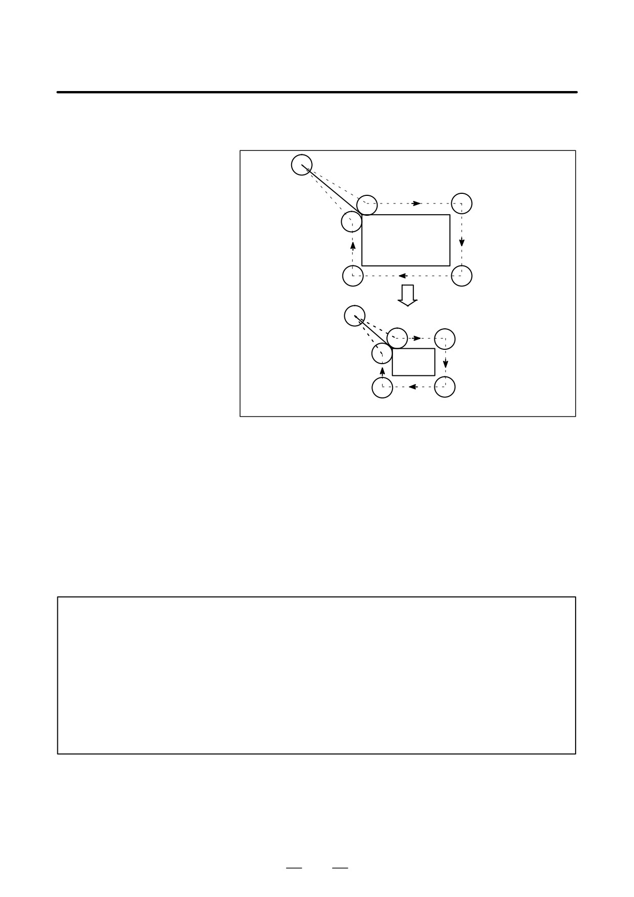
This scaling is not applicable to cutter compensation values, tool length
offset values, and tool offset values (Fig. 14.9 (e) ).
Programmed figure
Scaled figure
Cutter compensation values are not scaled.
Fig. 14.9 (e) Scaling during cutter compensation
D Invalid scaling
Scaling is not applicable to the Z-axis movement in case of the following
canned cycle.
⋅Cut-in value Q and retraction value d of peck drilling cycle (G83, G73).
⋅Fine boring cycle (G76)
⋅Shift value Q of X and Y axes in back boring cycle (G87).
In manual operation, the travel distance cannot be increased or decreased
using the scaling function.
D Commands related to
In scaling mode, G28, G30, or commands related to the coordinate system
reference position return
(G52 to G59) must not be specified. When any of these G codes is
and coordinate system
necessary, specify it after canceling scaling mode.
WARNING
1
If a parameter setting value is employed as a scaling magnification without specifying P, the
setting value at G51 command time is employed as the scaling magnification, and a!change
of this value, if any, is not effective.
2
Before specifying the G code for reference position return (G27, G28, G29, G30) or!coordinate
system setting (G92), cancel the scaling mode.
3
If scaling results are rounded by counting fractions of 5 and over as a unit and disregarding
the rest, the move amount may become zero. In this case, the block is!regarded as a no
movement block, and therefore, it may affect the tool movement by!cutter compensation C. See
the description of blocks that do not move the tool at II-14.6.3.
365
14. COMPENSATION FUNCTION
PROGRAMMING
B-63534EN/02
NOTE
1
The position display represents the coordinate value after scaling.
2
When a mirror image was applied to one axis of the specified plane, the following!results:
(1)Circular command Direction of rotation is reversed.
(2)Cutter compensation C .
Offset direction is reversed.
(3)Coordinate system rotation .
Rotation angle is reversed.
(4)Cutter compensation B .
Offset direction is reversed. (Including G39)
Examples
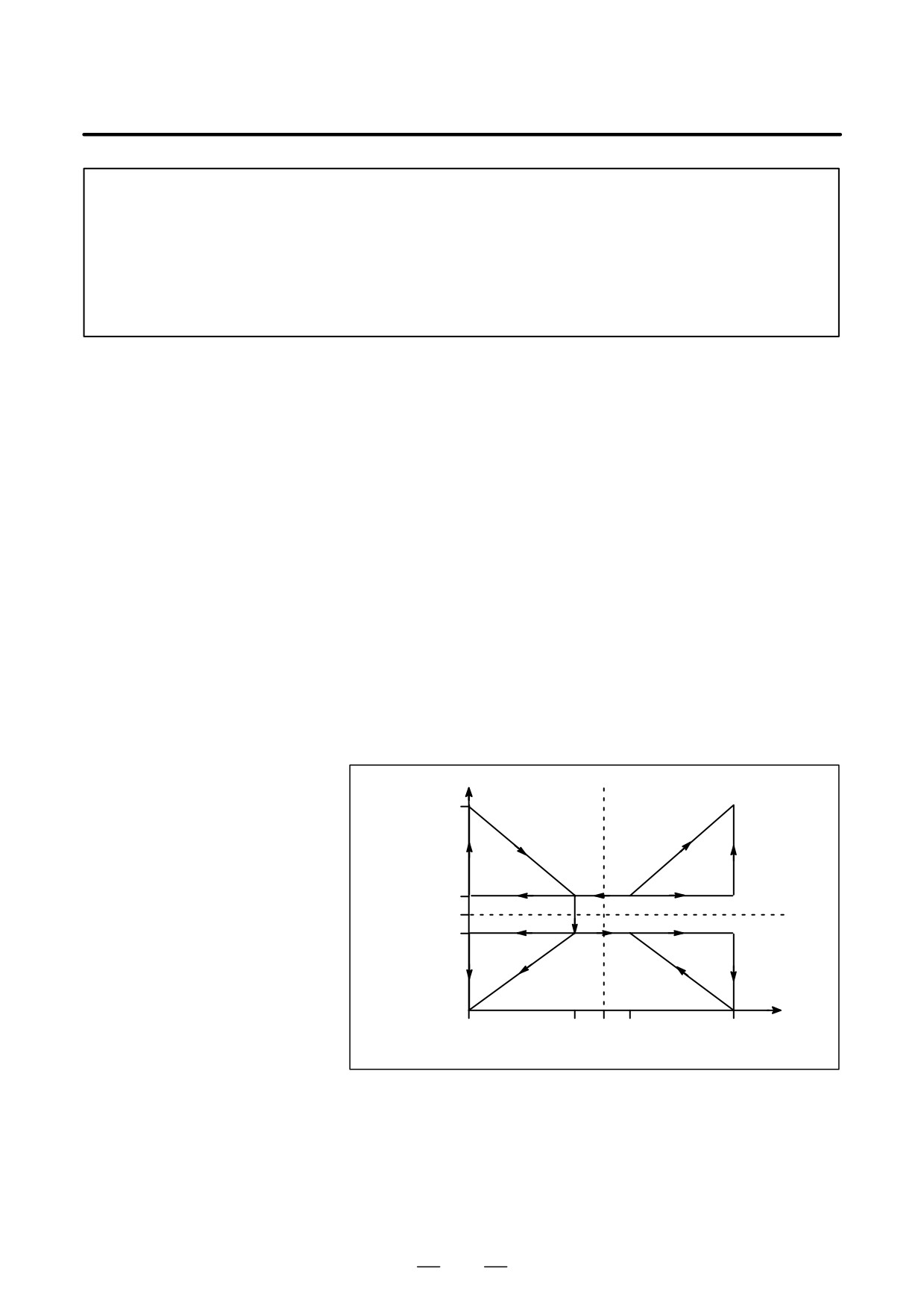
Example of a mirror image program
Subprogram
O9000 ;
G00 G90 X60.0 Y60.0;
G01 X100.0 F100;
G01 Y100.0;
G01 X60.0 Y60.0;
M99;
Main program
N10 G00 G90;
N20M98P9000;
N30 G51 X50.0 Y50.0 I-1000 J1000;
N40 M98 P9000;
N50 G51 X50.0 Y50.0 I-1000 J-1000;
N60 M98 P9000;
N70 G51 X50.0 Y50.0 I1000 J-1000
N80 M98 P9000;
N90 G50;
Y
100
60
50
40
X
0
40
50
60
100
Fig. 14.9 (f) Example of a mirror image program
366
B-63534EN/02
PROGRAMMING
14. COMPENSATION FUNCTION
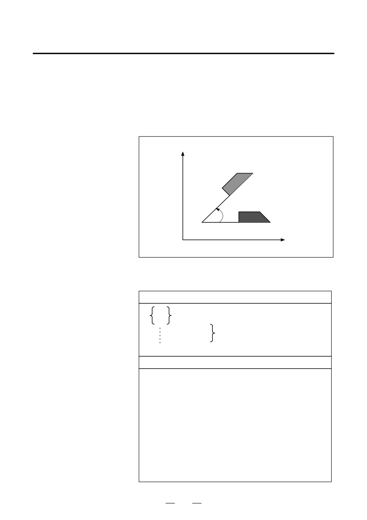
A programmed shape can be rotated. By using this function it becomes
14.10
possible, for example, to modify a program using a rotation command
COORDINATE
when a workpiece has been placed with some angle rotated from the
SYSTEM ROTATION
programmed position on the machine.Further, when there is a pattern
comprising some identical shapes in the positions rotated from a shape,
(G68, G69)
the time required for programming and the length of the program can be
reduced by preparing a subprogram of the shape and calling it after
rotation.
Y
Angle of rotation
Center of rotation
X
0
Fig. 14.10 (a) Coordinate system rotation
Format
Format
G17
G18
G68 α_β_R_ ; Start rotation of a coordinate system.
G19
Coordinate system rotation mode
(The coordinate system is rotated.)
G69 ;
Coordinate system rotation cancel command
Meaning of command
G17 (G18 or G19)
: Select the plane in which contains the figure to be
rotated.
α_β_
Absolute command for two of the x_,y_,and Z_ axes
that correspond to the current plane selected by a
command (G17, G18, or G19). The command
specifies the coordinates of the center of rotation for
the values
specified subsequent to G68.
R_
Angular displacement with a positive value indicates
counter clockwise rotation. Bit 0 of parameter 5400
selects whether the specified angular displacement is
alwarys considered an absolute value or is considered
an absolute or incremental value depending on the
specified G code (G90 or G91).
Least input increment:
0.001 deg
Valid data range
:
-360,000 A360,000
367
14. COMPENSATION FUNCTION
PROGRAMMING
B-63534EN/02
X
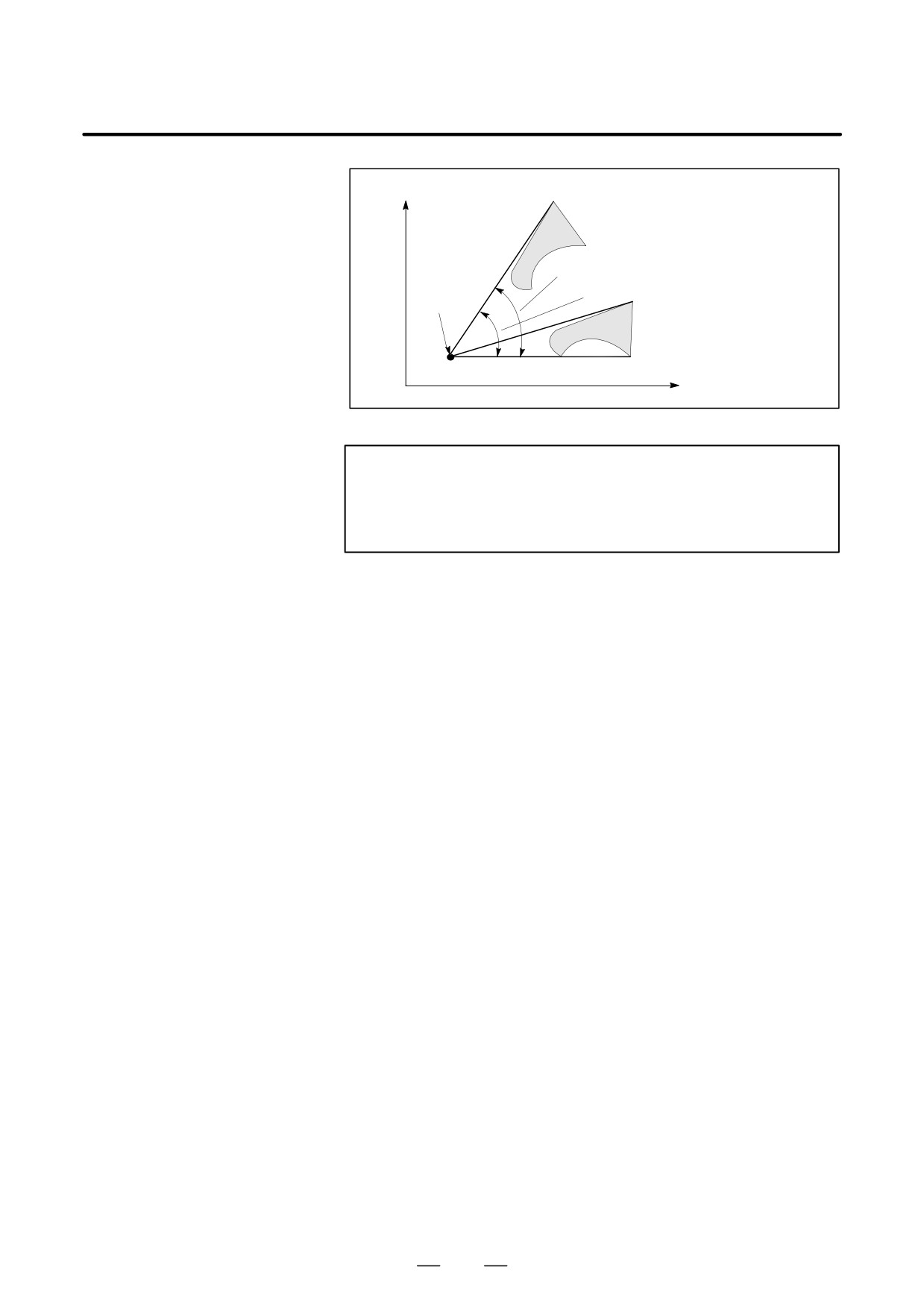
Angle of rotation R (incremental value)
Center of
Angle of rotation (absolute value)
rotation
(α, β)
Z
Fig. 14.10 (b) Coordinate system rotation
NOTE
When a decimal fraction is used to specify angular
displacement (R_), the 1’s digit corresponds to degree
units.
Explanations
D G code for selecting a
The G code for selecting a plane (G17,G18,or G19) can be specified
plane: G17,G18 or G19
before the block containing the G code for coordinate system rotation
(G68). G17, G18 or G19 must not be designated in the mode of coordinate
system rotation.
D Incremental command in
The center of rotation for an incremental command programmed after
coordinate system
G68 but before an absolute command is the tool position when G68 was
rotation mode
programmed (Fig. 14.10 (c)).
D Center of rotation
When α_β_ is not programmed, the tool position when G68 was
programmed is assumed as the center of rotation.
D Angular displacement
When R_ is not specified, the value specified in parameter 5410 is
assumed as the angular displacement.
D Coordinate system
The G code used to cancel coordinate system rotation (G69) may be
rotation cancel
specified in a block in which another command is specified.
command
D Tool compensation
Cutter compensation, tool length compensation, tool offset, and other
compensation operations are executed after the coordinate system is
rotated.
D Relationship with
Both coordinate system rotation and three-dimensional coordinate
three-dimensional
conversion use the same G codes: G68 and G69. The G code with I, J,
coordinate conversion
and K is processed as a command for three-dimensional coordinate
(G68, G69)
conversion. The G code without I, J, and K is processed as a command
for two-dimensional coordinate system rotation.
368
B-63534EN/02
PROGRAMMING
14. COMPENSATION FUNCTION
Limitations
D Commands related to
In coordinate system rotation mode, G codes related to reference position
reference position return
return (G27, G28, G29, G30, etc.) and those for changing the coordinate
and the coordinate
system (G52 to G59, G92, etc.) must not be specified. If any of these G
system
codes is necessary, specify it only after canceling coordinate system
rotation mode.
The first move command after the coordinate system rotation cancel
D Incremental command
command (G69) must be specified with absolute values. If an incremental
move command is specified, correct movement will not be performed.
Explanations
Absolute/Incremental
position commands
N1 G92 X*5000 Y*5000 G69 G17 ;
N2 G68 X7000 Y3000 R60000 ;
N3 G90 G01 X0 Y0 F200 ;
(G91X5000Y5000)
N4 G91 X10000 ;
N5 G02 Y10000 R10000 ;
N6 G03 X*10000 I*5000 J*5000 ;
N7 G01 Y*10000 ;
N8 G69 G90 X*5000 Y*5000 M02 ;
Tool path when the incremental
command is designated in the N3
block (in parenthesis)
Originally programmed tool path
Center of rotation
(7000,3000)
(0,0)
60,
(-500.0,-500.0)
Tool path after rotation
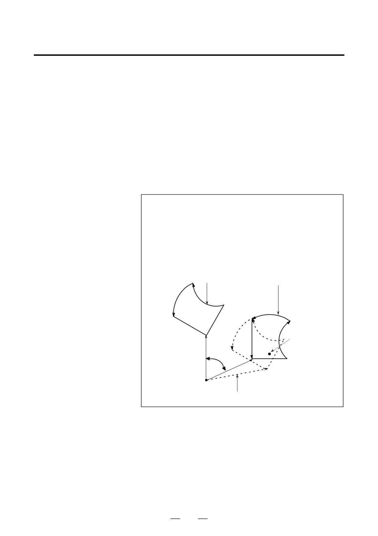
Fig. 14.10 (c) Absolute/incremental command during
coordinate system rotation
369