FANUC Series 16i/160i/160is-MB, Series 18i/180i/180is-MB5, Series 18i/180i/180is-MB. Operator's Manual - page 11
14. COMPENSATION FUNCTION
PROGRAMMING
B-63534EN/02
NOTE
1
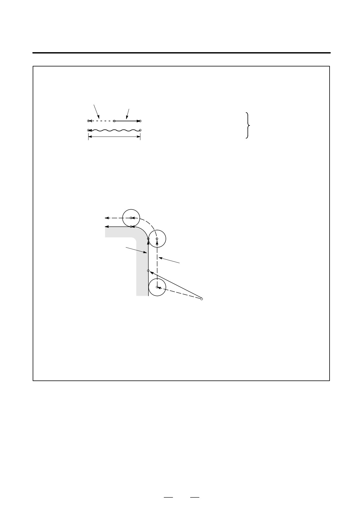
When the specified direction is reversed by decrease as shown in the figure below, the tool
moves in the opposite direction.
Movement of the tool
Program command
Start
Example
End
position
G46 X2.50 ;
position
Tool offset value
Equivalent command
+3.70
X-1.20 ;
Tool offset value
2
Tool offset can be applied to circular interpolation (G02, G03) with the G45 to G48 commands
only for 1/4 and 3/4 circles using addresses I, J and K by the parameter setting, providing that
the coordinate rotation be not specified at the same time. This function is provided for
compatibility with the conventional CNC tape without any cutter compensation. The function
should not be used when a new CNC program is prepared.
Tool offset for circular interpolation
Program
ÇÇ
N4
ÇÇ
N1 G46 G00 X_ Y_ D_ ;
N2 G45 G01 Y_ F_ ;
ÇÇN3ÇÇ
N3 G45 G03 X_ Y_ I_ ;
N4 G01 X_ ;
ÇÇÇ
Programmed tool path
ÇÇ
N2
Actual tool path
ÇÇ
N1
ÇÇÇ
ÇÇÇ
3
D code should be used in tool offset mode (G45 to G48). However, H code can be used by
setting the parameter TPH (No. 5001#5) because of compatibility with conventional CNC tape
format. The H code must be used under tool length offset cancel (G49).
4
G45 to G48 are ignored in canned cycle mode. Perform tool offset by specifying G45 to G48
before entering canned cycle mode and cancel the offset after releasing the canned cycle
mode.
280
PROGRAMMING
14. COMPENSATION FUNCTION
B-63534EN/02
Examples
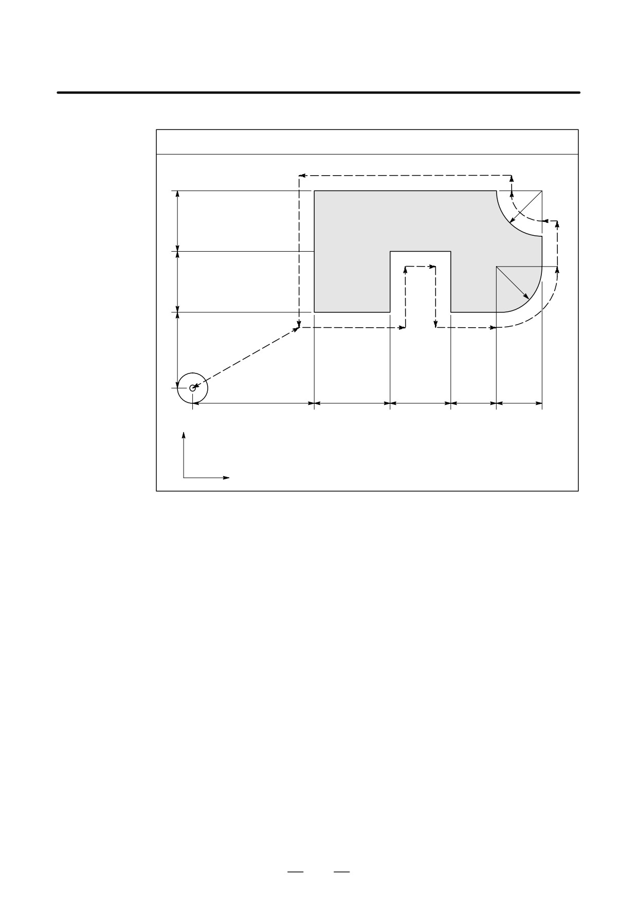
Program using tool offset
N12
N11
30R
N9
40
N10
N13
N8
N4
30R
40
N3
N5
N1
N7
N2
N6
50
ÇÇÇ
N14
ÇÇÇ
80
50
40
30
30
OriginÇÇ
Y axis
Tool diameter
:
20φ
Offset No.
:
01
Tool offset value
:
+10.0
X axis
Program
N1 G91 G46 G00 X80.0 Y50.0 D01 ;
N2 G47 G01 X50.0 F120.0 ;
N3 Y40.0 ;
N4 G48 X40.0 ;
N5 Y-40.0 ;
N6 G45 X30.0 ;
N7 G45 G03 X30.0 Y30.0 J30.0 ;
N8 G45 G01 Y20.0 ;
N9 G46 X0 ;
Decreases toward the positive direction for
movement amount “0”. The tool moves in the -X
direction by theoffset value.
N10 G46 G02 X-30.0 Y30.0 J30.0 ;
N11 G45 G01 Y0 ; Increase toward the positive direction for movement
amount “0”. The tool moves in the +Y direction by
the offset value.
N12 G47 X-120.0 ;
N13 G47 Y-80.0 ;
N14 G46 G00 X80.0 Y-50.0 ;
281
14. COMPENSATION FUNCTION
PROGRAMMING
B-63534EN/02
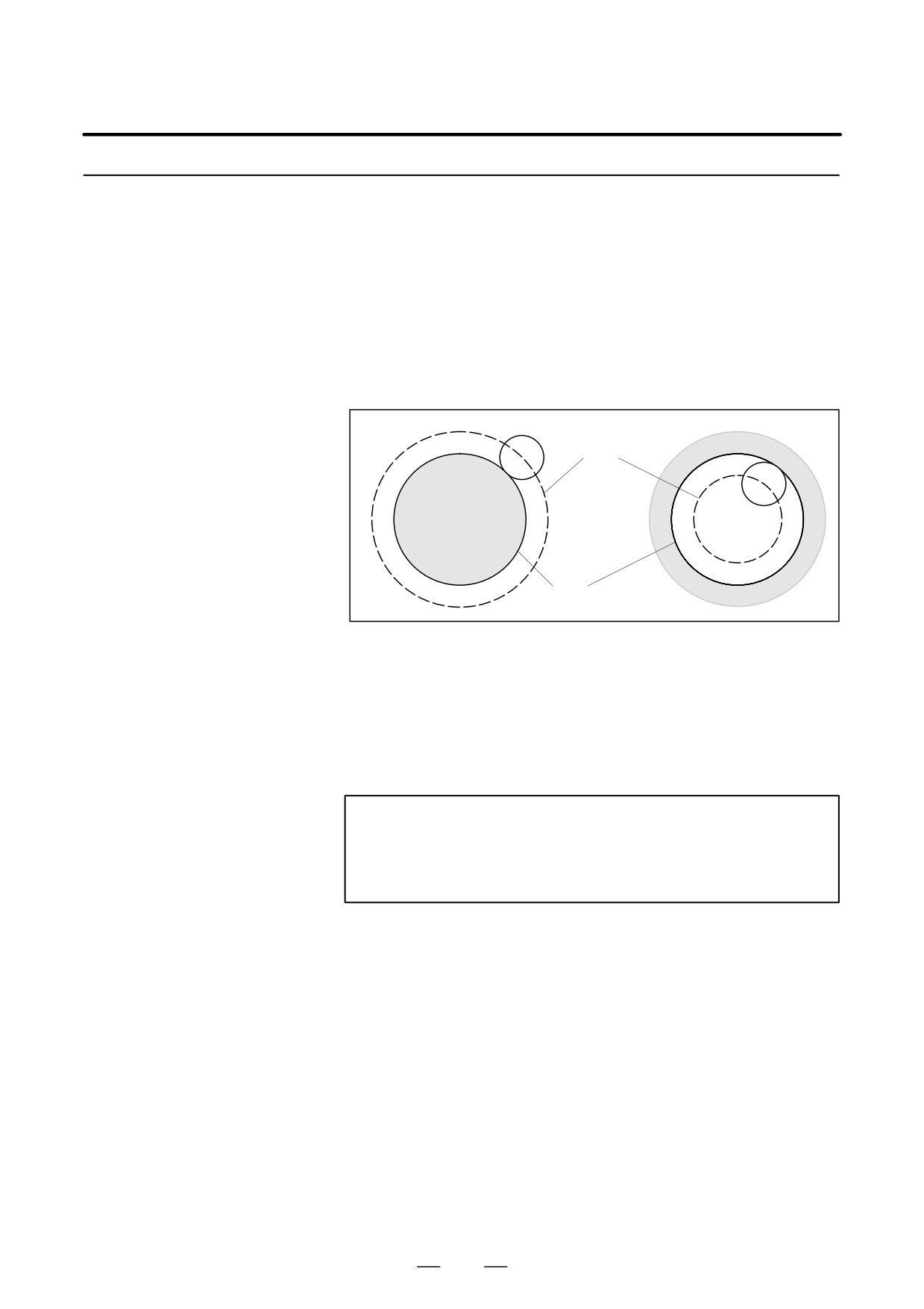
When the tool is moved, the tool path can be shifted by the radius of the
14.4
tool (Fig. 14.4).
CUTTER
To make an offset as large as the radius of the tool, first create an offset
COMPENSATION B
vector with a length equal to the radius of the tool (start-up). The offset
vector is perpendicular to the tool path. The tail of the vector is on the
(G39-G42)
workpiece side and the head points to the center of the tool.
If a linear interpolation, corner offset, or circular interpolation command
is specified after start-up, the tool path can be shifted by the length of the
offset vector during machining.
To return the tool to the start point at the end of machining, cancel the
cutter compensation mode.
Corner offset
Circular interpolation
Circular
interpolation
Linear interpolation
Corner offset
Circular
R1
interpolation
Linear
interpolation
R2
Offset vector
Start up
Circular
Linear
interpolation
interpolation
Cutter
Programmed path
ÇÇ
compensation
ÇÇ
cancel
Y axis
Tool center path
ÇÇ
Start position
X axis
Fig. 14.4 Outline of Cutter Compensation B
282
PROGRAMMING
14. COMPENSATION FUNCTION
B-63534EN/02
Format
D Start up
G00 (or G01) G41 (or G42)
IP_ IR_
H_ ;
(Cutter compensation
G41
: Cutter compensation left (Group 07)
start)
: Cutter compensation right (Group 07)
G42
IP
_
: Command for axis movement
IR_
: Incremental value from the end position. Perpendicular to the offset
vector at the end position.
H_
: Code for specifying the cutter compensation value (1 to 3 digits)
D Corner offset circular
G39
IP
(or
IR_)
;
interpolation
G39 : Corner offset circular interposition (Group 00)
: Incremental value from the end position. Perpendicular to
IP_ (or) IR_
the offset vector at the end position.
D Cutter compensation
G40IP_ ;
cancel
G40 : Cutter compensation cancel (Group 07)
IP_
: Command for axis movement
D Selection of the offset
Offset plane
Command of the plane selection
IP
_
IR_
plane
XpYp
G17 ;
Xp_Yp_
I_J_
ZpXp
G18 ;
Xp_Zp_
I_K_
YpZp
G19 ;
Yp_Zp_
J_K_
Explanations
D H code
Specify the number assigned to a cutter compensation value with a 1- to
3-digit number after address H (H code) in the program. The H code can
be specified in any position before the offset cancel mode is first switched
to the cutter compensation mode. The H code need not be specified again
unless the cutter compensation value needs to be changed.
Assign cutter compensation values to the H codes on the MDI panel. For
the specification of the cutter compensation value, see III-11.4.1 in the
section on operation.
The table below shows the range in which the cutter compensation values
can be specified.
Table 14.4 Valid range of cutter compensation values
Metric input
inch input
Cutter compensation value
0 to ±999.999mm
0 to ±99.9999inch
NOTE
The cutter compensation value corresponding to offset
No.0, that is, H0 always gets 0. It is impossible to set H0 to
any other cutter compensation value.
283
14. COMPENSATION FUNCTION
PROGRAMMING
B-63534EN/02
D Offset plane selection
Cutter compensation is carried out in the plane determined by G17, G18
and offset vector
and G19 (G codes for plane selection.). This plane is called the offset
plane. If the offset plane is not specified, G17 is assumed to be
programmed.
Compensation is not executed for the coordinates of a position which is
not in the specified plane. The programmed values are used as they are.
In the sequel, what vector is created, what offset calculation is made, by
an offset command, will be discussed on assumption that an XY plane is
selected. This discussion applies also when another plane is selected.
The offset vector is cleared by reset.
After the power is turned on, the length of the offset vector is set to zero
and the cutter compensation cancel mode is selected.
Notes
D Transition from the offset
cancel mode to the
cutter compensation
NOTE
mode (Start up)
A move command mode at the time of change from the
offset cancel mode to the cutter compensation mode, is
positioning (G00) or linear interpolation (G01). The circular
interpolation (G02, G03) cannot be used.
284
PROGRAMMING
14. COMPENSATION FUNCTION
B-63534EN/02
14.4.1
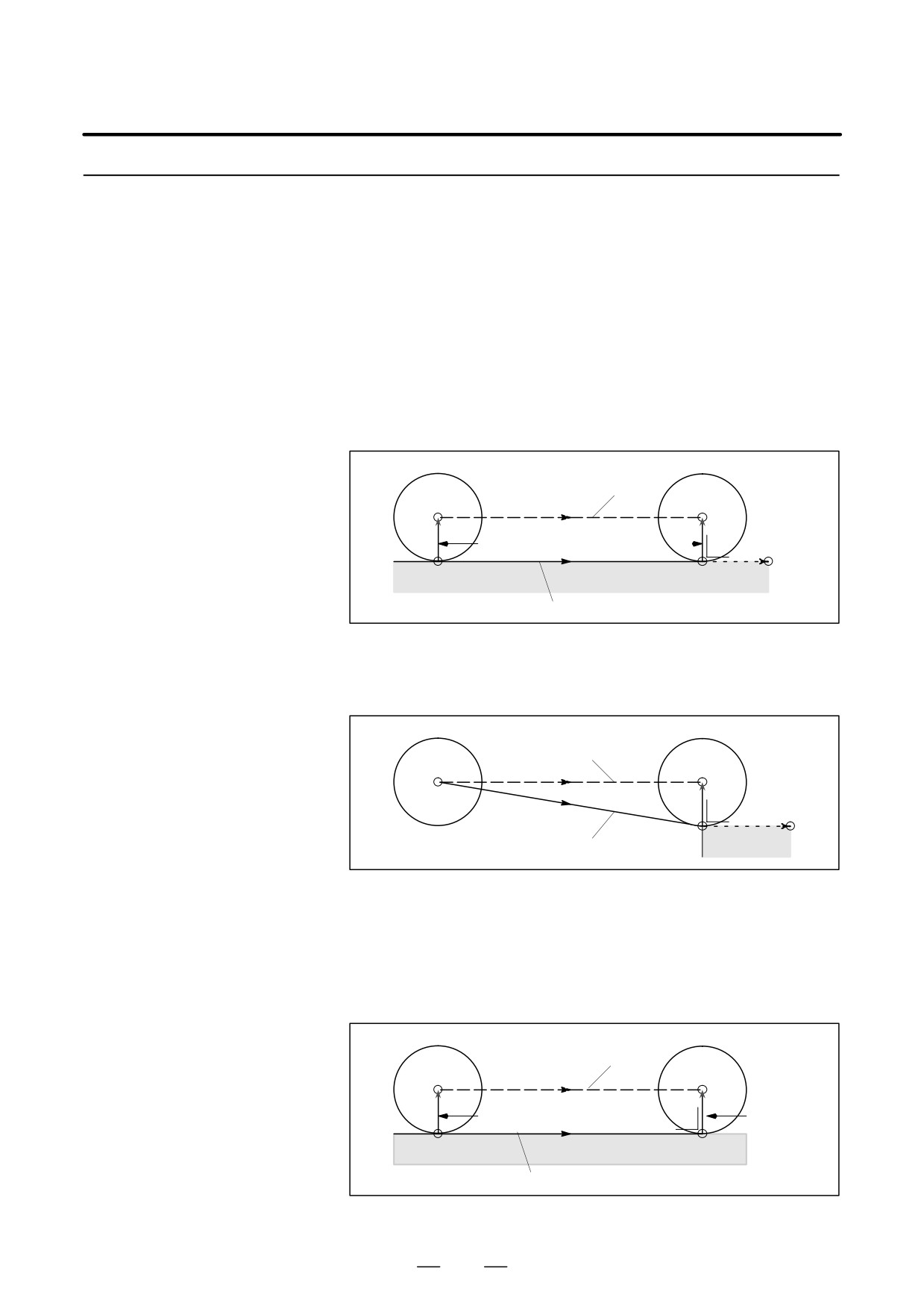
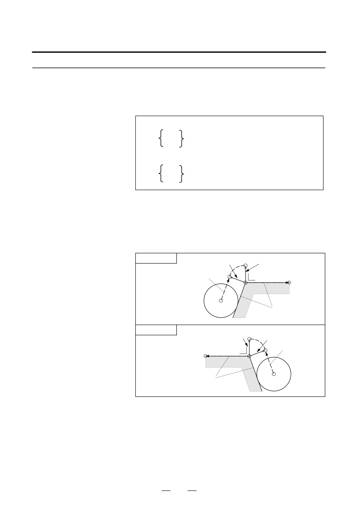
G41 offsets the tool towards the left of the workpiece as you see when you
face in the same direction as the movement of the cutting tool.
Cutter Compensation
Left (G41)
Explanations
D G00 (positioning) or
G41 X_ Y_ I_ J_ H_ ;
G01 (linear interpolation)
specifies a new vector to be created at right angles with the direction of
(I, J) on the end point, and the tool center moves toward the point of the
new vector from that of the old vector on the start point.(I, J) is expressed
in an incremental value from the end point, and is significant only as a
direction, and its amount is arbitrary.
ÇÇÇ
ÇÇÇ
Tool center path
ÇÇÇÇÇ
ÇÇÇÇÇ
ÇÇÇÇÇ
ÇÇÇÇÇ
Old vector
New vector ÇÇÇÇ
ÇÇÇÇÇ
ÇÇÇ
ÇÇÇ
Start
position
(X, Y)
(I, J)
Programmed path
In case the old vector is 0, this command specifies the equipment to enter
from the cancel mode into the cutter compensation mode. At this time,
the offset number is specified by the H code.
ÇÇ
ÇÇÇ
Tool center path
ÇStart position
ÇÇÇÇÇ
ÇÇÇÇÇ
ÇÇÇÇÇ
ÇÇÇÇÇ
ÇÇÇÇÇ
New vector
ÇÇÇ
ÇÇÇ
(X, Y)
(I, J)
Old vector=0
Programmed path
Unless otherwise specified, (I, J) are assumed to be equal to (X, Y). When
the following command is specified, a vector perpendicular to a line
connecting the start position and position (X, Y) is created.
G41 X_ Y_ ;
If, however, G00 is specified, each axis moves independently at the rapid
traverse rate.
ÇÇÇ
ÇÇÇ
Tool center path
ÇÇÇÇÇ
ÇÇÇÇÇ
ÇÇÇÇÇ
ÇÇÇÇÇ
ÇÇÇÇÇ
Old vector
ÇÇÇÇÇ
New vector
ÇÇÇ
ÇÇÇ
Start position
(X, Y)
Programmed path
285
14. COMPENSATION FUNCTION
PROGRAMMING
B-63534EN/02
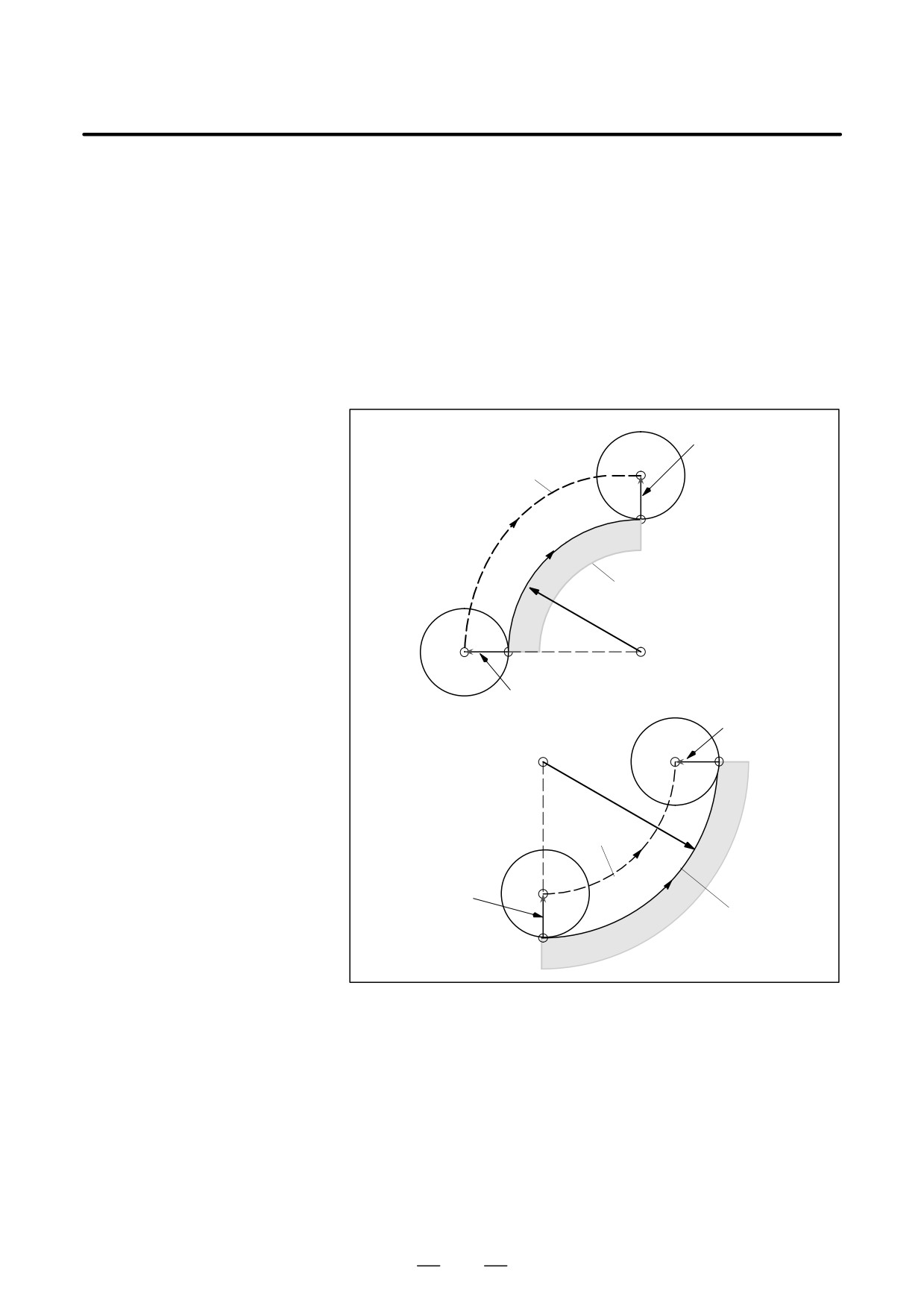
D G02, G03
G41… ;
(Circular interpolation)
:
G02 (or G03) X_ Y_ R_ ;
Above command specifies a new vector to be created to the left looking
toward the direction in which an arc advances on a line connecting the arc
center and the arc end point, and the tool center to move along the arc
advancing from the point of the old vector on the arc start point toward
that of the new vector. This is, however, established on assumption the
old vector is created correctly.
The offset vector is created toward the arc center or opposite direction
against the arc center.
New vector
ÇÇÇÇ
Tool center path
ÇÇÇÇ
ÇÇÇÇ
ÇÇÇÇ
(X, Y)
Programmed path
R
ÇÇÇ
ÇÇÇÇÇ
ÇÇÇÇÇ
Start position
ÇÇÇÇÇ
Old vector
ÇÇÇ
New vector
ÇÇÇÇ
(X, Y)
ÇÇÇÇÇ
R
ÇÇÇÇÇ
ÇÇÇÇ
Tool center path
ÇÇÇÇ
ÇÇÇÇ
Old vector
ÇÇÇÇ
Programmed path
ÇÇÇÇ
Start positionÇÇ
286
PROGRAMMING
14. COMPENSATION FUNCTION
B-63534EN/02
14.4.2
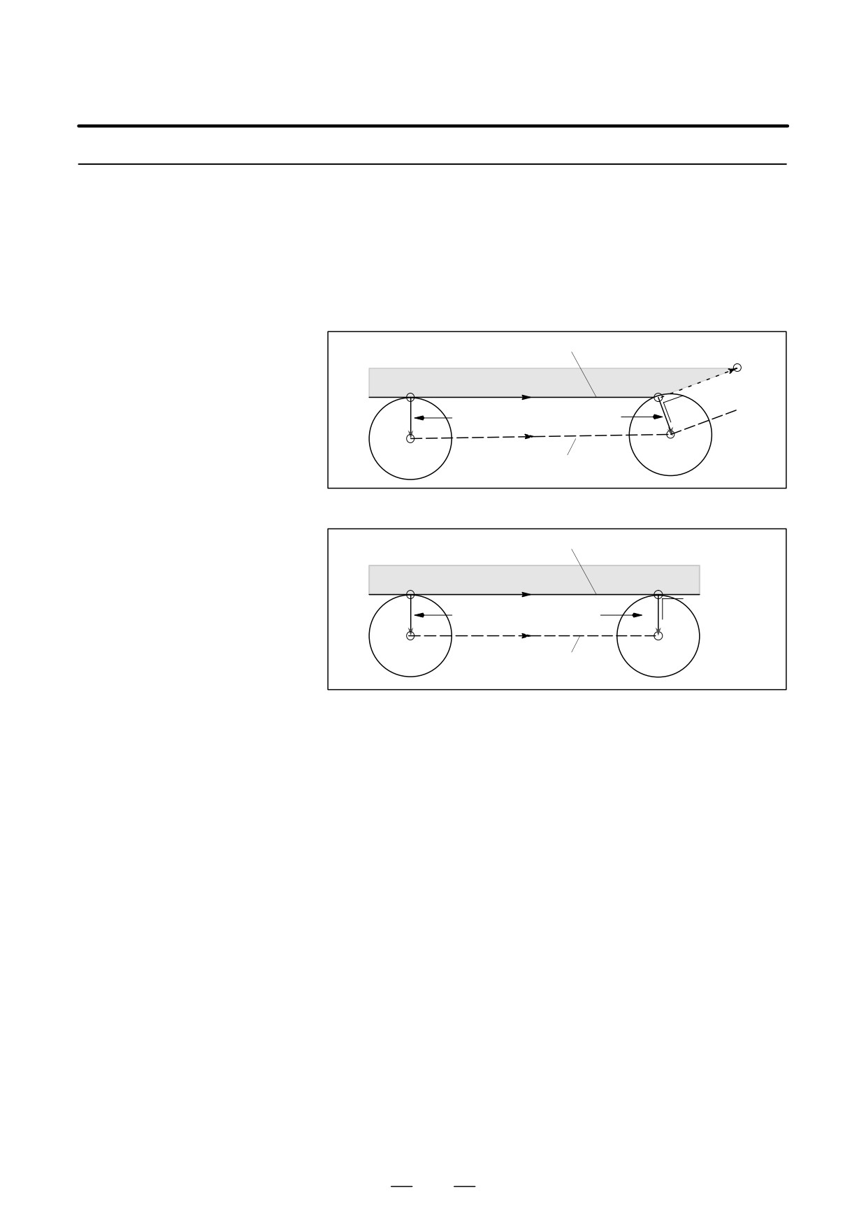
G42, contrary to G41, specifies a tool to be offset to the right of work piece
looking toward the direction in which the tool advances.
Cutter Compensation
G42 has the same function as G41, except that the directions of the vectors
Right (G42)
created by the commands are the opposite.
Explanations
D G00 (positioning) or
G42 X_ Y_ I_ J_ H_ ;
G01 (linear interpolation)
Programmed path
(I, J)
Start position
(X, Y)
ÇÇÇ
ÇÇÇÇ
Old vector
New vector
ÇÇÇÇÇ
ÇÇÇÇ
ÇÇÇÇÇ
ÇÇÇÇ
ÇÇÇÇÇ
Tool center path
ÇÇÇÇ
ÇÇÇ
ÇÇ
G42 X_ Y_ ;
Programmed path
(X, Y)
Start position
ÇÇÇ
ÇÇÇ
Old vector New vector
ÇÇÇÇÇ
ÇÇÇÇÇ
ÇÇÇÇÇ
ÇÇÇÇÇ
Tool center path
ÇÇÇÇÇ
ÇÇÇÇÇ
ÇÇÇ
ÇÇÇ
In the case of G00, however, each axis moves independently at the rapid
traverse rate.
287
14. COMPENSATION FUNCTION
PROGRAMMING
B-63534EN/02
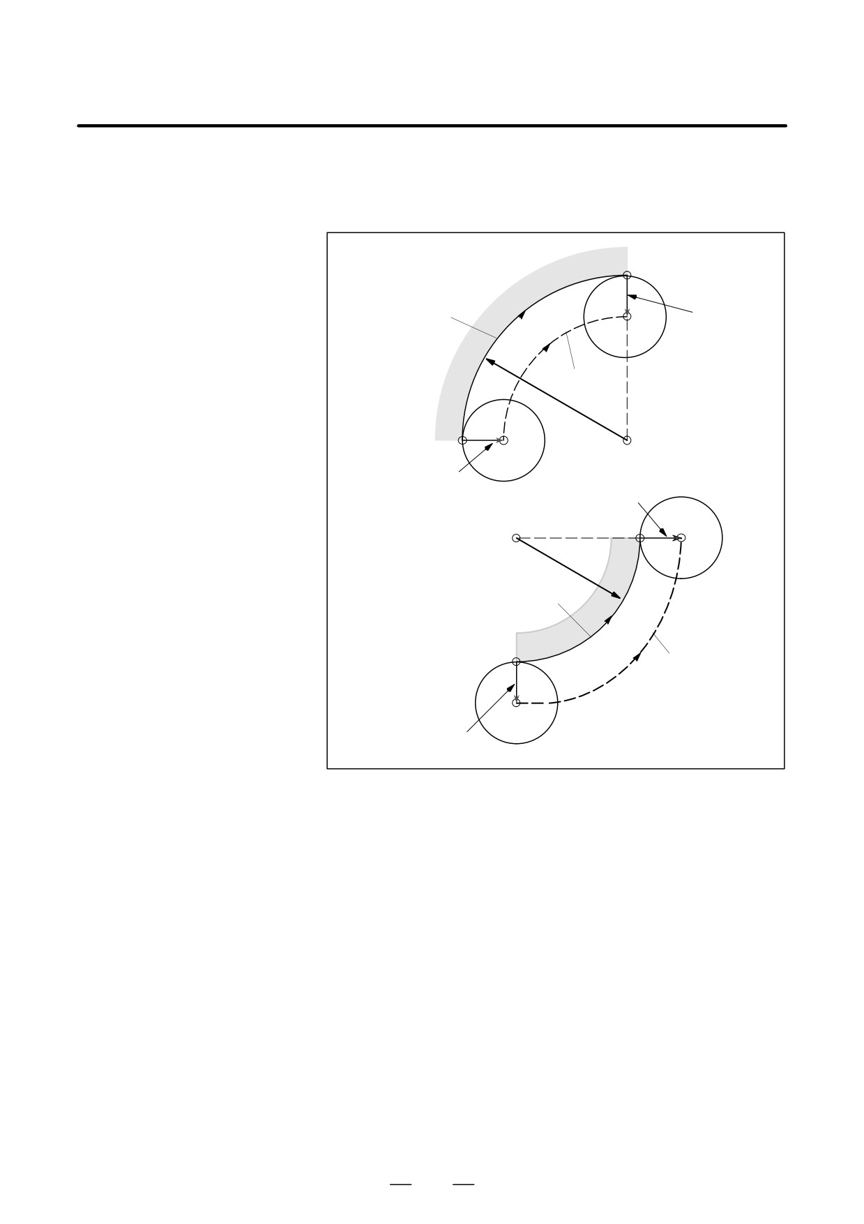
D G02 or G03
G42… ;
(Circular interpolation)
:
G02 (or G03) X_ Y_ R_;
(X, Y)
ÇÇÇÇ
Programmed path
ÇÇÇÇ
New vector
ÇÇÇÇ
ÇÇÇÇ
Tool center path
ÇÇÇ
R
ÇÇÇÇÇ
Start position
ÇÇÇÇÇ
ÇÇÇÇÇ
Old vectorÇÇÇ
New vector
ÇÇÇÇ
(X, Y)ÇÇÇÇÇ
R
ÇÇÇÇÇ
ÇÇÇÇÇ
Programmed path
Start position ÇÇ
Tool center path
ÇÇÇÇ
ÇÇÇÇ
ÇÇÇÇ
Old vector
ÇÇÇ
288
PROGRAMMING
14. COMPENSATION FUNCTION
B-63534EN/02
14.4.3
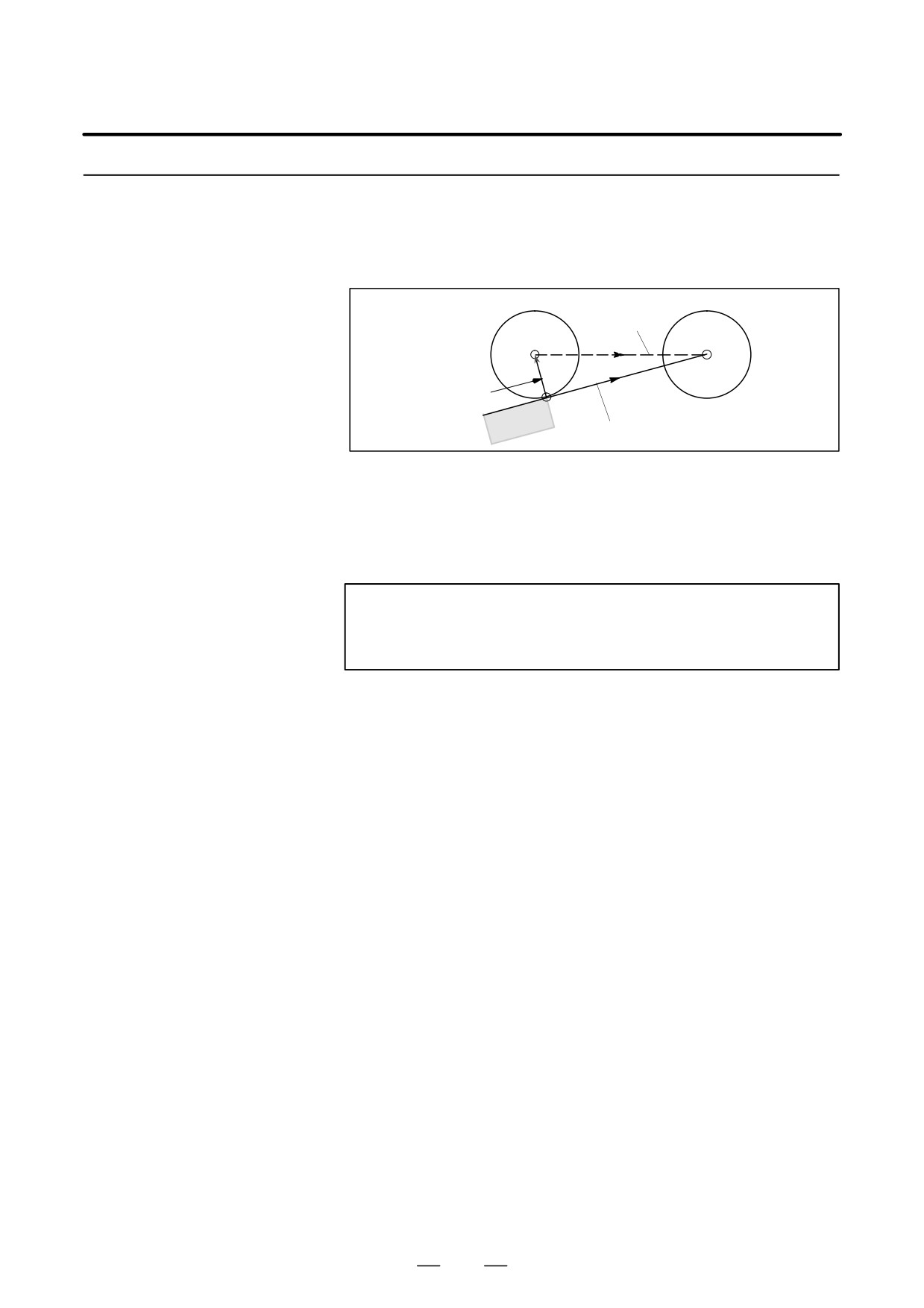
When the following command is specified in the G01, G02, or G03 mode,
corner offset circular interpolation can be executed with respect to the
Corner Offset Circular
radius of the tool.
Interpolation (G39)
Format
In offset mode
X_Y_
G39
X_Z_
;
Y_Z_
or
I_J_
G39
I_K_
;
J_K_
A new vector is created to the left (G41) or to the right (G42) looking
toward (X, Y) from the end point at right angles therewith, and the tool
moves along the arc from the point of the old vector toward that of the new
vector.
(X, Y, Z) is expressed in a value according to the G90/G91
respectively.
(I, J, K) is expressed in an incremental value from the end
point.
Case of G41
Old vector
New vector
Tool center path
(X, Y)or(I, J)
ÇÇÇ
ÇÇÇÇ
ÇÇÇÇ
Programmed path
ÇÇÇÇ
ÇÇÇ
Case of G42
New vector
Old vector
Tool center path
(X, Y)or(I, J)
ÇÇÇ
ÇÇÇÇÇ
ÇÇÇÇÇ
Programmed path
ÇÇÇÇÇ
ÇÇÇ
This command can be given in offset mode, that is, only when G41 or G42
has already been specified. Whether the arc is to turn clockwise or
counterclockwise, is defined by G41 or G42, respectively. This command
is not modal, and executes circular interpolation, whatever the G function
of group 01 may be. The G function of group 01 remains even though this
command is specified.
289
14. COMPENSATION FUNCTION
PROGRAMMING
B-63534EN/02
14.4.4
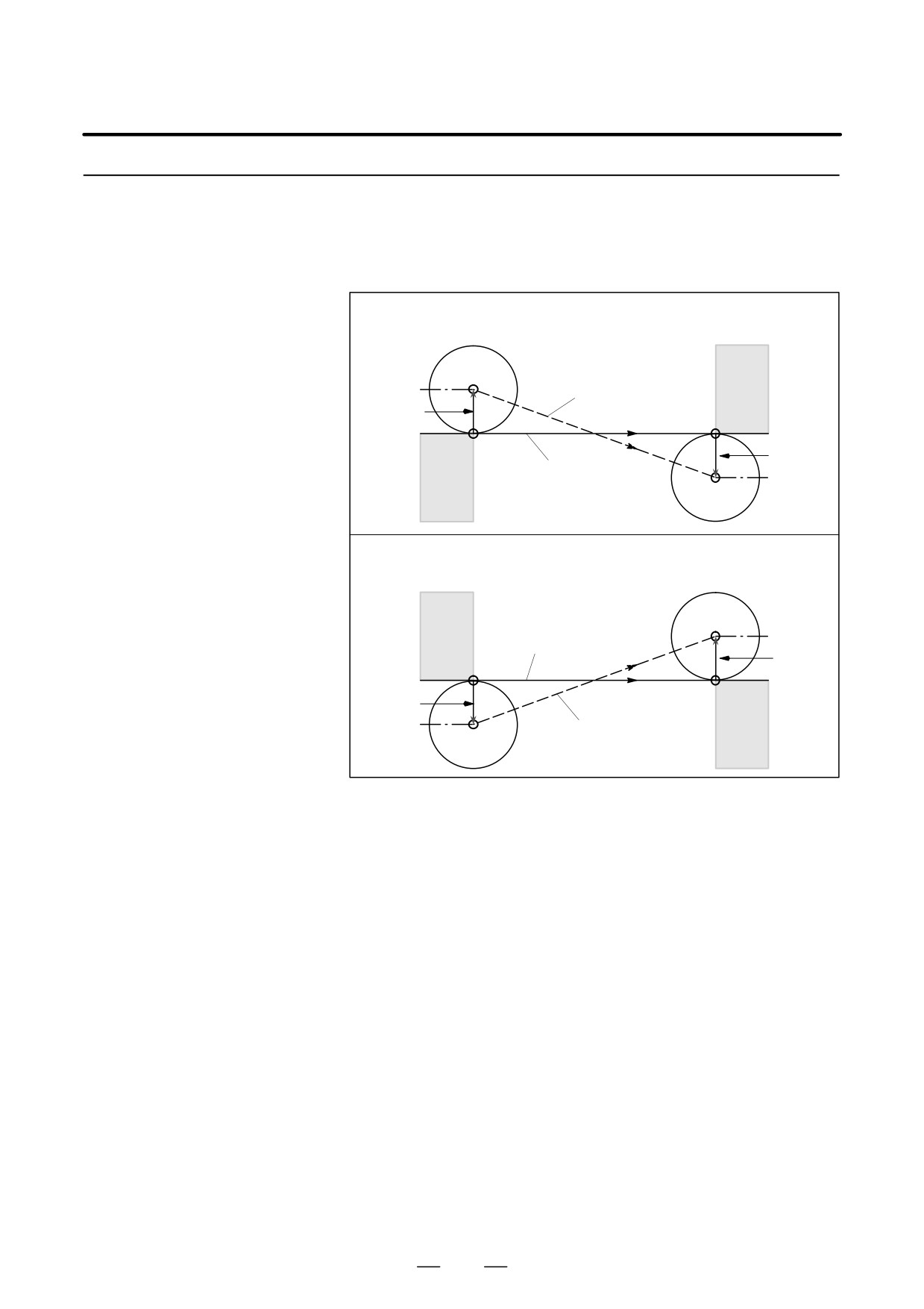
When the following command is specified in the G00 or G01 mode, the
tool moves from the head of the old vector at the start position to the end
Cutter Compensation
position (X, Y). In the G01 mode, the tool moves linearly. In the G00
Cancel (G40)
mode, rapid traverse is carried out along each axis.
G40 X_ Y_ ;
Tool center path
ÇÇÇÇÇ ÇÇÇÇÇ
ÇÇÇÇÇ ÇÇÇÇÇ
(X, Y)
ÇÇÇÇÇ ÇÇ
Old vector
ÇÇÇÇ
ÇÇÇÇ
Start position
Programmed path
This command changes the mode of the equipment from the cutter
compensation mode to the cancel mode.
When only G40; is specified, and X _ Y _ is not specified, the tool moves
by the old vector amount in the opposite direction.
NOTE
Cutter compensation cannot be canceled in the circular
interpolation (G02, G03) mode.
290
PROGRAMMING
14. COMPENSATION FUNCTION
B-63534EN/02
14.4.5
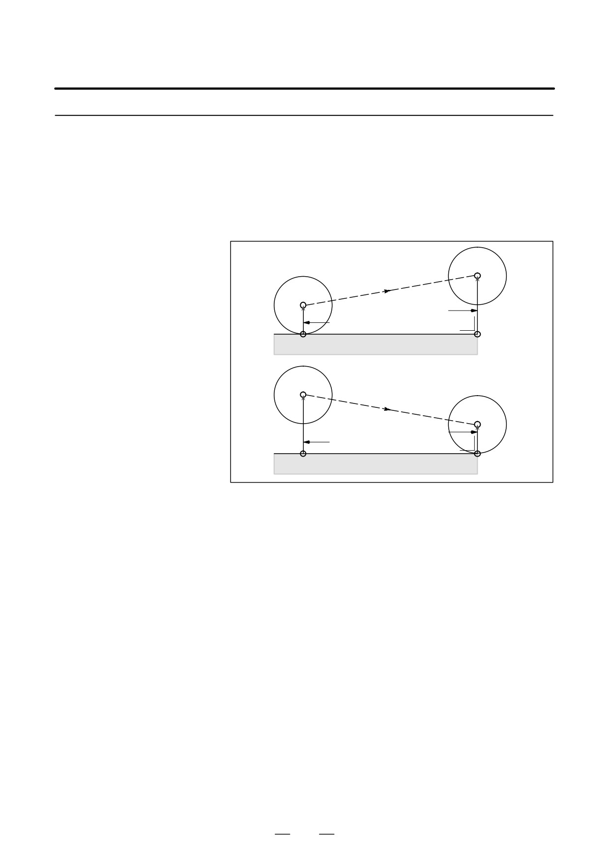
The offset direction is switched from left to right, or from right to left
generally through the offset cancel mode, but can be switched not through
Switch between Cutter
it only in positioning (G00) or linear interpolation (G01). In this case, the
Compensation Left and
tool path is as shown in Fig 14.4.5.
Cutter Compensation
Right
G41……… ;
G00 G42 X_ Y_ ;
ÇÇÇÇ
ÇÇÇÇ
Tool center path
(normally, it is not straight.)
ÇÇÇÇÇ
Old vector
(X, Y)
ÇÇÇÇ
Ç
ÇÇÇÇ
New
vector
Programmed path
ÇÇÇÇ
ÇÇÇÇ
ÇÇÇÇ
G42……… ;
G00 G41 X_ Y_ ( or I_ J_) F_ ;
ÇÇ
ÇÇÇÇ
Tool center path
ÇÇÇÇ
New
ÇÇÇÇ
vector
ÇÇÇÇ
ÇÇÇÇ
(X, Y)or(I, J)
Old vector
ÇÇÇÇ
Programmed path
ÇÇÇÇÇ
ÇÇÇÇ
ÇÇ
Fig. 14.4.5 Switching the Direction of Cutter Compensation
291
14. COMPENSATION FUNCTION
PROGRAMMING
B-63534EN/02
14.4.6
The offset amount is changed generally when the tool is changed in the
offset cancel mode, but can be changed in the offset mode only in
Change of the Cutter
positioning (G00) or linear interpolation (G01).
Compensation Value
Program as described below:
G00 (or G01) X_ Y_ H_ ; (H_ indicates the number of a new cutter
compensation value.)
Fig.
14.4.6 shows how the tool is moved when the change in
compensation is specified.
ÇÇÇ
ÇÇÇÇÇ
Tool center path
ÇÇÇ
ÇÇÇÇÇ
ÇÇÇÇÇ
ÇÇÇÇÇ
New vector
ÇÇÇÇÇ
ÇÇÇ
Old vector
ÇÇÇÇÇ
Start position
Programmed path
(X, Y)
ÇÇÇÇ
ÇÇÇÇÇ
ÇÇÇÇÇ
ÇÇÇÇ
ÇÇÇÇ
ÇÇÇÇÇ
New vector
Old vector
ÇÇÇÇÇ
ÇÇÇÇ
Programmed path
Start position
(X, Y)
Fig 14.4.6 Change of the cutter compensation value in offset mode
292
PROGRAMMING
14. COMPENSATION FUNCTION
B-63534EN/02
14.4.7
If the tool compensation value is made negative (-), it is equal that G41
and G42 are replaced with each other in the process sheet. Consequently,
Positive/Negative
if the tool center is passing around the outside of the workbench it will
Cutter Compensation
pass around the inside thereof, and vice versa.
Value and Tool Center
Fig.
14.4.7 shows one example. Generally speaking, the cutter
Path
compensation value shall be programmed to be positive (+). When a tool
path is programmed as shown in (1), if the cutter compensation value is
made negative (-), the tool center moves as shown in (2).
If the cutter compensation value is changed to a negative value when tool
path (2) shown in Fig. 14.4.7 is programmed, the tool follows tool path
(1) shown in the same figure.
(1)
(2)
ÇÇÇ
Tool center path
ÇÇÇ
ÇÇ
ÇÇ
ÇÇ
ÇÇ
Programmed path
Fig. 14.4.7 Tool Center Paths when Positive and Negative
Cutter Compensation Values are Specified
For a cornered figure (involved in corner circular interpolation) in
general, the cutter compensation value naturally cannot be made negative
(-) to cut the inside. In order to cut the inside corner of a cornered figure,
an arc with an appropriate radius must be inserted there to provide smooth
cutting.
WARNING
If the tool length offset is commanded during cutter
compensation, the offset amount of cutter compensation is
also regarded to have been changed.
293
14. COMPENSATION FUNCTION
PROGRAMMING
B-63534EN/02
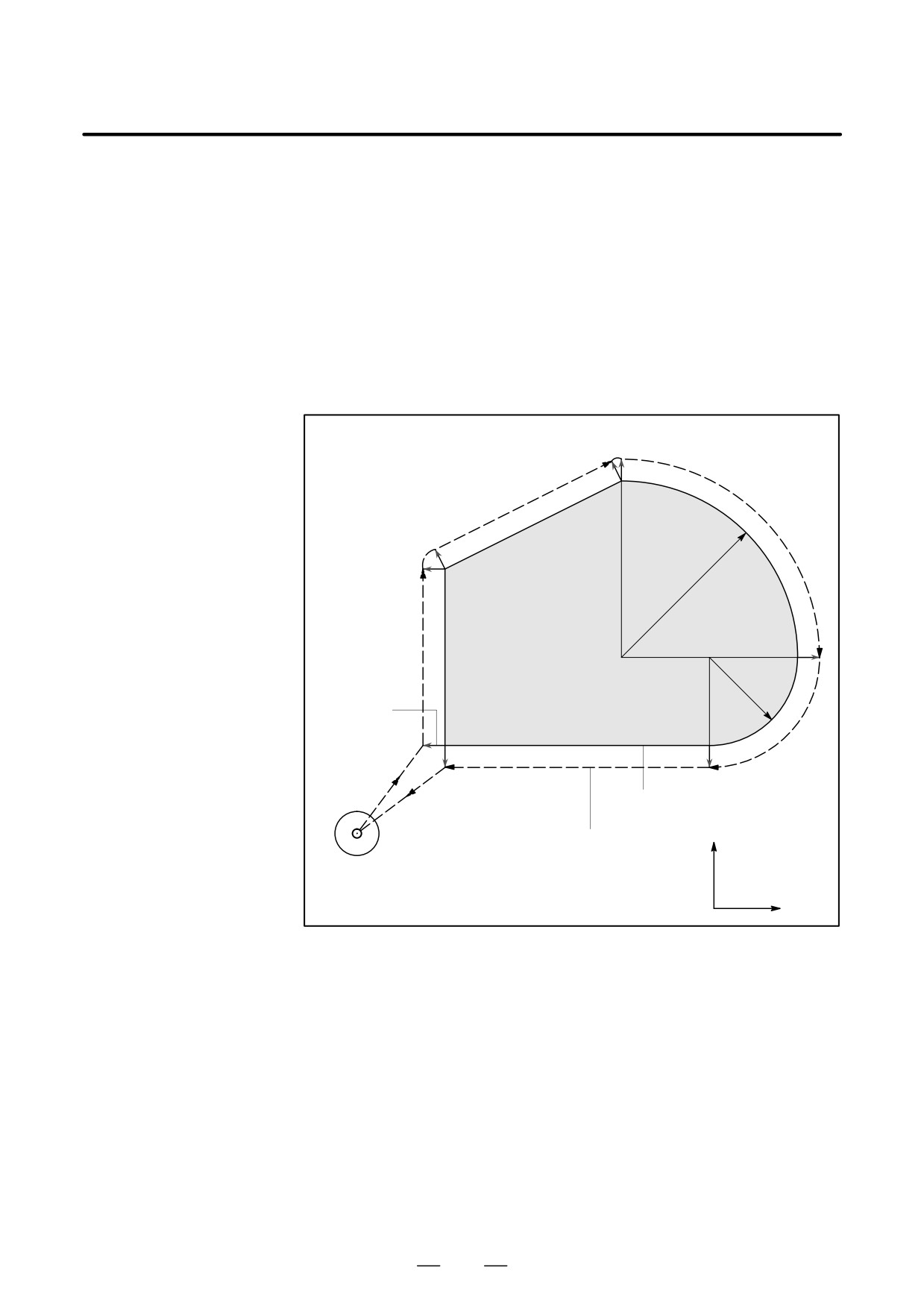
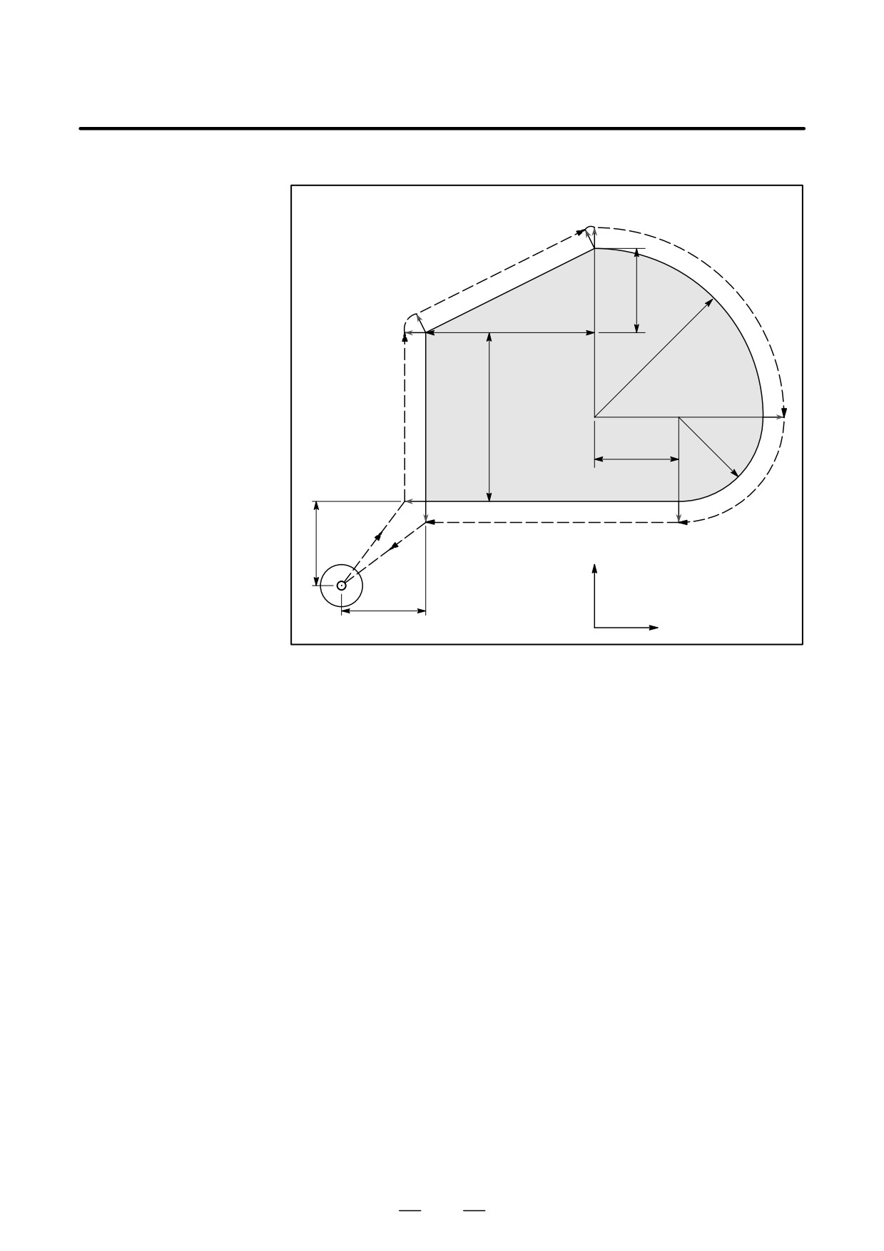
Examples
N6
N5
20.0
N7
40.0
N4
R1=40.0
40.0
N3
R2=20.0
20.0
N2
N8
N10
N9
20.0
N1
Y axis
ÇÇ
N11
ÇÇ
ÇÇ
20.0
X axis
Unit : mm
N1 G91 G17 G00 G41 J1 X20.0 Y20.0 H08 ;
N2 G01 Z-25.0 F100 ;
N3 Y40.0 F250 ;
N4 G39 I40.0 J20.0 ;
N5 X40.0 Y20.0 ;
N6 G39 I40.0 ;
N7 G02 X40.0 Y-40.0 R40.0 ;
N8 X-20.0 Y-20.0 R20.0 ;
N9 G01 X-60.0 ;
N10 G00 Z25.0 ;
N11 G40 X-20.0 Y-20.0 M02 ;
(H08 is a tool offset number, and the cutter radius value should be stored in the
memory corresponding to this number).
294
PROGRAMMING
14. COMPENSATION FUNCTION
B-63534EN/02
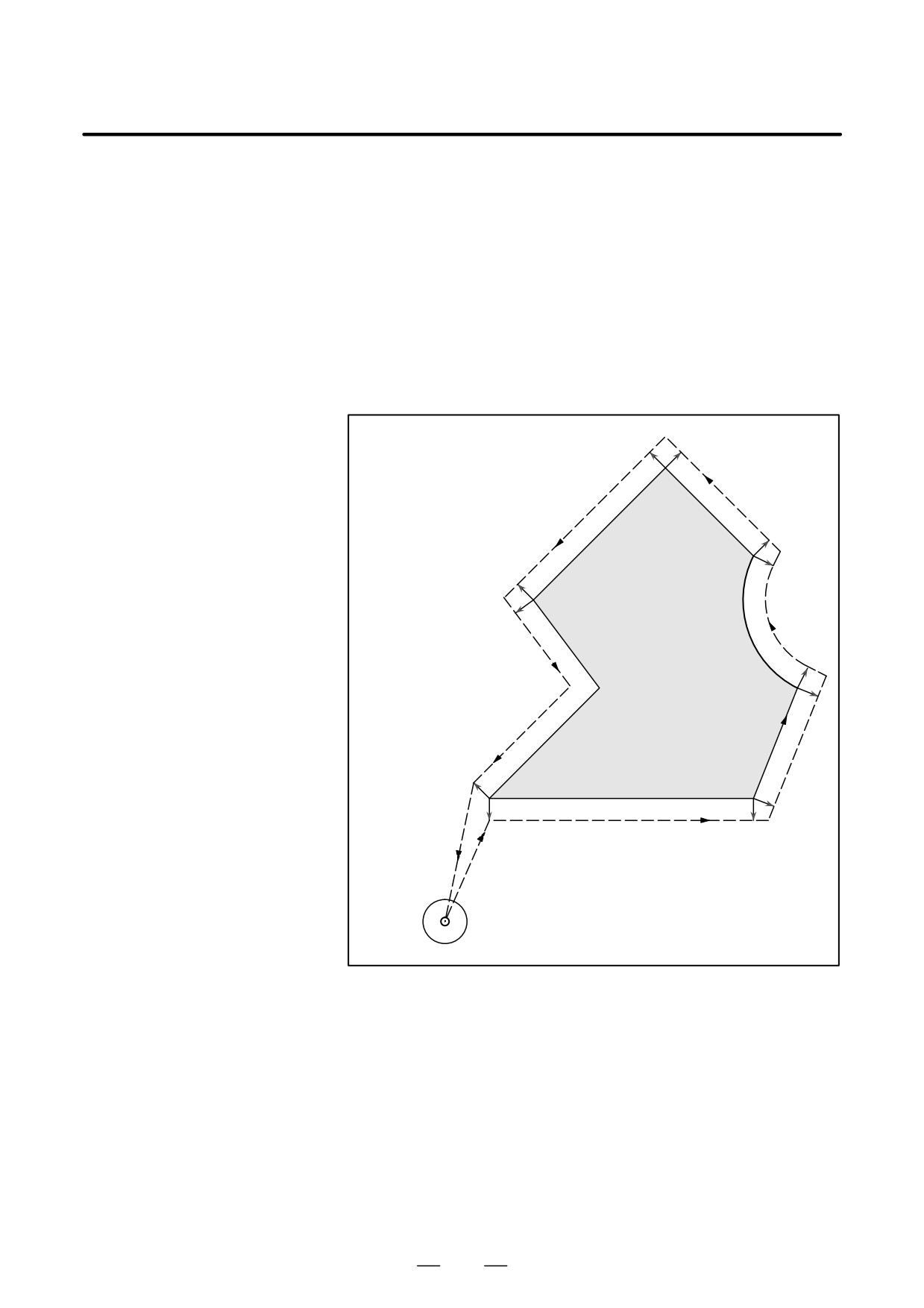
When the tool is moved, the tool path can be shifted by the radius of the
14.5
tool (Fig. 14.5 (a)).
OVERVIEW OF
To make an offset as large as the radius of the tool, CNC first creates an
CUTTER
offset vector with a length equal to the radius of the tool (start-up). The
offset vector is perpendicular to the tool path. The tail of the vector is on
COMPENSATION C
the workpiece side and the head positions to the center of the tool.
(G40-G42)
If a linear interpolation or circular interpolation command is specified
after start-up, the tool path can be shifted by the length of the offset vector
during machining.
To return the tool to the start position at the end of machining, cancel the
cutter compensation mode.
Cutter
compensation
cancel
Start-up
ÇÇÇ
ÇÇÇ
ÇÇÇ
Fig. 14.5 (a) Outline of Cutter Compensation C
295
14. COMPENSATION FUNCTION
PROGRAMMING
B-63534EN/02
Format
D Start up
G00(or G01)G41(or G42)
IP_ D_ ;
(Tool compensation
G41
: Cutter compensation left (Group07)
start)
G42
: Cutter compensation right (Group07)
IP_
: Command for axis movement
D_
: Code for specifying as the cutter compensation value(1-3digits)
(D code)
D Cutter compensation
;
G40
cancel
(offset mode cancel)
G40 : Cutter compensation cancel(Group 07)
(Offset mode cancel)
IP_
: Command for axis movement
D Selection of the offset
Offset plane
Command for plane selection
IP_
plane
XpYp
G17 ;
Xp_Yp_
ZpXp
G18 ;
Xp_Zp_
YpZp
G19 ;
Yp_Zp_
Explanations
D Offset cancel mode
At the beginning when power is applied the control is in the cancel mode.
In the cancel mode, the vector is always 0, and the tool center path
coincides with the programmed path.
D Start Up
When a cutter compensation command (G41 or G42, nonzero dimension
words in the offset plane, and D code other than D0) is specified in the
offset cancel mode, the CNC enters the offset mode.
Moving the tool with this command is called start-up.
Specify positioning (G00) or linear interpolation (G01) for start-up. If
circular interpolation (G02, G03) is specified, P/S alarm 34 occurs.
When processing the start-up block and subsequent blocks, the CNC
prereads two blocks.
D Offset mode
In the offset mode, compensation is accomplished by positioning (G00),
linear interpolation (G01), or circular interpolation (G02, G03). If two or
more blocks that do not move the tool (miscellaneous function, dwell,
etc.) are processed in the offset mode, the tool will make either an
excessive or insufficient cut. If the offset plane is switched in the offset
mode, P/S alarm 37 occurs and the tool is stopped.
296
PROGRAMMING
14. COMPENSATION FUNCTION
B-63534EN/02
D Offset mode cancel
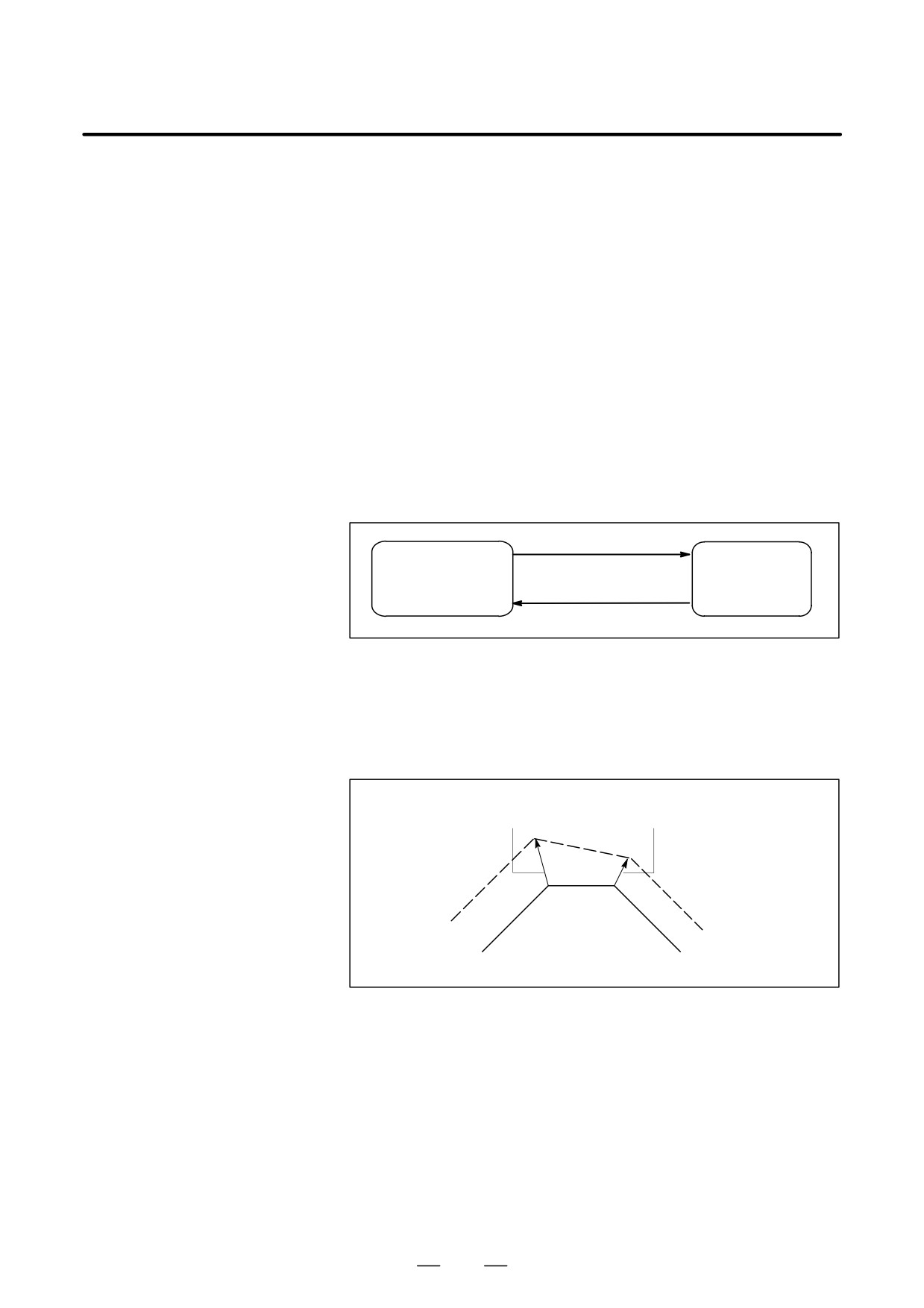
In the offset mode, when a block which satisfies any one of the following
conditions is executed, the CNC enters the offset cancel mode, and the
action of this block is called the offset cancel.
1. G40 has been commanded.
2. 0 has been commanded as the offset number for cutter
compensation.
When performing offset cancel, circular arc commands (G02 and G03) are
not available. If a circular arc is commanded, an P/S alarm (No. 034) is
generated and the tool stops.
In the offset cancel, the control executes the instructions in that block and
the block in the cutter compensation buffer. In the meantime, in the case
of a single block mode, after reading one block, the control executes it and
stops. By pushing the cycle start button once more, one block is executed
without reading the next block.
Then the control is in the cancel mode, and normally, the block to be
executed next will be stored in the buffer register and the next block is not
read into the buffer for cutter compensation.
Start up
(G41/G42)
Offset cancel mode
Offset mode
Offset modecancel
(G40/D0)
Fig. 14.5 (b) Changing the offset mode
D Change of the Cutter
In general, the cutter compensation value shall be changed in the cancel
compensation value
mode, when changing tools. If the cutter compensation value is changed
in offset mode, the vector at the end point of the block is calculated for
the new cutter compensation value.
Calculated from the cutter
Calculated from the cutter
compensation value in the block
compensation value in the block N7
N6
N7
N8
N6
Programmed path
Fig. 14.5 (c) Changing the Cutter Compensation Value
297
14. COMPENSATION FUNCTION
PROGRAMMING
B-63534EN/02
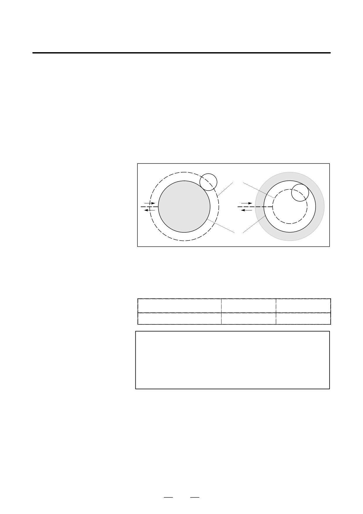
D Positive/negative cutter
If the offset amount is negative (-), distribution is made for a figure in
compensation value and
which G41’s and G42’s are all replaced with each other on the program.
tool center path
Consequently, if the tool center is passing around the outside of the
workpiece, it will pass around the inside, and vice versa.
The figure below shows one example. Generally, the offset amount is
programmed to be positive (+).
When a tool path is programmed as in ((1)), if the offset amount is made
negative
(-), the tool center moves as in
((2)), and vice versa.
Consequently, the same tape permits cutting both male and female
shapes, and any gap between them can be adjusted by the selection of the
offset amount. Applicable if start-up and cancel is A type. (See II- 14.6.2
and 14.6.4)
(1)
(2)
ÇÇÇ
Tool center path
ÇÇÇ
ÇÇ
ÇÇ
ÇÇ
ÇÇ
Programmed path
Fig. 14.5 (d) Tool Center Paths when Positive and Negative
Cutter Compensation Values are Specified
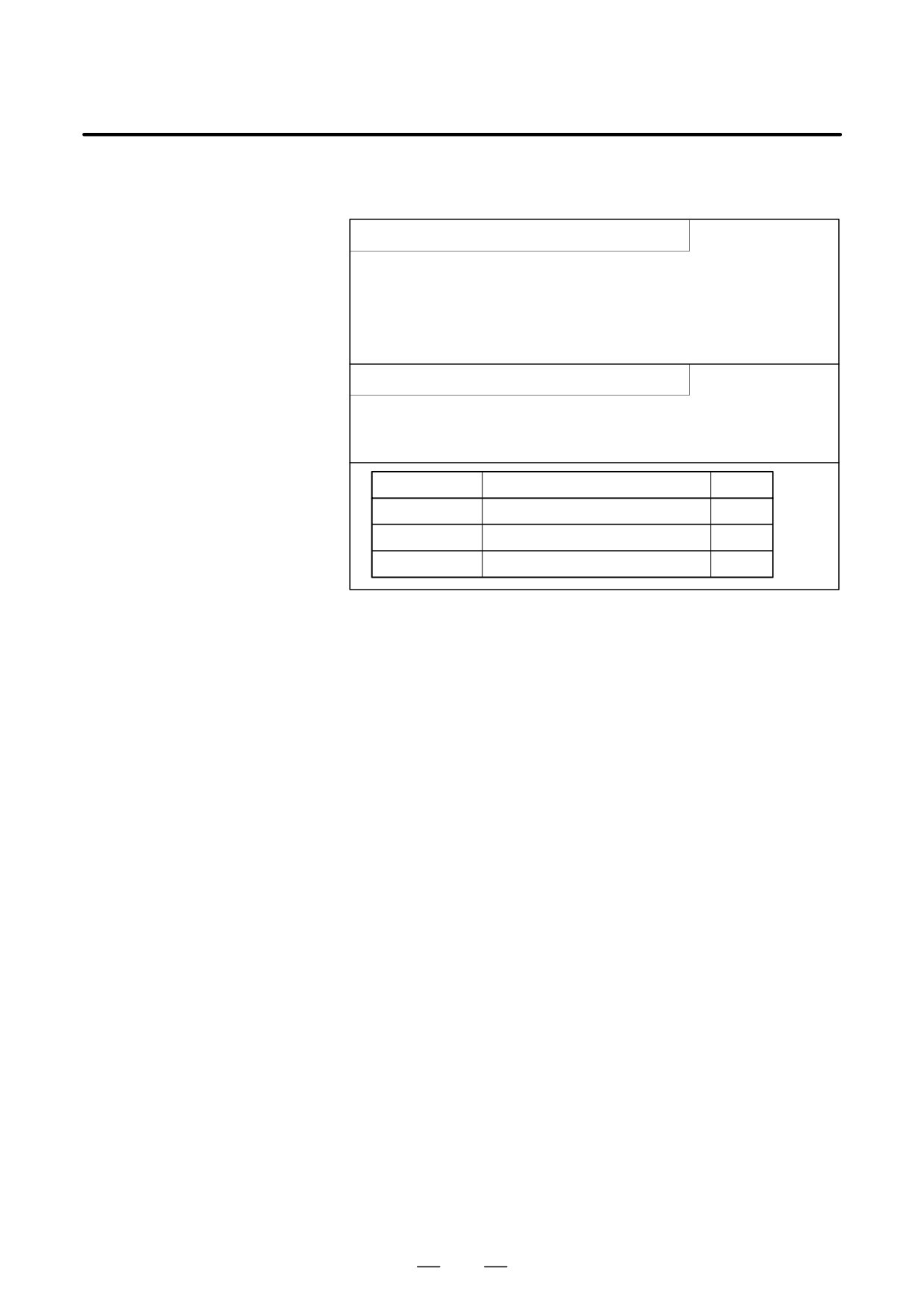
D Cutter compensation
Assign a cutter compensation values to the D codes on the MDI panel.
value setting
The table below shows the range in which cutter compensation values can
be specified.
mm input
inch input
Cutter compensation value
0 to ±999.999mm
0 to ±99.9999inch
NOTE
1
The cutter compensation value corresponding to offset No.
0, that is, D0 always means 0. It is impossible to set D0 to
any other offset amount.
2
Cutter compensation C can be specified by H code with
parameter OFH (No. 5001 #2) set to 1.
D Offset vector
The offset vector is the two dimensional vector that is equal to the cutter
compensation value assigned by D code. It is calculated inside the control
unit, and its direction is up-dated in accordance with the progress of the
tool in each block.
The offset vector is deleted by reset.
D Specifying a cutter
Specify a cutter compensation value with a number assigned to it. The
compensation value
number consists of 1 to 3 digits after address D (D code). The D code is
valid until another D code is specified. The D code is used to specify the
tool offset value as well as the cutter compensation value.
298
PROGRAMMING
14. COMPENSATION FUNCTION
B-63534EN/02
D Plane selection and
Offset calculation is carried out in the plane determined by G17, G18 and
vector
G19, (G codes for plane selection). This plane is called the offset plane.
Compensation is not executed for the coordinate of a position which is not
in the specified plane. The programmed values are used as they are.
In simultaneous 3 axes control, the tool path projected on the offset plane
is compensated.
The offset plane is changed during the offset cancel mode. If it is
performed during the offset mode, a P/S alarm (No. 37) is displayed and
the machine is stopped.
299
14. COMPENSATION FUNCTION
PROGRAMMING
B-63534EN/02
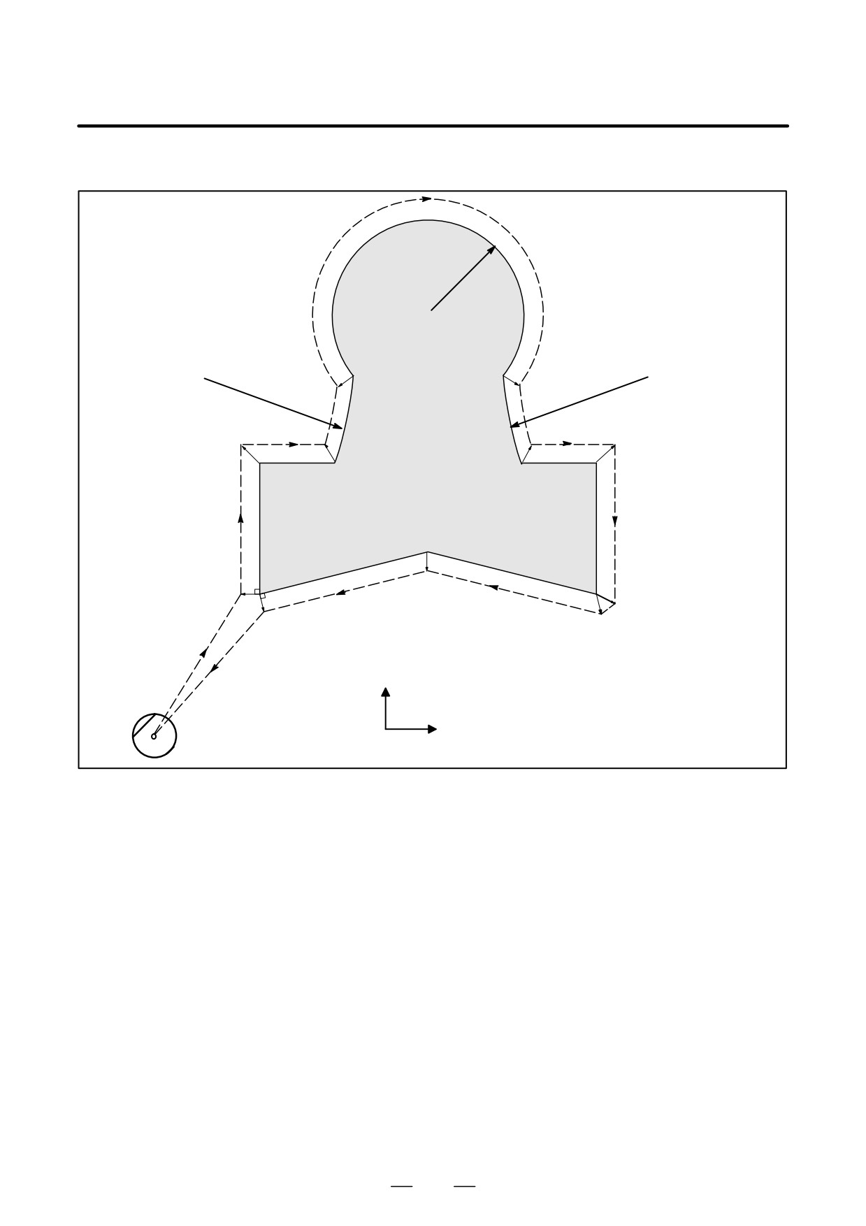
Examples
N5
250R
C1(700,1300)
C3 (-150,1150)
P4(500,1150) P5(900,1150)
C2 (1550,1550)
650R
650R
N4
N6
N3
N7
P3(450,900)
P2
P6(950,900)
P7
(1150,900)
(250,900)
N8
N2
P9(700,650)
P8
P1
(1150,550)
(250,550)
N10
N9
N1
Y axis
N11
ÇÇ
Unit : mm
X axis
ÇÇÇ
Start position
ÇÇÇ
G92 X0 Y0 Z0 ;
Specifies absolute coordinates.
The tool is positioned at the start position (X0, Y0, Z0).
N1 G90 G17 G00 G41 D07 X250.0 Y550.0 ; Starts cutter compensation (start-up). The tool is shifted to the
left of the programmed path by the distance specified in D07.
In other words the tool path is shifted by the radius of the tool
(offset mode) because D07 is set to 15 beforehand (the radius of
the tool is 15 mm).
N2 G01 Y900.0 F150 ;
Specifies machining from P1 to P2.
N3 X450.0 ;
Specifies machining from P2 to P3.
N4 G03 X500.0 Y1150.0 R650.0 :
Specifies machining from P3 to P4.
N5 G02 X900.0 R-250.0 ;
Specifies machining from P4 to P5.
N6 G03 X950.0 Y900.0 R650.0 ;
Specifies machining from P5 to P6.
N7 G01 X1150.0 ;
Specifies machining from P6 to P7.
N8 Y550.0 ;
Specifies machining from P7 to P8.
N9 X700.0 Y650.0 ;
Specifies machining from P8 to P9.
N10 X250.0 Y550.0 ;
Specifies machining from P9 to P1.
N11 G00 G40 X0 Y0 ;
Cancels the offset mode.
The tool is returned to the start position (X0, Y0, Z0).
300
PROGRAMMING
14. COMPENSATION FUNCTION
B-63534EN/02
This section provides a detailed explanation of the movement of the tool
14.6
for cutter compensation C outlined in Section 14.5.
DETAILS OF CUTTER
This section consists of the following subsections:
COMPENSATION C
14.6.1
General
14.6.2 Tool Movement in Start-up
14.6.3 Tool Movement in Offset Mode
14.6.4 Tool Movement in Offset Mode Cancel
14.6.5 Interference Check
14.6.6 Over cutting by Cutter Compensation
14.6.7
Input command from MDI
14.6.8
G53,G28,G30 and G29 commands in cutter
compensation C mode
14.6.9
Corner Circular Interpolation (G39)
14.6.1
General
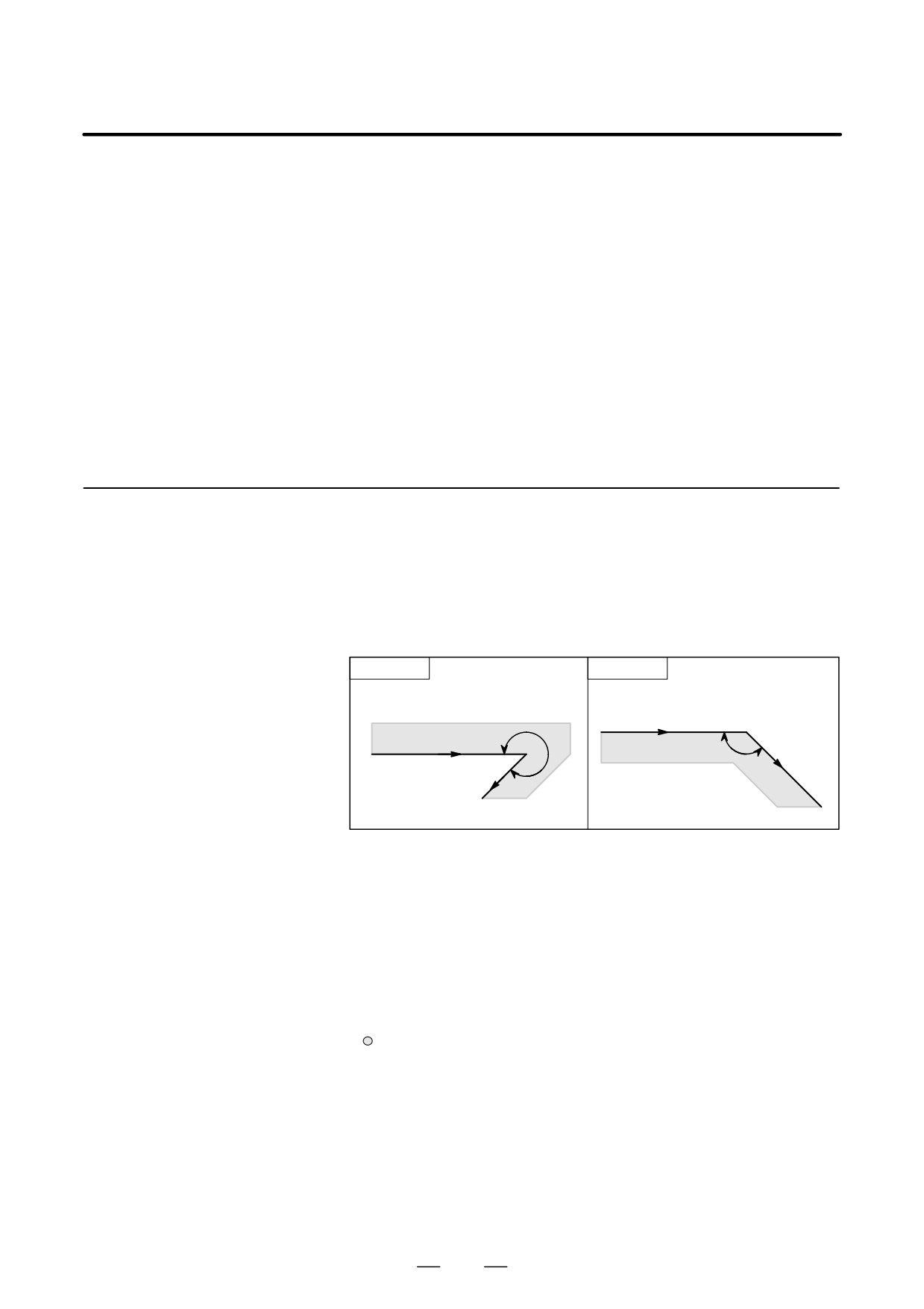
D Inner side and outer side
When an angle of intersection created by tool paths specified with move
commands for two blocks is over 180°, it is referred to as “inner side.”
When the angle is between 0° and 180°, it is referred to as “outer side.”
Inner side
Outer side
Programmed path
Workpiece
α
α
Workpiece
Programmed path
180°xα
0°xα<180°
D Meaning of symbols
The following symbols are used in subsequent figures:
- S indicates a position at which a single block is executed once.
- SS indicates a position at which a single block is executed twice.
- SSS indicates a position at which a single block is executed three times.
- L indicates that the tool moves along a straight line.
- C indicates that the tool moves along an arc.
- r indicates the cutter compensation value.
- An intersection is a position at which the programmed paths of two
blocks intersect with each other after they are shifted by r.
- indicates the center of the tool.
301
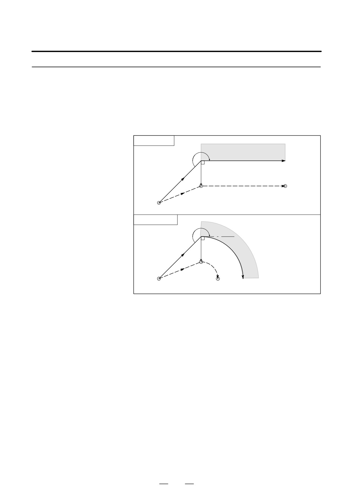
14. COMPENSATION FUNCTION
PROGRAMMING
B-63534EN/02
14.6.2
When the offset cancel mode is changed to offset mode, the tool moves
as illustrated below (start-up):
Tool Movement in
Start-up
Explanations
D Tool movement around
an inner side of a corner
Linear→Linear
(180°xα)
α
Workpiece
Programmed path
r
G42
S
L
Tool center path
L
Start position
Linear→Circular
α
Work-
r
G42
piece
S
C
L
Start
position
Tool center path
302
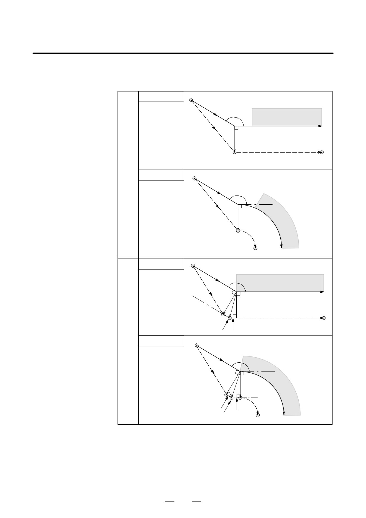
PROGRAMMING
14. COMPENSATION FUNCTION
B-63534EN/02
D Tool movement around
Tool path in start-up has two types A and B, and they are selected by
the outside of a corner at
parameter SUP (No. 5003#0).
an obtuse angle
(90°xα<180°)
Linear→Linear
Start position
G42
α
Workpiece
L
Programmed path
r
S
L
Tool center path
Type
A
Linear→Circular
Start position
G42
α
L
r
Work-
piece
S
C
Tool center path
Programmed path
Linear→Linear
Start position
G42
α
Workpiece
L
Programmed path
r
r
S
L
Tool center path
Intersection
L
Type
B
Linear→Circular
Start position
G42
α
L
r
Work-
r
piece
S
C
L
L
Intersection
Tool center path
Programmed path
303
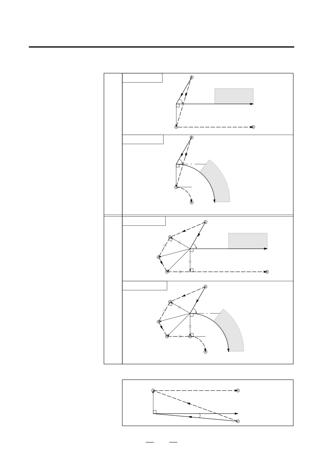
14. COMPENSATION FUNCTION
PROGRAMMING
B-63534EN/02
D Tool movement around
Tool path in start-up has two types A and B, and they are selected by
the outside of an acute
parameter SUP (No.5003#0).
angle (α<90°)
Linear→Linear
Start position
G42
Workpiece
α L
Programmed path
r
S
L
Tool center path
Type
A
Linear→Circular
Start position
G42
L
α
r
Work-
piece
S
C
Tool center path
Programmed path
Linear→Linear
Start position
L
S
G42
Workpiece
r
α
L
Programmed path
r
L
L
L
Tool center path
Type
B
Linear→Circular
Start position
L
S
G42
r
α
L
r
L
Work-
L
C
piece
Tool center path
Programmed path
D Tool movement around
the outside linear→linear
S
Tool center path
at an acute angle less
L
than 1 degree
L
(α<1°)
r
Programmed path
G41
G41
Start position
Less than 1 deg
304
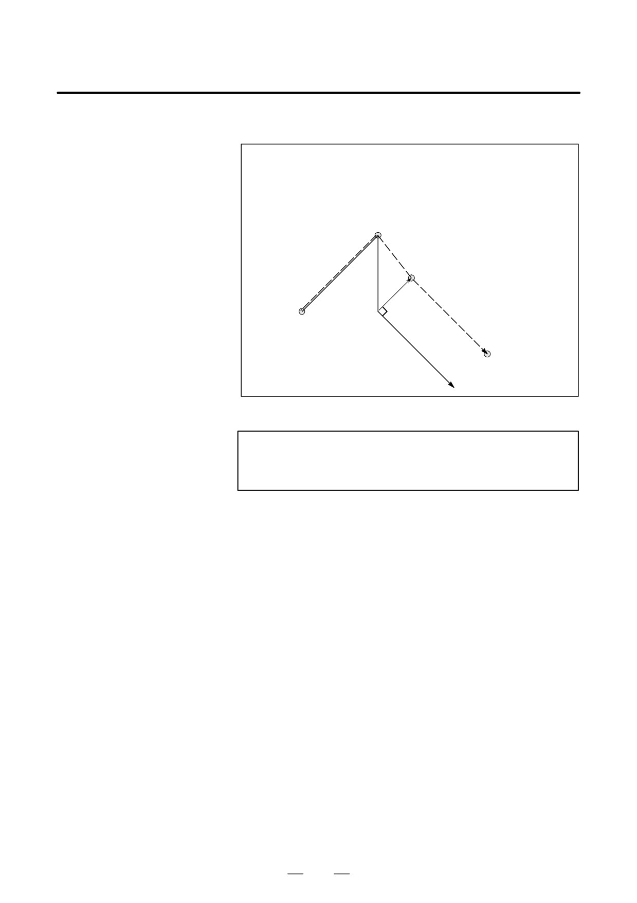
PROGRAMMING
14. COMPENSATION FUNCTION
B-63534EN/02
D A block without tool
If the command is specified at start-up, the offset vector is not created.
movement specified at
start-up
G91 G40 … ;
:
N6 X100.0 Y100.0 ;
N7 G41 X0 ;
N8 Y-100.0 ;
N9 Y-100.0 X100.0 ;
SS
N7
N6
S
N8
r
Tool center path
N9
Programmed path
NOTE
For the definition of blocks that do not move the tool, see
II-14.6.3.
305
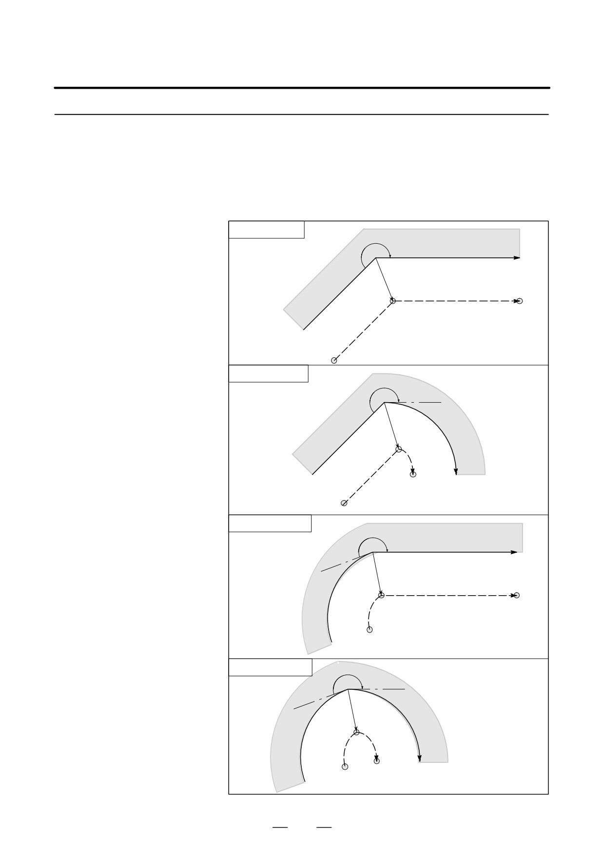
14. COMPENSATION FUNCTION
PROGRAMMING
B-63534EN/02
14.6.3
In the offset mode, the tool moves as illustrated below:
Tool Movement in
Offset Mode
Explanations
D Tool movement around
the inside of a corner
Linear→Linear
(180°xα)
α
Workpiece
Programmed path
S
L
Tool center path
Intersection
L
Linear→Circular
α
Work-
piece
Intersection
C
S
L
Programmed path
Tool center path
Circular→Linear
α
Workpiece
Programmed path
L
S
Tool center path
C
Intersection
Circular→Circular
α
Work-
Intersection
piece
S
C
C
Programmed path
Tool center path
306
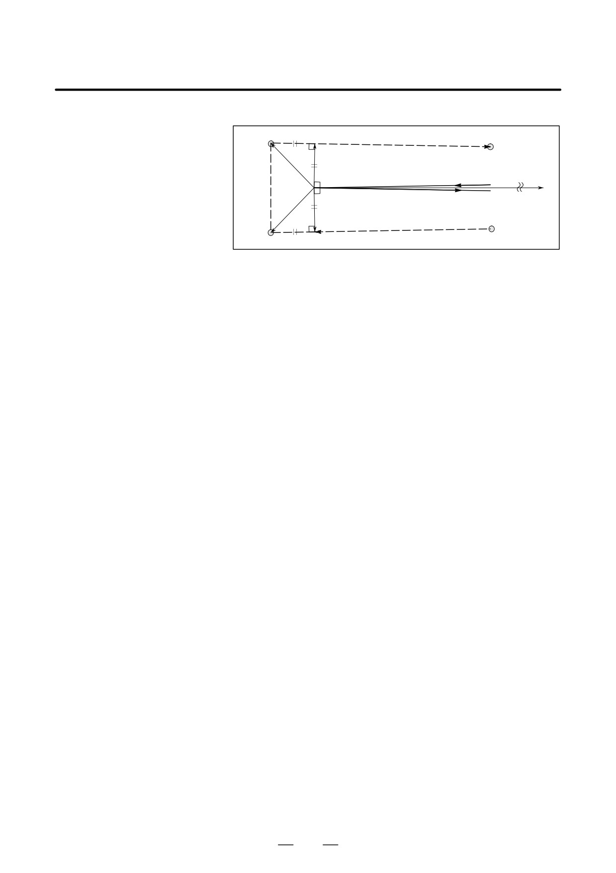
PROGRAMMING
14. COMPENSATION FUNCTION
B-63534EN/02
D Tool movement around
the inside (α<1°) with an
Intersection
abnormally long vector,
linear → linear
r
Tool center path
Programmed path
r
r
S
Intersection
Also in case of arc to straight line, straight line to arc and arc to arc, the
reader should infer in the same procedure.
307
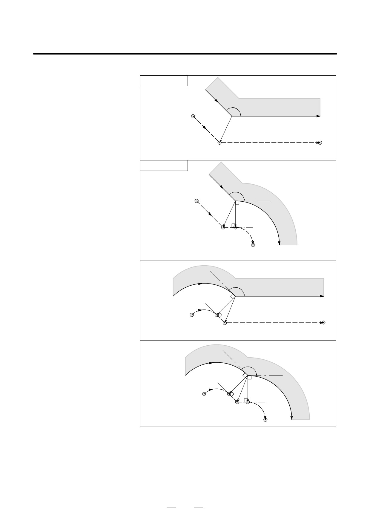
14. COMPENSATION FUNCTION
PROGRAMMING
B-63534EN/02
D Tool movement around
the outside corner at an
Linear→Linear
obtuse angle
(90°xα<180°)
α
Workpiece
L
Programmed path
S
Intersection
L
Tool center path
Linear→Circular
α
L
r
Work-
piece
L
S
C
Intersection
Programmed path
Tool center path
Circular→Linear
α
Workpiece
Programmed path
r
C
IntersectionSL
L
Tool center path
Circular→Circular
α
Programmed path
r
Work-
r
piece
C
Tool center path
S
L
L
C
Intersection
308
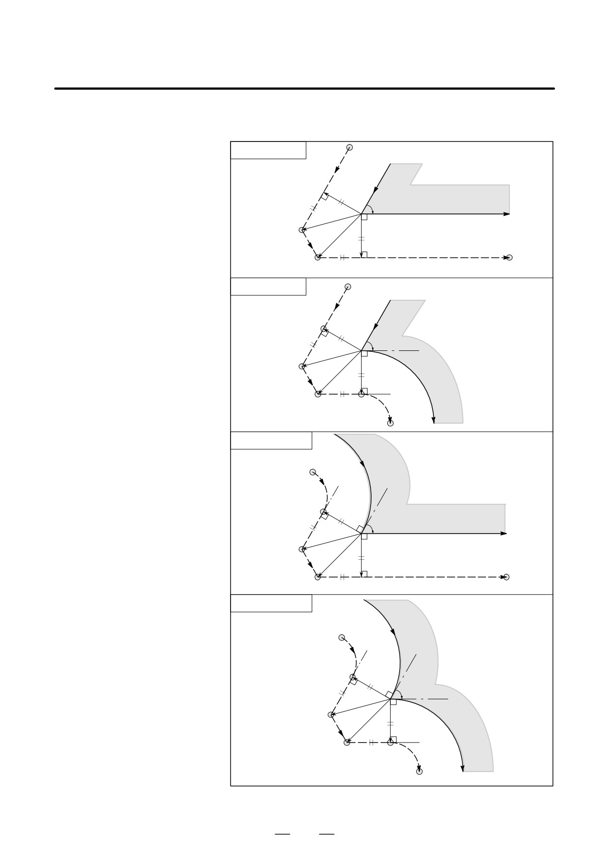
PROGRAMMING
14. COMPENSATION FUNCTION
B-63534EN/02
D Tool movement around
the outside corner at an
acute angle
Linear→Linear
(α<90°)
L
Workpiece
α
r
L
Programmed path
S
r
L
Tool center path
L
L
Linear→Circular
L
α
r
L
S
r
Work-
L
piece
L
C
Programmed path
Tool center path
Circular→Linear
C
S
Workpiece
r
α
L
Programmed path
r
L
Tool center path
L
L
Circular→Circular
C
S
α
r
L
Work-
r
piece
L
L
C
Tool center path Programmed path
309