FANUC Series 16i/160i/160is-MB, Series 18i/180i/180is-MB5, Series 18i/180i/180is-MB. Operator's Manual - page 10
13. FUNCTIONS TO SIMPLIFY
PROGRAMMING
PROGRAMMING
B-63534EN/02
D Modes that must not be
The figure cannot be copied during chamfering, corner rounding, or tool
selected
offset.
D Unit system
The two axes of the plane for copying a figure must have an identical unit
system.
D Single block
Single-block stops are not performed in a block with G721.1 or G72.2.
D Specifying cutter
In a subprogram for copying a figure, the G code for cutter compensation
compensation and the
B or C or compensation amount (H or D code) cannot be changed. G92
workpiece coordinate
and G54 to G59 cannot be changed either. Those codes must be specified
system
before figure copying is started.
Examples
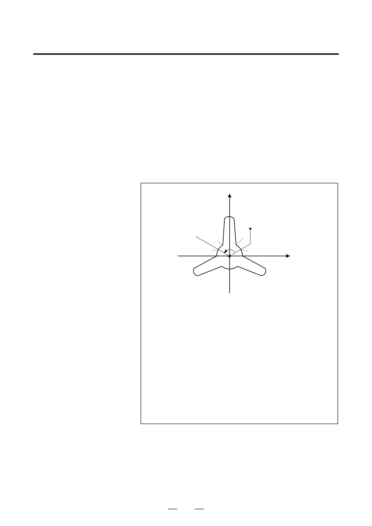
D Rotational copy
Y
P4
P3
Start point
P5
P2
P0
120
P6
P1
X
Main program
O1000 ;
N10 G92 X40.0 Y50.0 ;
N20 G00 G90 X_ Y_ ;
(P0)
N30 G01 G17 G41 X_ Y_ D01 F10 ;
(P1)
N40 G72.1 P2000 L3 X0 Y0 R120.0 ;
N50 G40 G01 X_ Y_ I_ J_ ;
(P0)
N60 G00 X40.0 Y50.0 ;
N70 M30 ;
Sub program
O2000 G03 X_ Y_ R30.0 ;
(P2)
N100 G01 X_ Y_ ;
(P3)
N200 G03 X_ Y_ R10.0 ;
(P4)
N300 G01 X_ Y_ ;
(P5)
N400 G03 X_ Y_ R30.0 ;
(P6)
N500 M99;
250
13. FUNCTIONS TO SIMPLIFY
B-63534EN/02
PROGRAMMING
PROGRAMMING
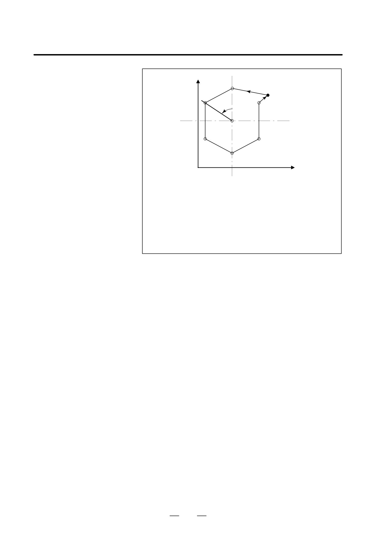
D Rotational copy
Y
(spot boring)
P1
P0
Start point
60°
X
Main program
O3000 ;
N10 G92 G17 X80.0 Y50.0 ;
(P0)
N20 G72.1 P4000 L6 X0 Y0 R60.0 ;
N30 G80 G00 X80.0 Y50.0 ;
(P0)
N40 M30 ;
Subprogram
O4000 N100 G90 G81 X_ Y_ R_ Z_ F_ ;
(P1)
N200 M99 ;
251
13. FUNCTIONS TO SIMPLIFY
PROGRAMMING
PROGRAMMING
B-63534EN/02
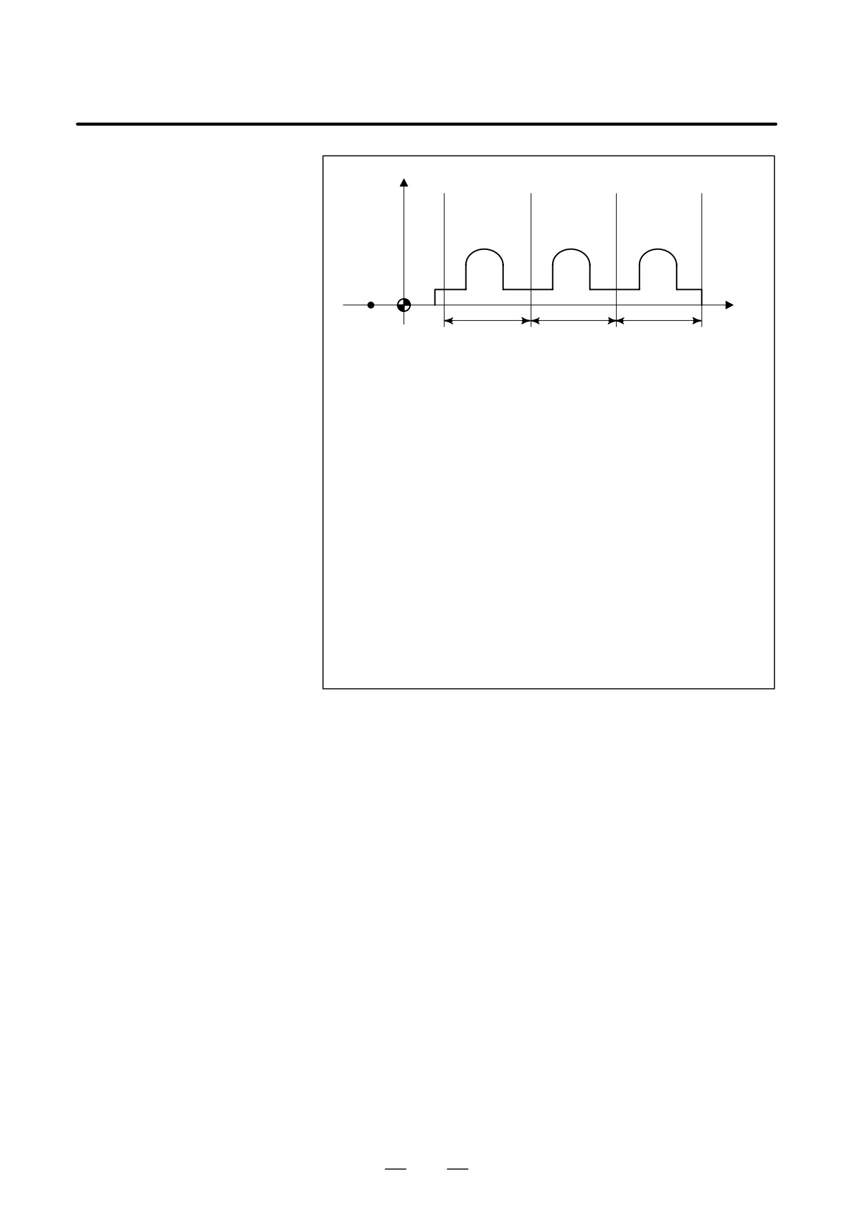
D Linear copy
Y
P4
P5
P2
P7
P
Start point
P1
P3
6
X
P0
70
70
70
P8
Main program
O1000 ;
N10 G92 X-20.0 Y0 ;
N20 G00 G90 X0 Y0 ;
N30 G01 G17 G41 X_ Y_ D01 F10 ;
(P0)
N40 Y_ ;
(P1)
N50 X_ ;
(P2)
N60 G72.2 P2000 L3 I70.0 J0 ;
N70 X_ Y_ ;
(P8)
N80 X0 ;
N90 G00 G40 X-20.0 Y0 ;
N100 M30 ;
Subprogram
O2000 G90 G01 X_ ;
(P3)
N100 Y_ ;
(P4)
N200 G02 X_ I_ ;
(P5)
N300 G01 Y_ ;
(P6)
N400 X_ ;
(P7)
N500 M99 ;
252
13. FUNCTIONS TO SIMPLIFY
B-63534EN/02
PROGRAMMING
PROGRAMMING
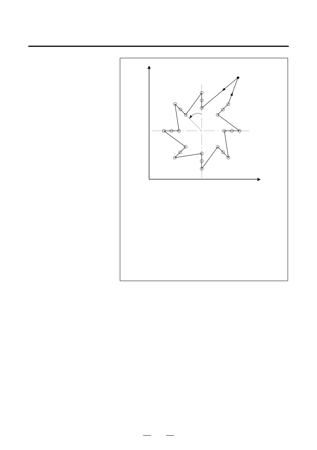
D Combination of rotational
Y
copying and linear
P0
copying (bolt hole circle)
Start point
P1
45°
X
Main program
O1000 ;
N10 G92 G17 X100.0 Y80.0 ;
(P0)
N20 G72.1 P2000 X0 Y0 L8 R45.0 ;
N30 G80 G00 X100.0 Y80.0 ;
(P0)
N40 M30 ;
Subprogram (rotational copy)
O2000 N100 G72.2 P3000 I0 J_ L3 ;
N200 M99 ;
Subprogram (linear copy)
O3000 N110 G90 G81 X_ Y_ R_ Z_ F_ ;
(P1)
N210 M99 ;
253
13. FUNCTIONS TO SIMPLIFY
PROGRAMMING
PROGRAMMING
B-63534EN/02
13.10
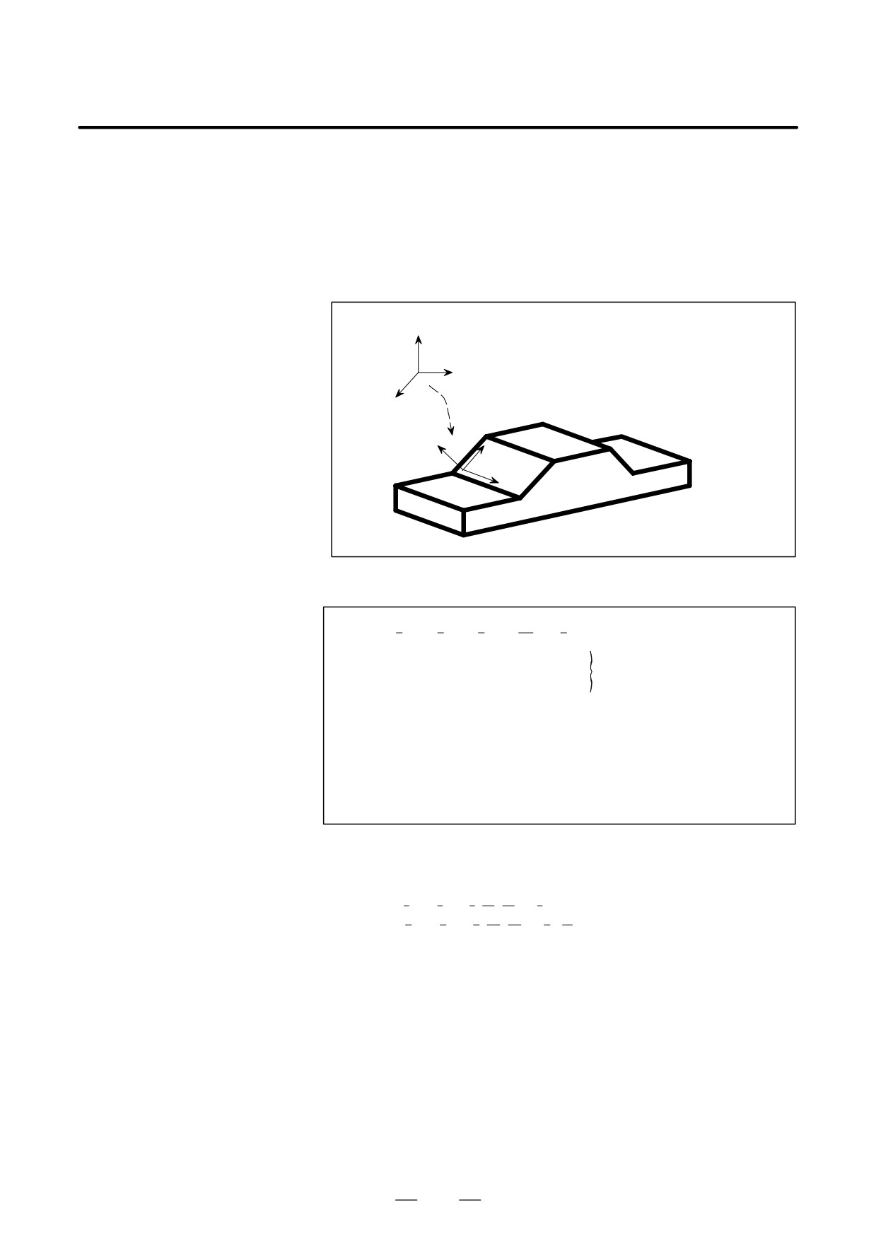
Coordinate conversion about an axis can be carried out if the center of
rotation, direction of the axis of rotation, and angular displacement are
THREE-
specified. This function is very useful in three-dimensional machining
DIMENSIONAL
by a die-sinking machine or similar machine. For example, if a program
COORDINATE
specifying machining on the XY plane is converted by the three-
dimensional coordinate conversion function, the identical machining can
CONVERSION
be executed on a desired plane in three-dimensional space.
(G68, G69)
Z
Y
X
Three-dimensional coordinate conversion
Z
Y
X
Format
G68 Xp x1 Yp y1 Zp z1 Ii1 J j1 K k1 Rα ; Starting three-dimensional
coordinate conversion
@
@
Three-dimensional coordi-
@
@
nate conversion mode
G69 ;
Canceling three-dimensional
coordinate conversion
Xp, Yp, Zp : Center of rotation (absolute coordinates) on the X, Y, and Z
axis or parallel axes
I, J, K :
Direction of the axis of rotation
R
:
Angular displacement
Explanations
D Command for
N1 G68 Xp x1 Yp y1 Zp z1 I i1 J j1 K k1 R α ;
three-dimensional
N2 G68 Xp x2 Yp y2 Zp z2 I i2 J j2 K k2 R β ;
coordinate conversion
Three-dimensional coordinate conversion can be executed twice.
(program coordinate
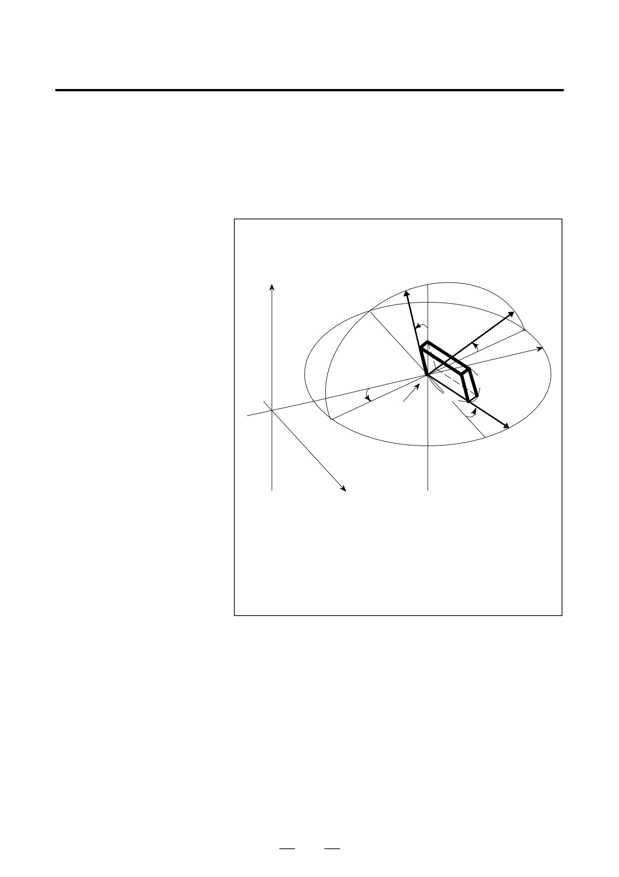
In the N1 block, specify the center, direction of the axis of rotation, and
system)
angular displacement of the first rotation. When this block is executed,
the center of the original coordinate system is shifted to (x1, y1, z1), then
rotated around the vector (i1, j1, k1) by angular displacement α. The new
coordinate system is called X’Y’Z’. In the N2 block, specify the center,
direction of the axis of rotation, and angular displacement of the second
rotation. In the N2 block, specify coordinates and the angle with the
coordinate system formed after the N1 block in Xp, Yp, Zp, I, J, K, and
R. When the N2 block is executed, the X’Y’Z’ coordinate system is
shifted to (x2, y2, z2), then rotated around the vector (i2, j2, k2) by angular
displacement β . The newest coordinate system is called X’’Y’’Z’’. In the
254
13. FUNCTIONS TO SIMPLIFY
B-63534EN/02
PROGRAMMING
PROGRAMMING
subsequent N3 block, coordinates in the X’’Y’’Z’’ coordinate system are
specified with Xp, Yp, and Zp. The X’’Y’’Z’’ coordinate system is called
the program coordinate system.
If (Xp, Yp, Zp) is not specified in the N2 block, (Xp, Yp, Zp) in the N1
block is assumed to be the center of the second rotation (the N1 and N2
blocks have a common center of rotation). If the coordinate system is to
be rotated only once, the N2 block need not be specified.
Example) G68 Xx0 Yy0 Zz0 I0 J0 K1 Rα ;
G68 I1 J0 K0 Rβ ;
Z
Z’
Z"
Y"
β
Y’
β
P (x, y, z)
z
α
x
Y
y
O (x0, y0, z0)
α
X
X, Y, Z
:
Workpiece coordinate system
X’, Y’, Z’ :
Coordinate system formed after the first conversion
X”, Y”, Z”
:
Coordinate system formed after the second conversion
α:
Angular displacement of the first rotation
β :
Angular displacement of the second rotation
O (x0, y0, z0):
Center of rotation
P (x, y, z)
: Coordinates in the X’’Y’’Z’’ coordinate system (program
coordinate system)
D Format error
If one of the following format errors is detected, P/S alarm No. 5044
occurs:
1. When I, J, or K is not specified in a block with G68
(a parameter of coordinate system rotation is not specified)
2. When I, J, and K are all set to 0 in a block with G68
3. When R is not specified in a block with G68
D Center of rotation
Specify absolute coordinates with Xp, Yp, and Zp in the G68 block.
255

13. FUNCTIONS TO SIMPLIFY
PROGRAMMING
PROGRAMMING
B-63534EN/02
D Equation for
The following equation shows the general relationship between (x, y, z)
three-dimensional
in the program coordinate system and (X, Y, Z) in the original coordinate
coordinate conversion
system (workpiece coordinate system).
X
x
x1
Y
= M1
y1
y
+
Z
z
z1
When conversion is carried out twice, the relationship is expressed as follows:
X
x
x2
x1
Y
= M1
M2
M1
y2
y1
y
+
+
Z
z
z2
z1
X, Y, Z
: Coordinates in the original coordinate system
(workpiece coordinate system)
x, y, z : Programmed value
(coordinates in the program coordinate system)
x1, y1, z1
: Center of rotation of the first conversion
x2, y2, z2
: Center of rotation of the second conversion
(coordinates in the coordinate system formed after the
first conversion)
M1
: First conversion matrix
M2
: Second conversion matrix
M1 and M2 are conversion matrices determined by an angular displacement and
rotation axis. Generally, the matrices are expressed as shown below:
n12+(1-n12) cosθ
n1n2 (1-cosθ)-n3sinθ n1n3 (1-cosθ)+n2sinθ
n1 n2 (1-cosθ)+n3 sinθ
n22+(1-n22) cosθ
n2 n3 (1-cosθ)-n1 sinθ
n1 n3 (1-cosθ)-n2 sinθ n2 n3 (1-cosθ)+n1 sinθ n32+(1-n32) cosθ
i
n1
: Cosine of the angle made by the rotation axis and X-axis
p
j
n2
: Cosine of the angle made by the rotation axis and Y-axis
p
k
n3
: Cosine of the angle made by the rotation axis and Z-axis
p
θ: Angular displacement
Value p is obtained by the following:
p = i2+j2+k2
Conversion matrices for rotation on two-dimensional planes are shown below:
(1) Coordinate conversion on the XY plane
cosθ
-sinθ
0
M= sinθ cosθ
0
0
ă0
1
(2) Coordinate conversion on the YZ plane
1
0
0
M=
0
cosθ
-sinθ
0
sinθ
cosθ
(3) Coordinate conversion on the ZX plane
cosθ
0
sinθ
M=
0
1
0
–sinθ
0
cosθ
256
13. FUNCTIONS TO SIMPLIFY
B-63534EN/02
PROGRAMMING
PROGRAMMING
D Three basic axes and
Three-dimensional coordinate conversion can be applied to a desired
their parallel axes
combination of three axes selected out of the basic three axes (X, Y, Z) and
their parallel axes. The three-dimensional coordinate system subjected
to three-dimensional coordinate conversion is determined by axis
addresses specified in the G68 block. If Xp, Yp, or Zp is not specified,
X, Y, or Z of the basic three axes is assumed. However, if the basic three
axes are not specified in parameter 1022, P/S alarm No. 048 occurs.
In a single G68 block, both a basic axis and a parallel axis cannot be
specified. If this is attempted, P/S alarm No.047 occurs.
(Example)
When U-axis, V-axis, and W-axis are parallel to the X-axis, Y-axis, and
Z-axis respectively
G68 X_ I_ J_ K_ R_ ;
XYZ coordinate system
G68 U_V_ Z_ I_ J_ K_ R_ ; UVZ coordinate system
G68 W_ I_ J_ K_ R_ ;
XYW coordinate system
D Specifying the second
Three-dimensional coordinate conversion can be executed twice. The
conversion
center of rotation of the second conversion must be specified with the axis
addresses specified for the first conversion. If the axis addresses of the
second conversion are different from the axis addresses of the first
conversion, the different axis addresses are ignored. An attempt to
execute three-dimensional coordinate conversion three or more times
causes P/S alarm No.5043.
D Angular displacement R
A positive angular displacement R indicates a clockwise rotation along
the axis of rotation. Specify angular displacement R in 0.001 degrees
within the range of -360000 to 360000.
D G codes that can be
The following G codes can be specified in the three-dimensional
specified
coordinate conversion mode:
G00
Positioning
G01
Linear interpolation
G02
Circular interpolation (clockwise)
G03
Circular interpolation (counterclockwise)
G04
Dwell
G10
Data setting
G17
Plane selection (XY)
G18
Plane selection (ZX)
G19
Plane selection (YZ)
G28
Reference position return
G29
Return from the reference position
G30
Return to the second, third, or fourth reference position
G40
Canceling cutter compensation
G41
Cutter compensation to the left
G42
Cutter compensation to the right
G43
Increasing tool length compensation
G44
Decreasing tool length compensation
G45
Increasing the tool offset
G46
Decreasing the tool offset
G47
Doubling the tool offset
G48
Halving the tool offset
G49
Canceling tool length compensation
G50.1
Canceling programmable mirror image
G51.1
Programmable mirror image
257
13. FUNCTIONS TO SIMPLIFY
PROGRAMMING
PROGRAMMING
B-63534EN/02
G53
Selecting the machine coordinate system
G65
Custom macro calling
G66
Continuous-state custom macro calling
G67
Canceling continuous-state custom macro calling
G73
Canned cycle (peck drilling cycle)
G74
Canned cycle (reverse tapping cycle)
G76
Canned cycle (fine boring cycle)
G80
Canceling a canned cycle
G81 to G89
Canned cycle
G90
Absolute mode
G91
Incremental mode
G94
Feed per minute
G95
Feed per rotation
G98
Canned cycle (return to the initial level)
G99
Canned cycle (return to the level of point R)
D Rapid traverse rate in
In the three-dimensional coordinate conversion mode, the rapid traverse
drilling of a canned cycle
rate in drilling of a canned cycle equals the maximum cutting feedrate.
D Compensation functions
If tool length compensation, cutter compensation, or tool offset is
specified with three-dimensional coordinate conversion, compensation
is performed first, followed by three-dimensional coordinate conversion.
D Relationship between
Three-dimensional and two-dimensional coordinate conversion use
three-dimensional and
identical G codes (G68 and G69). A G code specified with I, J, and K is
two-dimensional
processed as the command for three-dimensional coordinate conversion.
coordinate conversion
A G code not specified with I, J, and K is processed as the command for
(G68, G69)
two-dimensional coordinate conversion.
D Custom macro system
Coordinates on the workpiece coordinate system are assigned to system
variables
variables #5041 to #5048 (current position on each axis).
D Reset
If a reset occurs during three-dimensional coordinate conversion mode,
the mode is canceled and the continuous-state G code is changed to G69.
D Absolute position
The absolute coordinates based on the program or workpiece coordinate
display
system can be displayed in the three-dimensional coordinate conversion
mode. Specify a desired coordinate system in the DAK bit (bit 6 of
parameter 3106).
D Three-dimensional rigid
By specifying the rigid tapping command in three-dimensional
tapping
coordinate conversion mode, tapping can be executed in the direction of
the angle programmed by the three-dimensional coordinate conversion
command.
In three-dimensional coordinate conversion mode, ”Position Error Z”,
displayed on the spindle adjustment screen, is taken from the longitudinal
tapping axis after three-dimensional conversion.
Positioning in three-dimensional coordinate conversion mode must be
linear interpolation positioning (the LRP bit (bit 1 of parameter 1401) is
set to 1).
Three-dimensional rigid tapping cannot be executed for an axis under
simple synchronous control.
258
13. FUNCTIONS TO SIMPLIFY
B-63534EN/02
PROGRAMMING
PROGRAMMING
Limitations
D manual intervention
Three-dimensional coordinate conversion does not affect the degree of
manual intervention or manual handle interrupt.
D Positioning in the
Three-dimensional coordinate conversion does not affect positioning in
machine coordinate
the machine coordinate system (e.g. specified with G28, G30, or G53).
system
Specify linear rapid traverse when three-dimensional coordinate
D Specifying rapid traverse
conversion is executed. (Set the LRP bit, bit 1 of parameter No.1401, to
1.)
D Block with G68 or G69
In a block with G68 or G69, other G codes must not be specified. G68
must be specified with I, J, and K.
D Mirror image
Programmable mirror image can be specified, but external mirror image
(mirror image by the mirror image signal or setting) cannot be specified.
Three-dimensional coordinate conversion is carried out after the
programmable mirror image function is executed.
D Position display and
To display the absolute position when three-dimensional coordinate
compensation
conversion is executed, set bits 4 to 7 of parameter DRL, DRC, DAL, and
DAC No.3104 to 0.
D Three-dimensional
Canned cycles G41, G42, or G51.1 must be nested between G68 and G69.
coordinate conversion
(Example)
and other
G68 X100. Y100. Z100. I0. J0. K1. R45. ;
continuous-state
commands
G41 D01 ;
L
G40 ;
L
G69 ;
L
259
13. FUNCTIONS TO SIMPLIFY
PROGRAMMING
PROGRAMMING
B-63534EN/02
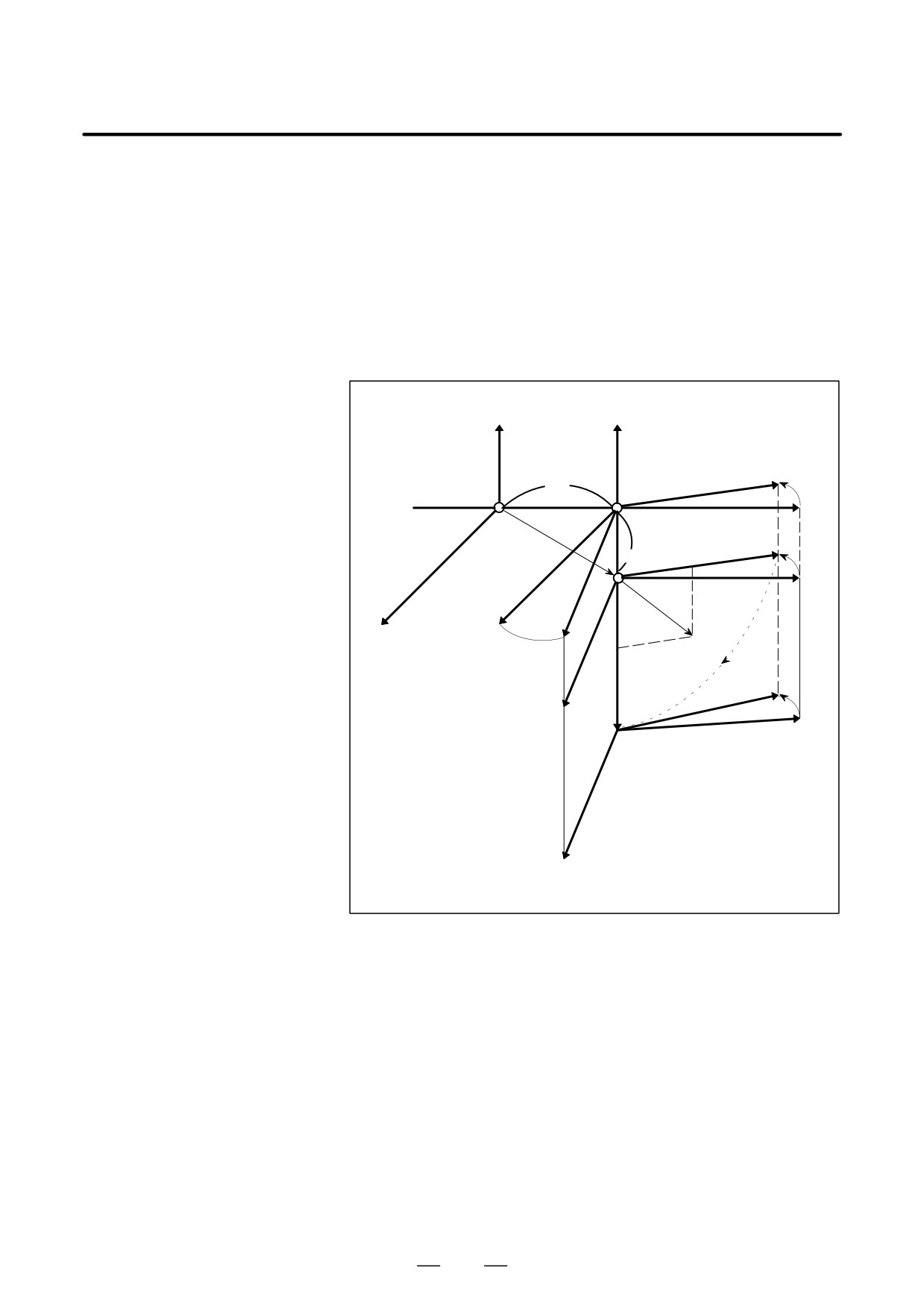
Examples
N1 G90 X0 Y0 Z0 ;
Carries out positioning to zero point H.
N2 G68 X10. Y0 Z0 I0 J1 K0 R30. ;
Forms new coordinate system X’Y’Z’.
N3 G68 X0 Y-10. Z0 I0 J0 K1 R-90. ; Forms other coordinate system X’’Y’’Z’’.
The origin agrees with
(0,
-10,
0) in
coordinate system X’Y’Z.
N4 G90 X0 Y0 Z0 ;
Carries out positioning to zero point H’’ on
coordinate system X’’Y’’Z’’.
N5 X10. Y10. Z0 ;
Carries out positioning to (10, 10, 0) on
coordinate system X’’Y’’Z’’.
Y
Y’
X’
10
30°
H
H’
X
N4
Y”
-10
H”
N5
Z
Z’
(10, 10, 0)
30°
Z”
X”
260
13. FUNCTIONS TO SIMPLIFY
B-63534EN/02
PROGRAMMING
PROGRAMMING
By specifying indexing positions (angles) for the indexing axis (one
13.11
rotation axis, A, B, or C), the index table of the machining center can be
INDEX TABLE
indexed.
INDEXING FUNCTION
Before and after indexing, the index table is automatically unclamped or
clamped .
Explanations
D Indexing position
Specify an indexing position with address A, B, or C (set to bit 0 of
parameter ROTx No.1006).
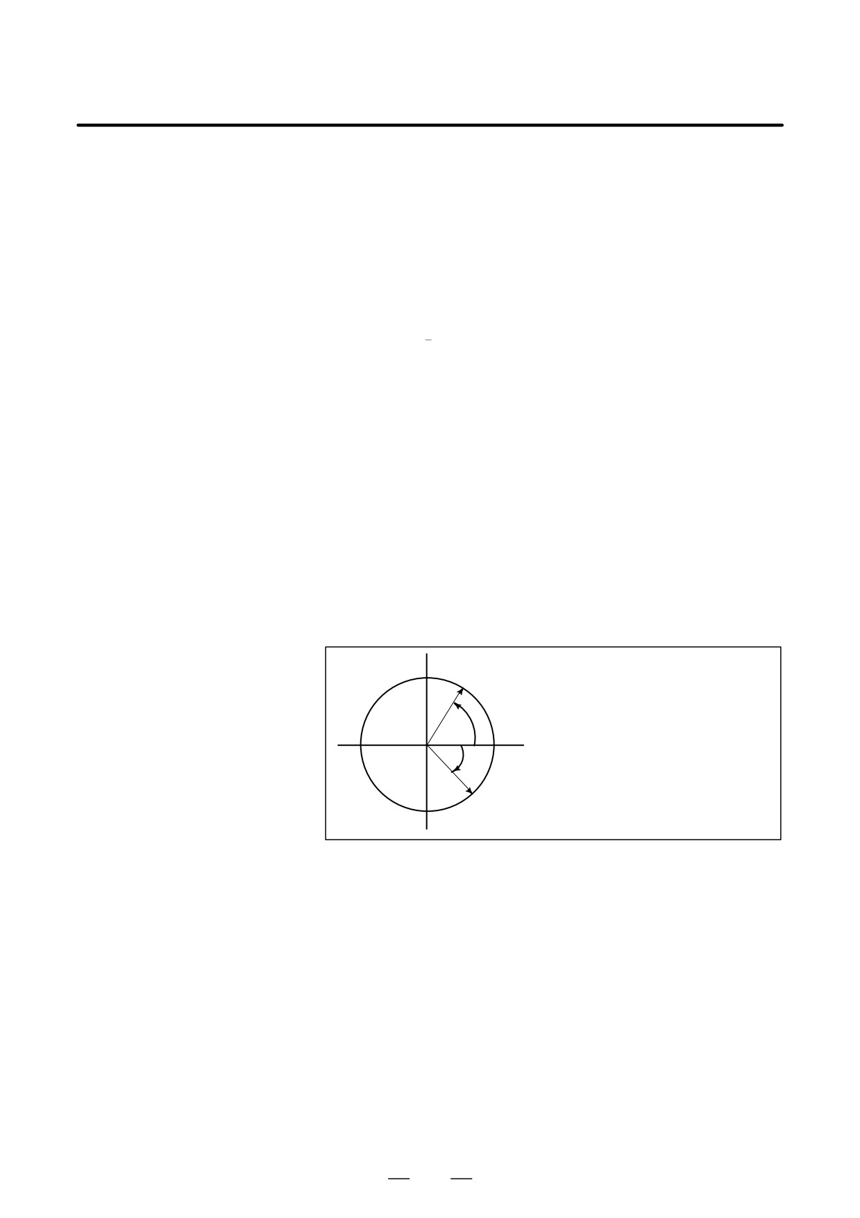
The indexing position is specified by either of the following (depending
on bit 4 of parameter G90 No.5500):
1. Absolute value only
2. Absolute or incremental value depending on the specified G code:
G90 or G91
A positive value indicates an indexing position in the counterclockwise
direction. A negative value indicates an indexing position in the
clockwise direction.
The minimum indexing angle of the index table is the value set to
parameter 5512. Only multiples of the least input increment can be
specified as the indexing angle. If any value that is not a multiple is
specified, an P/S alarm (No. 135) occurs. Decimal fractions can also be
entered. When a decimal fraction is entered, the 1’s digit corresponds to
degree units.
A
Value specified for rotation from A to B
(case 2 described above)
G90 B-45.0 ; or
G91 B-105.0;
+60°
0°
-45°
B
D Direction and value of
The direction of rotation and angular displacement are determined by
rotation
either of the following two methods. Refer to the manual written by the
machine tool builder to find out which method is applied.
1. Using the miscellaneous function specified in parameter No. 5511
(Address) (Indexing position) (Miscellaneous function);
Rotation in the negative direction
(Address) (Indexing position);
Rotation in the positive direction (No miscellaneous functions are
specified.)
An angular displacement greater than 360°is rounded down to the
corresponding angular displacement within
360°when bit
2 of
parameter ABS No. 5500 specifies this option.
For example, when G90 B400.0 (miscellaneous function); is specified
at a position of 0 , the table is rotated by 40°in the negative direction.
261

13.
FUNCTIONS TO SIMPLIFY
PROGRAMMING
PROGRAMMING
B-63534EN/02
2.
Using no miscellaneous functions
By setting to bits 2, 3, and 4 of parameter ABS, INC,G90 No.5500,
operation can be selected from the following two options.
Select the operation by referring to the manual written by the machine
tool builder.
(1) Rotating in the direction in which an angular displacement
becomes shortest
This is valid only in absolute mode. A specified angular
dis-placement greater than
360° is rounded down to the
correspond-ing angular displacement within 360° when bit 2 of
parameter ABS No.5500 specifies this option.
For example, when G90 B400.0; is specified at a position of 0, the
table is rotated by 40°in the positive direction.
(2) Rotating in the specified direction
In the absolute mode, the value set in bit 2 of parameter ABS
No.5500 determines whether an angular displacement greater than
360° is rounded down to the corresponding angular displacement
within 360°.
In the incremental mode, the angular displacement is not rounded
down.
For example, when G90 B720.0; is specified at a position of 0, the
table is rotated twice in the positive direction, when the angular
displacement is not rounded down.
D Feedrate
The table is always rotated around the indexing axis in the rapid traverse
mode.
Dry runs cannot be executed for the indexing axis.
WARNING
If a reset is made during indexing of the index table, a
reference position return must be made before each time
the index table is indexed subsequently.
NOTE
1
Specify the indexing command in a single block. If the
command is specified in a block in which another controlled
axis is specified, P/S alarm (No.136) occurs.
2
The waiting state which waits for completion of clamping or
unclamping of the index table is indicated on diagnostic
screen 12.
3
The miscellaneous function specifying a negative direction
is processed in the CNC.
The relevant M code signal and completion signal are sent
between the CNC and the machine.
4
If a reset is made while waiting for completion of clamping
or unclamping, the clamp or unclamp signal is cleared and
the CNC exits the completion wait state.
262

13. FUNCTIONS TO SIMPLIFY
B-63534EN/02
PROGRAMMING
PROGRAMMING
D Indexing function and
other functions
Table 13.11 (a) Index indexing function and other functions
Item
Explanation
This value is rounded down when bit 1 of parameter REL No. 5500
Relative position display
specifies this option.
This value is rounded down when bit 2 of parameterABS No. 5500
Absolute position display
specifies this option.
Automatic return from the reference position (G29)
2nd reference position return (G30)
Impossible to return
Movement in the machine coordinate system
Impossible to move
Single direction positioning
Impossible to specify
2nd auxiliary function (B code)
Possible with any address other than B that of the indexing axis.
Unless otherwise processed by the machine, feed hold, interlock
Operations while moving the indexing axis
and emerrgency stop can be executed. Machine lock can be
executed after indexing is completed.
Disabled
SERVO OFF signal
The indexing axis is usually in the servo-off state.
The workpiece coordinate system and machine coordinate system
Incremental commands for indexing the index
must always agree with each other on the indexing axis (the work-
table
piece zero point offset value is zero.).
Manual operation is disabled in the JOG, INC, or HANDLE mode.
A manual reference position return can be made. If the axis selec-
Operations for indexing the index table
tion signal is set to zero during manual reference position return,
movement is stopped and the clamp command is not executed.
263
14. COMPENSATION FUNCTION
PROGRAMMING
B-63534EN/02
COMPENSATION FUNCTION
14
General
This chapter describes the following compensation functions:
14.1
TOOL LENGTH OFFSET (G43, G44, G49)
14.2
AUTOMATIC TOOL LENGTH MEASUREMENT (G37)
14.3
TOOL OFFSET (G45-G48)
14.4
CUTTER COMPENSATION B (G39-G42)
14.5
CUTTER COMPENSATION C (G40-G42)
14.6
DETAILS OF CUTTER COMPENSATION C
14.7
THREE-DIMENSIONAL TOOL COMPENSATION (G40, G41)
14.8
TOOL COMPENSATION VALUES, NUMBER OF
COMPENSATION VALUES, AND ENTERING VALUES FROM
THE PROGRAM (G10)
14.9
SCALING (G50, G51)
14.10 COORDINATE SYSTEM ROTATION (G68, G69)
14.11 NORMAL DIRECTION CONTROL
(G40.1, G41.1, G42.1 OR G150, G151, G152)
14.12 PROGRAMMABLE MIRROR IMAGE (G50.1, G51.1)
14.13 GRINDING WHEEL WEAR COMPENSATION
14.14 ROTARY TABLE DYNAMIC FIXTURE OFFSET
264
PROGRAMMING
14. COMPENSATION FUNCTION
B-63534EN/02
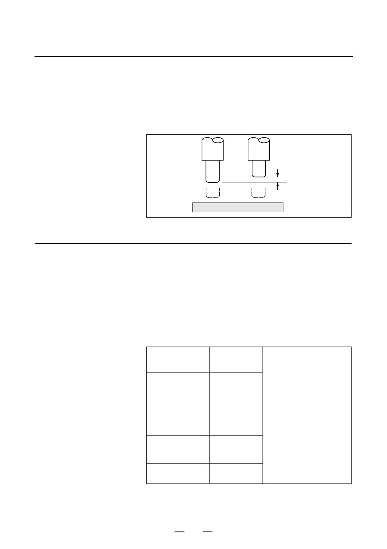
This function can be used by setting the difference between the tool length
14.1
assumed during programming and the actual tool length of the tool used
TOOL LENGTH
into the offset memory. It is possible to compensate the difference without
OFFSET
changing the program.
Specify the direction of offset with G43 or G44. Select a tool length offset
(G43, G44, G49)
value from the offset memory by entering the corresponding address and
number (H code).
Tool assumed dur-
Actual tool
ing programming
ÇÇ
ÇÇ
ÇÇ
ÇÇ
Specify this distance
ÇÇ
ÇÇ
as the value of tool
ÇÇ
length offset.
Fig. 14.1 Tool length offset
14.1.1
The following three methods of tool length offset can be used, depending
on the axis along which tool length offset can be made.
General
⋅Tool length offset A
Compensates for the difference in tool length along the Z-axis.
⋅Tool length offset B
Compensates for the difference in tool length along the X-,Y-,or
Z-axis.
⋅Tool length offset C
Compensates for the difference in tool length along a specified axis.
Format
Tool length offset A
G43 Z_ H_ ;
Explanation of each address
G44 Z_ H_ ;
G43
: Positive offset
G44
: Negative offset
Tool length offset B
G17 G43 Z_ H_ ;
G17
: XY plane selection
G17 G44 Z_ H_ ;
G18
: ZX plane selection
G18 G43 Y_ H_ ;
G19
: YZ plane selection
G18 G44 Y_ H_ ;
α : Address of a specified
G19 G43 X_ H_ ;
axis
G19 G44 X_ H_ ;
H : Address for specifying
the tool length offset
Tool length offset C
G43 α_ H_ ;
value
G44 α_ H_ ;
Tool length offset
G49 ; or H0 ;
cancel
265

14. COMPENSATION FUNCTION
PROGRAMMING
B-63534EN/02
Explanations
D Selection of tool length
Select tool length offset A, B, or C, by setting bits 0 and 1 of parameter
offset
TLC,TLB No. 5001.
D Direction of the offset
When G43 is specified, the tool length offset value (stored in offset
memory) specified with the H code is added to the coordinates of the end
position specified by a command in the program. When G44 is specified,
the same value is subtracted from the coordinates of the end position. The
resulting coordinates indicate the end position after compensation,
regardless of whether the absolute or incremental mode is selected.
If movement along an axis is not specified, the system assumes that a
move command that causes no movement is specified. When a positive
value is specified for tool length offset with G43, the tool is moved
accordingly in the positive direction. When a positive value is specified
with G44, the tool is moved accordingly in the negative direction. When
a negative value is specified, the tool is moved in the opposite direction.
G43 and G44 are modal G codes. They are valid until another G code
belonging to the same group is used.
D Specification of the tool
The tool length offset value assigned to the number (offset number)
length offset value
specified in the H code is selected from offset memory and added to or
subtracted from the moving command in the program.
(1) Tool length offset A/B
When the offset numbers for tool length offset A/B are specified or
modified, the offset number validation order varies, depending on the
condition, as described below.
D When OFH (bit 2 of
parameter No. 5001) = 0
O××××;
H01 ;
:
G43Z_ ;
(1)
:
G44Z_H02 ;
(2)
:
(1) Offset number H01 is valid.
H03 ;
(3)
(2) Offset number H02 is valid.
:
(3) Offset number H03 is valid.
D When OFH (bit 2 of
parameter No. 5001) = 1
O××××;
H01 ;
:
G43Z_ ;
(1)
:
G44Z_H02 ;
(2)
:
(1) Offset number H00 is valid.
H03 ;
(3)
(2) Offset number H02 is valid.
:
(3) Offset number H02 is valid.
266
PROGRAMMING
14. COMPENSATION FUNCTION
B-63534EN/02
(2) Cutter compensation C
When the offset numbers for cutter compensation C are specified or
modified, the offset number validation order varies, depending on the
condition, as described below.
D When OFH (bit 2 of
parameter No. 5001) = 0
O××××;
H01 ;
:
G43P_ ;
(1)
(1)Offset number H01 is valid.
:
(2)Offset number H02 is valid.
G44P_H02 ;
(2)
(3)Offset number H03 is valid only for
:
the axis to which compensation
H03 ;
(3)
was applied most recently.
:
D When OFH (bit 2 of
parameter No. 5001) = 1
O××××;
H01 ;
:
G43P_ ;
(1)
:
G44P_H02 ;
(2)
(1) Offset number H00 is valid.
:
(2) Offset number H02 is valid.
H03 ;
(3)
(3) Offset number H02 is valid.
:
(However, the H number displayed
is changed to 03.)
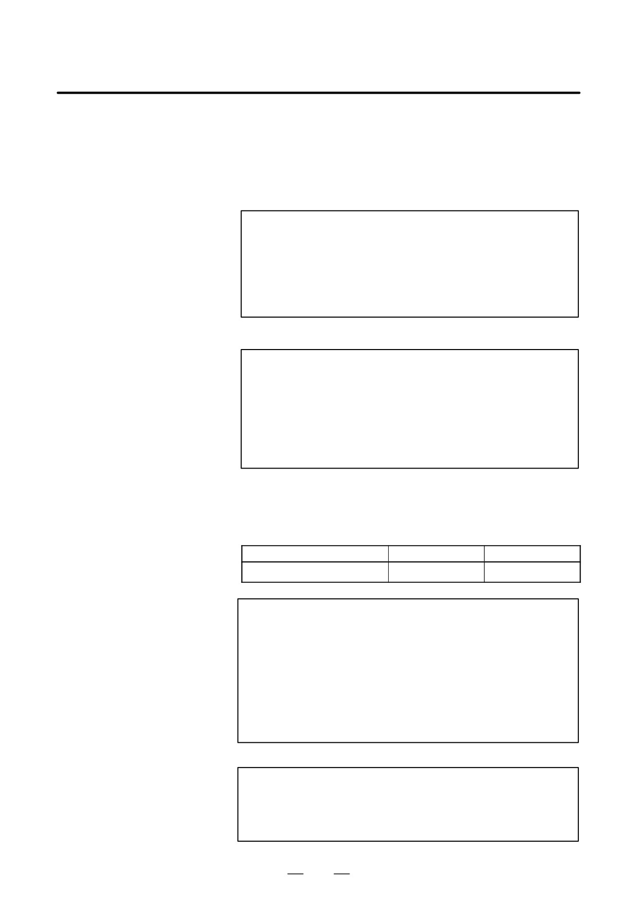
The tool length offset value may be set in the offset memory through the
CRT/MDI panel.
The range of values that can be set as the tool length offset value is as
follows.
Metric input
Inch input
Tool length offset value
0 to ±999.999mm
0 to ±99.9999inch
WARNING
When the tool length offset value is changed due to a
change of the offset number, the offset value changes to the
new tool length offset value, the new tool length offset value
is not added to the old tool length offset value.
H1 : tool length offset value 20.0
H2 : tool length offset value 30.0
G90 G43 Z100.0 H1 ; Z will move to 120.0
G90 G43 Z100.0 H2 ; Z will move to 130.0
CAUTION
When the tool length offset is used and set a parameter
OFH (No. 5001#2) to 0, specify the tool length offset with H
code and the cutter compensation with D code.
267

14. COMPENSATION FUNCTION
PROGRAMMING
B-63534EN/02
NOTE
The tool length offset value corresponding to offset No. 0,
that is, H0 always means 0. It is impossible to set any other
tool length offset value to H0.
D Performing tool length
Tool length offset B can be executed along two or more axes when the axes
offset along two or more
are specified in two or more blocks.
axes
Offset in X and Y axes.
G19 G43 H _ ; Offset in X axis
G18 G43 H _ ; Offset in Y axis
(Offsets in X and Y axes are performed)
If the TAL bit (bit 3 of parameter No. 5001) is set to 1, an alarm will not
occur even when tool length offset C is executed along two or more axes
at the same time.
D Tool length offset cancel
To cancel tool length offset, specify G49 or H0. After G49 or H0 is
specified, the system immediately cancels the offset mode.
NOTE
S After tool length offset B is executed along two or more
axes, offset along all the axes is canceled by specifying
G49. If H0 is specified, only offset along an axis
perpendicular to the specified plane is canceled.
S In the case of the offset in three axes or more, if the offset
is canceled by G49 code, the P/S alarm 015 is generated.
Cancel the offset by using G49 and H0.
268
PROGRAMMING
14. COMPENSATION FUNCTION
B-63534EN/02
Examples
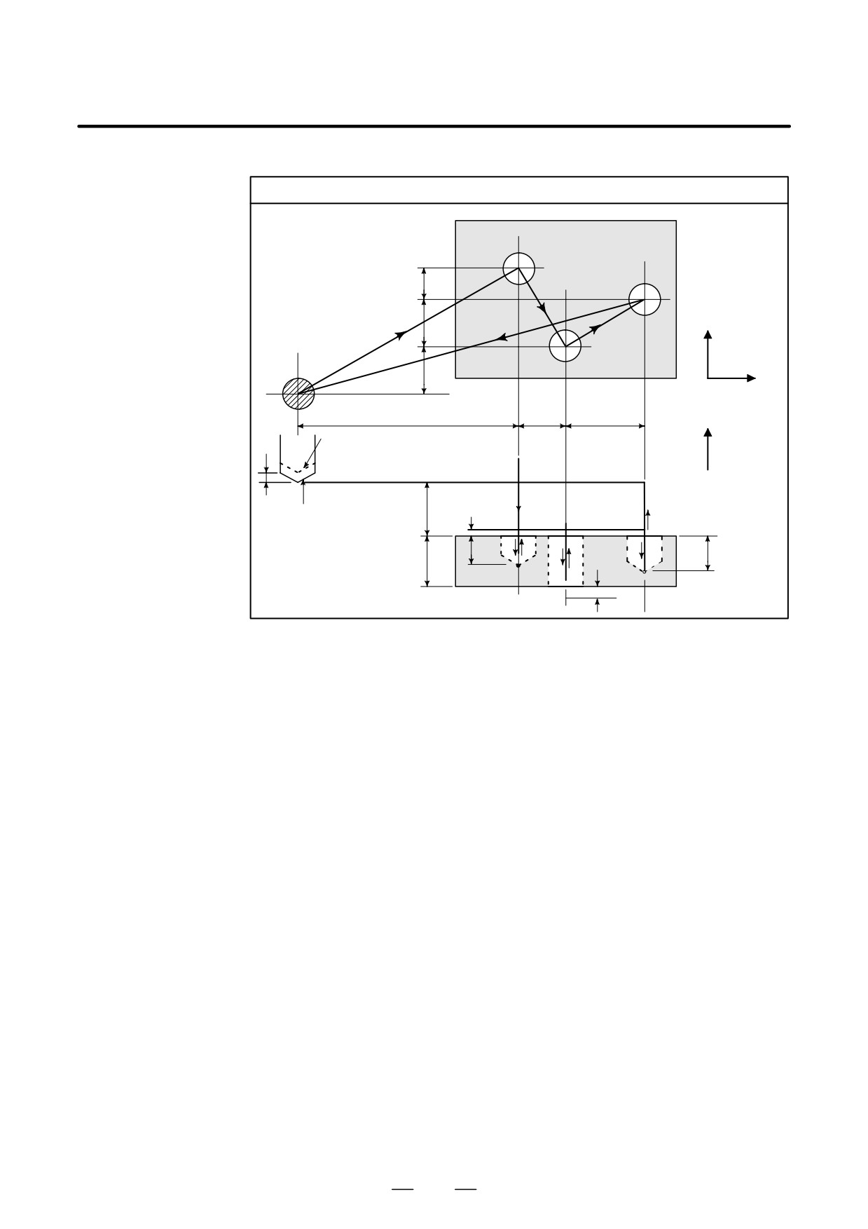
Tool length offset (in boring holes No.1, 2, and 3)
t1
t3
20
(6)
30
+Y
(9)
(13)
(1)
t2
30
+X
120
30
50
+Z
Actual position
(2)
3
Programmed
35
(12)
position
(3)
(5)
(10)
18
22
offset
(7)
(8)
30
value
(4)
(11)
ε=4mm
8
⋅Program
H1=-4.0 (Tool length offset value)
N1 G91 G00 X120.0 Y80.0 ;
(1)
N2 G43 Z-32.0 H1 ;
(2)
N3 G01 Z-21.0 F1000 ;
(3)
N4 G04 P2000 ;
(4)
N5 G00 Z21.0 ;
(5)
N6 X30.0 Y-50.0 ;
(6)
N7 G01 Z-41.0 ;
(7)
N8 G00 Z41.0 ;
(8)
N9 X50.0 Y30.0 ;
(9)
N10 G01 Z-25.0 ;
(10)
N11 G04 P2000 ;
(11)
N12 G00 Z57.0 H0 ;
(12)
N13 X-200.0 Y-60.0 ;
(13)
N14 M2 ;
269
14. COMPENSATION FUNCTION
PROGRAMMING
B-63534EN/02
14.1.2
This section describes the tool length offset cancellation and restoration
performed when G53, G28, G30, or G31 is specified in tool length offset
G53, G28, G30, and
mode. Also described is the timing of tool length offset.
G30.1 Commands in
Tool Length Offset
(1) Tool length offset vector cancellation and restoration, performed when
Mode
G53, G28, G30, or G30.1 is specified in tool length offset mode
(2) Specification of the G43/G44 command for tool length offset A/B/C,
and independent specification of the H command
Explanations
D Tool length offset vector
When G53, G28, G30, or G30.1 is specified in tool length offset mode,
cancellation
tool length offset vectors are canceled as described below. However, the
previously specified modal G code remains displayed; modal code
display is not switched to G49.
(1) When G53 is specified
Command
Specified axis
Common to type A/B/C
G53P_;
Tool length offset
Canceled upon movement being
axis
performed according to a speci-
fied value
Other than tool
Not canceled
length offset axis
NOTE
When tool length offset is applied to multiple axes, all
specified axes are subject to cancellation.
When tool length offset cancellation is specified at the same time, tool
length offset vector cancellation is performed as indicated below.
Command
Specified axis
Common to type A/B/C
Tool length offset
Canceled upon movement being
G49G53P_;
axis
performed according to a speci-
fied value
Other than tool
Canceled upon movement being
length offset axis
performed according to a speci-
fied value
(2) When G28, G30, or G30.1 is specified
Command
Specified axis
Common to type A/B/C
G28P_;
Tool length offset
Canceled upon movement to a
axis
reference position being per-
formed
Other than tool
Not canceled
length offset axis
270
PROGRAMMING
14. COMPENSATION FUNCTION
B-63534EN/02
NOTE
When tool length offset is applied to multiple axes, all
specified axes involved in reference position return are
subject to cancellation.
When tool length offset cancellation is specified at the same time, tool
length offset vector cancellation is performed as indicated below.
Command
Specified axis
Common to type A/B/C
Tool length offset
Canceled upon movement to an
G49G28P_;
axis
intermediate position being per-
formed
Other than tool
Canceled upon movement to an
length offset axis
intermediate position being per-
formed
D Tool length offset vector
Tool length offset vectors, canceled by specifying G53, G28, G30, or
restoration
G30.1 in tool length offset mode, are restored as described below.
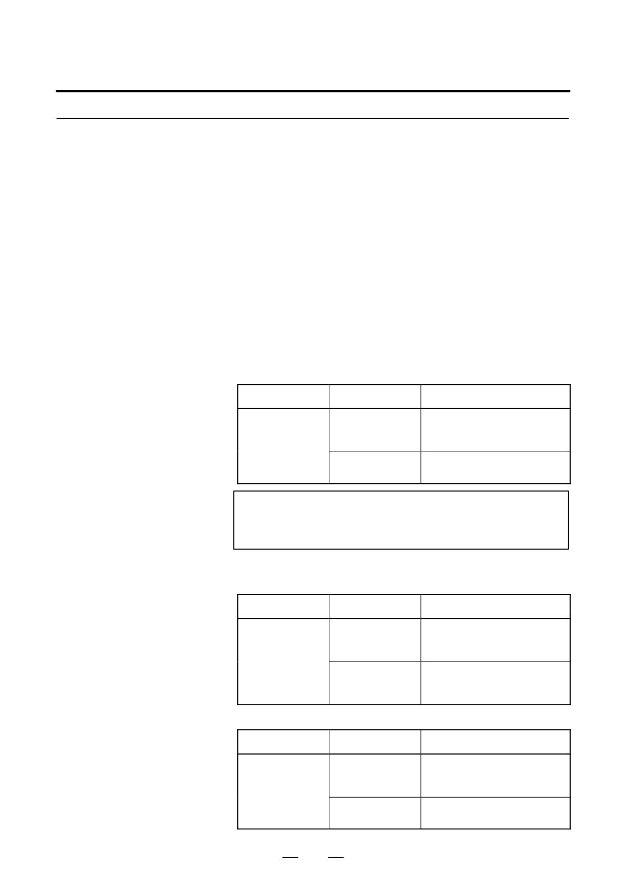
(1) When OFH (bit 2 of parameter No. 5001) = 0
Type
EVO (bit 6 of pa-
Restoration block
rameter No. 5001)
1
Block to be buffered next
A/B
0
Block containing an H command
or G43/44 command
Ignored
Block containing an H command
C
Block containing a
G43P_/G44P_ command
(2) When OFH (bit 2 of parameter No. 5001) = 1
In a mode other than tool length offset mode
Type
EVO (bit 6 of pa-
Restoration block
rameter No. 5001)
1
Block to be buffered next
A/B
0
Block containing an H command
or G43/44 command
Ignored
Block containing an H command
C
Block containing a
G43P_/G44P_ command
271
14. COMPENSATION FUNCTION
PROGRAMMING
B-63534EN/02
In tool length offset mode
Type
EVO (bit 6 of pa-
Restoration block
rameter No. 5001)
1
Block containing a G43/G44
block
A/B
0
Block containing an H command
and G43/44 command
Ignored
Block containing a
C
G43P_H_/G44P_H_ command
WARNING
When tool length offset is applied to multiple axes, all axes
for which G53, G28, G30, and G30.1 are specified are
subject to cancellation. However, restoration is performed
only for that axis to which tool length offset was applied last;
restoration is not performed for any other axes.
NOTE
In a block containing G40, G41, or G42, the tool length
offset vector is not restored.
272
PROGRAMMING
14. COMPENSATION FUNCTION
B-63534EN/02
By issuing G37 the tool starts moving to the measurement position and
14.2
keeps on moving till the approach end signal from the measurement
AUTOMATIC TOOL
device is output. Movement of the tool is stopped when the tool tip
LENGTH
reaches the measurement position.
Difference between coordinate value when tool reaches the measurement
MEASUREMENT
position and coordinate value commanded by G37 is added to the tool
(G37)
length offset amount currently used.
Z
Ç
ÇA (Start position)
Rapid
Measurement position is commanded
traverse
with G37
B (Deceleration position)
Measurement
feedrate
C (Measurement position)
The tool stops when the approach end
signal goes on.
X
0
Compensation value = (Current compensation value) + [(Coordinates of the
point at which the tool is stopped) - (Coordinates of the programmed measure-
ment position)]
Fig. 14.2 (a) Automatic tool length measurement
Format
G92
_ ; Sets the workpiece coordinate system. (It can be set
IP
with G54 to G59. See Chapter 7, “Coordinate System.”)
Hff; Specifies an offset number for tool length offset.
G90 G37IP_ ; Absolute command
G37 is valid only in the block in which it is specified.
IP
_ indicates the X-, Y-, Z-, or fourth axis.
Explanations
D Setting the workpiece
Set the workpiece coordinate system so that a measurement can be made
coordinate system
after moving the tool to the measurement position. The coordinate system
must be the same as the workpiece coordinate system for programming.
D Specifying G37
Specify the absolute coordinates of the correct measurement position.
Execution of this command moves the tool at the rapid traverse rate
toward the measurement position, reduces the federate halfway, then
continuous to move it until the approach end signal from the measuring
instrument is issued. When the tool tip reaches the measurement position,
the measuring instrument sends an approach end signal to the CNC which
stops the tool.
273
14. COMPENSATION FUNCTION
PROGRAMMING
B-63534EN/02
D Changing the offset
The difference between the coordinates of the position at which the tool
value
reaches for measurement and the coordinates specified by G37 is added
to the current tool length offset value.
Offset value =
(Current compensation value) + [(Coordinates of the position at which the
tool reaches for measurement) - (Coordinates specified by G37)]
These offset values can be manually changed from MDI.
D Alarm
When automatic tool length measurement is executed, the tool moves as
shown in Fig. 14.2 (b). If the approach end signal goes on while the tool
is traveling from point B to point C, an alarm occurs. Unless the approach
end signal goes on before the tool reaches point F, the same alarm occurs.
The P/S alarm number is 080.
Deceleration
feedrate
Rapid
(measurement
Approach end signal ON
traverse
feedrate)
A
B
C
D
E F
Start
position
Position commanded
by G37
Permitted range of approach end signal
Fig. 14.2 (b) Tool movement to the measurement position
274

PROGRAMMING
14. COMPENSATION FUNCTION
B-63534EN/02
WARNING
When a manual movement is inserted into a movement at
a measurement federate, return the tool to the!position
before the inserted manual movement for restart.
NOTE
1
When an H code is specified in the same block as G37, an
alarm is generated. Specify H code before the block!of
G37.
2
The measurement speed
(parameter No.
6241),
deceleration position (parameter No. 6251), and permitted
range of the approach end signal (parameter No. 6254) are
specified by the machine tool builder.
3
When offset memory A is used, the offset value is changed.
When offset memory B is used, the tool wear compensation
value is changed.
When offset memory C is used, the tool wear compensation
value for the H code is changed.
4
The approach end signal is monitored usually every 2 ms.
The following measuring error is generated:
ERRmax. : Fm×1/60×TS/1000 where
TS
: Sampling period, for usual 2 (ms)
ERRmax. : maximum measuring error (mm)
Fm
: measurement federate (mm/min.)
For example, when Fm = 1000 mm/min., ERRmax. = 0.003m
5
The tool stops a maximum of 16 ms after the approach end
signal is detected. But the value of the position!at which the
approach end signal was detected (note the value when the
tool stopped) is used to determine the
offset amount. The overrun for 16 ms is:
Qmax. = Fm × 1/60 ×16/1000
Qmax.: maximum overrun (mm)
Fm
:
measurement federate (mm/min.)
275
14. COMPENSATION FUNCTION
PROGRAMMING
B-63534EN/02
Examples
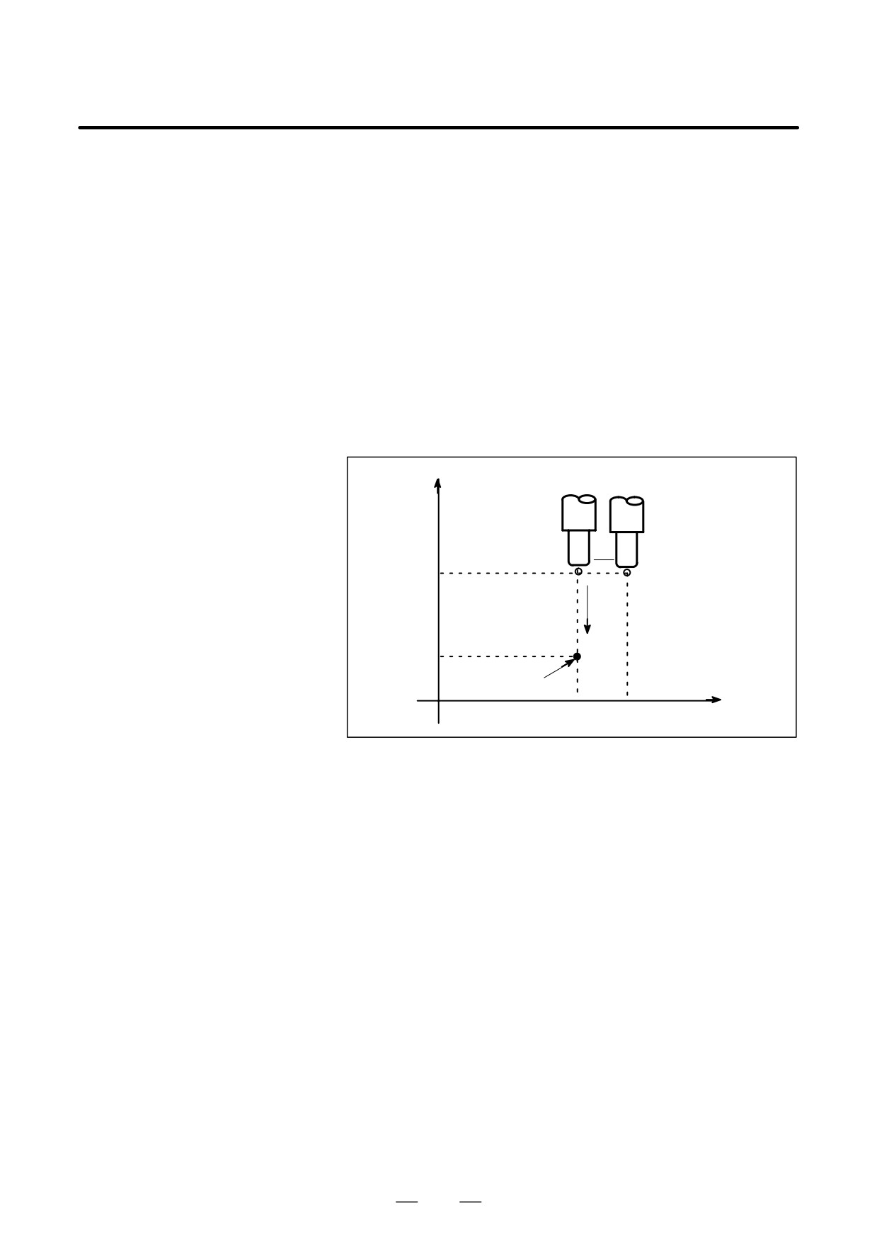
G92 Z760.0 X1100.0 ; Sets a workpiece coordinate system with
respect to the programmed absolute zero point.
G00 G90 X850.0 ;
Moves the tool to X850.0.
That is the tool is moved to a position that is a
specified distance from the measurement
position along the Z-axis.
H01 ;
Specifies offset number 1.
G37 Z200.0 ;
Moves the tool to the measurement position.
G00 Z204.0 ;
Retracts the tool a small distance along the
Z-axis.
For example, if the tool reaches the measurement position with Z198.0;,
the compensation value must be corrected. Because the correct
measurement position is at a distance of 200 mm, the compensation value
is lessened by 2.0 mm (198.0 - 200.0 = -2.0).
Z
Ç
ÇÇ
ÇÇÇÇ
760
Ç
200
Measurement
position along Z axis
0
850
1100
X
276
PROGRAMMING
14. COMPENSATION FUNCTION
B-63534EN/02
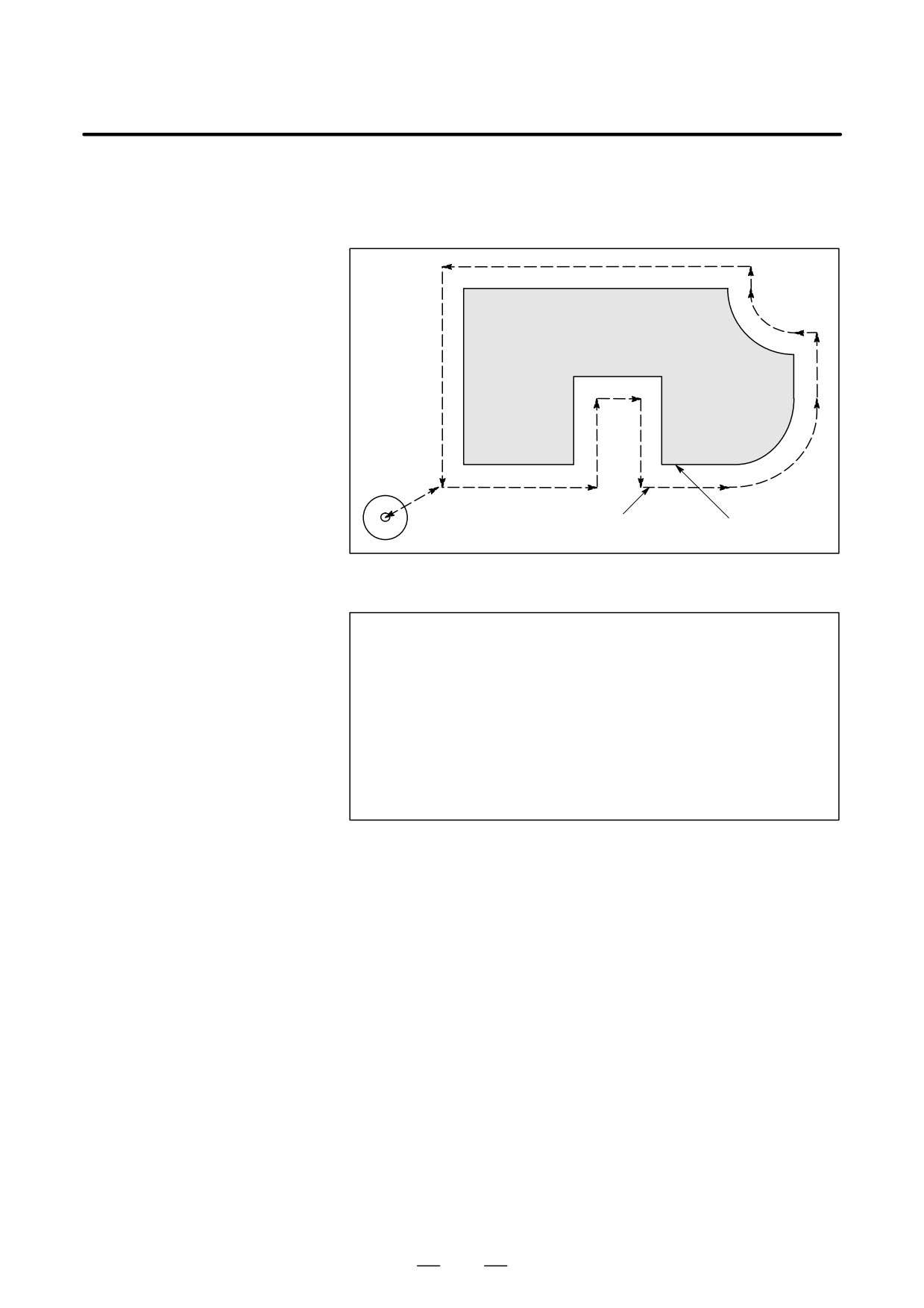
14.3
The programmed travel distance of the tool can be increased or decreased
by a specified tool offset value or by twice the offset value.
TOOL OFFSET
The tool offset function can also be applied to an additional
(G45-G48)
axis.
Workpiece
ÇÇ
ÇÇÇ
Tool center path
Programmed path
ool
ÇÇT
Format
G45
IP
_D_ ; Increase the travel distance by the tool offset value
G46IP
_D_ ; Decrease the travel distance by the tool offset value
G47
IP_D_ ;
Increase the travel distance by twice the tool offset value
G48
IP
_D_ ; Decrease the travel distance by twice the tool offset value
G45 to G48 : One-shot G code for increasing or decreasing the travel
distance
: Command for moving the tool
IP
D : Code for specifying the tool offset value
277
14. COMPENSATION FUNCTION
PROGRAMMING
B-63534EN/02
Explanations
D Increase and decrease
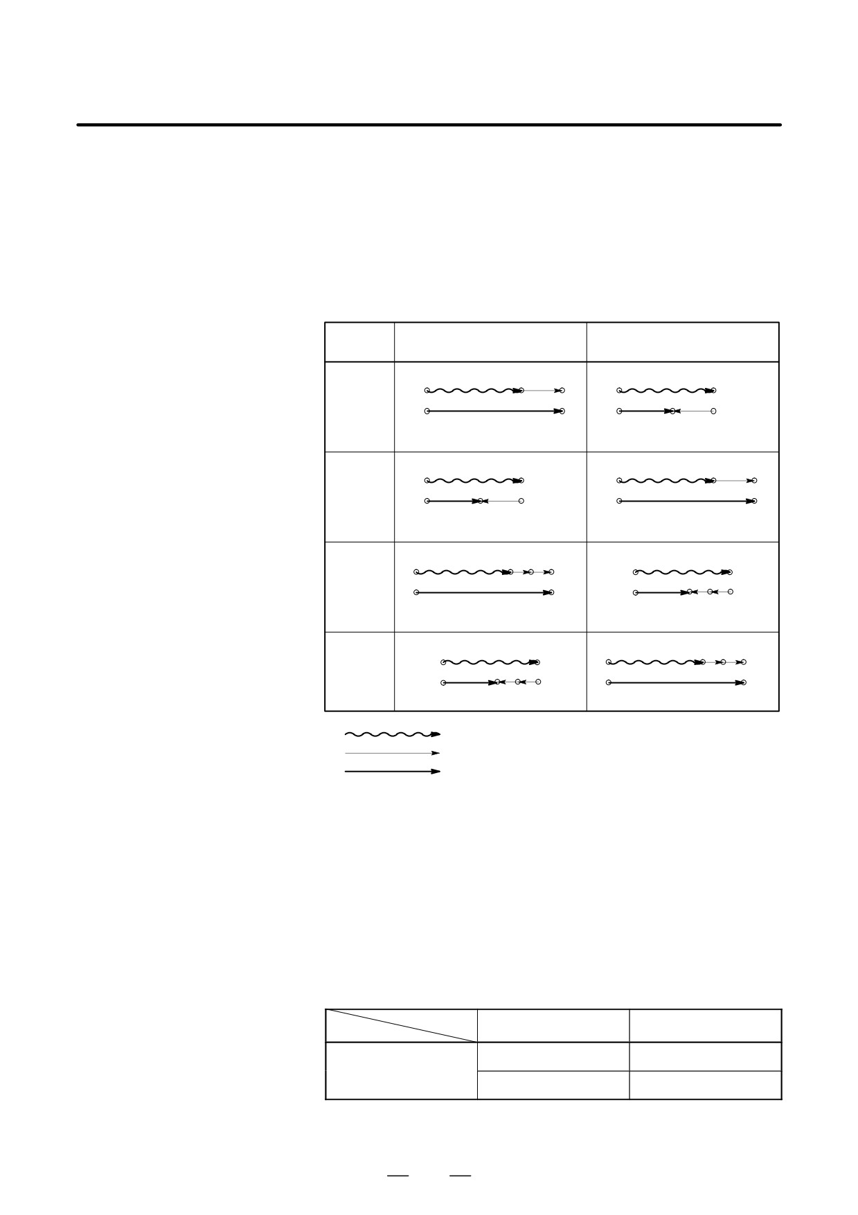
As shown in Table 14.3(a), the travel distance of the tool is increased or
decreased by the specified tool offset value.
In the absolute mode, the travel distance is increased or decreased as the
tool is moved from the end position of the previous block to the position
specified by the block containing G45 to G48.
Table 14.3 (a) Increase and decrease of the tool travel distance
When a positive tool offset val-
When a negative tool offset
G code
ue is specified
value is specified
G45
Start position
End position
Start position
End position
G46
Start position
End position
Start position
End position
G47
Start position
End position
Start position
End position
G48
Start position
End position
Start position
End position
Programmed movement distance
Tool offset value
Actual movement position
If a move command with a travel distance of zero is specified in the
incremental command (G91) mode, the tool is moved by the distance
corresponding to the specified tool offset value.
If a move command with a travel distance of zero is specified in the
absolute command (G90) mode, the tool is not moved.
D Tool offset value
Once selected by D code, the tool offset value remains unchanged until
another tool offset value is selected.
Tool offset values can be set within the following range:
Table 14.3 (b) Range of tool offset values
Metric input
inch input
Tool offset value
0 to ±999.999mm
0 to ±99.9999inch
0 to ±999.999deg
0 to ±999.999deg
D0 always indicates a tool offset value of zero.
278
PROGRAMMING
14. COMPENSATION FUNCTION
B-63534EN/02
WARNING
1
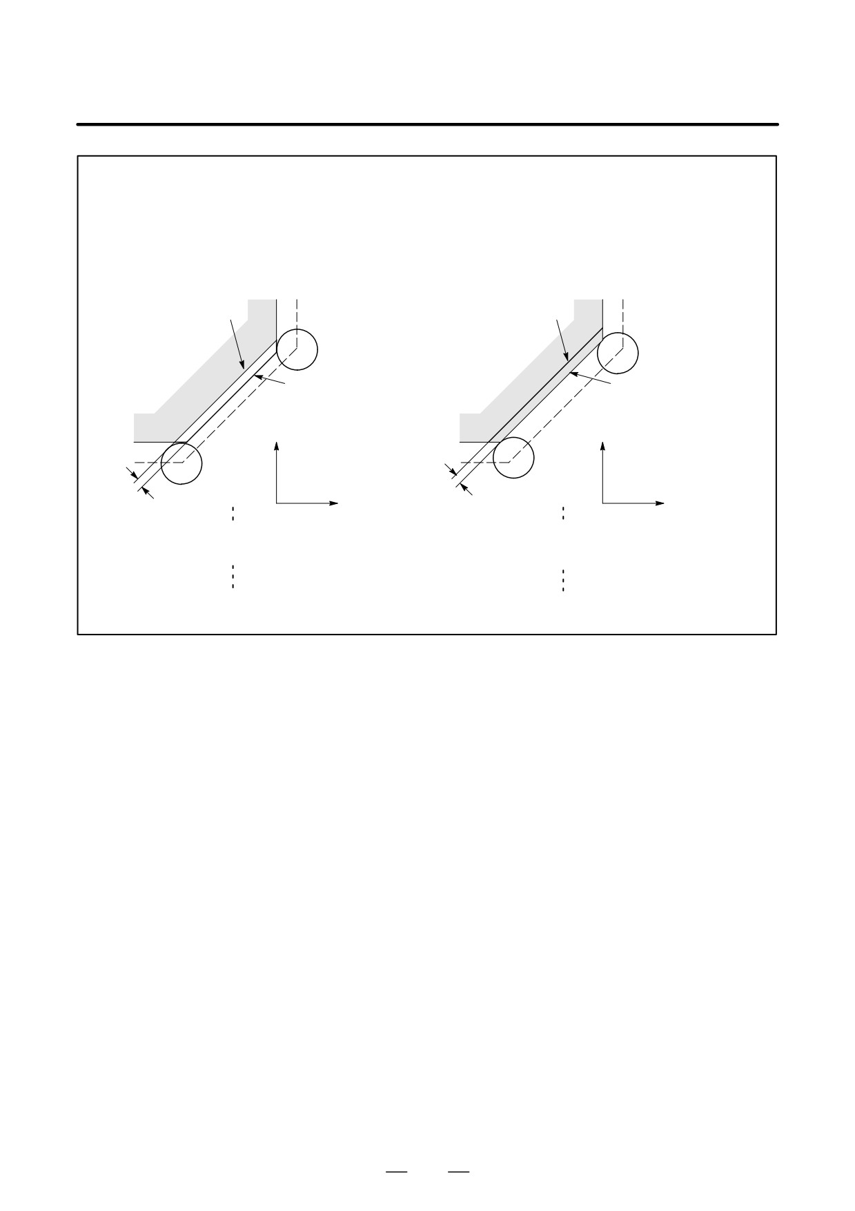
When G45 to G48 is specified to n axes (n=1-6) simultaneously in a motion block, offset is
applied to all n axes.
When the cutter is offset only for cutter radius or diameter in taper cutting, overcutting or
undercutting occurs.
Therefore, use cutter compensation (G40 or G42) shown in II-14.4 or 14.5.
Shape actually cut
Desired shape
Ç
ÇÇÇ
ÇÇ
ÇÇÇ
ÇÇ
Desired
Shape actually cut
shape
Y axis
Y axis
ÇÇ
ÇÇÇ
ÇÇÇ
ÇÇÇ
ÇÇÇ
Overcutting
Undercutting
X axis
X axis
G01 X_ F_ ;
G01 G45 X_ F_ D_;
G47 X_ Y_ D_ ;
X_ Y_ ;
Y_ ;
G45 Y_ ;
2
G45 to G48 (tool offset) must not be used in the G41 or G42 (cutter compensation) mode.
279