FANUC Series 16i/160i/160is-MB, Series 18i/180i/180is-MB5, Series 18i/180i/180is-MB. Operator's Manual - page 8
13. FUNCTIONS TO SIMPLIFY
PROGRAMMING
PROGRAMMING
B-63534EN/02
13.1.1
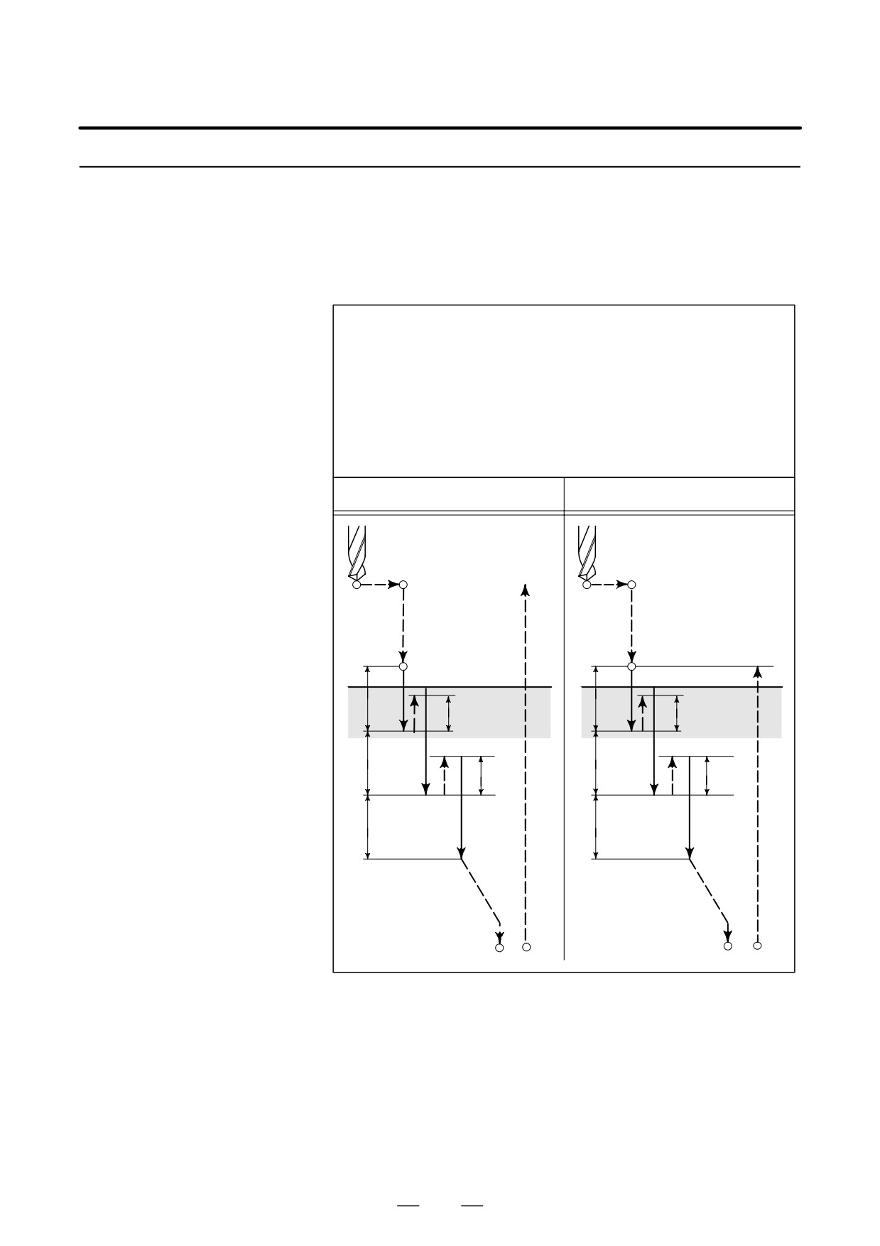
This cycle performs high-speed peck drilling. It performs intermittent
cutting feed to the bottom of a hole while removing chips from the hole.
High-Speed Peck
Drilling Cycle (G73)
Format
G73 X_ Y_ Z_ R_ Q_ F_ K_ ;
X_ Y_ : Hole position data
Z_ : The distance from point R to the bottom of the hole
R_ : The distance from the initial level to point R level
Q_ : Depth of cut for each cutting feed
F_ : Cutting feedrate
K_ : Number of repeats (if required)
G73 (G98)
G73 (G99)
Initial level
Point R
Point R
Point R level
q
q
d
d
q
q
d
d
q
q
Point Z
Point Z
190
13. FUNCTIONS TO SIMPLIFY
B-63534EN/02
PROGRAMMING
PROGRAMMING
Explanations
The high-speed peck drilling cycle performs intermittent feeding along
the Z-axis. When this cycle is used, chips can be removed from the hole
easily, and a smaller value can be set for retraction. This allows, drilling
to be performed efficiently. Set the clearance, d, in parameter 5114.
The tool is retracted in rapid traverse.
Before specifying G73, rotate the spindle using a miscellaneous function
(M code).
When the G73 code and an M code are specified in the same block, the
M code is executed at the time of the first positioning operation. The
system then proceeds to the next drilling operation.
When K is used to specify the number of repeats, the M code is executed
for the first hole only; for the second and subsequent holes, the M code
is not executed.
When a tool length offset (G43, G44, or G49) is specified in the canned
cycle, the offset is applied at the time of positioning to point R.
Limitations
D Axis switching
Before the drilling axis can be changed, the canned cycle must be
canceled.
D Drilling
In a block that does not contain X, Y, Z, R, or any other axes, drilling is
not performed.
D Q
Specify Q in blocks that perform drilling. If they are specified in a block
that does not perform drilling, they cannot be stored as modal data.
D Cancel
Do not specify a G code of the 01 group (G00 to G03 or G60 (when the
MDL bit (bit 0 of parameter 5431) is set to 1)) and G73 in a single block.
Otherwise, G73 will be canceled.
D Tool offset
In the canned cycle mode, tool offsets are ignored.
Examples
M3 S2000 ;
Cause the spindle to start rotating.
G90 G99 G73 X300. Y-250. Z-150. R-100. Q15. F120. ;
Position, drill hole 1, then return to point R.
Y-550. ;
Position, drill hole 2, then return to point R.
Y-750. ;
Position, drill hole 3, then return to point R.
X1000. ;
Position, drill hole 4, then return to point R.
Y-550. ;
Position, drill hole 5, then return to point R.
G98 Y-750. ;
Position, drill hole 6, then return to the initial
level.
G80 G28 G91 X0 Y0 Z0 ; Return to the reference position return
M5 ;
Cause the spindle to stop rotating.
191
13. FUNCTIONS TO SIMPLIFY
PROGRAMMING
PROGRAMMING
B-63534EN/02
13.1.2
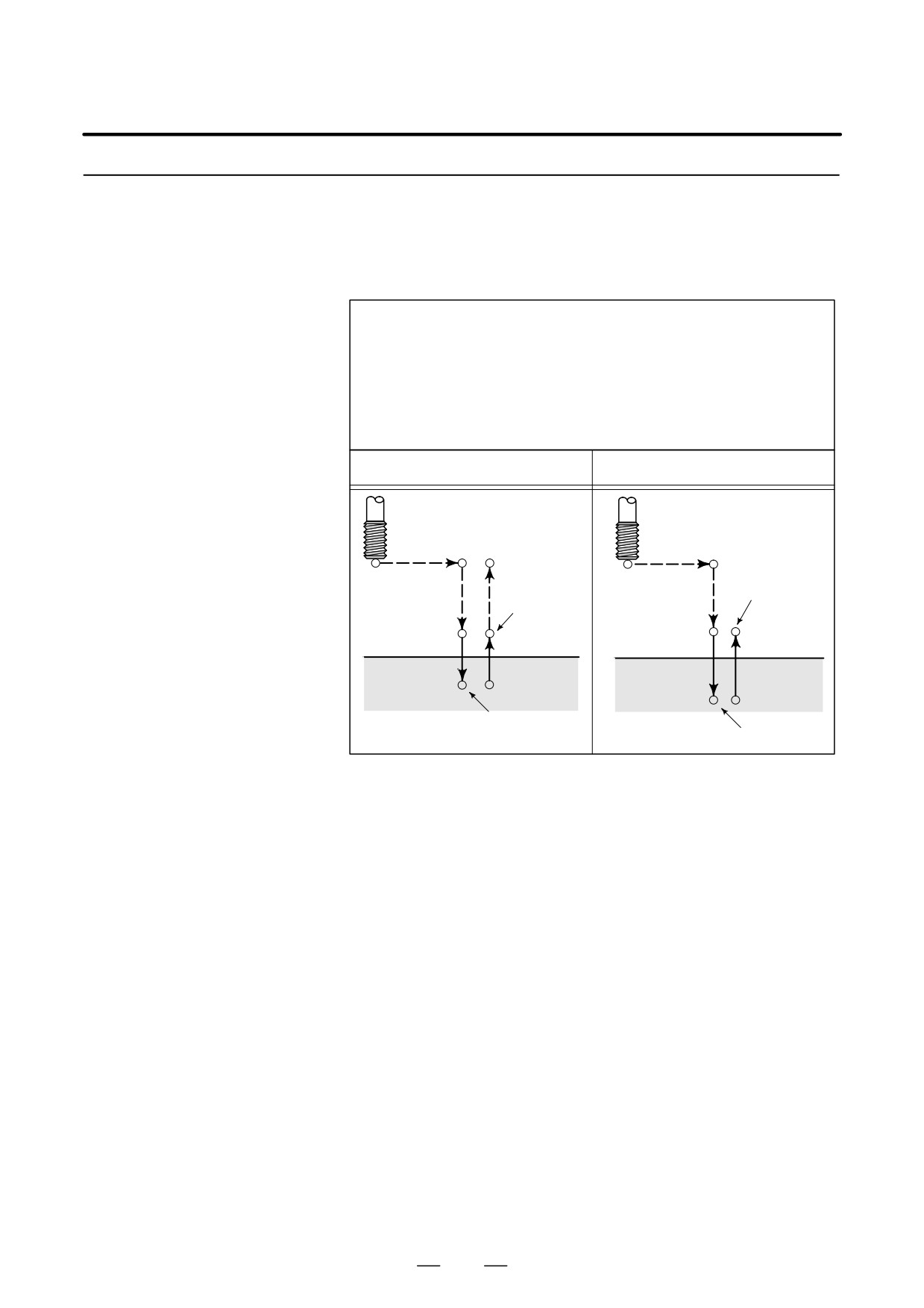
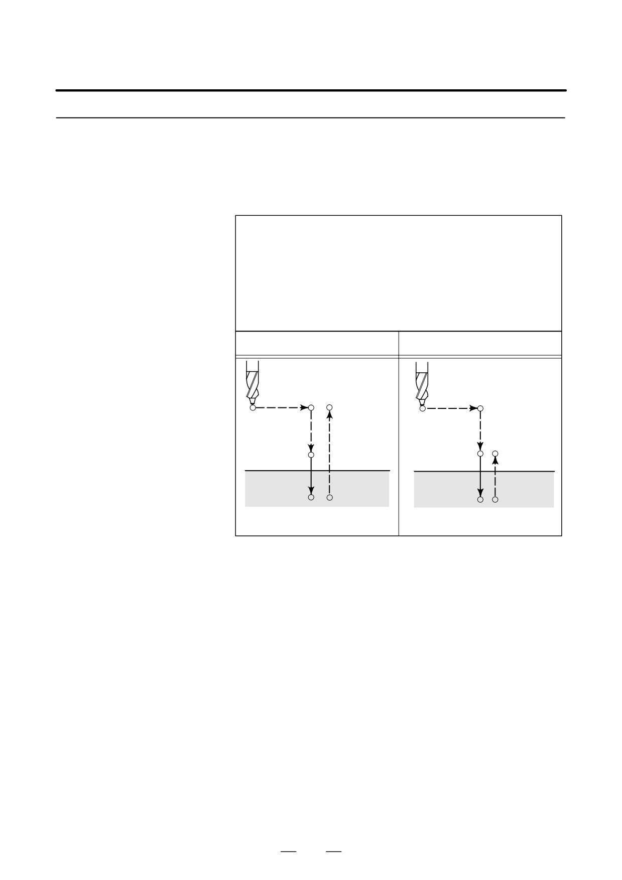
This cycle performs left-handed tapping. In the left-handed tapping
cycle, when the bottom of the hole has been reached, the spindle rotates
Left-Handed Tapping
clockwise.
Cycle (G74)
Format
G74 X_ Y_ Z_ R_P_ F_ K_ ;
X_ Y_ : Hole position data
Z_ : The distance from point R to the bottom of the hole
R_ : The distance from the initial level to point R level
P_ : Dwell time
F_ : Cutting feedrate
K_ : Number of repeats (if required)
G74 (G98)
G74 (G99)
Initial level
Spindle
CCW
Spindle
P
CCW
Point R
Point R level
Point R
P
P
Point Z
Point Z
P
Spindle CW
Spindle CW
Explanations
Tapping is performed by turning the spindle counterclockwise. When the
bottom of the hole has been reached, the spindle is rotated clockwise for
retraction. This creates a reverse thread.
Feedrate overrides are ignored during left-handed tapping. A feed hold
does not stop the machine until the return operation is completed.
Before specifying G74, use a miscellaneous function (M code) to rotate
the spindle counterclockwise.
When the G74 command and an M code are specified in the same block,
the M code is executed at the time of the first positioning operation. The
system then proceeds to the next drilling operation.
When K is used to specify the number of repeats, the M code is executed
for the first hole only; for the second and subsequent holes, the M code
is not executed.
When a tool length offset (G43, G44, or G49) is specified in the canned
cycle, the offset is applied at the time of positioning to point R.
192
13. FUNCTIONS TO SIMPLIFY
B-63534EN/02
PROGRAMMING
PROGRAMMING
Limitations
D Axis switching
Before the drilling axis can be changed, the canned cycle must be
canceled.
D Drilling
In a block that does not contain X, Y, Z, R, or any other axes, drilling is
not performed.
D P
Specify P in blocks that perform drilling. If it is specified in a block that
does not perform drilling, it cannot be stored as modal data.
D Cancel
Do not specify a G code of the 01 group (G00 to G03 or G60 (when the
MDL bit (bit 0 of parameter 5431) is set to 1)) and G74 in a single block.
Otherwise, G74 will be canceled.
D Tool offset
In the canned cycle mode, tool offsets are ignored.
D Subprogram call
In the canned cycle mode, specify the subprogram call command
M98P_in an independent block.
Examples
M4 S100 ;
Cause the spindle to start rotating.
G90 G99 G74 X300. Y-250. Z-150. R-120. F120. ;
Position, tapping hole 1, then return to point R.
Y-550. ;
Position, tapping hole 2, then return to point R.
Y-750. ;
Position, tapping hole 3, then return to point R.
X1000. ;
Position, tapping hole 4, then return to point R.
Y-550. ;
Position, tapping hole 5, then return to point R.
G98 Y-750. ;
Position, tapping hole 6, then return to the
initial level.
G80 G28 G91 X0 Y0 Z0 ; Return to the reference position return
M5 ;
Cause the spindle to stop rotating.
193
13. FUNCTIONS TO SIMPLIFY
PROGRAMMING
PROGRAMMING
B-63534EN/02
13.1.3
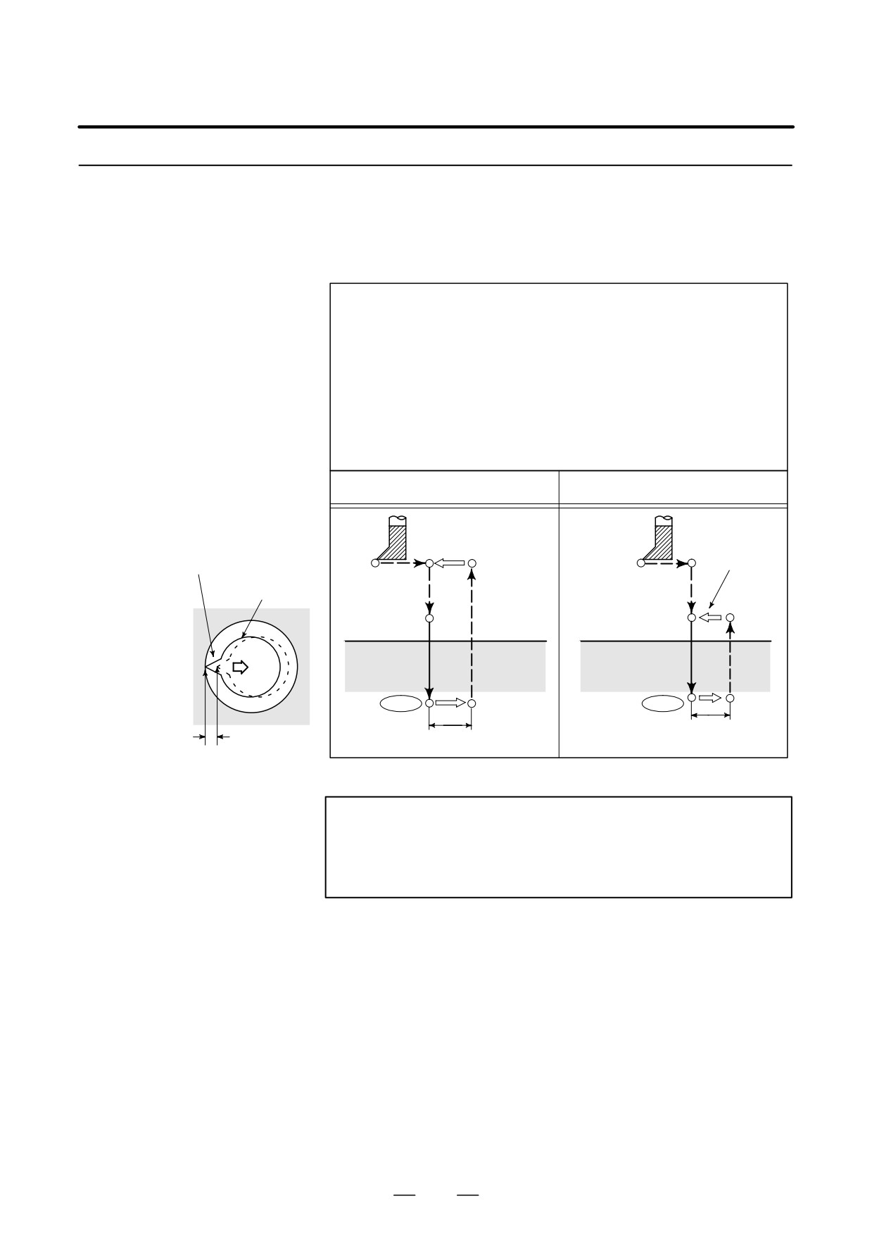
The fine boring cycle bores a hole precisely. When the bottom of the hole
has been reached, the spindle stops, and the tool is moved away from the
Fine Boring Cycle
machined surface of the workpiece and retracted.
(G76)
Format
G76 X_ Y_ Z_ R_ Q_ P_ F_ K_ ;
X_ Y_ : Hole position data
Z_ : The distance from point R to the bottom of the hole
R_ : The distance from the initial level to point R level
Q_ : Shift amount at the bottom of a hole
P_ : Dwell time at the bottom of a hole
F_ : Cutting feedrate
K_ : Number of repeats (if required)
G76 (G98)
G76 (G99)
Spindle CW
Oriented spindle stop
Initial level
Spindle CW
Tool
Point R
level
Point R
Point R
P
P
Point Z
OSS
OSS
q
Point Z
q
Shift amount q
WARNING
Q (shift at the bottom of a hole) is a modal value retained
within canned cycles. It must be specified carefully because
it is also used as the depth of cut for G73 and G83.
194
13. FUNCTIONS TO SIMPLIFY
B-63534EN/02
PROGRAMMING
PROGRAMMING
Explanations
When the bottom of the hole has been reached, the spindle is stopped at
the fixed rotation position, and the tool is moved in the direction opposite
to the tool tip and retracted. This ensures that the machined surface is not
damaged and enables precise and efficient boring to be performed.
Before specifying G76, use a miscellaneous function (M code) to rotate
the spindle.
When the G76 command and an M code are specified in the same block,
the M code is executed at the time of the first positioning operation. The
system then proceeds to the next operation.
When K is used to specify the number of repeats, the M code is executed
for the first hole only; for the second and subsequent holes, the M code
is not executed.
When a tool length offset (G43, G44, or G49) is specified in the canned
cycle, the offset is applied at the time of positioning to point R.
Limitations
D Axis switching
Before the drilling axis can be changed, the canned cycle must be
canceled.
D Boring
In a block that does not contain X, Y, Z, R, or any additional axes, boring
is not performed.
D P/Q
Be sure to specify a positive value in Q. If Q is specified with a negative
value, the sign is ignored. Set the direction of shift in bits 4 (RD1) and
5 (RD2) of parameter 5101. Specify P and Q in a block that performs
boring. If they are specified in a block that does not perform boring, they
are not stored as modal data.
D Cancel
Do not specify a G code of the 01 group (G00 to G03 or G60 (when the
MDL bit (bit 0 of parameter 5431) is set to 1)) and G76 in a single block.
Otherwise, G76 will be canceled.
D Tool offset
In the canned cycle mode, tool offsets are ignored.
D Subprogram call
In the canned cycle mode, specify the subprogram call command
M98P_in an independent block.
Examples
M3 S500 ;
Cause the spindle to start rotating.
G90 G99 G76 X300. Y-250. Position, bore hole 1, then return to point R.
Z-150. R-120. Q5.
Orient at the bottom of the hole, then shift
by 5 mm.
P1000 F120. ;
Stop at the bottom of the hole for 1 s.
Y-550. ;
Position, drill hole 2, then return to point R.
Y-750. ;
Position, drill hole 3, then return to point R.
X1000. ;
Position, drill hole 4, then return to point R.
Y-550. ;
Position, drill hole 5, then return to point R.
G98 Y-750. ;
Position, drill hole 6, then return to the initial
level.
G80 G28 G91 X0 Y0 Z0 ; Return to the reference position return
M5 ;
Cause the spindle to stop rotating.
195
13. FUNCTIONS TO SIMPLIFY
PROGRAMMING
PROGRAMMING
B-63534EN/02
13.1.4
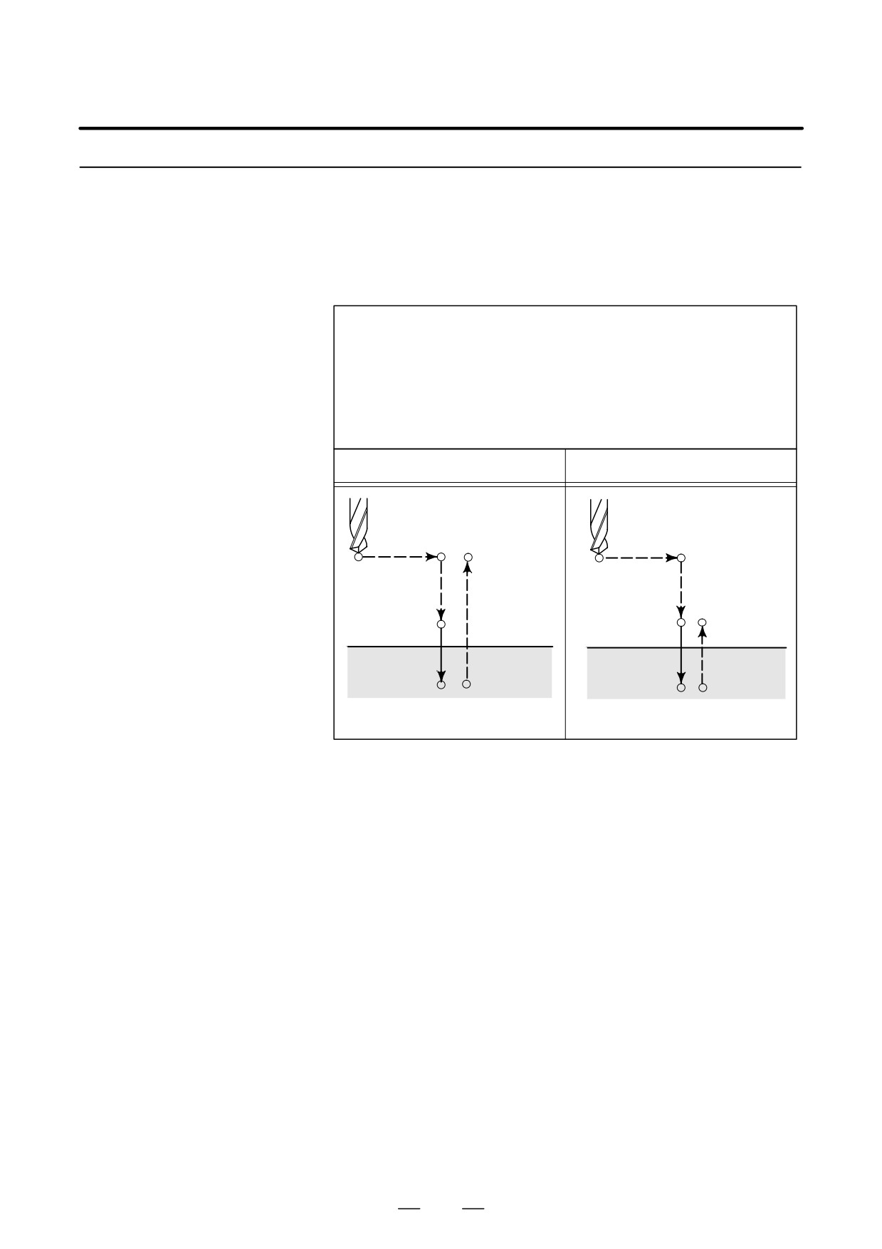
This cycle is used for normal drilling. Cutting feed is performed to the
bottom of the hole. The tool is then retracted from the bottom of the hole
Drilling Cycle, Spot
in rapid traverse.
Drilling (G81)
Format
G81 X_ Y_ Z_ R_ F_ K_ ;
X_ Y_ : Hole position data
Z_ : The distance from point R to the bottom of the hole
R_ : The distance from the initial level to point R level
F_ : Cutting feedrate
K_ : Number of repeats (if required)
G81 (G98)
G81 (G99)
Initial level
Point R level
Point R
Point R
Point Z
Point Z
Explanations
After positioning along the X- and Y-axes, rapid traverse is performed
to point R.
Drilling is performed from point R to point Z.
The tool is then retracted in rapid traverse.
Before specifying G81, use a miscellaneous function (M code) to rotate
the spindle.
When the G81 command and an M code are specified in the same block,
the M code is executed at the time of the first positioning operation. The
system then proceeds to the next drilling operation.
When K is used to specify the number of repeats, the M code is performed
for the first hole only; for the second and subsequent holes, the M code
is not executed.
When a tool length offset (G43, G44, or G49) is specified in the canned
cycle, the offset is applied at the time of positioning to point R.
196
13. FUNCTIONS TO SIMPLIFY
B-63534EN/02
PROGRAMMING
PROGRAMMING
Restrictions
D Axis switching
Before the drilling axis can be changed, the canned cycle must be
canceled.
D Drilling
In a block that does not contain X, Y, Z, R, or any other axes, drilling is
not performed.
D Cancel
Do not specify a G code of the 01 group (G00 to G03 or G60 (when the
MDL bit (bit 0 of parameter 5431) is set to 1)) and G81 in a single block.
Otherwise, G81 will be canceled.
D Tool offset
In the canned cycle mode, tool offsets are ignored.
Examples
M3 S2000 ;
Cause the spindle to start rotating.
G90 G99 G81 X300. Y-250. Z-150. R-100. F120. ;
Position, drill hole 1, then return to point R.
Y-550. ;
Position, drill hole 2, then return to point R.
Y-750. ;
Position, drill hole 3, then return to point R.
X1000. ;
Position, drill hole 4, then return to point R.
Y-550. ;
Position, drill hole 5, then return to point R.
G98 Y-750. ;
Position, drill hole 6, then return to the initial
level.
G80 G28 G91 X0 Y0 Z0 ; Return to the reference position return
M5 ;
Cause the spindle to stop rotating.
197
13. FUNCTIONS TO SIMPLIFY
PROGRAMMING
PROGRAMMING
B-63534EN/02
13.1.5
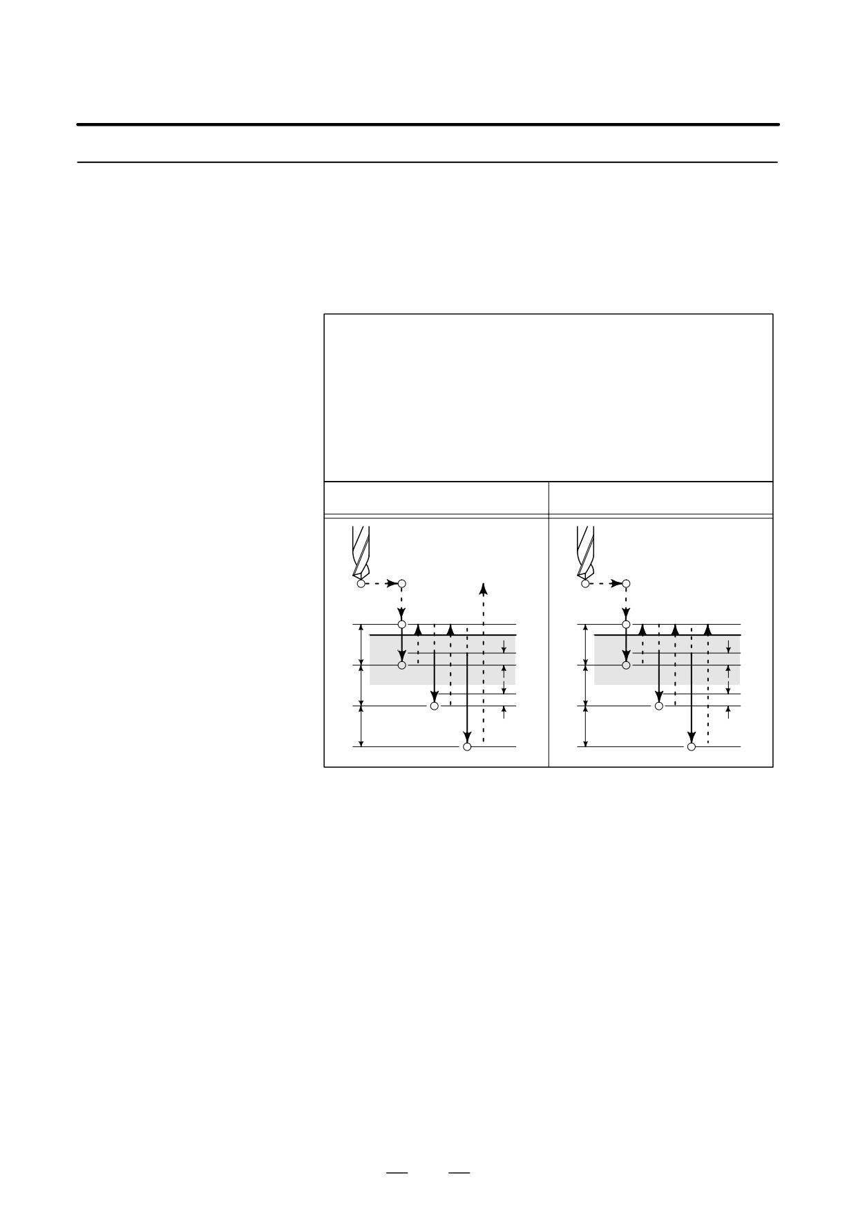
This cycle is used for normal drilling.
Cutting feed is performed to the bottom of the hole. At the bottom, a dwell
Drilling Cycle Counter
is performed, then the tool is retracted in rapid traverse.
Boring Cycle (G82)
This cycle is used to drill holes more accurately with respect to depth.
Format
G82 X_ Y_ Z_ R_ P_ F_ K_ ;
X_ Y_ : Hole position data
Z_ : The distance from point R to the bottom of the hole
R_ : The distance from the initial level to point R level
P_ : Dwell time at the bottom of a hole
F_ : Cutting feed rate
K_ : Number of repeats (if required)
G82 (G98)
G82 (G99)
Initial level
Point R level
Point R
Point R
Point Z
Point Z
P
P
Explanations
After positioning along the X- and Y-axes, rapid traverse is performed
to point R.
Drilling is then performed from point R to point Z.
When the bottom of the hole has been reached, a dwell is performed. The
tool is then retracted in rapid traverse.
Before specifying G82, use a miscellaneous function (M code) to rotate
the spindle.
When the G82 command and an M code are specified in the same block,
the M code is executed at the time of the first positioning operation. The
system then proceeds to the next drilling operation.
When K is used to specify the number of repeats, the M code is executed
for the first hole only; for the second and subsequent holes, the M code
is not executed.
When a tool length offset (G43, G44, or G49) is specified in the canned
cycle, the offset is applied at the time of positioning to point R.
198
13. FUNCTIONS TO SIMPLIFY
B-63534EN/02
PROGRAMMING
PROGRAMMING
Restrictions
D Axis switching
Before the drilling axis can be changed, the canned cycle must be
canceled.
D Drilling
In a block that does not contain X, Y, Z, R, or any other axes, drilling is
not performed.
D P
Specify P in blocks that perform drilling. If it is specified in a block that
does not perform drilling, it cannot be stored as modal data.
D Cancel
Do not specify a G code of the 01 group (G00 to G03 or G60 (when the
MDL bit (bit 0 of parameter 5431) is set to 1)) and G81 in a single block.
Otherwise, G81 will be canceled.
D Tool offset
In the canned cycle mode, tool offsets are ignored.
D Subprogram call
In the canned cycle mode, specify the subprogram call command
M98P_in an independent block.
Examples
M3 S2000 ;
Cause the spindle to start rotating.
G90 G99 G82 X300. Y-250. Z-150. R-100. P1000 F120. ;
Position, drill hole 2, and dwell for 1 s at the
bottom of the hole, then return to point R.
Y-550. ;
Position, drill hole 2, then return to point R.
Y-750. ;
Position, drill hole 3, then return to point R.
X1000. ;
Position, drill hole 4, then return to point R.
Y-550. ;
Position, drill hole 5, then return to point R.
G98 Y-750. ;
Position, drill hole 6, then return to the initial
level.
G80 G28 G91 X0 Y0 Z0 ; Return to the reference position return
M5 ;
Cause the spindle to stop rotating.
199
13. FUNCTIONS TO SIMPLIFY
PROGRAMMING
PROGRAMMING
B-63534EN/02
13.1.6
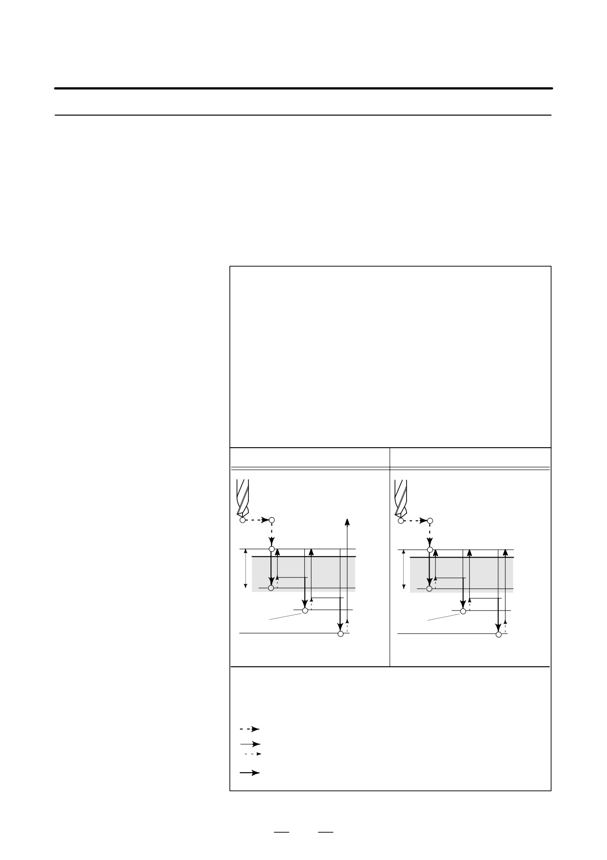
This cycle performs peck drilling.
It performs intermittent cutting feed to the bottom of a hole while
Peck Drilling Cycle
removing shavings from the hole.
(G83)
Format
G83 X_ Y_ Z_ R_ Q_ F_ K_ ;
X_ Y_ : Hole position data
Z_ : The distance from point R to the bottom of the hole
R_ : The distance from the initial level to point R level
Q_ : Depth of cut for each cutting feed
F_ : Cutting feedrate
K_ : Number of repeats (if required)
G83 (G98)
G83 (G99)
Initial level
Point R
Point R level
Point R
q
d
q
d
q
d
q
d
q
q
Point Z
Point Z
Explanations
Q represents the depth of cut for each cutting feed. It must always be
specified as an incremental value.
In the second and subsequent cutting feeds, rapid traverse is performed
up to a d point just before where the last drilling ended, and cutting feed
is performed again. d is set in parameter (No.5115).
Be sure to specify a positive value in Q. Negative values are ignored.
Before specifying G83, use a miscellaneous function (M code) to rotate
the spindle.
When the G83 command and an M code are specified in the same block,
the M code is executed at the time of the first positioning operation. The
system then proceeds to the next drilling operation.
When K is used to specify the number of repeats, the M code is executed
for the first hole only; for the second and subsequent holes, the M code
is not executed.
When a tool length offset (G43, G44, or G49) is specified in the canned
cycle, the offset is applied at the time of positioning to point R.
200
13. FUNCTIONS TO SIMPLIFY
B-63534EN/02
PROGRAMMING
PROGRAMMING
Limitations
D Axis switching
Before the drilling axis can be changed, the canned cycle must be
canceled.
D Drilling
In a block that does not contain X, Y, Z, R, or any other axes, drilling is
not performed.
D Q
Specify Q in blocks that perform drilling. If they are specified in a block
that does not perform drilling, they cannot be stored as modal data.
D Cancel
Do not specify a G code of the 01 group (G00 to G03 or G60 (when the
MDL bit (bit 0 of parameter 5431) is set to 1)) and G82 in a single block.
Otherwise, G82 will be canceled.
D Tool offset
In the canned cycle mode, tool offsets are ignored.
Examples
M3 S2000 ;
Cause the spindle to start rotating.
G90 G99 G83 X300. Y-250. Z-150. R-100. Q15. F120. ;
Position, drill hole 1, then return to point R.
Y-550. ;
Position, drill hole 2, then return to point R.
Y-750. ;
Position, drill hole 3, then return to point R.
X1000. ;
Position, drill hole 4, then return to point R.
Y-550. ;
Position, drill hole 5, then return to point R.
G98 Y-750. ;
Position, drill hole 6, then return to the initial
level.
G80 G28 G91 X0 Y0 Z0 ; Return to the reference position return
M5 ;
Cause the spindle to stop rotating.
201
13. FUNCTIONS TO SIMPLIFY
PROGRAMMING
PROGRAMMING
B-63534EN/02
13.1.7
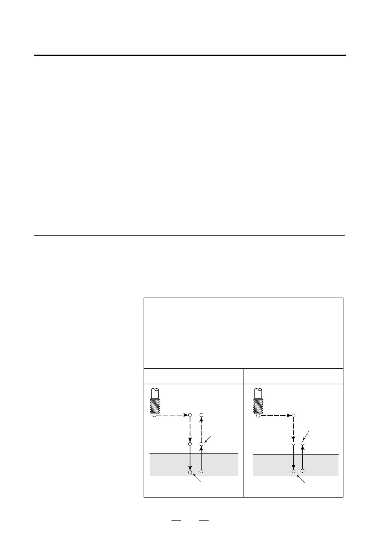
An arbor with the overload torque detection function is used to retract the
tool when the overload torque detection signal (skip signal) is detected
Small-Hole Peck
during drilling. Drilling is resumed after the spindle speed and cutting
Drilling Cycle (G83)
feedrate are changed. These steps are repeated in this peck drilling cycle.
The mode for the small-hole peck drilling cycle is selected when the M
code in parameter 5163 is specified. The cycle can be started by
specifying G83 in this mode. This mode is canceled when G80 is
specified or when a reset occurs.
Format
G83 X_ Y_ Z_ R_ Q_ F_ I_ K_ P_ ;
X_ Y_ : Hole position data
Z_ : Distance from point R to the bottom of the hole
R_ : Distance from the initial level to point R
Q_ : Depth of each cut
F_ : Cutting feedrate
I_ : Forward or backward traveling speed (same format as F above)
(If this is omitted, the values in parameters No.5172 and No.5173 are
assumed as defaults.)
K_ : Number of times the operation is repeated (if required)
P_ : Dwell time at the bottom of the hole
(If this is omitted, P0 is assumed as the default.)
G83(G98)
G83(G99)
Initial level
Point R
Point R
Q
Q
∆
∆
∆
∆
Overload torque
Overload torque
∆
∆
Point Z
Point Z
Dwell
Dwell
∆ : Initial clearance when the tool is retracted to point R and the clearance
from the bottom of the hole in the second or subsequent drilling
(parameter 5174)
Q : Depth of each cut
Path along which the tool travels at the rapid traverse rate
Path along which the tool travels (forward or backward) at the rapid
(
) traverse rate during the cycle specified with parameters
Path along which the tool travels at the programmed cutting feedrate
202
13. FUNCTIONS TO SIMPLIFY
B-63534EN/02
PROGRAMMING
PROGRAMMING
Explanations
D Component operations
of the cycle
*Positioning along the X-axis and Y-axis
*Positioning at point R along the Z-axis
*Drilling along the Z-axis (first drilling, depth of cut Q, incremental)
Retraction (bottom of the hole → small clearance ∆, incremental)
Retraction (bottom of the hole → point R)
Advance (point R → point at a height of clearance ∆ from the bottom of
the hole)
Drilling (second or subsequent drilling, depth of cut Q + ∆ , incremental)
*Dwell
*Return to point R (or initial level) along the Z-axis, cycle end
Acceleration/deceleration during advancing and retraction is controlled
according to the cutting feed acceleration/deceleration time constant.
When retraction is performed, the position is checked at point R.
D Specifying an M code
When the M code in parameter 5163 is specified, the system enters the
mode for the small-hole peck drilling cycle.
This M code does not wait for FIN. Care must be taken when this M code
is specified with another M code in the same block.
(Example) Mjj M03 ; → Waits for FIN.
M03 Mjj ; → Does not wait for FIN.
D Specifying a G code
When G83 is specified in the mode for the small-hole peck drilling cycle,
the cycle is started.
This continuous-state G code remains unchanged until another canned
cycle is specified or until the G code for cancelling the canned cycle is
specified. This eliminates the need for specifying drilling data in each
block when identical drilling is repeated.
D Signal indicating that the
In this cycle, the signal indicating that the small-hole peck drilling cycle
cycle is in progress
is in progress is output after the tool is positioned at the hole position
along the axes not used for drilling. Signal output continues during
positioning to point R along the drilling axis and terminates upon a return
to point R or the initial level. For details, refer to the manual of the
machine tool builder.
D Overload torque
A skip signal is used as the overload torque detection signal. The skip
detection signal
signal is effective while the tool is advancing or drilling and the tool tip
is between points R and Z. (The signal causes a retraction). For details,
refer to the manual of the machine tool builder.
203
13. FUNCTIONS TO SIMPLIFY
PROGRAMMING
PROGRAMMING
B-63534EN/02
D Changing the drilling
In a single G83 cycle, drilling conditions are changed for each drilling
conditions
operation (advance → drilling → retraction). Bits 1 and 2 of parameter
OLS, NOL No. 5160 can be specified to suppress the change in drilling
conditions.
1.
Changing the cutting feedrate
The cutting feedrate programmed with the F code is changed for each
of the second and subsequent drilling operations. In parameters
No.5166 and No.5167, specify the respective rates of change applied
when the skip signal is detected and when it is not detected in the
previous drilling operation.
Cutting feedrate =F×α
<First drilling> α=1.0
<Second or subsequent drilling> α=α×βB100, where β is the rate of
change for each drilling operation
When the skip signal is detected during the previous drilling operation
:β=b1%(parameter No. 5166)
When the skip signal is not detected during the previous drilling
operation:β=b2%(parameter No. 5167)
If the rate of change in cutting feedrate becomes smaller than the rate
specified in parameter 5168, the cutting feedrate is not changed.
The cutting feedrate can be increased up to the maximum cutting
feedrate.
2.
Changing the spindle speed
The spindle speed programmed with the S code is changed for each of
the second and subsequent advances. In parameters 5164 and 5165,
specify the rates of change applied when the skip signal is detected and
when it is not detected in the previous drilling operation.
Spindle speed =S×γ
<First drilling> γ=1.0
<Second or subsequent drilling> γ=γ×δB100, where δ is the rate of
change for each drilling operation
When the skip signal is detected during the previous drilling operation
:β=b1%(parameter No. 5164)
When the skip signal is not detected during the previous drilling
operation:β=b2%(parameter No. 5165)
When the cutting feedrate reaches the minimum rate, the spindle speed
is not changed. The spindle speed can be increased up to a value
corresponding to the maximum value of S analog data.
Advancing and retraction of the tool are not executed in the same manner
D Advance and retraction
as rapid-traverse positioning. Like cutting feed, the two operations are
carried out as interpolated operations. The speed is subjected to exponen-
tial acceleration/deceleration. Note that the tool life management func-
tion excludes advancing and retraction from the calculation of the tool
life.
204
13. FUNCTIONS TO SIMPLIFY
B-63534EN/02
PROGRAMMING
PROGRAMMING
D Specifying address I
The forward or backward traveling speed can be specified with address
I in the same format as address F, as shown below:
G83 I1000 ;
(without decimal point)
G83 I1000. ;
(with decimal point)
Both commands indicate a speed of 1000 mm/min.
Address I specified with G83 in the continuous-state mode continues to
be valid until G80 is specified or until a reset occurs.
D Functions that can be
In this canned cycle mode, the following functions can be specified:
specified
⋅ Hole position on the X-axis, Y-axis, and additional axis
⋅ Operation and branch by custom macro
⋅ Subprogram (hole position group, etc.) calling
⋅ Switching between absolute and incremental modes
⋅ Coordinate system rotation
⋅ Scaling (This command will not affect depth of cut Q or small clearance
d1.)
⋅ Dry run
⋅ Feed hold
D Single block
When single-block operation is enabled, drilling is stopped after each
retraction.
D Feedrate override
The feedrate override function works during cutting, retraction, and
advancing in the cycle.
The number of retractions made during cutting and the number of
D Custom macro interface
retractions made in response to the overload signal received during
cutting can be output to custom macro common variables (#100 to #149)
specified in parameters No.5170 and No.5171. Parameters No.5170 and
No.5171 can specify variable numbers within the range of #100 to #149.
Parameter No.5170 : Specifies the number of the common variable to
which the number of retractions made during
cutting is output.
Parameter No.5171: Specifies the number of the common variable to
which the number of retractions made in response
to the overload signal received during cutting is
output.
Restrictions
D Subprogram call
In the canned cycle mode, specify the subprogram call command M98P_
in an independent block.
205
13. FUNCTIONS TO SIMPLIFY
PROGRAMMING
PROGRAMMING
B-63534EN/02
Examples
N01M03 S___ ;
N02Mjj ;
N03G83 X_ Y_ Z_ R_ Q_ F_ I_ K_ P_ ;
N04X_ Y_ ;
:
:
N10G80 ;
<Description of each block>
N01: Specifies forward spindle rotation and spindle speed.
N02: Specifies the M code to execute G83 as the small-hole peck drilling cycle.
The M code is specified in parameter No.5163.
N03: Specifies the small-hole peck drilling cycle. Drilling data (except K and P)
is stored and drilling is started.
N04: Drills a small, deep hole at another position with the same drilling data as
for N03.
N10: Cancels the small-hole peck drilling cycle. The M code specified in N02
is also canceled.
13.1.8
This cycle performs tapping.
In this tapping cycle, when the bottom of the hole has been reached, the
Tapping Cycle
spindle is rotated in the reverse direction.
(G84)
Format
G84 X_ Y_ Z_ R_P_ F_ K_ ;
X_ Y_ : Hole position data
Z_ : The distance from point R to the bottom of the hole
R_ : The distance from the initial level to point R level
P_ : Dwell time
F_ : Cutting feedrate
K_ : Number of repents (if required)
G84 (G98)
G84 (G99)
Initial level
Spindle CW
Spindle CW
P
Point R
Point R
Point R level
P
Point Z
Point Z
P
P
Spindle CCW
Spindle CCW
206
13. FUNCTIONS TO SIMPLIFY
B-63534EN/02
PROGRAMMING
PROGRAMMING
Explanations
Tapping is performed by rotating the spindle clockwise. When the bottom
of the hole has been reached, the spindle is rotated in the reverse direction
for retraction. This operation creates threads.
Feedrate overrides are ignored during tapping. A feed hold does not stop
the machine until the return operation is completed.
Before specifying G84, use a miscellaneous function (M code) to rotate
the spindle.
When the G84 command and an M code are specified in the same block,
the M code is executed at the time of the first positioning operation. The
system then proceeds to the next drilling operation.
When the K is used to specify number of repeats, the M code is executed
for the first hole only; for the second and subsequent holes, the M code
is not executed.
When a tool length offset (G43, G44, or G49) is specified in the canned
cycle, the offset is applied at the time of positioning to point R.
Limitations
D Axis switching
Before the drilling axis can be changed, the canned cycle must be
canceled.
D Drilling
In a block that does not contain X, Y, Z, R, or any other axes, drilling is
not performed.
D P
Specify P in blocks that perform drilling. If it is specified in a block that
does not perform drilling, it cannot be stored as modal data.
D Cancel
Do not specify a G code of the 01 group (G00 to G03 or G60 (when the
MDL bit (bit 0 of parameter 5431) is set to 1)) and G84 in a single block.
Otherwise, G84 will be canceled.
D Tool offset
In the canned cycle mode, tool offsets are ignored.
D Subprogram call
In the canned cycle mode, specify the subprogram call command M98P_
in an independent block.
Examples
M3 S100 ;
Cause the spindle to start rotating.
G90 G99 G84 X300. Y-250. Z-150. R-120. P300 F120. ;
Position, drill hole 1, then return to point R.
Y-550. ;
Position, drill hole 2, then return to point R.
Y-750. ;
Position, drill hole 3, then return to point R.
X1000. ;
Position, drill hole 4, then return to point R.
Y-550. ;
Position, drill hole 5, then return to point R.
G98 Y-750. ;
Position, drill hole 6, then return to the initial
level.
G80 G28 G91 X0 Y0 Z0 ; Return to the reference position return
M5 ;
Cause the spindle to stop rotating.
207
13. FUNCTIONS TO SIMPLIFY
PROGRAMMING
PROGRAMMING
B-63534EN/02
13.1.9
This cycle is used to bore a hole.
Boring Cycle
(G85)
Format
G85 X_ Y_ Z_ R_ F_ K_ ;
X_ Y_ : Hole position data
Z_ : The distance from point R to the bottom of the hole
R_ : The distance from the initial level to point R level
F_ : Cutting feed rate
K_ : Number of repeats (if required)
G85 (G98)
G85 (G99)
Initial level
Point R level
Point R
Point R
Point Z
Point Z
Explanations
After positioning along the X- and Y- axes, rapid traverse is performed
to point R.
Drilling is performed from point R to point Z.
When point Z has been reached, cutting feed is performed to return to
point R.
Before specifying G85, use a miscellaneous function (M code) to rotate
the spindle.
When the G85 command and an M code are specified in the same block,
the M code is executed at the time of the first positioning operation. The
system then proceeds to the next drilling operation.
When K is used to specify the number of repeats, the M code is executed
for the first hole only; for the second and subsequent holes, the M code
is not executed.
When a tool length offset (G43, G44, or G49) is specified in the canned
cycle, the offset is applied at the time of positioning to point R.
208
13. FUNCTIONS TO SIMPLIFY
B-63534EN/02
PROGRAMMING
PROGRAMMING
Limitations
D Axis switching
Before the drilling axis can be changed, the canned cycle must be
canceled.
D Drilling
In a block that does not contain X, Y, Z, R, or any other axes, drilling is
not performed.
D Cancel
Do not specify a G code of the 01 group (G00 to G03 or G60 (when the
MDL bit (bit 0 of parameter 5431) is set to 1)) and G85 in a single block.
Otherwise, G85 will be canceled.
D Tool offset
In the canned cycle mode, tool offsets are ignored.
Examples
M3 S100 ;
Cause the spindle to start rotating.
G90 G99 G85 X300. Y-250. Z-150. R-120. F120. ;
Position, drill hole 1, then return to point R.
Y-550. ;
Position, drill hole 2, then return to point R.
Y-750. ;
Position, drill hole 3, then return to point R.
X1000. ;
Position, drill hole 4, then return to point R.
Y-550. ;
Position, drill hole 5, then return to point R.
G98 Y-750. ;
Position, drill hole 6, then return to the initial
level.
G80 G28 G91 X0 Y0 Z0 ; Return to the reference position return
M5 ;
Cause the spindle to stop rotating.
209
13. FUNCTIONS TO SIMPLIFY
PROGRAMMING
PROGRAMMING
B-63534EN/02
13.1.10
This cycle is used to bore a hole.
Boring Cycle
(G86)
Format
G86 X_ Y_ Z_ R_ F_ K_ ;
X_ Y_ : Hole position data
Z_ : The distance from point R to the bottom of the hole
R_ : The distance from the initial level to point R level
F_ : Cutting feed rate
K_ : Number of repeats (if required)
G86 (G98)
G86 (G99)
Spindle CW
Initial level
Spindle CW
Point R
Point R
Point R level
Point Z
Point Z
Spindle stop
Spindle stop
Explanations
After positioning along the X- and Y-axes, rapid traverse is performed
to point R.
Drilling is performed from point R to point Z.
When the spindle is stopped at the bottom of the hole, the tool is retracted
in rapid traverse.
Before specifying G86, use a miscellaneous function (M code) to rotate
the spindle.
When the G86 command and an M code are specified in the same block,
the M code is executed at the time of the first positioning operation.
The system then proceeds to the next drilling operation.
When K is used to specify the number of repeats, the M code is executed
for the first hole only; for the second and subsequent holes, the M code
is not executed.
When a tool length offset (G43, G44, or G49) is specified in the canned
cycle, the offset is applied at the time of positioning to point R.
210
13. FUNCTIONS TO SIMPLIFY
B-63534EN/02
PROGRAMMING
PROGRAMMING
Limitations
D Axis switching
Before the drilling axis can be changed, the canned cycle must be
canceled.
D Drilling
In a block that does not contain X, Y, Z, R, or any other axes, drilling is
not performed.
D Cancel
Do not specify a G code of the 01 group (G00 to G03 or G60 (when the
MDL bit (bit 0 of parameter 5431) is set to 1)) and G86 in a single block.
Otherwise, G86 will be canceled.
D Tool offset
In the canned cycle mode, tool offsets are ignored.
Examples
M3 S2000 ;
Cause the spindle to start rotating.
G90 G99 G86 X300. Y-250. Z-150. R-100. F120. ;
Position, drill hole 1, then return to point R.
Y-550. ;
Position, drill hole 2, then return to point R.
Y-750. ;
Position, drill hole 3, then return to point R.
X1000. ;
Position, drill hole 4, then return to point R.
Y-550. ;
Position, drill hole 5, then return to point R.
G98 Y-750. ;
Position, drill hole 6, then return to the initial
level.
G80 G28 G91 X0 Y0 Z0 ; Return to the reference position return
M5 ;
Cause the spindle to stop rotating.
211
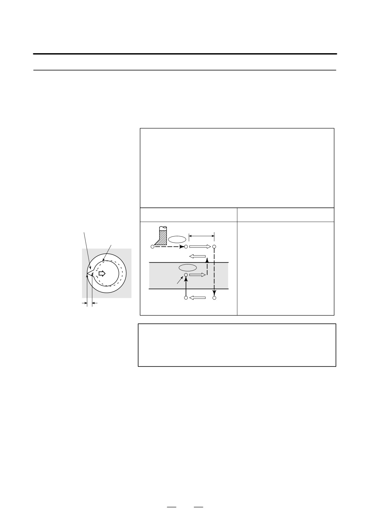
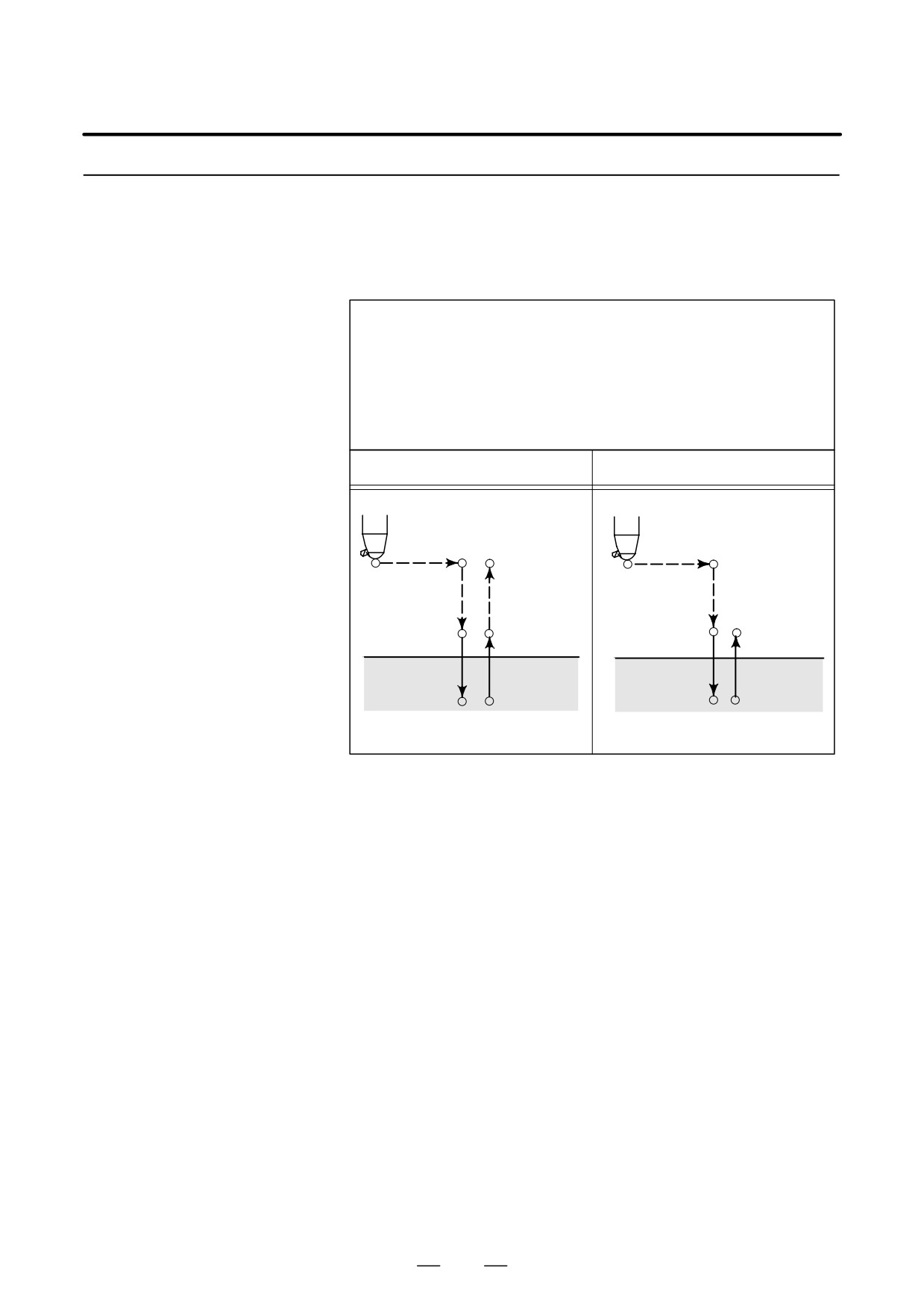
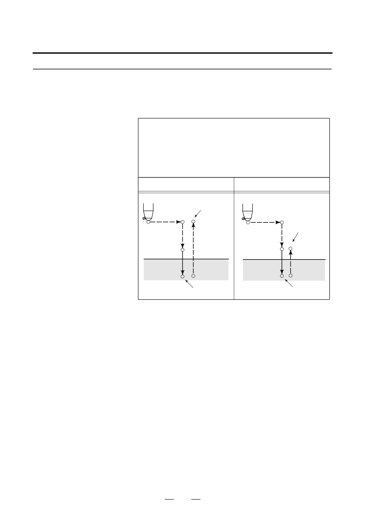
13. FUNCTIONS TO SIMPLIFY
PROGRAMMING
PROGRAMMING
B-63534EN/02
13.1.11
This cycle performs accurate boring.
Back Boring Cycle
(G87)
Format
G87 X_ Y_ Z_ R_ Q_ P_ F_ K_ ;
X_ Y_ : Hole position data
Z_ : The distance from the bottom of the hole to point Z
R_ : The distance from the initial level to point R
(the bottom of the hole) level
Q_ : Tool shift amount
P_ : Dwell time
F_ : Cutting feed rate
K_ : Number of repeats (if required)
G87 (G98)
G87 (G99)
Oriented spindle stop
q
OSS
Tool
Spindle CW
Not used
OSS
Point Z
P
Spindle CW
Shift amount q
Point R
WARNING
Q (shift at the bottom of a hole) is a modal value retained in
canned cycles. It must be specified carefully because it is
also used as the depth of cut for G73 and G83.
212
13. FUNCTIONS TO SIMPLIFY
B-63534EN/02
PROGRAMMING
PROGRAMMING
Explanations
After positioning along the X- and Y-axes, the spindle is stopped at the
fixed rotation position. The tool is moved in the direction opposite to the
tool tip, positioning (rapid traverse) is performed to the bottom of the hole
(point R).
The tool is then shifted in the direction of the tool tip and the spindle is
rotated clockwise. Boring is performed in the positive direction along the
Z-axis until point Z is reached.
At point Z, the spindle is stopped at the fixed rotation position again, the
tool is shifted in the direction opposite to the tool tip, then the tool is
returned to the initial level. The tool is then shifted in the direction of the
tool tip and the spindle is rotated clockwise to proceed to the next block
operation.
Before specifying G87, use a miscellaneous function (M code) to rotate
the spindle.
When the G87 command and an M code are specified in the same block,
the M code is executed at the time of the first positioning operation.
The system then proceeds to the next drilling operation. When K is used
to specify the number of repeats, the M code is executed for the first hole
only; for the second and subsequent holes, the M code is not executed.
When a tool length offset (G43, G44, or G49) is specified in the canned
cycle, the offset is applied at the time of positioning to point R.
Restrictions
D Axis switching
Before the drilling axis can be changed, the canned cycle must be
canceled.
D Boring
In a block that does not contain X, Y, Z, R, or any additional axes, boring
is not performed.
D P/Q
Be sure to specify a positive value in Q. If Q is specified with a negative
value, the sign is ignored. Set the direction of shift in bits 4 (RD1) and
5 (RD2) of parameter No.5101. Specify P and Q in a block that performs
boring. If they are specified in a block that does not perform boring, they
are not stored as modal data.
D Cancel
Do not specify a G code of the 01 group (G00 to G03 or G60 (when the
MDL bit (bit 0 of parameter 5431) is set to 1)) and G87 in a single block.
Otherwise, G87 will be canceled.
D Tool offset
In the canned cycle mode, tool offsets are ignored.
D Subprogram call
In the canned cycle mode, specify the subprogram call command M98P_
in an independent block.
Examples
M3 S500 ;
Cause the spindle to start rotating.
G90 G87 X300. Y-250.
Position, bore hole 1.
Z-120. R-150. Q5.
Orient at the initial level, then shift by 5 mm.
P1000 F120. ;
Stop at point Z for 1 s.
Y-550. ;
Position, drill hole 2.
Y-750. ;
Position, drill hole 3.
X1000. ;
Position, drill hole 4.
Y-550. ;
Position, drill hole 5.
Y-750. ;
Position, drill hole 6
G80 G28 G91 X0 Y0 Z0 ;
Return to the reference position return
M5 ;
Cause the spindle to stop rotating.
213
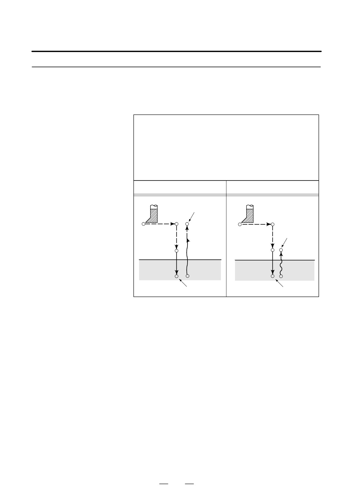
13. FUNCTIONS TO SIMPLIFY
PROGRAMMING
PROGRAMMING
B-63534EN/02
13.1.12
This cycle is used to bore a hole.
Boring Cycle
(G88)
Format
G88 X_ Y_ Z_ R_ P_ F_ K_ ;
X_ Y_ : Hole position data
Z_ : The distance from point R to the bottom of the hole
R_ : The distance from the initial level to point R level
P_ : Dwell time at the bottom of a hole
F_ : Cutting feed rate
K_ : Number of repeats (if required)
G88 (G98)
G88 (G99)
Spindle CW
Initial level
Spindle CW
Point R
Point R
Point R level
Point Z
Point Z
P
P
Spindle stop
Spindle stop
after dwell
after dwell
Explanations
After positioning along the X- and Y-axes, rapid traverse is performed
to point R. Boring is performed from point R to point Z. When boring
is completed, a dwell is performed, then the spindle is stopped. The tool
is manually retracted from the bottom of the hole (point Z) to point R.
At point R, the spindle is rotated clockwise, and rapid traverse is
performed to the initial level.
Before specifying G88, use a miscellaneous function (M code) to rotate
the spindle.
When the G88 command and an M code are specified in the same block,
the M code is executed at the time of the first positioning operation. The
system then proceeds to the next drilling operation.
When K is used to specify the number of repeats, the M code is executed
for the first hole only; for the second and subsequent holes, the M code
is not executed.
When a tool length offset (G43, G44, or G49) is specified in the canned
cycle, the offset is applied at the time of positioning to point R.
214
13. FUNCTIONS TO SIMPLIFY
B-63534EN/02
PROGRAMMING
PROGRAMMING
Limitations
D Axis switching
Before the drilling axis can be changed, the canned cycle must be
canceled.
D Drilling
In a block that does not contain X, Y, Z, R, or any other axes, drilling is
not performed.
D P
Specify P in blocks that perform drilling. If it is specified in a block that
does not perform drilling, it cannot be stored as modal data.
D Cancel
Do not specify a G code of the 01 group (G00 to G03 or G60 (when the
MDL bit (bit 0 of parameter 5431) is set to 1)) and G88 in a single block.
Otherwise, G88 will be canceled.
D Tool offset
In the canned cycle mode, tool offsets are ignored.
D Subprogram call
In the canned cycle mode, specify the subprogram call command M98P_
in an independent block.
Examples
M3 S2000 ;
Cause the spindle to start rotating.
G90 G99 G88 X300. Y-250. Z-150. R-100. P1000 F120. ;
Position, drill hole 1, return to point R
then stop at the bottom of the hole for 1 s.
Y-550. ;
Position, drill hole 2, then return to point R.
Y-750. ;
Position, drill hole 3, then return to point R.
X1000. ;
Position, drill hole 4, then return to point R.
Y-550. ;
Position, drill hole 5, then return to point R.
G98 Y-750. ;
Position, drill hole 6, then return to the initial
level.
G80 G28 G91 X0 Y0 Z0 ; Return to the reference position return
M5 ;
Cause the spindle to stop rotating.
215
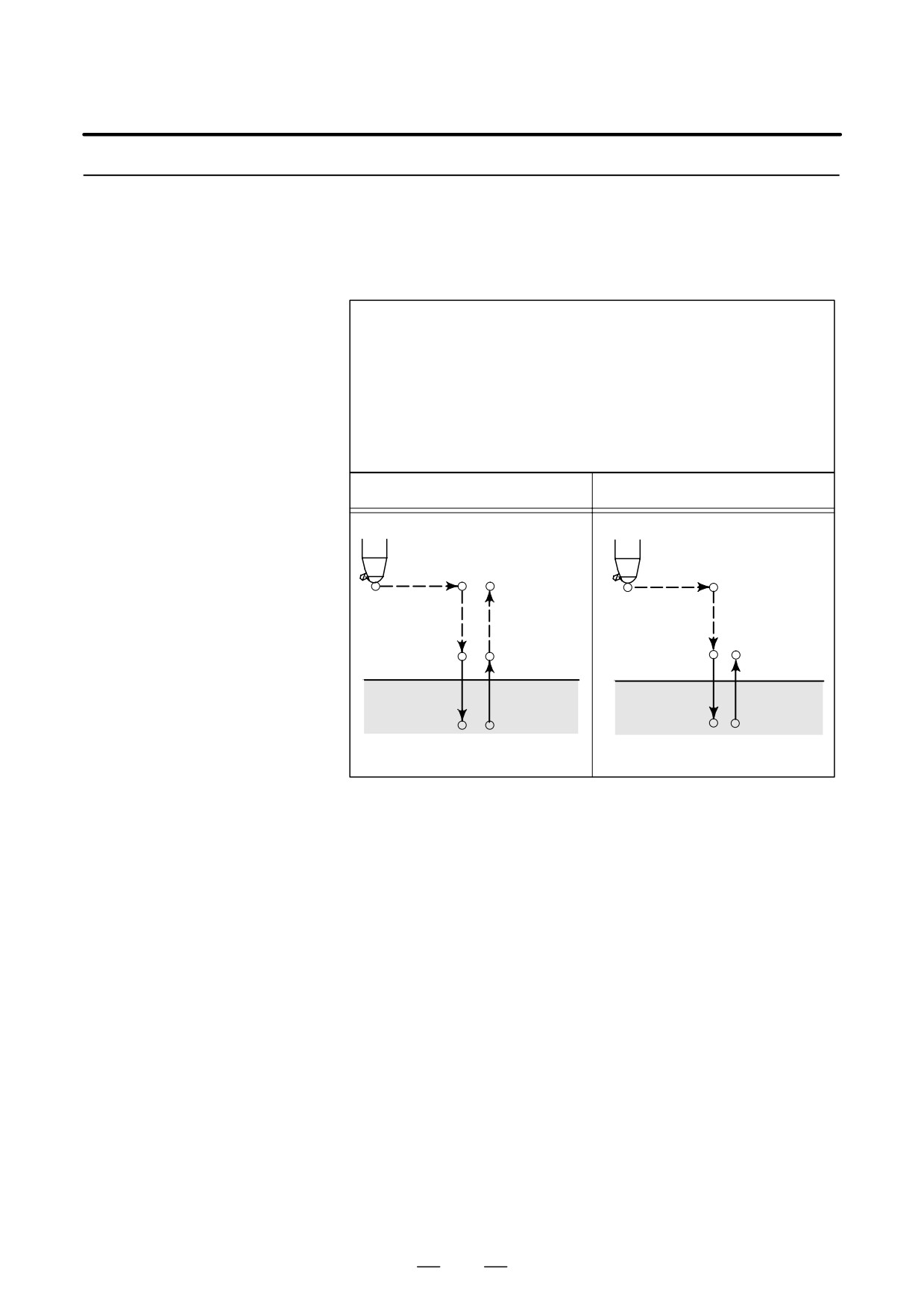
13. FUNCTIONS TO SIMPLIFY
PROGRAMMING
PROGRAMMING
B-63534EN/02
13.1.13
This cycle is used to bore a hole.
Boring Cycle
(G89)
Format
G89 X_ Y_ Z_ R_ P_ F_ K_ ;
X_ Y_ : Hole position data
Z_ : The distance from point R to the bottom of the hole
R_ : The distance from the initial level to point R level
P_ : Dwell time at the bottom of a hole
F_ : Cutting feed rate
K_ : Number of repeats (if required)
G89 (G98)
G89 (G99)
Initial level
Point R level
Point R
Point R
Point Z
Point Z
P
P
Explanations
This cycle is almost the same as G85. The difference is that this cycle
performs a dwell at the bottom of the hole.
Before specifying G89, use a miscellaneous function (M code) to rotate
the spindle.
When the G89 command and an M code are specified in the same block,
the M code is executed at the time of the first positioning operation. The
system then proceeds to the next drilling operation.
When K is used to specify the number of repeats, the M code is executed
for the first hole only; for the second and subsequent holes, the M code
is not executed.
When a tool length offset (G43, G44, or G49) is specified in the canned
cycle, the offset is applied at the time of positioning to point R.
216
13. FUNCTIONS TO SIMPLIFY
B-63534EN/02
PROGRAMMING
PROGRAMMING
Limitations
D Axis switching
Before the drilling axis can be changed, the canned cycle must be
canceled.
D Drilling
In a block that does not contain X, Y, Z, R, or any other axes, drilling is
not performed.
D P
Specify P in blocks that perform drilling. If it is specified in a block that
does not perform drilling, it cannot be stored as modal data.
D Cancel
Do not specify a G code of the 01 group (G00 to G03 or G60 (when the
MDL bit (bit 0 of parameter 5431) is set to 1)) and G89 in a single block.
Otherwise, G89 will be canceled.
D Tool offset
In the canned cycle mode, tool offsets are ignored.
D Subprogram call
In the canned cycle mode, specify the subprogram call command
M98P_in an independent block.
Examples
M3 S100 ;
Cause the spindle to start rotating.
G90 G99 G89 X300. Y-250. Z-150. R-120. P1000 F120. ;
Position, drill hole 1, return to point R
then stop at the bottom of the hole for 1 s.
Y-550. ;
Position, drill hole 2, then return to point R.
Y-750. ;
Position, drill hole 3, then return to point R.
X1000. ;
Position, drill hole 4, then return to point R.
Y-550. ;
Position, drill hole 5, then return to point R.
G98 Y-750. ;
Position, drill hole 6, then return to the initial
level.
G80 G28 G91 X0 Y0 Z0 ; Return to the reference position return
M5 ;
Cause the spindle to stop rotating.
217

13. FUNCTIONS TO SIMPLIFY
PROGRAMMING
PROGRAMMING
B-63534EN/02
13.1.14
G80 cancels canned cycles.
Canned Cycle Cancel
(G80)
Format
G80 ;
Explanations
All canned cycles are canceled to perform normal operation. Point R and
point Z are cleared. This means that R = 0 and Z = 0 in incremental mode.
Other drilling data is also canceled (cleared).
Examples
M3 S100 ;
Cause the spindle to start rotating.
G90 G99 G88 X300. Y-250. Z-150. R-120. F120. ;
Position, drill hole 1, then return to point R.
Y-550. ;
Position, drill hole 2, then return to point R.
Y-750. ;
Position, drill hole 3, then return to point R.
X1000. ;
Position, drill hole 4, then return to point R.
Y-550. ;
Position, drill hole 5, then return to point R.
G98 Y-750. ; Position, drill hole 6, then return to the initial level.
G80 G28 G91 X0 Y0 Z0 ;
Return to the reference position return,
canned cycle cancel
M5 ;
Cause the spindle to stop rotating.
218
13. FUNCTIONS TO SIMPLIFY
B-63534EN/02
PROGRAMMING
PROGRAMMING
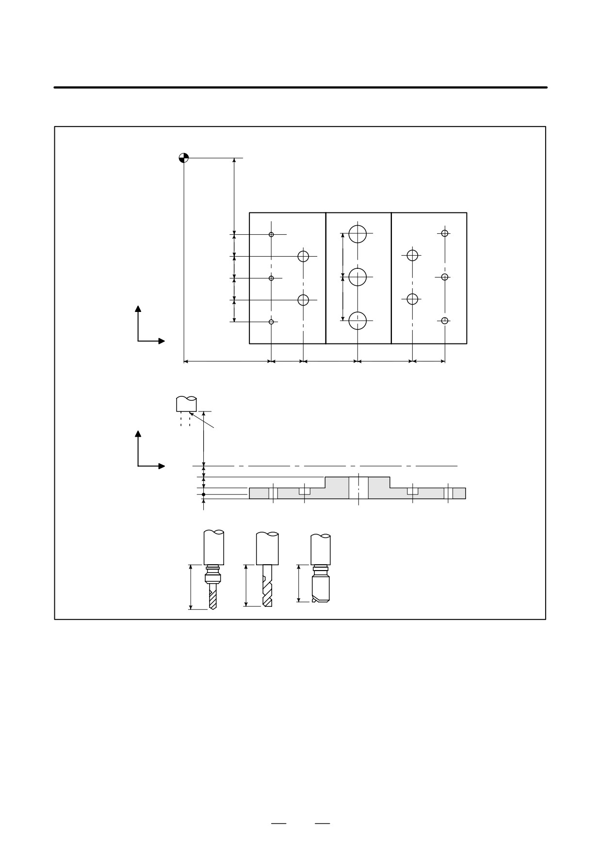
Program example using tool length offset and canned cycles
Reference position
350
#1
#11
#6
100
#7
#10
100
#2
#12
#5
100
#8
#9
Y
200
100
#3
#13
#4
X
400
150
250
250
150
# 11 to 16 Drilling of a 10mm diameter hole
# 17 to 10 Drilling of a 20mm diameter hole
# 11 to 13 Boring of a 95mm diameter hole(depth 50 mm)
Z
Retract position
250
Initial level
X
50
50
30
20
T 11
T 15
T 31
200
190
150
219