FANUC Series 16i/160i/160is-MB, Series 18i/180i/180is-MB5, Series 18i/180i/180is-MB. Operator's Manual - page 7
10. TOOL FUNCTION
(T FUNCTION)
PROGRAMMING
B-63534EN/02
D Tool change type B
and C
Suppose that the tool life management ignore number is 100.
T101;
A tool whose life has not expired is selected from group 1.
(Suppose that tool number 010 is selected.)
M06T102;Tool life counting is performed for the tool in group 1.
(The life of tool number 010 is counted.)
A tool whose life has not expired is selected from group 2.
(Suppose that toolnumber 100 is selected.
M06T103;Tool life counting is lperformed for the tool in group 2.
(The life of tool number 100 is counted.)
A tool whose life has not expired is selected from group 3.
(Suppose that tool number 200 is selected.)
D Tool change type D
Suppose that the tool life management ignore number is 100.
T101M06;A tool whose life has not expired is selected from group 1.
(Suppose that tool number 010 is selected.)
Tool life counting is performed for the tool in group 1.
T102M06;A tool whose life has not expired is selected from group 2.
(Suppose that tool number 100 is selected.)
Tool life counting is performed for the tool in group 2.
(The life of tool number 100 is counted.)
160

10. TOOL FUNCTION
B-63534EN/02
PROGRAMMING
(T FUNCTION)
10.2.4
The life of a tool is specified by a usage frequency (count) or usage time
(in minutes).
Tool Life
Explanations
D Usage count
The usage count is incremented by 1 for each tool used in a program.
In other words, the usage count is incremented by 1 only when the first
tool group number and tool change command are specified after the
CNC unit enters the automatic operation state from the reset state.
CAUTION
Even if the same tool group number is specified more than
once in a program, the usage count is only incremented by
1 and no new tools are selected.
D Usage time
When a tool change is specified (M06), tool life management is started
for the tools specified by the tool group number. In tool life
management, the time during which a tool is used in the cutting mode
is counted in four second increments., If the tool group is changed
before the incremental time of four seconds elapses, the time is not
counted. The time a tool is used for single block stop, feed hold, rapid
traverse, dwell, machine lock, and interlock is not counted.
NOTE
1
When a tool is selected from available tools, tools are
searched starting from the current tool towards the lasttool
to find a tool whose life has not expired. When thelast tool
is reached during this search, the search restartsfrom the
first tool. When it has been determined that there are no
tools whose life has not expired, the last tool is selected.
When the tool currently being used is changed by tool skip
signal, the next new tool is selected using the method
described here.
2
When tool life is counted by time, the life counting can be
overridden using the tool life count override signal. An
override from 0 to 99.9 can be applied. When 0 is specified,
time is not counted. Before the override capability can be
used, bit 2 of parameter LFV No.6801 must be set.
3
When tool life counting indicates that the life of the last tool
in a group has expired, the tool change signal is output.
When tool life is managed by time, the signal is output when
the life of the last tool in the group has expired. When tool
life is managed by usage frequency (count), the signal is
output when the CNC unit is reset or the tool life count
restart M code is specified.
161
11. AUXILIARY FUNCTION
PROGRAMMING
B-63534EN/02
AUXILIARY FUNCTION
11
General
There are two types of auxiliary functions ; miscellaneous function (M
code) for specifying spindle start, spindle stop program end, and so on,
and secondary auxiliary function (B code) for specifying index table
positioning.
When a move command and miscellaneous function are specified in the
same block, the commands are executed in one of the following two
ways:
i) Simultaneous execution of the move command and miscellaneous
function commands.
ii) Executing miscellaneous function commands upon completion of
move command execution.
The selection of either sequence depends on the machine tool builder’s
specification. Refer to the manual issued by the machine tool builder for
details.
162
B-63534EN/02
PROGRAMMING
11. AUXILIARY FUNCTION
11.1
When a numeral is specified following address M, code signal and a
strobe signal are sent to the machine. The machine uses these signals to
AUXILIARY
turn on or off its functions.
FUNCTION
Usually, only one M code can be specified in one block. In some cases,
(M FUNCTION)
however, up to three M codes can be specified for some types of machine
tools.
Which M code corresponds to which machine function is determined by
the machine tool builder.
The machine processes all operations specified by M codes except those
specified by M98, M99,M198 or called subprogram(Parameter No.6071
to 6079), or called custom macro (Parameter No.6080 to 6089). Refer to
the machine tool builder’s instruction manual for details.
Explanations
The following M codes have special meanings.
D M02,M03
This indicates the end of the main program
(End of program)
Automatic operation is stopped and the CNC unit is reset.
This differs with the machine tool builder.
After a block specifying the end of the program is executed,
control returns to the start of the program.
Bit 5 of parameter 3404 (M02) or bit 4 of parameter 3404 (M30) can be
used to disable M02, M30 from returning control to the start of the
program.
D M00
Automatic operation is stopped after a block containing M00 is executed.
(Program stop)
When the program is stopped, all existing modal information remains
unchanged. The automatic operation can be restarted by actuating the
cycle operation. This differs with the machine tool builder.
D M01
Similarly to M00, automatic operation is stopped after a block containing
(Optional stop)
M01 is executed. This code is only effective when the Optional Stop
switch on the machine operator’s panel has been pressed.
D M98
This code is used to call a subprogram. The code and strobe signals are
(Calling of sub-
not sent. See the subprogram II- 12.3 for details .
program)
D M99
This code indicates the end of a subprogram.
(End of subprogram)
M99 execution returns control to the main program. The code and strobe
signals are not sent. See the subprogram section 12.3 for details.
D M198 (Calling a
This code is used to call a subprogram of a file in the external input/output
subprogram)
function. See the description of the subprogram call function (III-4.7) for
details.
NOTE
The block following M00, M01, M02, or M30 is not pre-read
(buffered). Similarly, ten M codes which do not buffer can
be set by parameters (Nos. 3411 to 3420). Refer to the
machine tool builder’s instruction manual for these M codes.
163

11. AUXILIARY FUNCTION
PROGRAMMING
B-63534EN/02
In general, only one M code can be specified in a block. However, up to
11.2
three M codes can be specified at once in a block by setting bit 7 (M3B)
MULTIPLE M
of parameter No. 3404 to 1. Up to three M codes specified in a block are
COMMANDS IN A
simultaneously output to the machine. This means that compared with
the conventional method of a single M command in a single block, a
SINGLE BLOCK
shorter cycle time can be realized in machining.
Explanations
CNC allows up to three M codes to be specified in one block.
However, some M codes cannot be specified at the same time due to
mechanical operation restrictions. For detailed information about the
mechanical operation restrictions on simultaneous specification of
multiple M codes in one block, refer to the manual of each machine
tool builder.
M00, M01, M02, M30, M98, M99, or M198 must not be specified
together with another M code.
Some M codes other than M00, M01, M02, M30, M98, M99, and
M198 cannot be specified together with other M codes; each of those
M codes must be specified in a single block.
Such M codes include these which direct the CNC to perform internal
operations in addition to sending the M codes themselves to the
machine. To be specified, such M codes are M codes for calling
program numbers 9001 to 9009 and M codes for disabling advance
reading (buffering) of subsequent blocks. Meanwhile, multiple of M
codes that direct the CNC only to send the M codes themselves
(without performing internal operations ) can be specified in a single
block.
Examples
One M command
Multiple M commands
in a single block
in a single block
M40 ;
M40M50M60 ;
M50 ;
G28G91X0Y0Z0 ;
M60 ;
:
G28G91X0Y0Z0 ;
:
:
:
:
:
:
:
164
B-63534EN/02
PROGRAMMING
11. AUXILIARY FUNCTION
The M code group check function checks if a combination of multiple M
11.3
codes (up to three M codes) contained in a block is correct.
M CODE GROUP
This function has two purposes. One is to detect if any of the multiple M
CHECK FUNCTION
codes specified in a block include an M code that must be specified alone.
The other purpose is to detect if any of the multiple M codes specified in
a block include M codes that belong to the same group. In either of these
cases, P/S alarm No. 5016 is issued.
For details on group data setting, refer to the manual available from the
machine tool builder.
Explanations
D M code setting
Up to 500 M codes can be specified. In general, M0 to M99 are
always specified. M codes from M100 and up are optional.
D Group numbers
Group numbers can be set from 0 to 127. Note, however, that 0 and 1
have special meanings. Group number 0 represents M codes that need
not be checked. Group number 1 represents M codes that must be
specified alone.
165
11. AUXILIARY FUNCTION
PROGRAMMING
B-63534EN/02
Indexing of the table is performed by address B and a following 8-digit
11.4
number. The relationship between B codes and the corresponding
THE SECOND
indexing differs between machine tool builders.
AUXILIARY
Refer to the manual issued by the machine tool builder for details.
FUNCTIONS
(B CODES)
Explanations
D Valid data range
0 to 99999999
D Specification
1. To enable the use of a decimal point, set bit 0 (AUP) of parameter
No.3450 to 1.
Command Output value
B10.
10000
B10
10
2. Use bit 0 (DPI) of parameter No. 3401 to specify whether the
magnification for B output will be
1000 or
1 when a decimal
point is omitted.
Command Output value
DPI=1
B1
1000
DPI=0
B1
1
3. Use bit 0 (AUX) of parameter No. 3405 to specify whether the
magnification for B output will be
1000 or
10000 when a
decimal point is omitted for the inch Input system
(only when DPI=1).
Command Output value
AUX=1
B1
10000
AUX=0
B1
1000
Restrictions
Addresses used for the second auxiliary functions (addresses specified
with B or parameter No. 3460) cannot be used as controlled axis names
(parameter No. 1020).
166
B-63534EN/02
PROGRAMMING
12. PROGRAM CONFIGURATION
PROGRAM CONFIGURATION
12
General
D Main program and
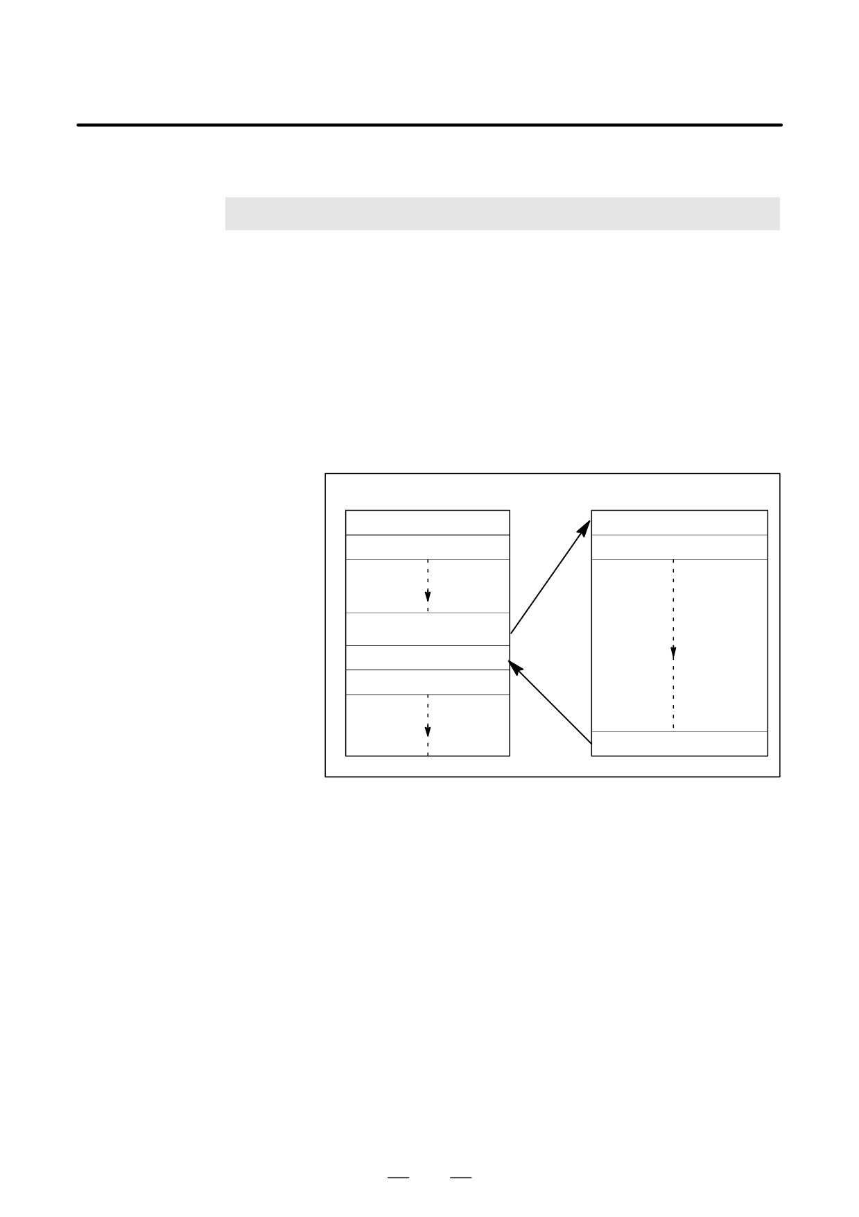
There are two program types, main program and subprogram. Normally,
subprogram
the CNC operates according to the main program. However, when a
command calling a subprogram is encountered in the main program,
control is passed to the subprogram. When a command specifying a
return to the main program is encountered in a subprogram, control is
returned to the main program.
Main program
Subprogram
Instruction 1
Instruction 1Ȁ
Instruction 2
Instruction 2Ȁ
Follow the direction of the
subprogram
Instruction n
Instruction n+1
Return to the main program
Fig. 12 (a) Main program and Subprogram
The CNC memory can hold up to 400 main programs and subprograms
(63 as standard). A main program can be selected from the stored main
programs to operate the machine. See III-9.3 or III-10 in OPERATION
for the methods of registering and selecting programs.
167
12. PROGRAM CONFIGURATION
PROGRAMMING
B-63534EN/02
D Program components
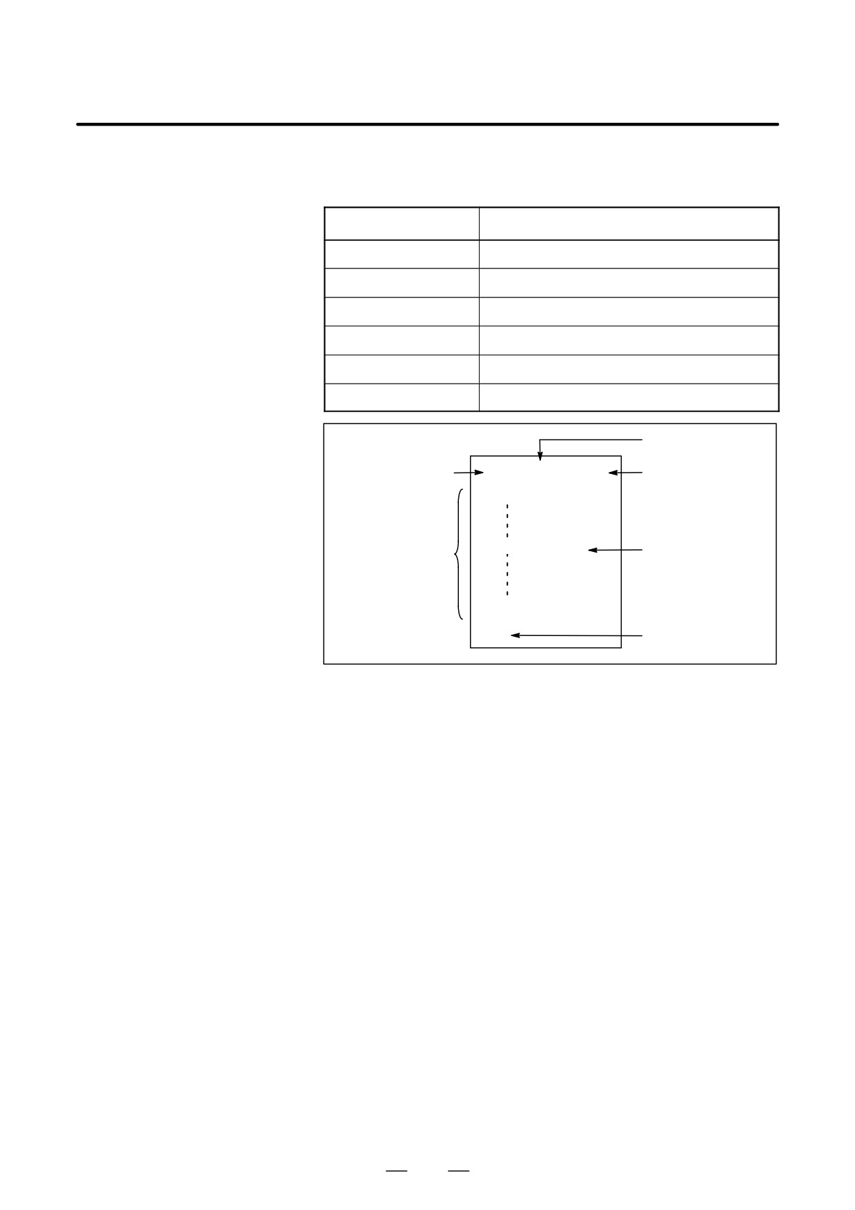
A program consists of the following components:
Table 12 Program components
Components
Descriptions
Tape start
Symbol indicating the start of a program file
Leader section
Used for the title of a program file, etc.
Program start
Symbol indicating the start of a program
Program section
Commands for machining
Comment section
Comments or directions for the operator
Tape end
Symbol indicating the end of a program file
Leader section
Tape start
% TITLE
;
Program start
O0001 ;
(COMMENT)
Program section
Comment section
M30 ;
%
Tape end
Fig. 12 (b) Program configuration
D Program section
A program section consists of several blocks. A program section starts
configuration
with a program number and ends with a program end code.
Program section
Program section
configuration
Program number
O0001 ;
Block 1
N1 G91 G00 X120.0 Y80.0 ;
Block 2
N2 G43 Z-32.0 H01 ;
:
:
Block n
Nn Z0 ;
Program end
M30 ;
A block contains information necessary for machining, such as a move
command or coolant on/off command.Specifying a slash (/) at the start
of a block disables the execution of some blocks (see “optional block
skip” in II-12.2).
168
B-63534EN/02
PROGRAMMING
12. PROGRAM CONFIGURATION
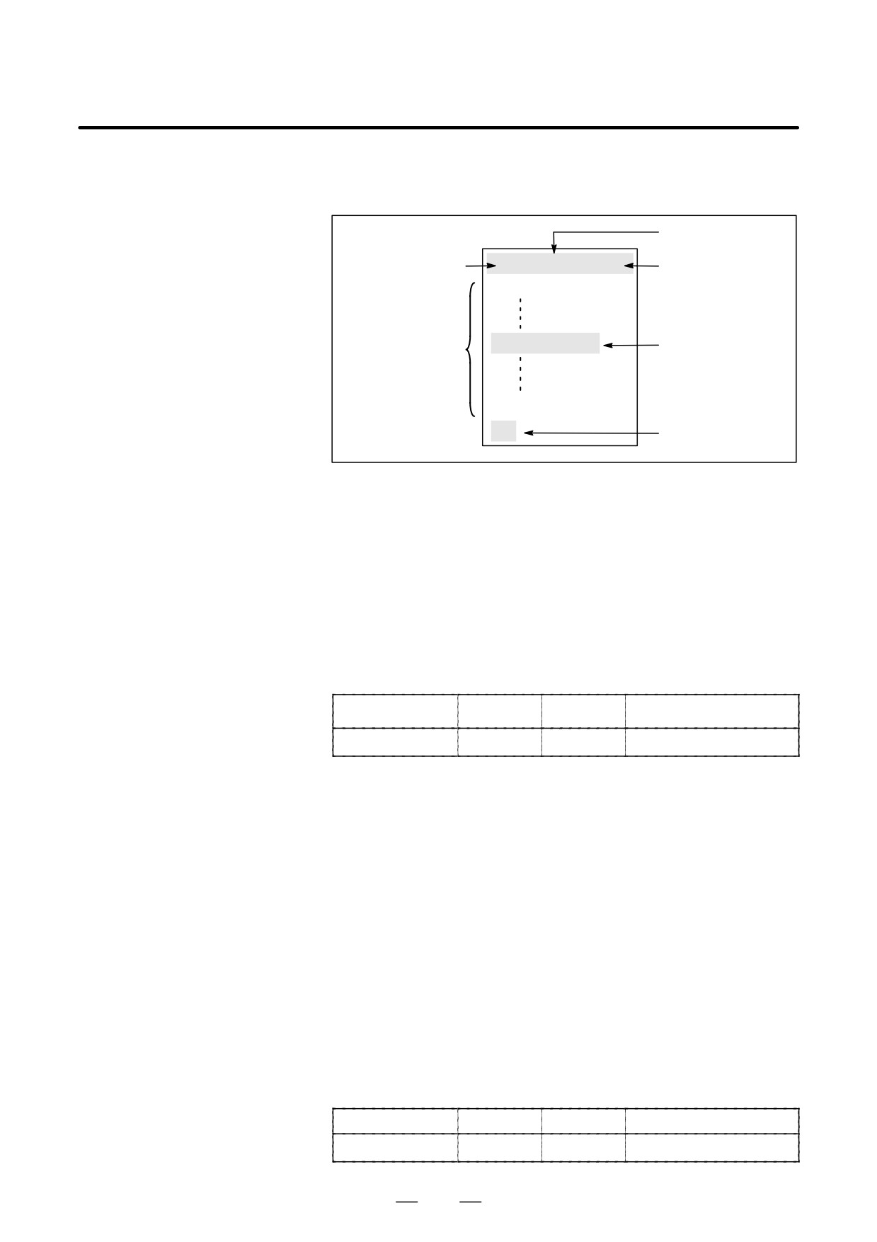
This section describes program components other than program sections.
12.1
See II-12.2 for a program section.
PROGRAM
COMPONENTS
Leader section
OTHER THAN
Tape start
% TITLE
;
Program start
PROGRAM
O0001 ;
SECTIONS
(COMMENT)
Comment section
Program section
M30 ;
%
Tape end
Fig. 12.1 (a) Program configuration
Explanations
D Tape start
The tape start indicates the start of a file that contains NC programs.
The mark is not required when programs are entered using SYSTEM P
or ordinary personal computers. The mark is not displayed on the screen.
However, if the file is output,the mark is automatically output at the start
of the file.
Table 12.1 (a) Code of a tape start
Name
ISO code
EIA code
Notation in this manual
Tape start
%
ER
%
D Leader section
Data entered before the programs in a file constitutes a leader section.
When machining is started, the label skip state is usually set by turning
on the power or resetting the system. In the label skip state, all
information is ignored until the first end-of-block code is read. When a
file is read into the CNC unit from an I/O device, leader sections are
skipped by the label skip function.
A leader section generally contains information such as a file header.
When a leader section is skipped, even a TV parity check is not made. So
a leader section can contain any codes except the EOB code.
D Program start
The program start code is to be entered immediately after a leader section,
that is, immediately before a program section.
This code indicates the start of a program, and is always required to
disable the label skip function.
With SYSTEM P or ordinary personal computers, this code can be entered
by pressing the return key.
Table 12.1 (b) Code of a program start
Name
ISO code
EIA code
Notation in this manual
Program start
LF
CR
;
169
12. PROGRAM CONFIGURATION
PROGRAMMING
B-63534EN/02
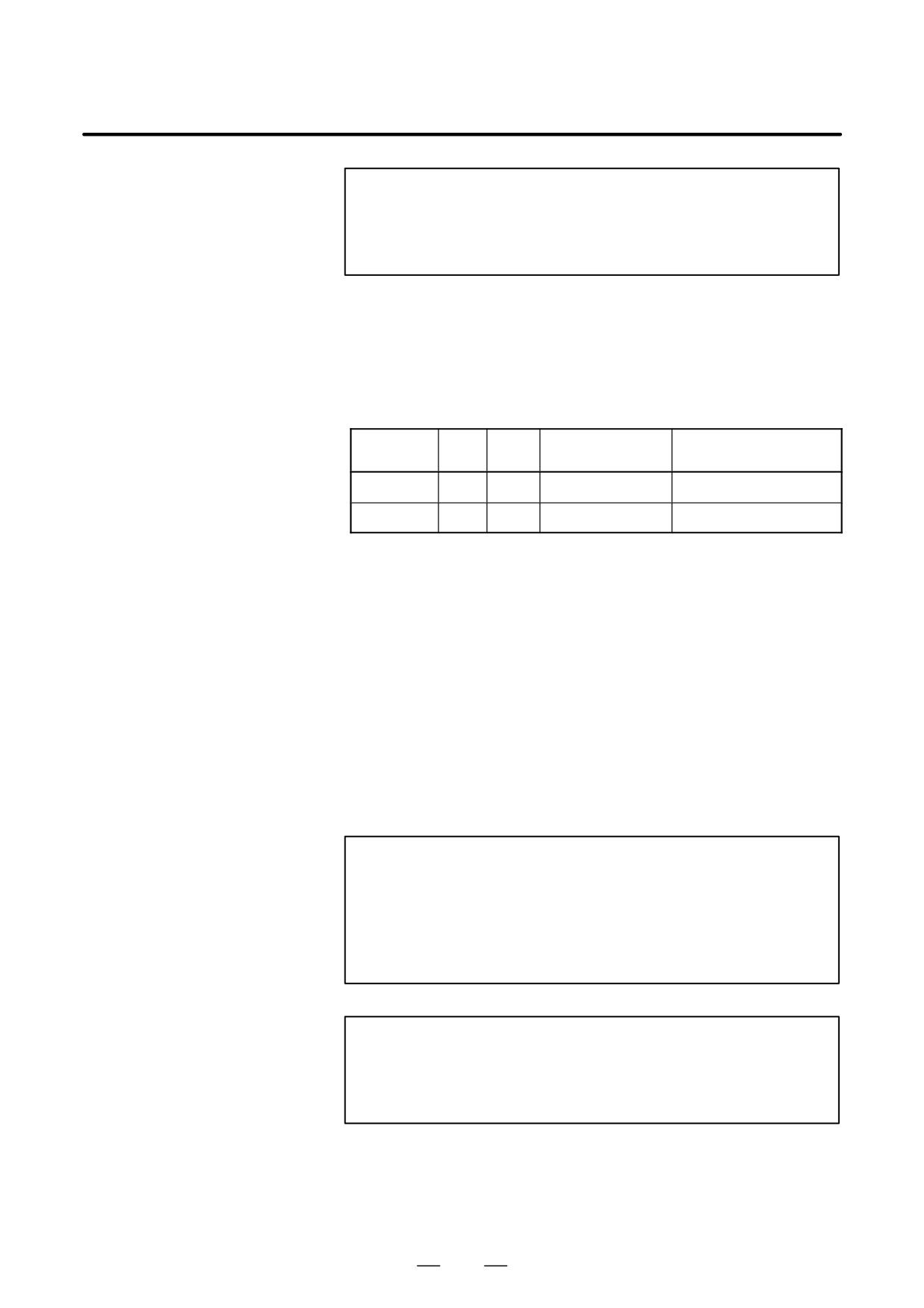
NOTE
If one file contains multiple programs, the EOB code for
label skip operation must not appear before a second or
subsequent program number.
D Comment section
Any information enclosed by the control-out and control-in codes is
regarded as a comment.
The user can enter a header, comments, directions to the operator, etc. in
a comment section.
Table 12.1 (c) Codes of a control-in and a control-out
ISO
EIA
Notation in this
Name
Meaning
code
code
manual
Control-out
(
2-4-5
(
Start of comment section
Control-in
)
2-4-7
)
End of comment section
When a program is read into memory for memory operation, comment
sections, if any, are not ignored but are also read into memory. Note,
however, that codes other than those listed in the code table in Appendix
A are ignored, and thus are not read into memory.
When data in memory is output on external I/O device(See III-8), the
comment sections are also output.
When a program is displayed on the screen, its comment sections are also
displayed. However, those codes that were ignored when read into
memory are not output or displayed.
During memory operation or DNC operation, all comment sections are
ignored.
The TV check function can be used for a comment section by setting
parameter CTV (bit 1 of No. 0100).
CAUTION
If a long comment section appears in the middle of a
program section, a move along an axis may be suspended
for a long time because of such a comment section. So a
comment section should be placed where movement
suspension may occur or no movement is involved.
NOTE
1
If only a control-in code is read with no matching
control-out code, the read control-in code is ignored.
2
The EOB code cannot be used in a comment.
170
B-63534EN/02
PROGRAMMING
12. PROGRAM CONFIGURATION
D Tape end
A tape end is to be placed at the end of a file containing NC programs.
If programs are entered using the automatic programming system, the
mark need not be entered.
The mark is not displayed on the screen. However, when a file is output,
the mark is automatically output at the end of the file.
If an attempt is made to execute % when M02 or M03 is not placed at the
end of the program, the P/S alarm (No. 5010) is occurred.
Table 12.1 (d) Code of a tape end
Name
ISO code
EIA code
Notation in this manual
Tape end
%
ER
%
171
12. PROGRAM CONFIGURATION
PROGRAMMING
B-63534EN/02
This section describes elements of a program section. See II-12.1 for
12.2
program components other than program sections.
PROGRAM SECTION
CONFIGURATION
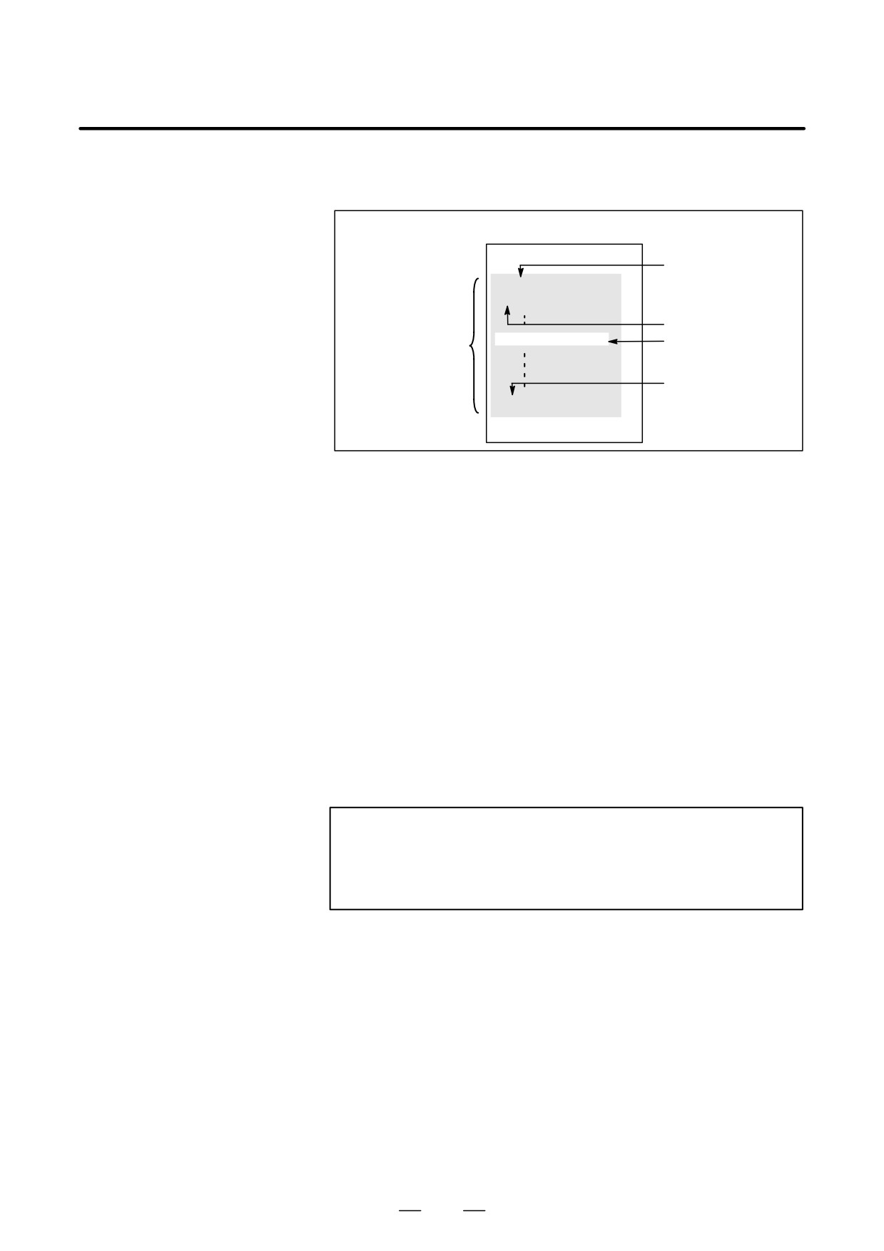
% TITLE;
Program number
O0001 ;
N1 … ;
Sequence number
(COMMENT)
Comment section
Program section
Program end
M30 ;
%
Fig. 12.2 (a) Program configuration
D Program number
A program number consisting of address O followed by a four-digit
number is assigned to each program at the beginning registered in
memory to identify the program.
In ISO code, the colon ( : ) can be used instead of O.
When no program number is specified at the start of a program, the
sequence number (N
) at the start of the program is regarded as its
program number. If a five-digit sequence number is used, the lower four
digits are registered as a program number. If the lower four digits are all
0, the program number registered immediately before added to 1 is
registered as a program number. Note, however, that N0 cannot be used
for a program number.
If there is no program number or sequence number at the start of a
program, a program number must be specified using the MDI panel when
the program is stored in memory (See III-8.4 or III-10.1)
NOTE
Program numbers 8000 to 9999 may be used by machine
tool builders, and the user may not be able to use these
numbers.
172

B-63534EN/02
PROGRAMMING
12. PROGRAM CONFIGURATION
D Sequence number and
A program consists of several commands. One command unit is called a
block
block. One block is separated from another with an EOB of end of block
code.
Table 12.2 (a) EOB code
Name
ISO code
EIA code
Notation in this manual
End of block (EOB)
LF
CR
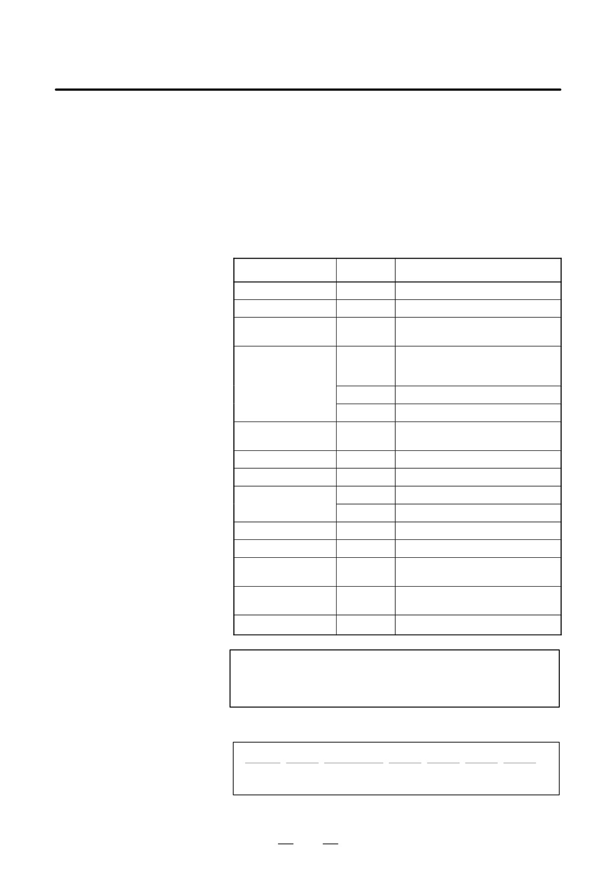
;
At the head of a block, a sequence number consisting of address N
followed by a number not longer than five digits (1 to 99999) can be
placed. Sequence numbers can be specified in a random order, and any
numbers can be skipped. Sequence numbers may be specified for all
blocks or only for desired blocks of the program. In general, however, it
is convenient to assign sequence numbers in ascending order in phase
with the machining steps (for example, when a new tool is used by tool
replacement, and machining proceeds to a new surface with table
indexing.)
N300 X200.0 Z300.0 ; A sequence number is underlined.
Fig. 12.2 (b) Sequence number and block (example)
NOTE
N0 must not be used for the reason of file compatibility with
other CNC systems.
Program number 0 cannot be used. So 0 must not be used
for a sequence number regarded as a program number.
D TV check (Vertical parity
A parity check is made for a block on input tape vertically. If the number
check along tape)
of characters in one block (starting with the code immediately after an
EOB and ending with the next EOB) is odd, an P/S alarm (No.002) is
output. No TV check is made only for those parts that are skipped by the
label skip function. Bit 1 (CTV) of parameter No. 0100 is used to specify
whether comments enclosed in parentheses are counted as characters
during TV check. The TV check function can be enabled or disabled by
setting on the MDI unit (See III-11.4.3.).
173
12. PROGRAM CONFIGURATION
PROGRAMMING
B-63534EN/02
D Block configuration
A block consists of one or more words. A word consists of an address
(word and address)
followed by a number some digits long. (The plus sign (+) or minus sign
(-) may be prefixed to a number.)
Word = Address + number (Example : X-1000)
For an address, one of the letters (A to Z) is used ; an address defines the
meaning of a number that follows the address. Table 12.2 (b) indicates
the usable addresses and their meanings.
The same address may have different meanings, depending on the
preparatory function specification.
Table 12.2 (b) Major functions and addresses
Function
Address
Meaning
Program number
O (*1)
Program number
Sequence number
N
Sequence number
Preparatory function
G
Specifies a motion mode (linear, arc,
etc.)
Dimension word
X, Y, Z, U,
Coordinate axis move command
V, W, A, B,
C
I, J, K
Coordinate of the arc center
R
Arc radius
Feed function
F
Rate of feed per minute,
Rate of feed per revolution
Spindle speed function
S
Spindle speed
Tool function
T
Tool number
Auxiliary function
M
On/off control on the machine tool
B
Table indexing, etc.
Offset number
D, H
Offset number
Dwell
P, X
Dwell time
Program number
P
Subprogram number
designation
Number of
P
Number of subprogram repetitions
repetitions
Parameter
P, Q
Canned cycle parameter
NOTE
(*1) In ISO code, the colon ( : ) can also be used as the address
of a program number.
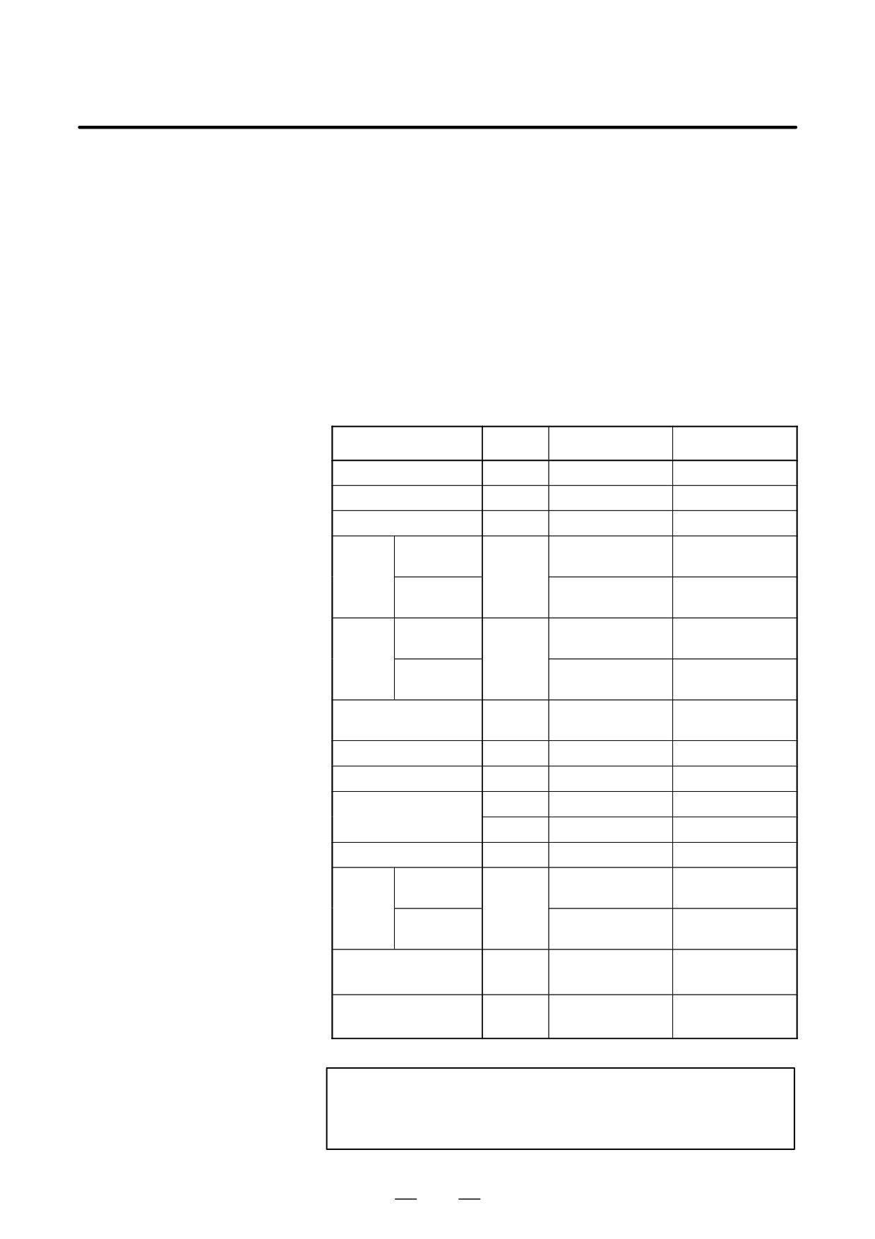
N_
G_
X_ Y_
F_
S_
T_
M_
;
Spindle
Sequence Preparatory
Dimension Feed-
Tool
Miscellaneous
speed
number
function
word
function
function
function
function
Fig. 12.2 (c) 1 block (example)
174
B-63534EN/02
PROGRAMMING
12. PROGRAM CONFIGURATION
D Major addresses and
Major addresses and the ranges of values specified for the addresses are
ranges of command
shown below. Note that these figures represent limits on the CNC side,
values
which are totally different from limits on the machine tool side. For
example, the CNC allows a tool to traverse up to about 100 m (in
millimeter input) along the X axis.
However, an actual stroke along the X axis may be limited to 2 m for a
specific machine tool.
Similarly, the CNC may be able to control a cutting federate of up to 240
m/min, but the machine tool may not allow more than 3 m/min. When
developing a program, the user should carefully read the manuals of the
machine tool as well as this manual to be familiar with the restrictions on
programming.
Table 12.2 (c) Major addresses and ranges of command values
Function
Address
Input in mm
Input in inch
Program number
O (*1)
1-9999
1-9999
Sequence number
N
1-99999
1-99999
Preparatory function
G
0-99
0-99
Dimen-
Increment
X, Y, Z,
99999.999mm
9999.9999inch
sion
system IS-B
U, V, W,
word
A, B, C,
Increment
9999.9999mm
999.99999inch
I, J, K, R,
system IS-C
Feed
Increment
F
1-240000mm/min
0.01-9600.00
per
system IS-B
inch/min
minute
Increment
1-100000mm/min
0.01-4000.00
system IS-C
inch/min
Feed per revolution
F
0.001-500.00
0.0001-9.9999
mm/rev
inch/rev
Spindle speed function
S
0-20000
0-20000
Tool function
T
0-99999999
0-99999999
Auxiliary function
M
0-99999999
0-99999999
B
0-99999999
0-99999999
Offset number
H, D
0-400
0-400
Dwell
Increment
X, P
0-99999.999s
0-99999.999s
system IS-B
Increment
0-9999.9999s
0-9999.9999s
system IS-C
Designation of a pro-
P
1-9999
1-9999
gram number
Number of subprogram
P
1-999
1-999
repetitions
NOTE
(*1) In ISO code, the colon ( : ) can also be used as the address
of a program number.
175

12. PROGRAM CONFIGURATION
PROGRAMMING
B-63534EN/02
D Optional block skip
When a slash followed by a number (/n (n=1 to 9)) is specified at the head
of a block, and optional block skip switch n on the machine operator panel
is set to on, the information contained in the block for which
/n
corresponding to switch number n is specified is ignored in DNC
operation or memory operation.
When optional block skip switch n is set to off, the information contained
in the block for which /n is specified is valid. This means that the operator
can determine whether to skip the block containing /n.
Number 1 for /1 can be omitted. However, when two or more optional
block skip switches are used for one block, number 1 for /1 cannot be
omitted.
Example)
(Incorrect)
(Correct)
//3 G00X10.0;
/1/3 G00X10.0;
This function is ignored when programs are loaded into memory. Blocks
containing /n are also stored in memory, regardless of how the optional
block skip switch is set.
Programs held in memory can be output, regardless of how the optional
block skip switches are set.
Optional block skip is effective even during sequence number search
operation.
Depending on the machine tool, all optional block skip switches (1 to 9)
may not be usable. Refer to manuals of the machine tool builder to find
which switches are usable.
WARNING
1
Position of a slash
A slash (/) must be specified at the head of a block. If a slash
is placed elsewhere, the information from the slash to
immediately before the EOB code is ignored.
2 Disabling an optional block skip switch
Optional block skip operation is processed when blocks are
read from memory or tape into a buffer. Even if a switch is
set to on after blocks are read into a buffer, the blocks
already read are not ignored.
NOTE
TV and TH check
When an optional block skip switch is on. TH and TV checks
are made for the skipped portions in the same way as when
the optional block skip switch is off.
176

B-63534EN/02
PROGRAMMING
12. PROGRAM CONFIGURATION
D Program end
The end of a program is indicated by programming one of the following
codes at the end of the program:
Table 12.2 (d) Code of a program end
Code
Meaning usage
M02
For main program
M30
M99
For subprogram
If one of the program end codes is executed in program execution, the
CNC terminates the execution of the program, and the reset state is set.
When the subprogram end code is executed, control returns to the
program that called the subprogram.
WARNING
A block containing an optional block skip code such as /M02
; , /M30 ; , or /M99 ; is not regarded as the end of a program,
if the optional block skip switch on the machine operator’s
panel is set to on.
(See “Optional block skip”.)
177
12. PROGRAM CONFIGURATION
PROGRAMMING
B-63534EN/02
12.3
If a program contains a fixed sequence or frequently repeated pattern, such
a sequence or pattern can be stored as a subprogram in memory to simplify
SUBPROGRAM
the program.
(M98, M99)
A subprogram can be called from the main program.
A called subprogram can also call another subprogram.
Format
D Subprogram
configuration
One subprogram
O jjjj ;
Subprogram number
(or the colon (:) optionally in the case of ISO)
M99 ;
Program end
M99 need not constitute a separate block as indicated below.
Example) X100.0 Y100.0 M99 ;
D Subprogram call
M98 P fff ffff ;
↑
↑
Number of times
Subprogram number
the subprogram is
called repeatedly
When no repetition data is specified, the subprogram is called just once.
Explanations
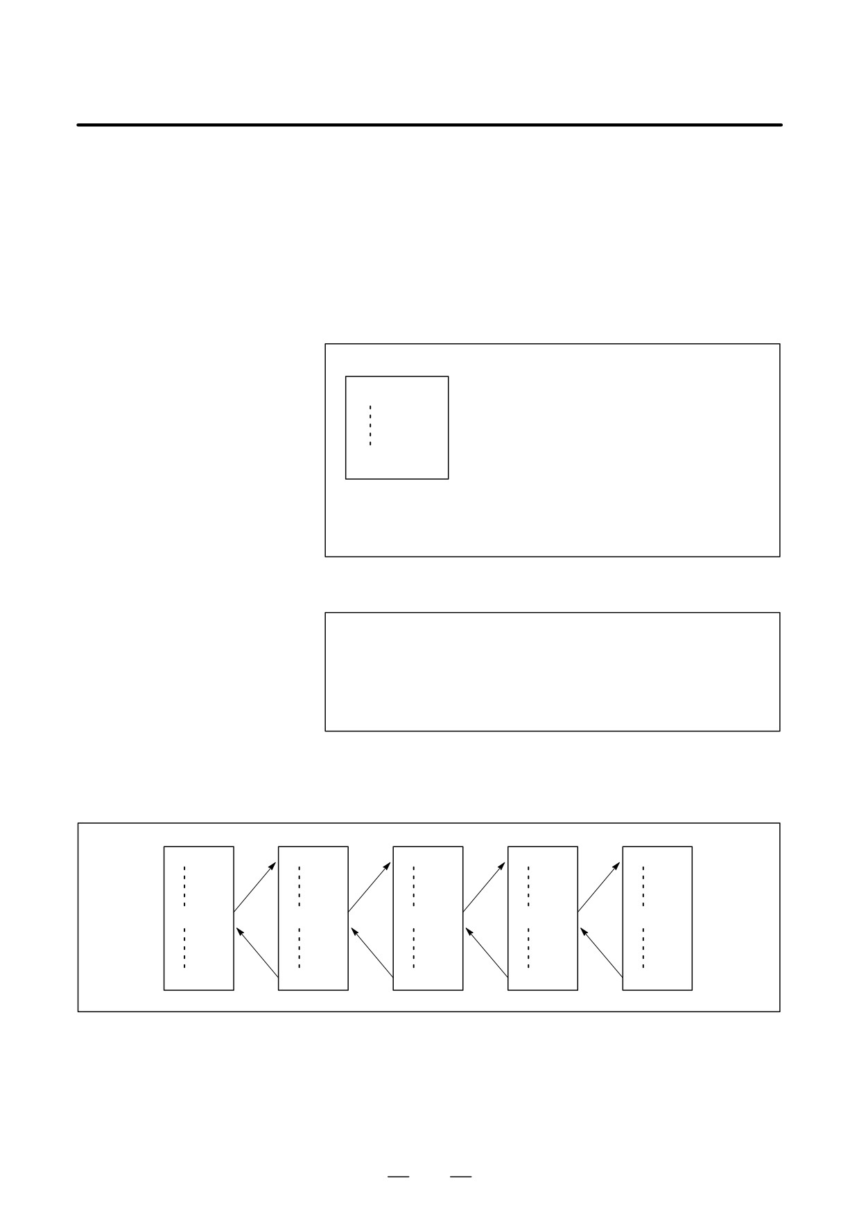
When the main program calls a subprogram, it is regarded as a one-level
subprogram call. Thus, subprogram calls can be nested up to four levels
as shown below.
Main program
Subprogram
Subprogram
Subprogram
Subprogram
O0001 ;
O1000 ;
O2000 ;
O3000 ;
O4000 ;
M98P1000 ;
M98P2000 ;
M98P3000 ;
M98P4000 ;
M30 ;
M99 ;
M99 ;
M99 ;
M99 ;
(One-level nesting)
(Two-level nesting)
(Three-level nesting)
(Four-level nesting)
A single call command can repeatedly call a subprogram up to 999 times.
For compatibility with automatic programming systems, in the first
block, Nxxxx can be used instead of a subprogram number that follows
O (or :). A sequence number after N is registered as a subprogram number.
D Reference
See III-10 for the method of registering a subprogram.
178
B-63534EN/02
PROGRAMMING
12. PROGRAM CONFIGURATION
NOTE
1
The M98 and M99 code signal and strobe signal are not
output to the machine tool.
2
If the subprogram number specified by address P cannot be
found, an alarm (No. 078) is output.
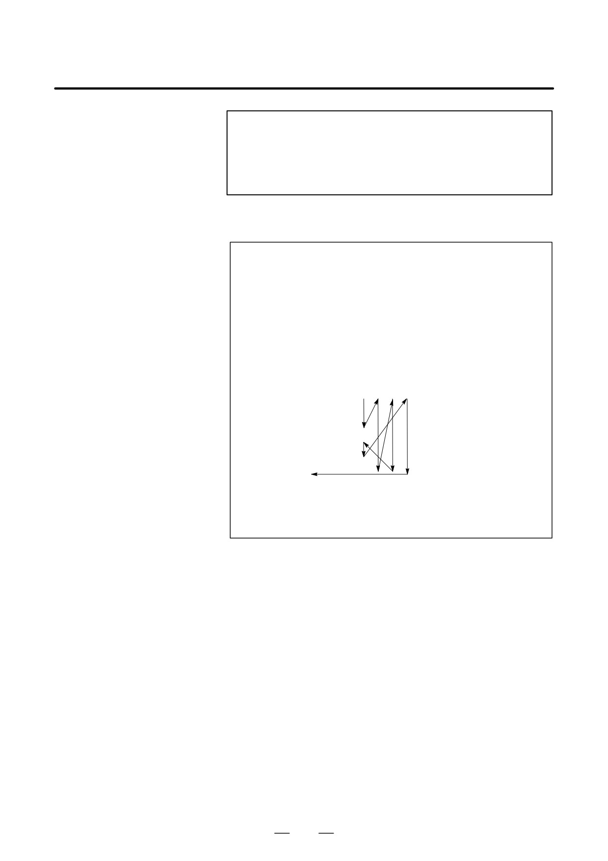
Examples
l M98 P51002 ;
This command specifies ”Call the subprogram (number 1002) five times in
succession.” A subprogram call command (M98P_) can be specified in the
same block as a move command.
l X1000.0 M98 P1200 ;
This example calls the subprogram (number 1200) after an X movement.
l Execution sequence of subprograms called from a main program
Main program
Subprogram
1
2
3
N0010 … ;
O1010 … ;
N0020 … ;
N1020 … ;
N0030 M98 P21010 ;
N1030 … ;
N0040 … ;
N1040 … ;
N0050 M98 P1010 ;
N1050 … ;
N0060 … ;
N1060 … M99 ;
A subprogram can call another subprogram in the same way as a main pro-
gram calls a subprogram.
179
12. PROGRAM CONFIGURATION
PROGRAMMING
B-63534EN/02
Special Usage
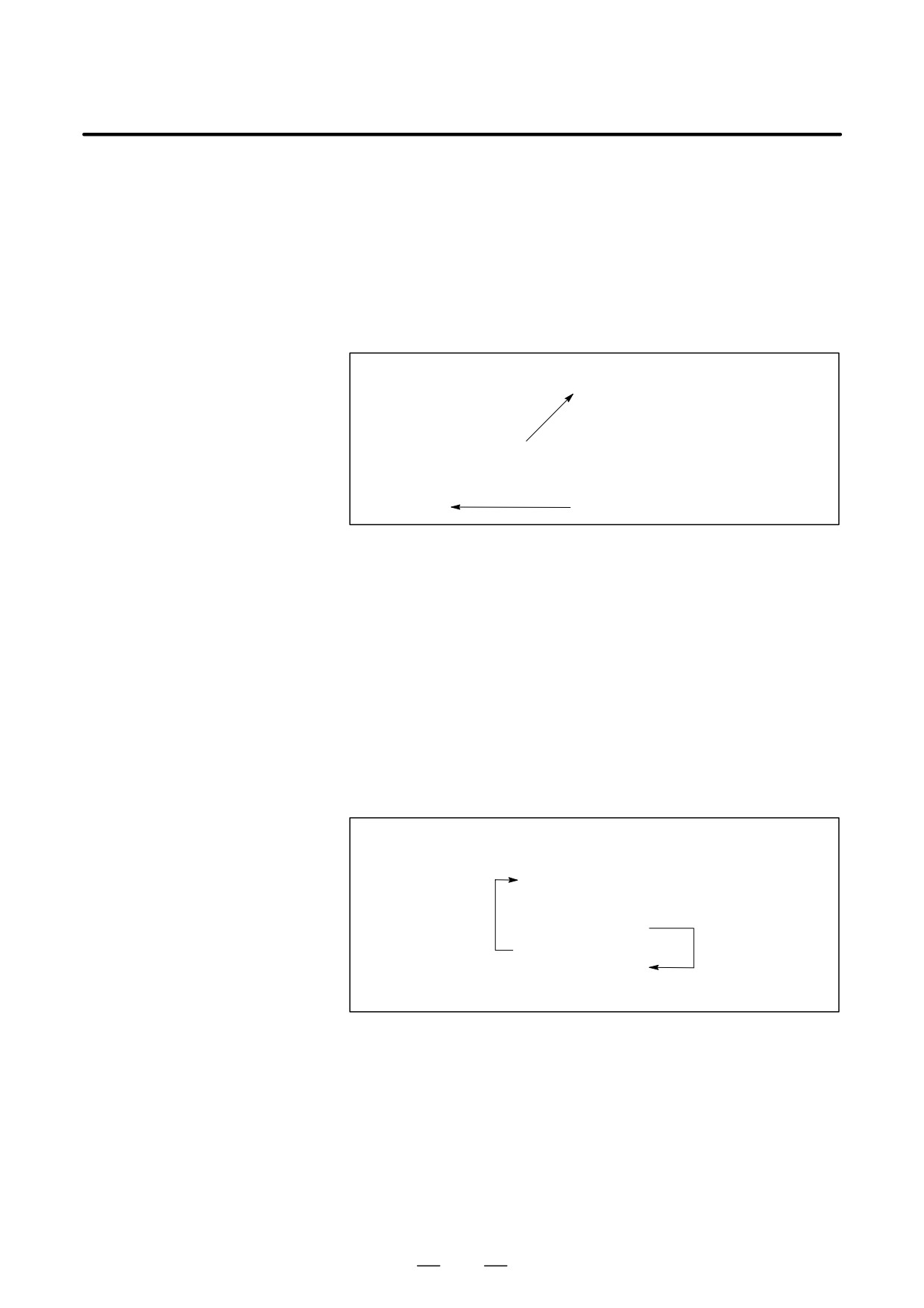
D Specifying the sequence
If P is used to specify a sequence number when a subprogram is
number for the return
terminated, control does not return to the block after the calling block, but
destination in the main
returns to the block with the sequence number specified by P. Note,
program
however, that P is ignored if the main program is operating in a mode other
than memory operation mode.
This method consumes a much longer time than the normal return method
to return to the main program.
Main program
Subprogram
N0010 … ;
O0010 … ;
N0020 … ;
N1020 … ;
N0030 M98 P1010 ;
N1030 … ;
N0040 … ;
N1040 … ;
N0050 … ;
N1050 … ;
N0060 … ;
N1060 M99 P0060 ;
D Using M99 in the main
If M99 is executed in a main program, control returns to the start of the
program
main program. For example, M99 can be executed by placing /M99 ; at
an appropriate location of the main program and setting the optional block
skip function to off when executing the main program. When M99 is
executed, control returns to the start of the main program, then execution
is repeated starting at the head of the main program.
Execution is repeated while the optional block skip function is set to off.
If the optional block skip function is set to on, the /M99 ; block is skipped
; control is passed to the next block for continued execution.
If/M99Pn ; is specified, control returns not to the start of the main
program, but to sequence number n. In this case, a longer time is required
to return to sequence number n.
N0010 … ;
N0020 … ;
N0030 … ;
Optional block skip
N0040 … ;
OFF
N0050 … ;
/
Optional block
N0060 M99 P0030 ;
skip
N0070 … ;
ON
N0080 M02 ;
180
B-63534EN/02
PROGRAMMING
12. PROGRAM CONFIGURATION
D Using a subprogram only A subprogram can be executed just like a main program by searching for
the start of the subprogram with the MDI.
(See III-9.3 for information about search operation.)
In this case, if a block containing M99 is executed, control returns to the
start of the subprogram for repeated execution. If a block containing
M99Pn is executed, control returns to the block with sequence number n
in the subprogram for repeated execution. To terminate this program, a
block containing /M02 ; or /M30 ; must be placed at an appropriate
location, and the optional block switch must be set to off ; this switch is
to be set to on first.
N1010 … ;
N1020 … ;
N1030 … ;
Optional block skip
/
N1040 M02 ;
ON
N1050 M99 P1020 ;
181
12. PROGRAM CONFIGURATION
PROGRAMMING
B-63534EN/02
12.4
The 8-digit program number function enables specification of program
numbers with eight digits following address O
(O00000001 to
8-DIGIT PROGRAM
O99999999).
NUMBER
Explanations
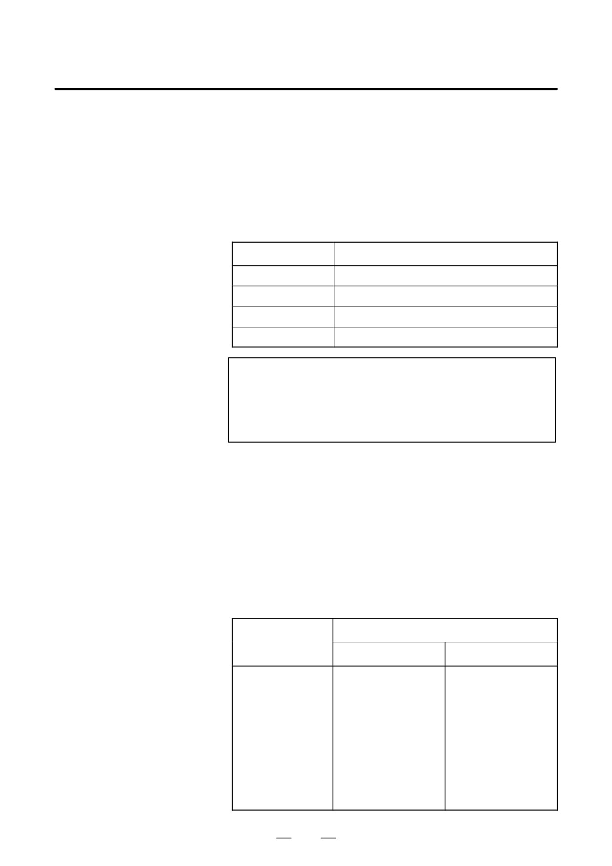
D Disabling editing of
Editing of subprograms O00008000 to O00008999, O00009000 to
programs
O00009999, O80000000 to O89999999, and O90000000 to O99999999
can be disabled.
Parameter
Program numbers for which editing is disabled
NE8(No.3202#0)
O00008000 to O00008999
NE9(No.3202#4)
O00009000 to O00009999
PRG8E(No.3204#3)
O80000000 to O89999999
PRG9E(No.3204#4)
O90000000 to O99999999
NOTE
When a wrong password has been specified for the
password function (see III-9.9), the settings of NE9 (bit 3 of
parameter No. 3202) and PRG9E (bit 4 of parameter No.
3204) cannot be changed.
D File name
For program punch by specifying a range, files are named as follows:
When punching by specifying O00000001 and O00123456:
“O00000001-G”
When punching by specifying O12345678 and O45678900:
“O12345678-G”
When 2-path control is being applied, the file name for the first path is
suffixed with “-1” and that for the second path is suffixed with “-2.”
D Special programs
Special subprogram numbers can be changed by using bit 5 (SPR) of
parameter No. 3204.
1) Macro call using G code
Program number
Parameter used to
specify G code
When SPR = 0
When SPR = 1
No.6050
O00009010
O90009010
No.6051
O00009011
O90009011
No.6052
O00009012
O90009012
No.6053
O00009013
O90009013
No.6054
O00009014
O90009014
No.6055
O00009015
O90009015
No.6056
O00009016
O90009016
No.6057
O00009017
O90009017
No.6058
O00009018
O90009018
No.6059
O00009019
O90009019
182
B-63534EN/02
PROGRAMMING
12. PROGRAM CONFIGURATION
2) Macro call using M code
Program number
Parameter used to
specify M code
When SPR = 0
When SPR = 1
No.6080
O00009020
O90009020
No.6081
O00009021
O90009021
No.6082
O00009022
O90009022
No.6083
O00009023
O90009023
No.6084
O00009024
O90009024
No.6085
O00009025
O90009025
No.6086
O00009026
O90009026
No.6087
O00009027
O90009027
No.6088
O00009028
O90009028
No.6089
O00009029
O90009029
3) Subprogram call using M code
Program number
Parameter used to
specify M code
When SPR = 0
When SPR = 1
No.6071
O00009001
O90009001
No.6072
O00009002
O90009002
No.6073
O00009003
O90009003
No.6074
O00009004
O90009004
No.6075
O00009005
O90009005
No.6076
O00009006
O90009006
No.6077
O00009007
O90009007
No.6078
O00009008
O90009008
No.6079
O00009009
O90009009
4) Macro call using T code
Program number
Parameter used to
specify T code
When SPR = 0
When SPR = 1
TCS(No.6001#5)
O00009000
O90009000
5) Macro call using ASCII code
Program number
Parameter used to
specify ASCII code
When SPR = 0
When SPR = 1
No.6090
O00009004
O90009004
No.6091
O00009005
O90009005
183

12. PROGRAM CONFIGURATION
PROGRAMMING
B-63534EN/02
6) Pattern data function
Program numaber
When SPR = 0
When SPR = 1
O00009500
O90009500
O00009501
O90009501
O00009502
O90009502
O00009503
O90009503
O00009504
O90009504
O00009505
O90009505
O00009506
O90009506
O00009507
O90009507
O00009508
O90009508
O00009509
O90009509
O00009510
O90009510
D External program
External input signals can be used to search for a program number. A
number search
program stored in CNC memory can be selected by externally inputting
a program number, between 1 and 99999999, to the CNC. For details,
refer to the appropriate manual supplied from the machine tool builder.
Limitations
D Subprogram call
This function disables subprogram call unless FS15 tape format (see
II-18) is used. This restriction also applies to calling a program in
external I/O devices (M198).
(Example)
M98 P12345678 ;
Subprogram number only. The repetition
count is not included.
D DNC
The eight-digit program number cannot be used in DNC1, DNC2,
Ethernet, data server, open CNC, and graphic conversation functions.
184
13. FUNCTIONS TO SIMPLIFY
B-63534EN/02
PROGRAMMING
PROGRAMMING
FUNCTIONS TO SIMPLIFY PROGRAMMING
13
General
This chapter explains the following items:
13.1
CANNED CYCLE
13.2
RIGID TAPPING
13.3
CANNED GRINDING CYCLE (FOR GRINDING MACHINE)
13.4
GRINDING WHEEL WEAR COMPENSATION BY
CONTINUOUS DRESSING (FOR GRINDING MACHINE)
13.5
AUTOMATIC GRINDING WHEEL DIAMETER
COMPENSATION AFTER DRESSING
13.6
IN-FEED GRINDING ALONG THE Y AND Z AXES AT THE END
OF TABLE SWING (FOR GRINDING MACHINE)
13.7
OPTIONAL ANGLE CHAMFERING AND CORNER ROUNDING
13.8
EXTERNAL MOTION FUNCTION
13.9
FIGURE COPY (G72.1, G72.2)
13.10
THREE-DIMENSIONAL COORDINATE CONVERSION
(G68, G69)
13.11
INDEX TABLE INDEXING FUNCTION
185

13. FUNCTIONS TO SIMPLIFY
PROGRAMMING
PROGRAMMING
B-63534EN/02
Canned cycles make it easier for the programmer to create programs.
13.1
With a canned cycle, a frequently-used machining operation can be
CANNED CYCLE
specified in a single block with a G function; without canned cycles,
normally more than one block is required. In addition, the use of canned
cycles can shorten the program to save memory.
Table 13.1 (a) lists canned cycles.
Table 13.1 (a) Canned cycles
Operation at the
G code
Drilling(-Z direction)
Retraction(+Z direction)
Application
bottom of a hole
G73
Intermittent feed
-
Rapid traverse
High-speed peck drilling
cycle
G74
Feed
Dwell→Spindle CW
Feed
Left-hand tapping cycle
G76
Feed
Oriented spindle
Rapid traverse
Fine boring cycle
stop
G80
-
-
-
Cancel
G81
Feed
-
Rapid traverse
Drilling cycle, spot drilling
cycle
G82
Feed
Dwell
Rapid traverse
Drilling cycle, counter boring
cycle
G83
Intermittent feed
-
Rapid traverse
Peck drilling cycle
G84
Feed
Dwell→Spindle
Feed
Tapping cycle
CCW
G85
Feed
-
Feed
Boring cycle
G86
Feed
Spindle stop
Rapid traverse
Boring cycle
G87
Feed
Spindle CW
Rapid traverse
Back boring cycle
G88
Feed
Dwell→spindle stop
Manual
Boring cycle
G89
Feed
Dwell
Feed
Boring cycle
186
13. FUNCTIONS TO SIMPLIFY
B-63534EN/02
PROGRAMMING
PROGRAMMING
Explanations
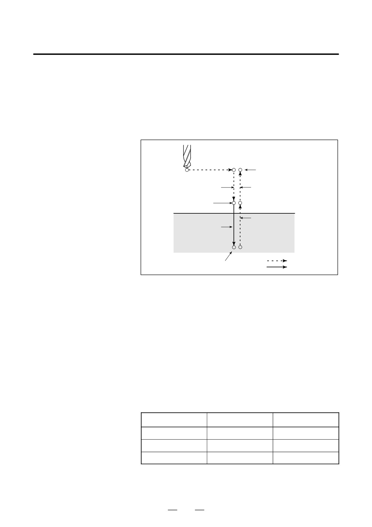
A canned cycle consists of a sequence of six operations (Fig. 13.1 (a))
Operation 1 Positioning of axes X and Y
(including also another axis)
Operation 2 Rapid traverse up to point R level
Operation 3 Hole machining
Operation 4 Operation at the bottom of a hole
Operation 5
Retraction to point R level
Operation 6
Rapid traverse up to the initial point
Operation 1
Initial level
Operation 2
Operation 6
Point R level
Operation 5
Operation 3
Rapid traverse
Operation 4
Feed
Fig. 13.1 Canned cycle operation sequence
D Positioning plane
The positioning plane is determined by plane selection code G17, G18,
or G19.
The positioning axis is an axis other than the drilling axis.
D Drilling axis
Although canned cycles include tapping and boring cycles as well as
drilling cycles, in this chapter, only the term drilling will be used to refer
to operations implemented with canned cycles.
The drilling axis is a basic axis (X, Y, or Z) not used to define the
positioning plane, or any axis parallel to that basic axis.
The axis (basic axis or parallel axis) used as the drilling axis is determined
according to the axis address for the drilling axis specified in the same
block as G codes G73 to G89.
If no axis address is specified for the drilling axis, the basic axis is
assumed to be the drilling axis.
Table 13.1 (b) Positioning plane and drilling axis
G code
Positioning plane
Drilling axis
G17
Xp-Yp plane
Zp
G18
Zp-Xp plane
Yp
G19
Yp-Zp plane
Xp
Xp : X axis or an axis parallel to the X axis
Yp : Y axis or an axis parallel to the Y axis
Zp : Z axis or an axis parallel to the Z axis
187
13. FUNCTIONS TO SIMPLIFY
PROGRAMMING
PROGRAMMING
B-63534EN/02
Examples
Assume that the U, V and W axes be parallel to the X, Y, and Z axes
respectively. This condition is specified by parameter No. 1022.
G17 G81 ………Z _ _ : The Z axis is used for drilling.
G17 G81 ………W _ _ : The W axis is used for drilling.
G18 G81 ………Y _ _ : The Y axis is used for drilling.
G18 G81 ………V _ _ : The V axis is used for drilling.
G19 G81 ………X _ _ : The X axis is used for drilling.
G19 G81 ………U _ _ : The U axis is used for drilling.
G17 to G19 may be specified in a block in which any of G73 to G89 is
not specified.
WARNING
Switch the drilling axis after canceling a canned cycle.
NOTE
A parameter FXY (No. 6200 #0) can be set to the Z axis
always used as the drilling axis. When FXY=0, the Z axis
is always the drilling axis.
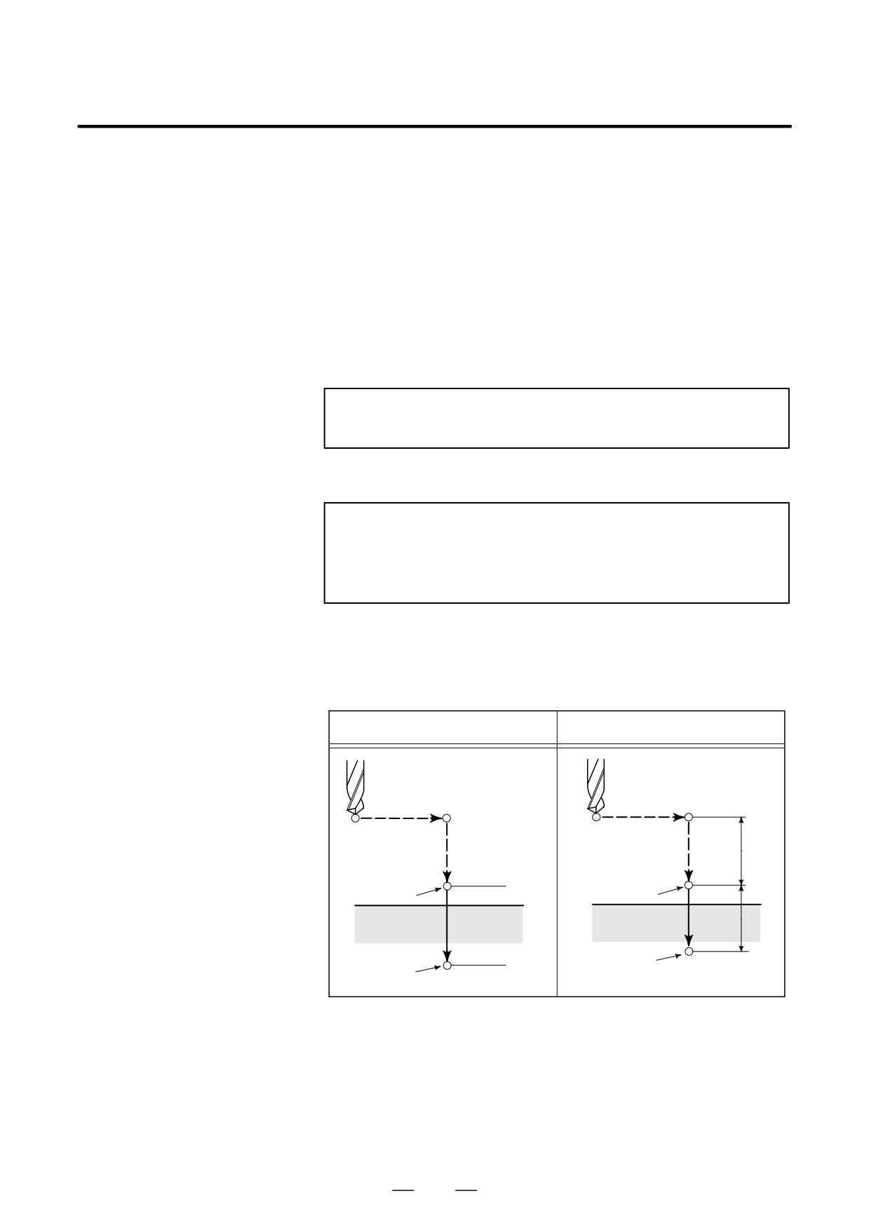
D Travel distance along the
The travel distance along the drilling axis varies for G90 and G91 as
drilling axis G90/G91
follows:
G90 (Absolute Command)
G91 (Incremental Command)
R
R
Point R
Point R
Z=0
Z
Point Z
Z
Point Z
D Drilling mode
G73, G74, G76, and G81 to G89 are modal G codes and remain in effect
until canceled. When in effect, the current state is the drilling mode.
Once drilling data is specified in the drilling mode, the data is retained
until modified or canceled.
Specify all necessary drilling data at the beginning of canned cycles; when
canned cycles are being performed, specify data modifications only.
188
13. FUNCTIONS TO SIMPLIFY
B-63534EN/02
PROGRAMMING
PROGRAMMING
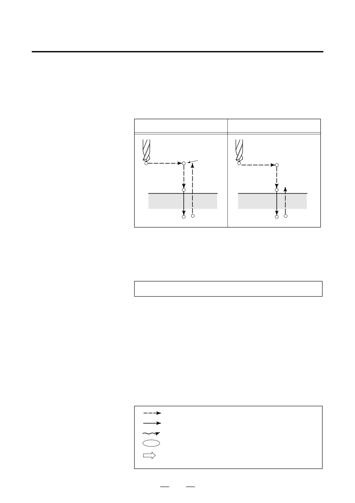
D Return point level
When the tool reaches the bottom of a hole, the tool may be returned to
G98/G99
point R or to the initial level. These operations are specified with G98 and
G99. The following illustrates how the tool moves when G98 or G99 is
specified. Generally, G99 is used for the first drilling operation and G98
is used for the last drilling operation.
The initial level does not change even when drilling is performed in the
G99 mode.
G98(Return to initial level )
G99(Return to point R level)
Initial level
Point R level
D Repeat
To repeat drilling for equally-spaced holes, specify the number of repeats
in K_.
K is effective only within the block where it is specified.
Specify the first hole position in incremental mode (G91).
If it is specified in absolute mode (G90), drilling is repeated at the same
position.
Number of repeats K The maximum command value = 9999
If K0 is specified, drilling data is stored, but drilling is not performed.
D Cancel
To cancel a canned cycle, use G80 or a group 01 G code.
Group 01 G codes
G00 : Positioning (rapid traverse)
G01 : Linear interpolation
G02 : Circular interpolation or helical interpolation (CW)
G03 : Circular interpolation or helical interpolation (CCW)
G60 : Single direction positioning (when the MDL bit (bit 0 of
parameter 5431) is set to 1)
D Symbols in figures
Subsequent sections explain the individual canned cycles. Figures in
these explanations use the following symbols:
Positioning (rapid traverse G00)
Cutting feed (linear interpolation G01)
Manual feed
OSS Oriented spindle stop
(The spindle stops at a fixed rotation position)
Shift (rapid traverse G00)
P
Dwell
189