FANUC Series 30i/300i/300is-MODEL A. Machining Center System. User's manual - page 252
 

  Index      Manuals     FANUC Series 30i/300i/300is-MODEL A. Machining Center System. User's manual (B-63944EN/03)


Search            copyright infringement  


Content      ..     250      251      252      253     ..


FANUC Series 30i/300i/300is-MODEL A. Machining Center System. User's manual - page 252


1.ROUTINE MAINTENANCE

 MAINTENANCE 

B-63944EN/03


- 1972 - 

 CAUTION 


Complete steps <1> to <3> within 30 minutes. 


If the battery is left removed for a long time, the 
memory would lose the contents. 


If there is a danger that the replacement cannot be 
completed within 30 minutes, save the whole 
contents of the SRAM to a memory card.    The 
contents of the memory can be easily restored with 
the memory card in case the memory loses the 
contents. 

 
Discard the dead battery, observing appropriate municipal rules and 
regulations.    When discarding the battery, insulate the terminal with 
a tape so that no short-circuit would occur. 
 

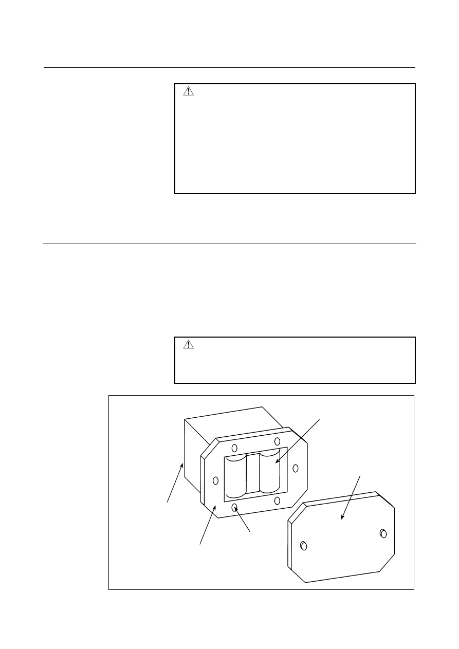
When using commercial D-size alkaline dry cells 
  - Replacing the battery 

<1>  Have commercial D-size alkaline dry cells handy. 
<2>  Turn the CNC on. 
<3>  Remove the cover from the battery case. 
<4>  Replace the old dry cells with new ones.    Mount the dry cells in 

a correct orientation. 

<5>  Replace the cover on the battery case. 
 

 CAUTION 


In the power-off state, the battery should be 
replaced as in the case of the lithium battery, which 
is descried above. 


Connection terminal on the back

Case

4 mounting holes

2 dry cells

Cover


B-63944EN/03

 MAINTENANCE 

1.ROUTINE MAINTENANCE


- 1973 - 

1.3.3 

Battery in the PANEL 

i

 (3 VDC) 

 
A lithium battery is used to back up BIOS data in the PANEL 

i

.  This 

battery is factory-set in the PANEL 

i

.  This battery has sufficient 

capacity to retain BIOS data for one year. 
When the battery voltage becomes low, the following message 
appears on the self test screen displayed at turn-on, and the self test 
pauses. 

CMOS Battery Failure 

If this message appears, replace the battery as soon as possible (within 
one week).    FANUC recommends that the battery be replaced once 
per year regardless of whether a battery alarm is issued. 
 

  - Replacing the battery 

(1)  To guard against the possible loss or destruction of BIOS 

parameters, write down the BIOS parameter values. 

(2)  Obtain a new lithium battery (A02B-0200-K102). 
(3)  After power has been supplied for at least five seconds, turn off 

the power to PANEL 

i

.  Remove the intelligent terminal from 

the panel so that replacement work can be done from the rear of 
the intelligent terminal. 

(4)  Detach the connector of the lithium battery, and remove the 

battery from the battery holder. 

(5)  Attach the connector, and place the battery in the battery holder. 
(6) Install 

PANEL 

i

 again. 

(7)  Turn on the power, and check that the BIOS parameters are 

maintained (BIOS setup is not activated forcibly). 

 
Between removing an old battery and inserting new battery, no more 
than five minutes must be allowed to elapse. 


1.ROUTINE MAINTENANCE

 MAINTENANCE 

B-63944EN/03


- 1974 - 

Connector

(BAT1)

Lithium battery

A02B-0200-K102


Fig. 1.3.3 (a)    Lithium battery connection for PANEL 

i


B-63944EN/03

 MAINTENANCE 

1.ROUTINE MAINTENANCE


- 1975 - 

1.3.4 

Battery for Absolute Pulsecoders 

 
(1)  When the absolute pulsecoder battery voltage falls, "APC" blinks 

in the status display on the screen. When the battery voltage 
further falls, alarms DS0306 to 0308 are issued. 

(2)  When alarm DS0307 (alarm indicating the voltage of the battery 

becomes low) occurs, replace the battery as soon as possible.    In 
general, the battery should be replaced within one or two weeks, 
however, this depends on the number of Pulsecoders used. 

(3)  If the voltage of the battery becomes any lower, alarm DS0306 

(battery zero alarm) occurs.  In this case, the current positions 
for the Pulsecoders can no longer be maintained. 


In this state, alarm DS0300 (reference position return request 
alarm) occurs.    After replacing the batteries, be sure to perform 
manual reference position return. 

(4)  The service life of the batteries is about two years if they are 

used in a six-axis configuration with 

α

i

/

β

i

 series servo motors 

and one year if they are used in a six-axis configuration with 

α

/

β


series servo motors.    FANUC recommends that you replace the 
batteries periodically according to the battery service life. 

(5)  To connect the battery, use the battery case or incorporate the 

battery into the servo amplifier.  Note that the attachment 
method of the battery depends on the connection method and the 
type of servo amplifier. 


 - Replacing batteries 

To prevent absolute position information in absolute Pulsecoders from 
being lost, turn on the machine power before replacing the battery.  
The replacement procedure is described below.  (Note:  The 
turning-on step is not required when the 

α

i

 series servo motor or 

β

i


series servo motor (

β

i

S 0.4 to 

β

i

S 22) is used.) 

 
(1)  Turn the servo unit (machine) on. 
(2)  Place the machine in the emergency stop state. 
(3)  Confirm that servo motors are not active. 
(4)  Make sure the DC link charge LED is off. 
(5)  Remove the old battery and then attach a new one. 
(6)  Now, replacement has been completed.    The system power can 

be turned off. 


1.ROUTINE MAINTENANCE

 MAINTENANCE 

B-63944EN/03


- 1976 - 

NOTE 


The absolute Pulsecoder of the servo motor 

α

i

/

α

i

series or 

β

i

S (

β

i

S 0.4 to 

β

i

S 22) series is 

incorporated with a backup capacitor as standard. 
This backup capacitor enables an absolute position 
detection to be continued for about 10 minutes. 
Therefore, no manual reference position return 
need be performed if the time during which servo 
amplifier power is kept off for battery replacement 
is within 10 minutes. If battery replacement takes 
10 minutes or more, the power must remain turned 
on. 


 WARNING 

1  When replacing the battery, be careful not to touch 

bare metal parts in the panel.    In particular, be 
careful not to touch any high-voltage circuits due to 
the electric shock hazard. 

2  Before replacing the battery, make sure the DC link 

charge LED is off.    Otherwise, an electric shock 
may be received. 

3  Be sure to use the specified battery.    If another 

type of battery is used, it may overheat, blow out, 
or catch fire. 

4  Install the battery with correct polarity.    If the 

battery is installed with incorrect polarity, it may 
overheat, blow out, or catch fire. Or, absolute 
position information in absolute Pulsecoders may 
be lost. 

5  During attachment of the battery, insert the 

factory-attached protection socket into the CX5X or 
CX5Y connector, whichever is not used.    If the +6 
V pin and 0 V pin are short-circuited, the battery 
may overheat, blow out, or catch fire.    Or, 
absolute position information in absolute 
Pulsecoders may be lost. 


B-63944EN/03

 MAINTENANCE 

1.ROUTINE MAINTENANCE


- 1977 - 

  - Replacing D-size alkaline dry cells in the battery case 

Replace four D-size alkaline batteries (A06B-6050-K061) in the 
battery case installed in the machine. 
(1)  Have four D-size alkaline batteries on hand. 
(2)  Loosen the screws on the battery case. Remove the cover. 
(3)  Replace the alkaline batteries in the case. Pay careful attention to 

the polarity of the alkaline batteries. 

(4)  Attach the cover. 
 

Screws

Cover


 WARNING 


Install the battery with correct polarity.    If the 
battery is installed with incorrect polarity, it may 
overheat, blow out, or catch fire.    Or, absolute 
position information in absolute Pulsecoders may 
be lost. 


1.ROUTINE MAINTENANCE

 MAINTENANCE 

B-63944EN/03


- 1978 - 

  - Attaching the built-in battery (

α

i

 series servo amplifier) 

Attach the lithium battery (A06B-6073-K001) to the servo amplifier. 
 
[Attachment procedure] 
(1)  Remove a battery cover from the servo amplifier. 
(2)  Attach the battery as shown below. 
(3)  Re-attach the cover. 
(4)  Connect the connector of battery with CX5X of the servo 

amplifier. 


SVM

CX5X, CX5Y

+6V

0V

Battery

Battery cover

Connector

Inserting way

Cable side

Red: +6V

Black: 0V


 CAUTION 


Attaching the battery from the cable outlet applies 
tension to the cable.    Therefore, attach the cable 
from another place to prevent the cable from being 
stretched.    If this cable is connected on a stretch 
condition, a bad conductivity may be occurred. 


B-63944EN/03

 MAINTENANCE 

1.ROUTINE MAINTENANCE


- 1979 - 

  - Attaching the built-in battery (

β

 series servo amplifier) 

Attach the lithium battery (A06B-6093-K001) to the servo amplifier. 
 
[Attachment procedure] 
(1)  In case of SVU-12 or SVU-20, remove the battery cover under 

the servo amplifier grasping its left and right sides. In case of 
SVU-40 or SVU-80, remove the cover attached on right side of 
the servo amplifier grasping its upper and lower sides. 

(2)  Remove the connector of battery.    (Connector CX5X or CX5Y) 
(3)  Replace the battery and connect the connector. 
(4)  Mount the battery cover. 
 

Battery

Battery cover

SVU-12, SVU-20


Battery

Battery cover

Pass the battery cable to this slit.

SVU-40, SVU-80


Content      ..     250      251      252      253     ..