FANUC Series 30i/300i/300is-MODEL A. Machining Center System. User's manual - page 251
 

  Index      Manuals     FANUC Series 30i/300i/300is-MODEL A. Machining Center System. User's manual (B-63944EN/03)


Search            copyright infringement  


Content      ..     249      250      251      252     ..


FANUC Series 30i/300i/300is-MODEL A. Machining Center System. User's manual - page 251


1.ROUTINE MAINTENANCE

 MAINTENANCE 

B-63944EN/03


- 1964 - 

1.1 

ACTION TO BE TAKEN WHEN A PROBLEM OCCURRED 

 
If an unexpected operation occurs or an alarm or warning is output 
when the CNC and machine are used, the problem needs to be solved 
quickly.  For this purpose, the status of the problem must be 
identified correctly, and a proper action must be taken. 
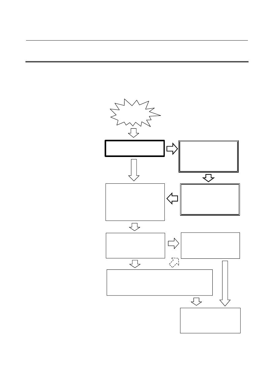
The procedure for taking an action for a problem is shown below. 

Problem!

Dangerous?

Danger to you and others

Not dangerous

Check and identify problem.
- Warning
- Alarm
- Abnormal operation

- Wrong operation, etc.

Dangerous

Take action to avoid danger.

- Stop machine immediately.

- Refuge to safe place immediately.

Check status and how problem
occurred.
- Time and place of problem

occurrence

- Operation procedure

Confirm and secure safety.

- Confirm current safety.

- Check machine and circumstances.

- Turn off power to machine.

Investigate cause and take action.

- Check and correct machining program and set data items.
- Review and modify operation procedure.
- Check and repair machine operation sections.

Recovery work

- Action by you or machine tool builder

- Check operation after recovery.

If recovery is impossible,

immediately notify sales agent or

supplier of problem details for

action.


For details of investigation and action on problems arising from the 
CNC, refer to "TROUBLESHOOTING PROCEDURE" in the 
Maintenance Manual (B-63945EN) issued by FANUC. 

B-63944EN/03

 MAINTENANCE 

1.ROUTINE MAINTENANCE


- 1965 - 

1.2 

BACKING UP VARIOUS DATA ITEMS 

 
With the CNC, various data items such as offset data and system 
parameters are stored in the SRAM of the control unit and are 
protected by a backup battery.    However, an accident can erase the 
data.    By storing the data at another location (outside the CNC), the 
data, when lost, can be restored. 
So, when the machine is started up or data is updated, for example, the 
data should be backed up (stored outside the CNC). 
 

  - Data backup operation 

The data items listed below should be backed up.    For the method of 
data output operation, see the chapter of "DATA INPUT/OUTPUT" in 
this manual. 


<1> System parameters 

 See 

III-8.1.2. 

<2> Machining programs 

 See 

III-8.1.1. 

<3>  Tool offset data 

 See 

III-8.1.3. 

<4> PMC data 

  See PMC PROGRAMMING MANUAL (B-63983EN). 

<5> 

Pitch error compensation data (when the pitch error 
compensation function is selected.) 

 See 

III-8.1.4. 

<6> 

Three-dimensional error compensation (when the 
three-dimensional error compensation function is selected.) 

 See 

III-8.1.5. 

<7> Custom macro variables (when the custom macro function is 

selected.) 

 See 

III-8.1.6. 

<8> Workpiece coordinate system setting data (when the workpiece 

coordinate system function is selected.) 

 See 

III-8.1.7. 

<9> Tool management data (when the tool management function is 

selected.) 

 See 

III-8.1.9. 

 
It is recommended that recording media (such as floppy disks and 
memory cards) daily used with the machine be used to store data.  
Stored data should be managed properly so that the data can be 
restored quickly if a problem occurs. 


1.ROUTINE MAINTENANCE

 MAINTENANCE 

B-63944EN/03


- 1966 - 

  - Data restoration work 

In order to restore lost data to the state of the stored data, input the 
data backed up according to the previous item into the CNC.    For the 
method of data input operation, see the chapter of "DATA 
INPUT/OUTPUT" in this manual. 
 

 WARNING 


After inputting stored data, do not start an 
operation immediately.    Instead, check that the 
data is input correctly and that settings are made to 
meet a desired operation. 
If an operation is executed without making this 
check, the machine and workpiece can be 
damaged and personal injury can occur due to an 
unexpected machine movement.    Use sufficient 
care. 


 CAUTION 


Before recovery of the following data items, consult 
with the machine tool builder of the machine used: 

 System parameters 

 PMC data 

 Macro programs and custom macro variables 

 Pitch error compensation values 


NOTE 


The method of recovery described in this section is 
intended just to restore the state of the backed up 
data, and does not guarantee recovery of the state 
that was present when the data was lost. 


B-63944EN/03

 MAINTENANCE 

1.ROUTINE MAINTENANCE


- 1967 - 

1.3 

METHOD OF REPLACING BATTERY 

 
This chapter describes how to replace the CNC backup battery and 
absolute Pulsecoder battery.  This section consists of the following 
subsections:: 
1.3.1  Replacing Battery for LCD-mounted Type CNC Control   

Unit .......................................................................................1968 

1.3.2  Replacing the Battery for Stand-alone Type CNC Control   

Unit .......................................................................................1971 

1.3.3  Battery in the PANEL 

i

 (3 VDC) .........................................1973 

1.3.4  Battery for Absolute Pulse coders ........................................1975 
 

Battery for memory backup 

Offset data, and system parameters are stored in SRAM in the control 
unit.  The power to the SRAM is backed up by a lithium battery 
mounted on the front panel of the control unit.    Therefore, the above 
data is not lost even if the main battery fails.    The backup battery is 
installed in the control unit prior to being shipped from the factory.  
This battery can provide backup for the memory contents for about a 
year. 
When the battery voltage falls, alarm message "BAT" blinks on the 
LCD display and the battery alarm signal is output to the PMC.  
When this alarm is displayed, replace the battery as soon as possible.   
In general, the battery can be replaced within one or two weeks of the 
alarm first being issued.  This, however, depends on the system 
configuration. 
If the battery voltage subsequently drops further, backup of memory 
can no longer be provided.    Turning on the power to the control unit 
in this state causes system alarm to be issued because the contents of 
memory are lost.    Replace the battery, clear the entire memory, then 
reenter the data. 
Replace the memory backup battery while the control unit is brought 
off. 
The following two kinds of batteries can be used. 

  Lithium battery, incorporated into the CNC control unit. 

  Two alkaline dry cells (size D) in an external battery case. 


NOTE 


A lithium battery is installed as standard at the 
factory. 


1.ROUTINE MAINTENANCE

 MAINTENANCE 

B-63944EN/03


- 1968 - 

1.3.1 

Replacing Battery for LCD-mounted Type CNC Control Unit 


When using a lithium battery 
 - Replacement procedure 

When a lithium battery is used 
Prepare a new lithium battery (ordering code: A02B-0200-K102 
(FANUC specification: A98L-0031-0012)). 
<1>  Turn on the power to the CNC.    After about 30 seconds, turn off 

the power. 

<2>  Remove the old battery from the back of the CNC control unit. 
 

First, unplug the connector by yanking the battery cable, then 
take the battery out of its case. 


The battery case of a control unit without option slots is located 
at the back of the unit as shown in the figure below. The battery 
case of a control unit with option slots is located next to the fan 
on the top of the unit. 

<3>  Insert a new battery and reconnect the connector. 
<4>  Clamp the battery cable as shown in Fig. 1.3.1 (c). 
 

Lithium battery

A02B-0236-K102

Connector

Battery case


Fig. 1.3.1 (a)    Unit without option slots 


B-63944EN/03

 MAINTENANCE 

1.ROUTINE MAINTENANCE


- 1969 - 

Battery case

Connector

Lithium battery

A02B-0236-K102


Fig. 1.3.1 (b)    Unit with option slots 


Battery cable


Fig. 1.3.1 (c)    Clamping the battery cable 


 WARNING 


Using other than the recommended battery may 
result in the battery exploding.    Replace the 
battery only with the specified battery 
(A02B-0200-K102). 


 CAUTION 


Steps <1> to <3> should be completed within 30 
minutes. 


Do not leave the control unit without a battery for 
any longer than the specified period.  Otherwise, 
the contents of memory may be lost. 


If steps <1> to <3> may not be completed within 30 
minutes, save all contents of the SRAM to the 
memory card beforehand.    Thus, if the contents of 
the SRAM are lost, the contents can be restored 
easily. 


For the method of operation, refer to Maintenance 
Manual. 

 
When discarding a battery, observe the applicable ordinances or other 
rules of your local government.  Also, cover the terminals of the 
battery with vinyl tape or the like to prevent a short-circuit. 

1.ROUTINE MAINTENANCE

 MAINTENANCE 

B-63944EN/03


- 1970 - 


When using commercial alkaline dry cells (size D) 
 - Replacement procedure 

<1>  Prepare two alkaline dry cells (size D) commercially available. 
<2>  Turn on the power to the control unit. 
<3>  Remove the battery case cover. 
<4>  Replace the cells, paying careful attention to their orientation. 
<5>  Reinstall the cover onto the battery case. 
 

 CAUTION 


When replacing the alkaline dry cells while the 
power is off, use the same procedure as that for 
lithium battery replacement described above. 


Cover

Alkaline dry cell


×


2

Connection terminal on the rear

Battery case

Mounting hole 

×

 4


B-63944EN/03

 MAINTENANCE 

1.ROUTINE MAINTENANCE


- 1971 - 

1.3.2 

Replacing the Battery for Stand-alone Type CNC Control Unit 


When using a lithium battery 
  - Replacing the battery 

If a lithium battery is used, have A02B-0200-K102 (FANUC internal 
code:  A98L-0031-0012) handy. 
<1>  Turn the CNC on.    About 30 seconds later, turn the CNC off. 
<2>  Remove the battery from the top area of the CNC unit. 
 

First, unplug the connector by yanking the battery cable, then 
take the battery out of the case. 


The battery case is provided in the top area of the face plate of 
the main board. 

<3>  Replace the battery, then connect the connector. 
 

Battery case

Lithium battery
A02B-0200-K102

Connector


 WARNING 


The incorrect mounting of the battery may cause 
an explosion.    Avoid using any battery other than 
the one specified here (A02B-0200-K102). 


Content      ..     249      250      251      252     ..