FANUC Series 30i/300i/300is-MODEL A. Machining Center System. User's manual - page 243
13
.
GRAPHIC
FUNCTION
OPERATION
B-63944EN/03
- 1900 -
13.1
GRAPHIC DISPLAY
The graphic display functions enable drawing of the tool path of the
program currently used for machining.
These functions are intended to display the movement of the tool
during automatic operation or during manual operation.
This enables the operator to check the progress of machining and the
current tool position.
These functions include the following:
•
The current tool position in the workpiece coordinate system is
displayed.
•
Graphic coordinates can be set freely.
•
Rapid traverse and cutting feed can be drawn using a different
color for each.
•
The values of F, S, and T in the program during drawing are
displayed.
•
Graphic enlargement or reduction is possible.
Graphic display procedure
Explanation
Press the function key
then press the [GRAPH] soft key to
display the tool path graphic screen.
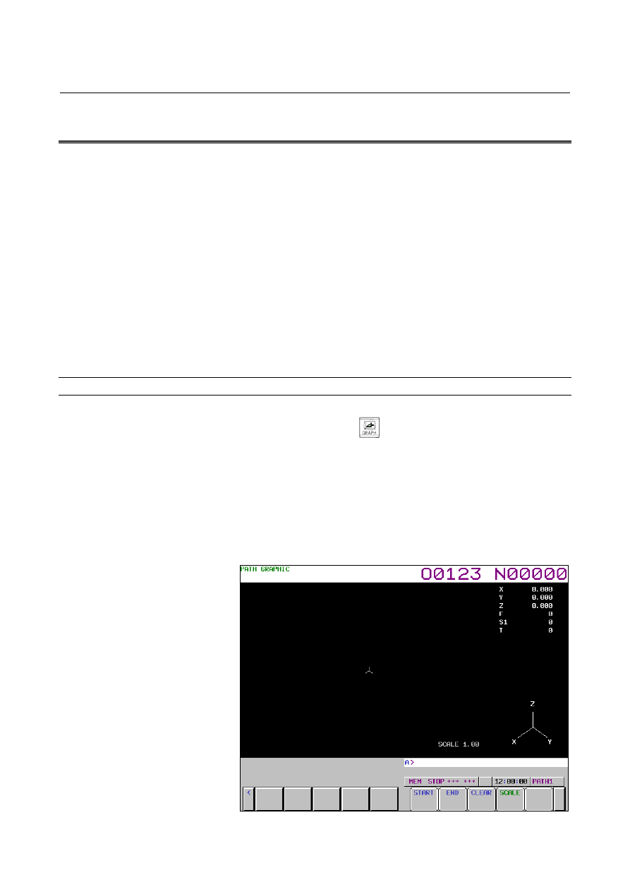
- Tool path graphic screen
The tool path graphic screen consists of three major areas:
•
Graphic area for drawing a tool path
•
Area for displaying machining information such as tool position
information
•
Area for displaying a graphic coordinate system
Fig. 13.1 (a) Tool path graphic screen (M series)