FANUC Series 30i/300i/300is-MODEL A. Machining Center System. User's manual - page 244
 

  Index      Manuals     FANUC Series 30i/300i/300is-MODEL A. Machining Center System. User's manual (B-63944EN/03)


Search            copyright infringement  


Content      ..     242      243      244      245     ..


FANUC Series 30i/300i/300is-MODEL A. Machining Center System. User's manual - page 244


13

.

GRAPHIC

 FUNCTION

 OPERATION 

B-63944EN/03


- 1908 - 


Y


X

Z

X'

Z'

Vertical rotation axis 
rotation plane


Initial vertical
rotation axis

Vertical rotation 
plane


20

°

65

°

Y'


Vertical rotation 
axis


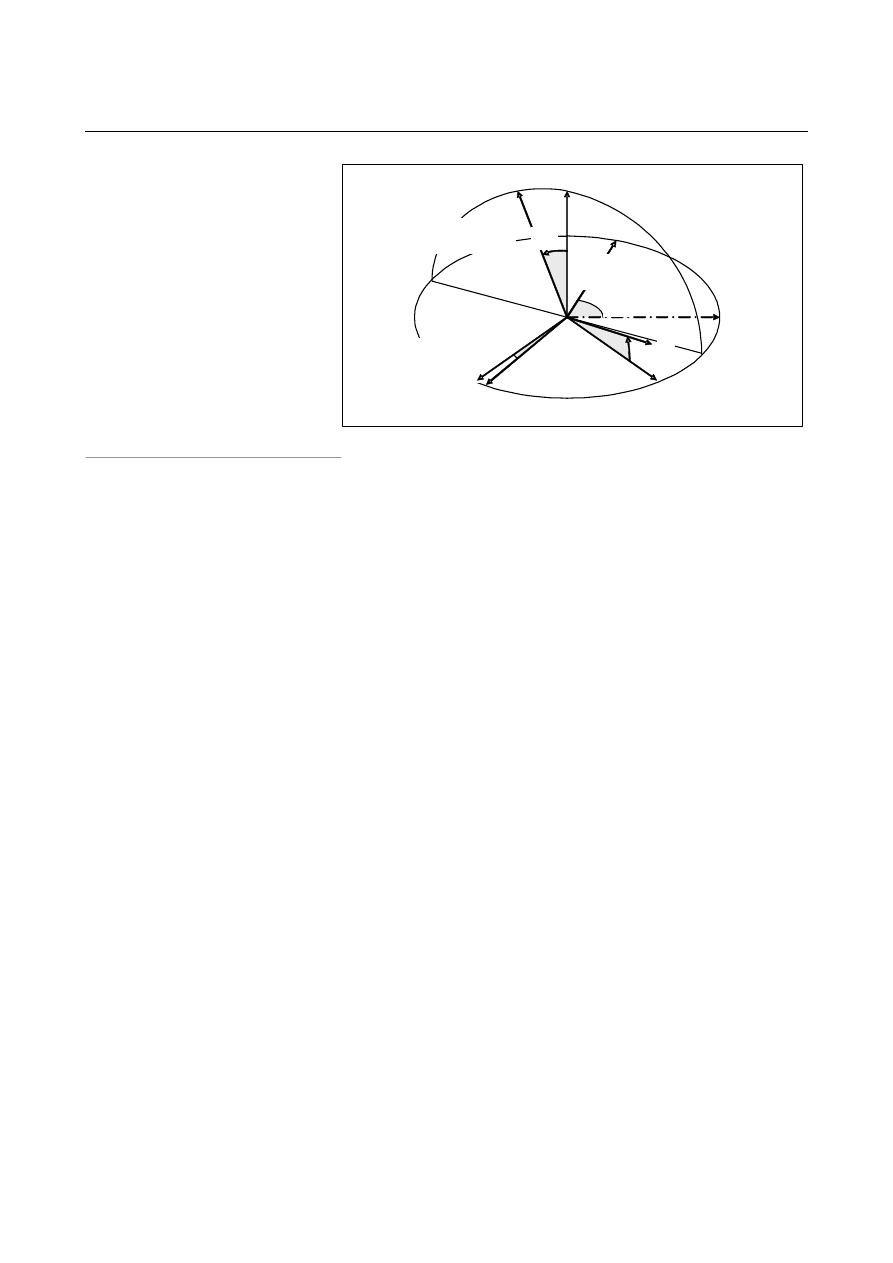
Fig. 13.1 (l)    Coordinate system rotation in vertical direction 


 - Graphic color 

Set a graphic color number for a tool path for each of cutting feed and 
rapid traverse. 


1: Red  2: Green  3: Yellow  4: Blue 


5: Purple  6: Sky blue  7: White 


  - Graphic range setting 

Set a graphic range so that a tool path can be drawn in the tool path 
graphic area.    Two methods are available: 
1.  Method that sets graphic center coordinates and a scale 
2.  Method that sets the maximum values and minimum values of a 

graphic range 

Whether method 1 or method 2 is used is determined by which 
parameters were set most recently.    A set graphic range is preserved 
even if the power is turned off. 
 

      1. Method that sets graphic center coordinates and a scale 

Set the coordinates of the center of a tool path graphic area in the 
workpiece coordinate system.    Then, set a scale used to contain the 
graphic range in the tool path graphic area. 
Set a scale value from 0.01 to 100 (magnification). 
As a smaller scale is set, a tool path can be drawn in a wider range.   
As a larger scale is set, a tool path is drawn by enlarging the tool path 
around the graphic center coordinates. 
 

      2. Method that sets the maximum values and minimum values of a graphic range 

Set the maximum coordinates and minimum coordinates of a desired 
graphic range in the workpiece coordinate system.  Drawing is 
performed so that the specified entire range is contained in the tool 
path graphic area. 
 
From set maximum values and minimum values, graphic center 
coordinates and a sale are automatically calculated to update the 
graphic center coordinates and scale on the graphic parameter screen. 

B-63944EN/03

 OPERATION 

13.GRAPHIC FUNCTION


- 1909 - 

When a scale is automatically determined, the scale is clamped to 
within the range 0.01 to 100.    Moreover, a maximum value must be 
greater than the corresponding minimum value. 
 

NOTE 

      When the maximum values and minimum values of 

a graphic range are set, the graphic center 
coordinates and scale are automatically updated.   
However, when the graphic center coordinates and 
scale are changed, the maximum values and 
minimum values of the graphic range are not 
automatically updated. 


 - Automatic erasure 

Before drawing is started, the previous drawing can be erased 
automatically. 
1:  Immediately before drawing is started, the previous drawing is 

erased automatically. 

0:    The previous drawing is not erased automatically. 
 

  - Graphic axis number 

Set which controlled axis to be assigned to which graphic axis. 
For each controlled axis, set one of the following graphic axis 
numbers: 
 

First graphic axis: 


Second graphic axis: 


Third graphic axis: 


Axis not used for drawing:  0 


NOTE 

1  When 0 is set for all controlled axes, it is assumed 

that 1, 2, and 3 are set sequentially for the first to 
the third controlled axes. 

2  With the T series, a tool path is drawn along the 

first and second graphic axes.    No tool path is 
drawn along the third graphic axis. 


13

.

GRAPHIC

 FUNCTION

 OPERATION 

B-63944EN/03


- 1910 - 

Operation for graphic parameter setting 


Operation 

  - Moving the cursor 

The cursor can be moved to a desired parameter by the page key 

 or 

  and the cursor key 

, or 

With the cursor keys, however, you cannot move from page 1 or 2 to 
page 3. 
 

  - Input of settings (absolute input) 

Method 1 

(1)  Key in a value to be set. 
(2)  Press the [INPUT] soft key. 

Method 2 

(1)  Key in a value to be set. 
(2) Press 

the 

 key. 


  - Input of settings (incremental input) 

Method 1 

(1)  Key in a value to be incremented to or decremented from 

the current setting. 

(2)  Press the [+INPUT] soft key. 


Procedure for tool path drawing 


Procedure 

  - Start of drawing 

(1)  Display the tool path graphic screen. 
(2)  Press the [START] soft key. 

The state that enables the movement of the tool in automatic 
operation or manual operation to be drawn is set. 
Afterwards, tool path drawing continues even if another screen is 
displayed. 

(3)  Start automatic operation or manual operation. 
 

  - End of drawing 

(1)  Display the tool path graphic screen. 
(2)  Press the [END] soft key. 

Tool path drawing ends. 


  - Erasure of the drawing 

(1)   Press the [END] soft key to end drawing. 
(2)  Press the [CLEAR] soft key.  The tool path drawn so far is 

erased. 

B-63944EN/03

 OPERATION 

13.GRAPHIC FUNCTION


- 1911 - 

NOTE 

1  Set the machine lock state to perform drawing only 

without moving the tool. 

2  When the feedrate is high, the tool path may not be 

drawn correctly.    In such a case, decrease the 
feedrate by performing, for example, a dry run. 


Enlarged/reduced display 

On the tool path graphic screen, you can move the center position of 
the tool path drawing or enlarge the tool path drawing while viewing 
the drawn tool path. 
If any of these operations is executed, the tool path already drawn is 
cleared. 
 

  - Procedure for changing the graphic range by setting a graphic center and 

magnification 

The center position of drawing can be moved.    At the same time, the 
scale can also be changed.  So, the tool path can be enlarged or 
reduced at a desired new center position. 
 
(1)  Press the [SCALE] soft key then the [CENTER] soft key. 

A yellow cursor appears at the center of the screen, and the soft 
key display is changed. 

(2)  Move the yellow cursor to a new graphic center position by using 

the cursor key 

, or 

(3)  When changing the scale, key in a value from 0.01 to 100 

(magnification) then press the [INPUT] soft key.  An input 
value is displayed at "SCALE" in the lower-right corner of the 
screen. 

  When you press the [+INPUT] soft key, the current 

magnification is incremented by an input value. 

(4)  Press the [EXEC] soft key to end the operation. 

After this step, the setting for graphic movement is effective to 
enable drawing with the new setting. 


Before graphic movement

After graphic movement


Fig. 13.1 (m)    Graphic movement (magnification = 2.00


13

.

GRAPHIC

 FUNCTION

 OPERATION 

B-63944EN/03


- 1912 - 

  - Procedure for changing the graphic range with a rectangle 

A tool path can be drawn by enlarging a specified rectangular area. 
 
(1)  Press the [SCALE] soft key then the [RECTANGLE] soft key. 

Two cursors, one in red and the other in yellow, appear at the 
center of the screen, and the soft key display is changed. 

(2)  Move the yellow cursor by using the cursor key 

, or 

. The cursor to be moved can be switched by 

pressing the [CURSOR UP/DOWN] soft key. 
Move the two cursors to the diagonal points of a new rectangular 
graphic range.    A tool path is drawn next time so that the drawn 
tool path is contained in this rectangular range. 

(3)  Press the [EXEC] soft key to end the operation. 

After this step, the setting of graphic enlargement is effective to 
enable drawing with the new setting. 


Before graphic enlargement

After graphic enlargement


Fig. 13.1 (n)    Graphic enlargement 


NOTE 

1  To stop an enlargement/reduction operation, press 

the [CANCEL] soft key. 

2  Even if you perform an enlargement/reduction 

operation, the tool path already drawn on the 
screen is neither moved nor enlarged.    The setting 
for enlargement/reduction becomes effective 
starting with tool path drawing after you press the 
[EXEC] soft key. 


B-63944EN/03

 OPERATION 

13.GRAPHIC FUNCTION


- 1913 - 

13.2 

DYNAMIC GRAPHIC DISPLAY 


Overview 

The dynamic graphic display function has two features: 
 

 Path 

Drawing 

The path of coordinates specified in a program is drawn on the 
screen. 
By displaying a travel path on the screen, the path can be 
checked easily before performing machining actually. 
 

 Animation 

The figure of a workpiece to be machined by a programmed tool 
movement is drawn. 
By drawing the three-dimensional figure of a workpiece to be 
machined in an animation-like way, the intermediate machining 
process and final figure can be grasped easily. 

 
When machining is performed according to a program, this function 
can draw a tool path with another program. 
This function performs drawing much faster than the graphic display 
function based on automatic operation, so that a program check can be 
made more swiftly. 
This function is distinguished from automatic program operation as 
indicated by the following terminology: 
 

Automatic operation 

Operation performed for actual machining 

Background operation 

Virtual operation performed for drawing 


13

.

GRAPHIC

 FUNCTION

 OPERATION 

B-63944EN/03


- 1914 - 

13.2.1 

Path Drawing 


Overview 

The following tool path drawing screens are used to make various 
settings and execute drawing: 


GRAPHIC PARAMETER (DYNAMIC GRAPHIC) screen 
This screen is used to set data needed for tool path drawing. 


PATH GRAPHIC screen 
This screen is used for tool path drawing. 


PATH GRAPHIC (TOOL POSITION) screen 
This screen enables the position of the tool during operation to be 
checked on the drawn tool path. 


B-63944EN/03

 OPERATION 

13.GRAPHIC FUNCTION


- 1915 - 

13.2.1.1 

GRAPHIC PARAMETER (DYNAMIC GRAPHIC) screen 

 
This screen is used to set graphic parameters needed for tool path 
drawing. 
Data set using this screen is made valid by displaying the PATH 
GRAPHIC screen or executing drawing.  If a tool path is already 
drawn, the path is erased. 
Graphic parameter data once set is preserved even if the power is 
turned off. 
 

Graphic Parameter (Dynamic Graphic) Screen Procedure 

Procedure 

1 Press 

the 

function 

key   (or 

  when a small MDI unit 

is used) to display the GRAPHIC PARAMETER (DYNAMIC 
GRAPHIC) screen. 


Fig. 13.2.1.1 (a)    GRAPHIC PARAMETER screen (first page) 


Content      ..     242      243      244      245     ..