FANUC Series 30i/300i/300is-MODEL A. Machining Center System. User's manual - page 201
 

  Index      Manuals     FANUC Series 30i/300i/300is-MODEL A. Machining Center System. User's manual (B-63944EN/03)


Search            copyright infringement  


Content      ..     199      200      201      202     ..


FANUC Series 30i/300i/300is-MODEL A. Machining Center System. User's manual - page 201


12.SETTING AND DISPLAYING DATA

 OPERATION 

B-63944EN/03


- 1564 - 


 Euler’s 

angle 

I  : Specify an angle of rotation around the Z-axis of a 

workpiece coordinate system (for the absolute type) or the 
current feature coordinate system (for the incremental type). 

    This rotation determines coordinate system 1 (X1-Y1-Z1) 

from the workpiece coordinate system (for the absolute 
type) or the current feature coordinate system (for the 
incremental type) (X-Y-Z). 

J  :  Specify an angle of rotation around the X-axis of coordinate 

system 1. 

    This rotation determines coordinate system 2 (X2-Y2-Z2) 

from coordinate system 1 (X1-Y1-Z1). 

K  :  Specify an angle of rotation around the Z-axis of coordinate 

system 2. 

    After this rotation, a feature coordinate system is obtained 

by shifting the origin of the workpiece coordinate system by 
the coordinates specified in "Origin of Feature Coordinate". 


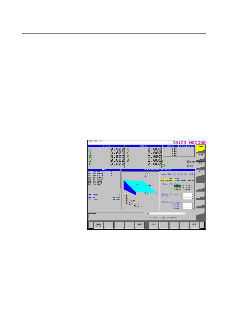
G68.2 / G68.4(Roll-Pitch-Yaw angle) 


Fig. 12.2.18.3 (b) Tilted working plane data setting screen- 
Roll-Pitch-Yaw angle(15-inch) 


 Multi 

Type 

Absolute: 
 

It is assumed that values of specified data are in a workpiece 
coordinate system, regardless of whether tilted working 
plane command mode is set. 

Incremental: 
 

It is assumed that values of specified data are in a feature 
coordinate system if tilted working plane command mode is 
already set. 


B-63944EN/03

 OPERATION 

12.SETTING AND DISPLAYING DATA


- 1565 - 


Order of Rotation 


Select an order in which the X-axis, Y-axis, and Z-axis are 
rotated in a workpiece coordinate system (for the absolute type) 
or the current feature coordinate system (for the incremental 
type). The selectable rotation orders are as follows: 


 1st 

rotation 
axis 

2nd rotation 

axis 

3rd rotation axis

X

Y

X-axis Y-axis  Z-axis 

X

Z

X-axis Z-axis  Y-axis 

Y

X

Y-axis X-axis  Z-axis 

Y

Z

Y-axis Z-axis  X-axis 

Z

X

Z-axis X-axis  Y-axis 

Z

Y

Z-axis Y-axis  X-axis 


Origin of Feature Coordinate 


Specify the origin (X, Y, and Z of point P) of a feature 
coordinate system as coordinates in a workpiece coordinate 
system (for the absolute type) or the current feature coordinate 
system (for the incremental type). 


Rotation Angle about X-axis 


Specify an angle of rotation around the X-axis of a workpiece 
coordinate system (for the absolute type) or the current feature 
coordinate system (for the incremental type). 


Rotation Angle about Y-axis 


Specify an angle of rotation around the Y-axis of a workpiece 
coordinate system (for the absolute type) or the current feature 
coordinate system (for the incremental type). 


Rotation Angle about Z-axis 


Specify an angle of rotation around the Z-axis of a workpiece 
coordinate system (for the absolute type) or the current feature 
coordinate system (for the incremental type). 


12.SETTING AND DISPLAYING DATA

 OPERATION 

B-63944EN/03


- 1566 - 

G68.2 / G68.4(3 points specification) 


Fig. 12.2.18.3 (c) Tilted working plane data setting screen- 3 points 

specification(15-inch) 


 Multi 

Type 

Absolute: 
 

It is assumed that values of specified data are in a workpiece 
coordinate system, regardless of whether tilted working 
plane command mode is set. 

Incremental: 
 

It is assumed that values of specified data are in a feature 
coordinate system if tilted working plane command mode is 
already set. 


B-63944EN/03

 OPERATION 

12.SETTING AND DISPLAYING DATA


- 1567 - 


Shift of the Origin 


Specify, in a feature coordinate system, an amount of shift from 
the feature coordinate system origin specified for the 1st point 
(point P1). 


Rotation Angle about the Z-axis in F-Coordinate 


Specify an angle of rotation around the Z-axis of a feature 
coordinate system. The direction of rotation angle R is positive 
when a rotation is made clockwise as viewed in the Z-axis 
direction of the feature coordinate system. 


1st point (Origin of Feature Coordinate) 


Specify the origin (X, Y, and Z of point P1) of a feature 
coordinate system as coordinates in a workpiece coordinate 
system (for the absolute type) or the current feature coordinate 
system (for the incremental type). 


 2nd 

point 


Specify the coordinates (X, Y, and Z of point P2) of the 2nd 
point as coordinates in a workpiece coordinate system (for the 
absolute type) or the current feature coordinate system (for the 
incremental type). The 1st point and 2nd point determine the 
X-axis of the feature coordinate system. 


 3rd 

point 


Specify the coordinates (X, Y, and Z of point P3) of the 3rd point 
as coordinates in a workpiece coordinate system (for the absolute 
type) or the current feature coordinate system (for the 
incremental type). Among the directions normal to the X-axis, a 
direction with a smaller angle relative to the P1 

 P3 vector is 

the Y-axis of the feature coordinate system. 


G68.2 / G68.4(2 vectors specification) 


Fig. 12.2.18.3 (d) Tilted working plane data setting screen-2 vectors 

specification(15-inch) 

12.SETTING AND DISPLAYING DATA

 OPERATION 

B-63944EN/03


- 1568 - 


 Multi 

Type 

Absolute: 
 

It is assumed that values of specified data are in a workpiece 
coordinate system, regardless of whether tilted working 
plane command mode is set. 

Incremental: 
 

It is assumed that values of specified data are in a feature 
coordinate system if tilted working plane command mode is 
already set. 


Origin of Feature Coordinate 


Specify the origin (X, Y, and Z of point P) of a feature 
coordinate system as coordinates in a workpiece coordinate 
system (for the absolute type) or the current feature coordinate 
system (for the incremental type). 


V1 (X’) vector 


Specify the X-axis direction vector of a feature coordinate 
system as values in a workpiece coordinate system (for the 
absolute type) or the current feature coordinate system (for the 
incremental type). 


V2 (Z’) vector 


Specify the Z-axis direction vector of a feature coordinate system 
as values in a workpiece coordinate system (for the absolute 
type) or the current feature coordinate system (for the 
incremental type). 


G68.2 / G68.4(Projection angle) 


Fig. 12.2.18.3 (e) Tilted working plane data setting screen-Projection 

angle(15-inch) 


B-63944EN/03

 OPERATION 

12.SETTING AND DISPLAYING DATA


- 1569 - 

 Multi 

Type 

Absolute: 
 

It is assumed that values of specified data are in a workpiece 
coordinate system, regardless of whether tilted working 
plane command mode is set. 

Incremental: 
 

It is assumed that values of specified data are in a feature 
coordinate system if tilted working plane command mode is 
already set. 


Origin of Feature Coordinate 


Specify the origin (X, Y, and Z of point P) of a feature 
coordinate system as coordinates in a workpiece coordinate 
system (for the absolute type) or the current feature coordinate 
system (for the incremental type). 


 Projection 

angle 

I  : Specify a projection angle relative to the X-axis of a 

workpiece coordinate system (for the absolute type) or the 
current feature coordinate system (for the incremental type). 

J  : Specify a projection angle relative to the Y-axis of a 

workpiece coordinate system (for the absolute type) or the 
current feature coordinate system (for the incremental type). 

K :  Specify an angle of rotation around the Z-axis of a feature 

coordinate system. 


G68.3(Tool Axis Direction) 


Fig. 12.2.18.3 (f) Tilted working plane data setting screen-Tool Axis 

Direction(15-inch) 

(When "No" is selected in "Origin command of Feature Coordinate") 


12.SETTING AND DISPLAYING DATA

 OPERATION 

B-63944EN/03


- 1570 - 


Fig. 12.2.18.3 (g) Tilted working plane data setting screen-Tool Axis 

Direction(15-inch) 

(When "Yes" is selected in "Origin command of Feature Coordinate") 


Origin command of Feature Coordinate 


Select whether to specify a feature coordinate system origin. 
Yes 

:  A feature coordinate system origin is specified. 

No 

:  A feature coordinate system origin is not specified. 


Origin of Feature Coordinate 


Specify the origin (X, Y, and Z of point P) of a feature 
coordinate system as coordinates in a workpiece coordinate 
system. 


This setting cannot be made if "No" is selected in "Origin 
command of Feature Coordinate". 


Rotation Angle about the Z-axis in F-Coordinate 


Specify an angle of rotation around the Z-axis of a feature 
coordinate system. The direction of rotation angle R is positive 
when a rotation is made clockwise as viewed in the Z-axis 
direction of the feature coordinate system. 


12.2.18.4 

Limitation 

 
This function is supported on 10.4-inch and 15-inch display units. 
This function is not displayed on 7.2-inch and 8.4-inch display units. 
 

B-63944EN/03

 OPERATION 

12.SETTING AND DISPLAYING DATA


- 1571 - 

12.3 

SCREENS DISPLAYED BY FUNCTION KEY 


Section 12.3, “SCREENS DISPLAYED BY FUNCTION KEY 

”, consists of the following subsections: 

―――――

  Screens of a 7.2/8.4/10.4-inch display unit 

12.3.1  Displaying and Entering Setting Data................................1573 
12.3.2  Sequence Number Comparison and Stop...........................1576 
12.3.3  Displaying and Setting Run Time, Parts Count, and Time 1578 
12.3.4  Displaying and Setting the Workpiece Origin Offset   

Value ..................................................................................1581 

12.3.5  Direct Input of Workpiece Origin Offset Value Measured 1582 
12.3.6  Displaying and Setting Custom Macro Common   

Variables ............................................................................1584 

12.3.7  Displaying and Setting Real Time Custom Macro Data ....1586 
12.3.8  Displaying and Setting the Software Operator’s Panel......1588 
12.3.9  Setting and Displaying Tool Management Data ................1591 
12.3.10 Displaying and Switching the Display Language ..............1612 
12.3.11 Protection of Data at Eight Levels .....................................1614 
12.3.12 Precision Level Selection...................................................1623 
12.3.13 Displaying and Setting Tool Life Management Data ........1625 
12.3.14 Displaying and Setting Workpiece Setting Error 

Compensation Data ............................................................1640 

12.3.15 Displaying and Setting Pattern Data Inputs .......................1642 
 

―――――

  Screens of a 15-inch display unit   

12.3.16 Displaying and Entering Setting Data   

(15-inch Display Unit) .......................................................1645 

12.3.17 Sequence Number Comparison and Stop   

(15-inch Display Unit) .......................................................1648 

12.3.18 Displaying and Setting Run Time, Parts Count, and Time 

(15-inch Display Unit) .......................................................1650 

12.3.19 Displaying and Setting the Workpiece Origin Offset   

Value (15-inch Display Unit).............................................1653 

12.3.20 Direct Input of Workpiece Origin Offset Value Measured 

(15-inch Display Unit) .......................................................1655 

12.3.21 Displaying and Setting Custom Macro Common   

Variables (15-inch Display Unit).......................................1657 

12.3.22 Displaying and Setting Real Time Custom Macro Data 

(15-inch Display Unit) .......................................................1659 

12.3.23 Displaying and Setting the Software Operator’s Panel 

(15-inch Display Unit) .......................................................1662 

12.3.24 Setting and Displaying Tool Management Data   

(15-inch Display Unit) .......................................................1665 

12.3.25 Displaying and Switching the Display Language   

(15-inch Display Unit) .......................................................1688 

12.3.26 Protection of Data at Eight Levels (15-inch Display Unit) 1690 
12.3.27 Precision Level Selection (15-inch Display Unit) .............1699 
12.3.28 Displaying and Setting Tool Life Management Data   

(15-inch Display Unit) .......................................................1701 


Content      ..     199      200      201      202     ..