FANUC Series 30i/300i/300is-MODEL A. Machining Center System. User's manual - page 199
 

  Index      Manuals     FANUC Series 30i/300i/300is-MODEL A. Machining Center System. User's manual (B-63944EN/03)


Search            copyright infringement  


Content      ..     197      198      199      200     ..


FANUC Series 30i/300i/300is-MODEL A. Machining Center System. User's manual - page 199


12.SETTING AND DISPLAYING DATA

 OPERATION 

B-63944EN/03


- 1548 - 

2  When two or more machining times are stamped 

The first machining time is displayed. 


Fig. 12.2.17 (g) When two or more machining times are stamped 

(15-inch) 


B-63944EN/03

 OPERATION 

12.SETTING AND DISPLAYING DATA


- 1549 - 

3  When the format of an inserted machining time is not 

“hhhHmmMssS” (H following a 3-digit number, M following a 
2-digit number, and S following a 2-digit number, in this order) 
The machining time display field is left blank. 


Fig. 12.2.17 (h) When the format of an inserted machining time is not 

“hhhHmmMssS” (H following a 3-digit number, M following a 2-digit 

number, and S following a 2-digit number, in this order) (15-inch) 


12.SETTING AND DISPLAYING DATA

 OPERATION 

B-63944EN/03


- 1550 - 

12.2.18 

Screen for Assistance in Entering Tilted Working Plane 

Command (15-inch Display Unit) 

 
The screens for assistance in entering tilted working plane commands 
(hereinafter referred to as guidance screens) include a command type 
selection screen and a tilted working plane data setting screen. The 
command type selection screen is used to select a tilted working plane 
command. The tilted working plane data setting screen is used to set 
specified tilted working plane data required for the selected command. 
By making settings and performing operations on these guidance 
screens, a tilted working plane command block can be created. 
The created block is reflected as a new insertion to a program being 
edited or as a modification to an existing block. 
This function can be enabled by setting bit 1 (GGD) of parameter No. 
11304 to 1. 
 

Creation of a new block 

The following describes the procedure for creating a tilted working 
plane command block on guidance screens and for inserting the block 
to a program being edited on a program editing screen. 
 

On a program editing screen, display a program to which you 
want to insert a tilted working plane command block. 


The foreground editing screen, background editing screen, or 
MDI editing screen should be displayed. 


Displaying the foreground editing screen 
<1>  Select the EDIT mode. 
<2>  Press function key 

<3>  Press vertical soft key [PROGRAM].   


Displaying the background editing screen 
<1>  Press function key 

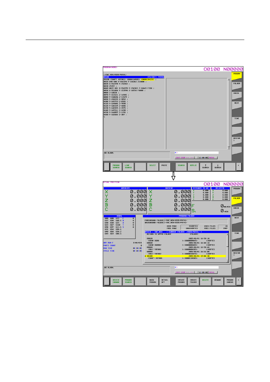
<2>  Press soft key [FOLDER].   
<3> Press any of the cursor keys to move the cursor to a 

program to be edited in the background. 

<4> Press 

 key. 


Displaying the MDI editing screen 
<1>  Select the MDI mode. 
<2>  Press function key 

<3>  Press vertical soft key [PROGRAM].   


B-63944EN/03

 OPERATION 

12.SETTING AND DISPLAYING DATA


- 1551 - 

The program editing screen is displayed. 


Press any of the cursor keys to move the cursor to a position 
where you want to insert a block. 


Note that a block created on the guidance screens is inserted after 
the block at the cursor position. (If the block at the cursor 
position includes a tilted working plane command, the existing 
block is modified. See "Modification to an existing block" 
below.) 

Press continuous menu key 

 several times, and then press 

horizontal soft key [GUIDANCE TWP]. 
The command type selection screen is displayed. 


12.SETTING AND DISPLAYING DATA

 OPERATION 

B-63944EN/03


- 1552 - 

Select a command type with any of the cursor keys, and then 
press horizontal soft key [SELECT]. 
The tilted working plane data setting screen is displayed. 


Enter command data for the setting items. 

Press horizontal soft key [INSERT].   


Press horizontal soft key [YES].   


This takes you back to the program editing screen, where the new 
block is inserted after the block at the cursor position. 


B-63944EN/03

 OPERATION 

12.SETTING AND DISPLAYING DATA


- 1553 - 

Modification to an existing block 

The following describes the procedure for replacing a block in a 
program being edited on a program editing screen, with a tilted 
working plane command block created on a guidance screen. 
 

On a program editing screen, display a program to be edited. 


(For the procedure for displaying a program editing screen, see 
step 1 in "Creation of a new block".) 


The program editing screen is displayed. 


Press any of the cursor keys to move the cursor to a block to be 
modified. 


For a command extending over more than one block, move the 
cursor to the first block. 

12.SETTING AND DISPLAYING DATA

 OPERATION 

B-63944EN/03


- 1554 - 

Press continuous menu key 

 several times, and then press 

horizontal soft key [GUIDANCE TWP]. The tilted working 
plane data setting screen is displayed. 


Enter command data for setting items to be modified. 

Press horizontal soft key [ALTER].   


Press horizontal soft key [YES].   
This takes you back to the program editing screen, where the 
block at the cursor position is replaced. 


B-63944EN/03

 OPERATION 

12.SETTING AND DISPLAYING DATA


- 1555 - 

Guidance screen cancellation 

Pressing horizontal soft key [CANCEL] on a guidance screen takes 
you back to the program editing screen. At this time, the data that has 
been set on the guidance screen is discarded. 
 

NOTE 

1


In addition to the above operation, the following 
operations also cancel a guidance screen. The 
data that has been set on the guidance screen is 
discarded. 


When bit 7 (CPG) of parameter No. 11302 is 1 
(setting for automatically switching between 
program-related screens according to CNC 
mode), the CNC mode is changed. 


When a guidance screen is displayed from the 
foreground editing screen, the CNC mode is 
changed to a mode other than EDIT, TJOG, or 
THND. 


When a guidance screen is displayed from the 
MDI editing screen, the CNC mode is changed 
to a mode other than MDI. 


When a guidance screen is displayed on a 
15-inch display unit, the screen is switched by 
a vertical soft key. 

  The s

creen is switched by an MDI key. 

  The s

creen is switched by a path select signal. 


An event that causes screen switching has 
occurred, including occurrence of an alarm, 
display of an operator message, or 
signal-based display of a screen (such as a 
tool compensation screen, workpiece shift 
screen, workpiece coordinate system setting 
screen, or C language executor screen). 

2  If MDI key 

  is pressed after switching from a 

guidance screen to another screen, a program 
editing screen is displayed, instead of the guidance 
screen. 


Notes 


Conditions under which horizontal soft key [GUIDANCE TWP] 
is displayed 


Horizontal soft key [GUIDANCE TWP] is displayed on a 
program editing screen under the following conditions: 

Foreground editing screen 

The CNC mode is EDIT, TJOG, or THND. 

-  The editing and display are not prohibited for a 

program to be edited. 


Content      ..     197      198      199      200     ..