FANUC Series 30i/300i/300is-MODEL A. Machining Center System. User's manual - page 155
 

  Index      Manuals     FANUC Series 30i/300i/300is-MODEL A. Machining Center System. User's manual (B-63944EN/03)


Search            copyright infringement  


Content      ..     153      154      155      156     ..


FANUC Series 30i/300i/300is-MODEL A. Machining Center System. User's manual - page 155


6.SAFETY FUNCTIONS

 OPERATION 

B-63944EN/03


- 1196 - 


For machining center system 


a

The position of the 
tool after reference


position return 

Area boundary

A

B


For lathe system 

The position of the
tool after reference

position return

Forbitten area boundary

b

a

B

A


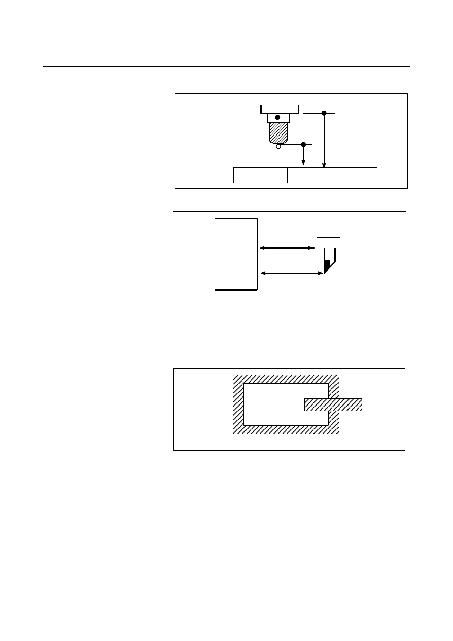
Fig. 6.3 (d)    Setting the forbidden area 


  - Forbidden area overlapping


Area can be set in piles. 
 

Setting the forbidden area overlapping


Fig. 6.3 (e)    Setting the forbidden area overlapping 

 
Unnecessary limits should be set beyond the machine stroke. 
 

  - Condition under which each check is enabled   

Each check becomes effective after the power is turned on and manual 
reference position return or automatic reference position return by 
G28 has been performed. 
After the power is turned on, if the reference position is in the 
forbidden area of each limit, an alarm is generated immediately.  
(Only in G22 mode for stored stroke check 2). 
 

B-63944EN/03

 OPERATION 

6.SAFETY FUNCTIONS


- 1197 - 

  - Releasing the alarms 

If the enters a forbidden area and an alarm is generated, the tool can be 
moved only in the backward direction.  To cancel the alarm, move 
the tool backward until it is outside the forbidden area and reset the 
system.  When the alarm is canceled, the tool can be moved both 
backward and forward. 
 

  - Change from G23 to G22 in a forbidden area 

When G23 is switched to G22 in the forbidden area, the following 
results. 
<1> When the forbidden area is inside, an alarm is informed in the 

next move. 

<2> When the forbidden area is outside, an alarm is informed 

immediately.  


  - Timing for displaying an alarm 

 
In stored stroke check 1/2/3, parameter BFA (bit 7 of No. 1300) 
selects whether an alarm is displayed immediately before the tool 
enters the forbidden area or immediately after the tool has entered the 
forbidden area. 
 

Alarm 

Number

Message Description 

OT0500 + OVERTRAVEL (SOFT 1)

A movement in the positive direction 
exceeded stored stroke check 1. 

OT0501 - OVERTRAVEL (SOFT 1)

A movement in the negative direction 
exceeded stored stroke check 1. 

OT0502 + OVERTRAVEL (SOFT 2)

A movement in the positive direction 
exceeded stored stroke check 2. 

OT0503 - OVERTRAVEL (SOFT 2)

A movement in the negative direction 
exceeded stored stroke check 2. 

OT0504 + OVERTRAVEL (SOFT 3)

A movement in the positive direction 
exceeded stored stroke check 3. 

OT0505 - OVERTRAVEL (SOFT 3)

A movement in the negative direction 
exceeded stored stroke check 3. 


6.SAFETY FUNCTIONS

 OPERATION 

B-63944EN/03


- 1198 - 

6.4 

STROKE LIMIT CHECK BEFORE MOVE 

 
During automatic operation, before the movement specified by a given 
block is started, whether the tool enters the forbidden area defined by 
stored stroke check 1, 2, or 3 is checked by determining the position 
of the end point from the current position of the machine and a 
specified amount of travel. If the tool is found to enter the forbidden 
area defined by a stored stroke limit, the tool is stopped immediately 
upon the start of movement for that block, and an alarm is displayed. 
 

 WARNING 


Whether the coordinates of the end point, reached 
as a result of traversing the distance specified in 
each block, are in a forbidden area is checked. In 
this case, the path followed by a move command is 
not checked. However, if the tool enters the 
forbidden area defined by stored stroke check 1, 2, 
or 3, an alarm is issued. (See the examples below.) 


Example 1)

The tool is stopped at point a according to stored stroke 

check 1 or 2. 

Immediately upon movement commencing from the start 

point, the tool is stopped to enable a stroke limit check 

before moving to be performed before movement. 

Forbidden area defined by stored stroke 

check 1 or 2 


Start point

a

Forbidden area defined by stored stroke 

check 1 or 2 

End point 

End point 


B-63944EN/03

 OPERATION 

6.SAFETY FUNCTIONS


- 1199 - 


Example 2)

End 

point 

End point

Start point

Immediately upon movement commencing from the start 

point, the tool is stopped to enable a stroke limit check 

before moving to be performed before movement. 

The tool is stopped at point a according to stored 

stroke check 2 or 3. 

Forbidden area defined by stored stroke 

check 2 or 3 

Forbidden area defined by stored stroke 

check 2 or 3 

a


Explanation 

When a stroke limit check before moving is performed, whether to 
check the movement performed by a G31 (skip) block and G37 
(automatic tool length measurement) block can be determined using  
(parameter NPC (No. 1301#2)). 
 

Limitation 
 - Machine lock 

If machine lock is applied at the start of movement, no stroke limit 
check made before movement is performed. 
 

 - G23 

When stored stroke check 2 is disabled (G23 mode), no check is made 
to determine whether the tool enters the forbidden area defined by 
stored stroke check 2. 
 

 - Program restart 

When a program is restarted, an alarm is issued if the restart position 
is within a forbidden area. 
 

  - Manual intervention following a feed hold stop 

When the execution of a block is restarted after manual intervention 
following a feed hold stop, no alarm is issued even if the end point 
following a manual intervention is within a forbidden area. 
 

6.SAFETY FUNCTIONS

 OPERATION 

B-63944EN/03


- 1200 - 

  - A block consisting of multiple operations 

If a block consisting of multiple operations (such as a canned cycle 
and exponential interpolation) is executed, an alarm is issued at the 
start point of any operation whose end point falls within a inhibited 
area. 
 

  - Cylindrical interpolation mode 

In cylindrical interpolation mode, no check is made. 
 

  - Polar coordinate interpolation mode 

In polar coordinate interpolation mode, no check is made. 
 

  - Three-dimensional coordinate system conversion 

In three-dimensional coordinate system conversion mode, no check is 
made. 
 

  - PMC axis control 

No check is made for a movement based on PMC axis control. 
 

Alarm 

Table 6.4 (a)    Alarm 

Number

Message Description 

OT0510

+ OVERTRAVEL 
( PRE-CHECK ) 

The block end point was found in the + side 
stroke limit prohibition area during a stroke 
check before movement. 
Modify the program. 

OT0511

- OVERTRAVEL 
( PRE-CHECK ) 

The block end point was found in the - side 
stroke limit prohibition area during a stroke 
check before movement. 
Modify the program. 


B-63944EN/03

 OPERATION 

6.SAFETY FUNCTIONS


- 1201 - 

6.5 

WRONG OPERATION PREVENTION FUNCTIONS 

 
An improper tool offset setting or an improper operation of the 
machine can result in the workpiece being cut inadequately or the tool 
being damaged.    Also, if data is lost due to an operation mistake, it 
takes extra time to recover from the mistake. 
The operation confirmation functions described below are meant to 
prevent the operator from performing any unintended operation 
(hereinafter referred to as an improper operation). 

Functions that are used when data is set 


Data check to verify that the offset data is within the valid 
setting range 


Incremental input operation confirmation 


Prohibition of the absolute input by the soft key to prevent 
any improper absolute or incremental input operation 


Confirmation of any operation of deleting the program or all 
data 

  Confirmation of a data update during the data setting 

process 

Functions that are used when the program is executed 


Highlighting of updated modal information 


Display of the executed block status prior to the program 
execution 


Display of the axis status, such as the mirror image function 
enabled or the interlock function enabled 


Check for starting from the middle of the program 

  Data check to verify that the offset data is within the 

effective setting range 


Maximum incremental value check 


6.SAFETY FUNCTIONS

 OPERATION 

B-63944EN/03


- 1202 - 

6.5.1 

Functions that are Used When Data is Set 

 
The following functions are provided to prevent improper operations 
when data is set. 


Input data range check 


Confirmation of incremental input 


Prohibition of the absolute input by the soft key 


Confirmation of the deletion of the program 


Confirmation of the deletion of all data 


Confirmation of a data update during the data setting process 

 
Set these functions on the operation confirmation function setting 
screen.    For the input data range check, set a valid input data range, 
e.g. the upper and lower limits, for each input screen.    For the other 
functions, specify whether to enable or disable them. 
For information about how to display the individual setting screens, 
how to manipulate them, and other details, see the item “Operation 
confirmation setting screen” that describes the operation procedures. 
 

B-63944EN/03

 OPERATION 

6.SAFETY FUNCTIONS


- 1203 - 

6.5.1.1 

Input data range check 

 
This function allows an effective data range to be set and checks 
whether the input data is within the set range. 
 

Input data range check 

Explanation 

  - Outline of the input data range check 

This function allows an effective data range to be set for the data of 
each input screen listed later and checks whether the input data is 
within the set range.  If the input data is out of the effective data 
range, the warning message "DATA IS OUT OF RANGE" is 
displayed and the data is rejected. 
 
For example, assume that the effective data range for a certain tool 
offset number is set to -200. to 200, and that you are going to input 
100.[INPUT].  Even if you inadvertently press the 0 key one more 
time, resulting in 1000.[INPUT], the input of 1000. is not accepted. 
The function detects a setting mistake and prevents the program from 
running with invalid data. 
 

  - Input screens for which this function is effective 

 Tool 

compensation 


Workpiece origin offset 

T


Y-axis tool offset 

 Workpiece 

shift 


 - Settings 

To enable this function, set an effective data range for each input 
screen on the operation confirmation function setting screen.  For 
information about how to display the individual setting screens, how 
to set data ranges, and other details, see the items that describe the 
setting of the data ranges. 
If the set data range is invalid, no data input is accepted.    Correct the 
data range setting, and then input data. 
 

  - Disabling the function 

The input data range check is disabled if you make any of the 
following settings on the operation confirmation function setting 
screen. 


Both the upper and lower limit values for the tool offset number 
or workpiece coordinate system are 0. 


The upper and lower limit values for each offset are identical. 


Content      ..     153      154      155      156     ..