FANUC Series 30i/300i/300is-MODEL A. Machining Center System. User's manual - page 150
 

  Index      Manuals     FANUC Series 30i/300i/300is-MODEL A. Machining Center System. User's manual (B-63944EN/03)


Search            copyright infringement  


Content      ..     148      149      150      151     ..


FANUC Series 30i/300i/300is-MODEL A. Machining Center System. User's manual - page 150


4.AUTOMATIC OPERATION

 OPERATION 

B-63944EN/03


- 1156 - 

4.9.5 

Tool Retract and Recover for Threading 


Explanation 
  - Differences between ordinary tool retract and recover and tool retract and recover 

for threading 

During retraction, chamfering is performed between the specified 
retraction axis and threading axis. 

2  After retraction, one block that does not specify threading is 

executed and the tool stops. 

When the major axis for threading is specified as the retraction 
axis, retraction is not performed by turning the TOOL 
WITHDRAW switch on.  In this case, after a block that does 
not specify threading is executed, an alarm PS0429 is issued and 
the tool stops. 

As repositioning, the tool is returned to the position specified in 
the first block that does not specify threading. 


 - Operation procedure 

1  Specify a retraction axis and retraction distance in command 

“G10.6IP- -;”. 

O1234 
G90G0X0Z0 ; 
S150 M03 ; 
N10 G91 G00 X-50. ; 
N20 G10.6 X40.0 ; 
N30 G33 Z-100. F2.0 ; 
N40 G00 X50. ; 
N50 Z100. ; 
M02; 
 
Retraction axis:  X 
Retraction distance:  40.0 

N10

N30

N50

N40

b

a

d

c

Threading

X


Z


Turn the TOOL WITHDRAW switch during the execution of a 
threading command block. 

3  The tool withdrawal mode is set and retraction is performed.  

Chamfering at 45 degrees is performed between the retraction 
axis and major axis for threading using the retraction distance as 
the chamfering amount during retraction. 
Details of retraction differ depending on whether the remaining 
travel distance for the threading command is smaller than the 
retraction distance when the TOOL WITHDRAW switch is 
turned on as follows: 
 

B-63944EN/03

 OPERATION 

4.AUTOMATIC OPERATION


- 1157 - 

(1)  When remaining travel distance for threading 

 retraction 

distance


45

°


A

Retraction position

Retraction 
distance 


When the position where 45-degree chamfering by the 
retraction distance ends does not exceed the threading end 
position (c), the tool moves to the threading end position 
after the termination of chamfering. 


(2) When the remaining travel distance for threading < 

retraction distance 

d

c

A

Retraction position 

Retraction distance


When the position where 45-degree chamfering by the 
retraction distance ends exceeds the threading end position 
(c), the tool moves to the retraction position along the 
retraction axis after it reaches the threading end position. 


4.AUTOMATIC OPERATION

 OPERATION 

B-63944EN/03


- 1158 - 

After retraction is completed, the next block that does not specify 
threading is executed and the tool stops. 

Retraction position

Point E


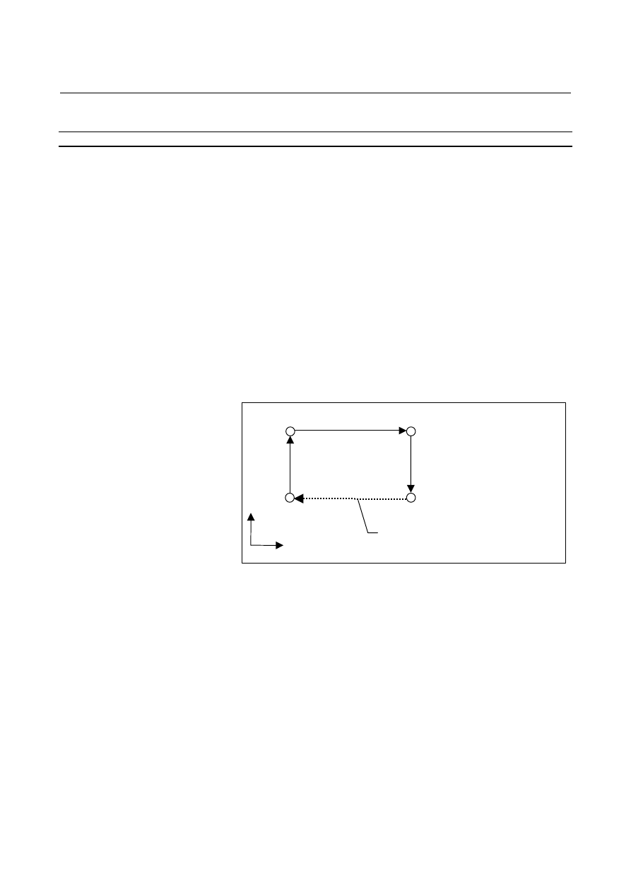
In this example, “X50.0” is specified in the first block that does 
not specify threading in the incremental mode, the tool moves to 
point E and stops. 


If the major axis for threading is specified as the retraction axis, 
the block that does not specify threading is executed without 
performing retraction, an alarm PS0429 is issued, and the tool 
stops. 


As repositioning, the tool returns to the position specified in the 
first block that does not specify threading. 

Retraction position

Point E

Repositioning 

N50


In this example, the repositioning position is point d.  
Automatic operation after repositioning starts at the N50 block. 


B-63944EN/03

 OPERATION 

4.AUTOMATIC OPERATION


- 1159 - 

4.9.6 

Operation Procedure for a Canned Cycle for Drilling 


Explanation 
 - Retract 

When the TOOL WITHDRAW switch is turned on during a canned 
cycle for drilling (abbreviated as a canned cycle below), retraction is 
performed depending on the cycle operation being executed at that 
time. 


Operation 1:    Positioning to a hole position 

Operation 2:    Rapid traverse to point R 

Operation 3:  Hole machining 

Operation 4:    Operation at the bottom of the hole

Operation 5:  Retraction to point R 

Operation 6:    Rapid traverse to the initial point


Initial point 

Point R

Operation 1

Operation 2

Operation 6

Operation 3

Operation 5

Operation 4


1  During operation 1, the tool moves by the retraction distance 

specified in G10.6 in the same way as for ordinary retraction. 

2  During operation 2, the tool stops operation 2, moves to the 

initial point, and stops. 

During operation 3, the tool stops operation 3, executes cycle 
operations 4, 5, and 6 from that position, and stops at the initial 
point. 

During operation 4, 5, or 6, the tool continues the operation and 
stops at the initial point. 
When the TOOL WITHDRAW switch is turned on during 
operation 2 to 6, the tool does not move according to the 
retraction specified in G10.6.  After the TOOL WITHDRAW 
switch is turned on and the tool moves to the initial point, 
however, the tool withdrawal mode is set. 
When the second or subsequent canned cycle is being executed 
and the TOOL WITHDRAW switch is turned on during 
operation 2 to 6, the retraction position differs depending on G98 
(return to initial level) or G99 (return to point R level). 


G98 (return to initial level): The tool moves to the initial 
level. 


G99 (return to point R level):The tool moves to the point R 
level. 

During operation 2 to 6, the tool also moves to the initial point 
and stops when the TOOL WITHDRAW switch is turned on 
without the G10.6 command specified. 


4.AUTOMATIC OPERATION

 OPERATION 

B-63944EN/03


- 1160 - 

 - Repositioning 

When the tool is at the retraction position and the cycle start switch is 
pressed, repositioning is performed for the canned cycle. 

Repositioning performed when the TOOL WITHDRAW switch 
is turned on during operation 1 
After the completion of repositioning, automatic operation is 
resumed in the same way as for ordinary repositioning. 

Repositioning performed when the TOOL WITHDRAW switch 
is turned on during operation 2 
The canned cycle is reexecuted from operation 2. 

Repositioning performed when the TOOL WITHDRAW switch 
is turned on during operation 3 
The canned cycle is reexecuted from operation 2. 

Repositioning performed when the TOOL WITHDRAW switch 
is turned on during operation 4, 5, or 6 
The canned cycle is reexecuted for the same hole position from 
operation 2. 


B-63944EN/03

 OPERATION 

4.AUTOMATIC OPERATION


- 1161 - 

4.10 

RETRACE 


M


Overview 

The tool can retrace the path along which the tool has moved so far 
(reverse execution).  Furthermore, the tool can move along the 
retraced path in the forward direction (forward reexecution). After 
forward reexecution is performed until the tool reaches the position 
at which reverse execution started, machining is continued as 
programmed. 
 

Procedure 
 - Forward execution 

 reverse execution 

To perform forward execution of a program, set the “REVERSE” 
switch on the machine operator’s panel to off, then perform a cycle 
start operation.    If the “REVERSE” switch on the machine operator’s 
panel is set to on, reverse execution or the end of reverse execution 
results. 
To perform reverse execution of a program, use one of the following 
three methods: 
1)  Set the “REVERSE” switch on the machine operator’s panel to 

on during forward execution of a block. 

2)  Perform a single block stop operation during forward execution, 

then set the “REVERSE” switch on the machine operator’s panel 
to on. 

3)  Perform a feed hold stop operation during forward execution, 

then set the “REVERSE” switch on the machine operator’s panel 
to on. 

 
When method 1) is used, reverse execution starts after the end of the 
block being executed (after execution up to the single block stop 
position).  Reverse execution does not start as soon as the 
“REVERSE” switch on the machine operator’s panel is set to on. 


Fig. 4.10 (a)     

If functions for gas cutting machine are enabled, however, only when 
linear interpolation (G01), circular interpolation (G02, G03), or skip 
function (G31) is specified, reverse execution starts at the position at 
which the “REVERSE” switch is set to on. 

Forward
Reverse

"REVERSE" switch = ON 
 

Cycle start (start of forward execution)

Start of reverse execution

4.AUTOMATIC OPERATION

 OPERATION 

B-63944EN/03


- 1162 - 


Fig. 4.10 (b)     

When method 2) is used, performing a cycle start operation starts 
reverse execution from the position at which a single block stop takes 
place. 


Single block stop 
"REVERSE" switch = ON 
Cycle start 

Cycle start (start of forward execution)

Start of reverse execution

Forward
Reverse


Fig. 4.10 (c)     

 
When method 3) is used, performing a cycle start operation starts 
reverse execution from the position at which a feed hold stop takes 
place. 


Feed hold stop 
"REVERSE" switch = ON 
Cycle start 

Cycle start (start of forward execution)

Start of reverse execution

Forward
Reverse


Fig. 4.10 (d)     


 - Reverse execution 

 forward reexecution 

To perform forward reexecution of a program, use one of the 
following three methods: 

1)  Set the “REVERSE” switch on the machine operator’s 

panel to off during reverse execution of a block. 

2)  Set the “REVERSE” switch on the machine operator’s 

panel to off after a single block stop takes place during 
reverse execution. 

3)  Set the “REVERSE” switch on the machine operator’s 

panel to off after a feed hold stop takes place during reverse 
execution. 

 
When method 1) is used, forward reexecution starts after the block 
being executed ends (after execution up to the position at which a 
single block stop takes place).    Forward reexecution does not start as 
soon as the “REVERSE” switch on the machine operator’s panel is set 
to off. 


"REVERSE" switch = ON 

Cycle start (start of forward execution)

Start of reverse execution 

Forward
Reverse

B-63944EN/03

 OPERATION 

4.AUTOMATIC OPERATION


- 1163 - 


Cycle start (start of forward execution)

Start of forward         "REVERSE" switch = OFF 
reexecution 

Forward 
Reverse 
Forward 
reexecution

Start of reverse execution


Fig. 4.10 (e)     

 
If functions for gas cutting machine are enabled, however, only when 
linear interpolation (G01), circular interpolation (G02, G03), or skip 
function (G31) is specified, forward reexecution starts at the position 
at which the “REVERSE” switch is set to 0. 


Fig. 4.10 (f)     

 
When method 2) is used, performing a cycle start operation starts 
forward reexecution from the position at which a single block stop 
takes place. 

Cycle start (start of forward execution)


Start of forward reexecution
 

Forward 
Reverse 
Forward  
reexecution

Start of reverse execution

Restart of forward execution


Fig. 4.10 (g)     

 
When method 3) is used, performing a cycle start operation starts 
forward reexecution from the position at which a feed hold stop takes 
place. 


Feed hold stop 
"REVERSE" switch = OFF 
Cycle start 

Cycle start (start of forward execution)

Start of forward reexecution

Forward 
Reverse 
Forward 
reexecution

Start of reverse execution

Fig. 4.10 (h)     


"REVERSE" 
switch = OFF 

Cycle start (start of forward execution)

Start of forward reexecution 

Forward 
Reverse 
Forward 
reexecution

Start of reverse
execution 


Content      ..     148      149      150      151     ..