FANUC Series 30i/300i/300is-MODEL A. Machining Center System. User's manual - page 148
 

  Index      Manuals     FANUC Series 30i/300i/300is-MODEL A. Machining Center System. User's manual (B-63944EN/03)


Search            copyright infringement  


Content      ..     146      147      148      149     ..


FANUC Series 30i/300i/300is-MODEL A. Machining Center System. User's manual - page 148


4.AUTOMATIC OPERATION

 OPERATION 

B-63944EN/03


- 1140 - 

The block number is searched for, and the program restart screen 
appears on the LCD display. 


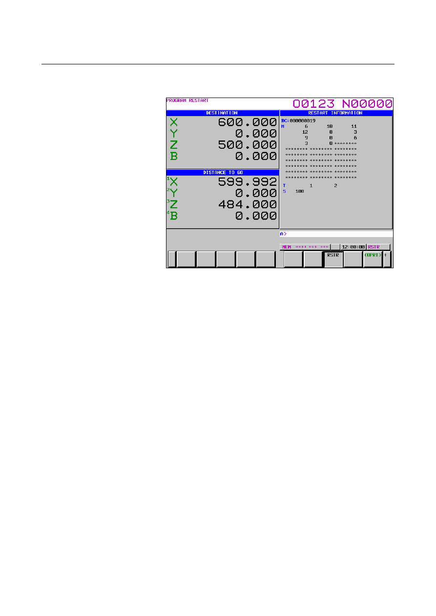
Fig. 4.8 (b)    Program restart screen 


DESTINATION shows the position at which machining is to 
restart. 


DISTANCE TO GO shows the distance from the current tool 
position to the position where machining is to restart.  A 
number to the left of each axis name indicates the order of axes 
(determined by parameter setting) along which the tool moves to 
the restart position. 


The coordinates and amount of travel for restarting the program 
can be displayed for up to four axes.    If your system supports 
five or more axes, pressing the [RSTR] soft key again displays 
the data for the fifth and subsequent axes.   
M :  Up to 35 most recently specified M codes.    The maximum 

number of displayed M codes differs depending on the size 
of the display. 
With 15-inch or 10.4-inch LCD/MDI panel : 
 

Up to 30 M codes 

With 9.5-inch LCD/MDI panel : Up to 6 M codes 

T  :  Two most recently specified T codes 
S  :  Most recently specified S code 
B  :  Most recently specified B code 
    Codes are displayed in the order in which they are specified.   

All codes are cleared by a program restart command or 
cycle start in the reset state. 

Turn the program re-start switch OFF.    At this time, the figure 
at the left side of axis name DISTANCE TO GO blinks. 

Check the screen for the M, S, T, and B codes to be executed.   
If they are found, enter the MDI mode, then execute the M, S, T, 
and B functions.  After execution, restore the previous mode.  
These codes are not displayed on the program restart screen. 

B-63944EN/03

 OPERATION 

4.AUTOMATIC OPERATION


- 1141 - 

Check that the distance indicated under DISTANCE TO GO is 
correct.  Also check whether there is the possibility that the tool 
might hit a workpiece or other objects when it moves to the 
machining restart position.    If such a possibility exists, move the 
tool manually to a position from which the tool can move to the 
machining restart position without encountering any obstacles. 

Press the cycle start button.    The tool moves to the machining 
restart position at the dry run feedrate sequentially along axes in 
the order specified by parameter No. 7310 settings.    Machining 
is then restarted. 


Outputting the M, S, T, and B codes for program restart 

 
After the block to be restarted is searched for, you can perform the 
following operations: 
 

Before the tool is moved to the machining restart position 
<1> The most recently specified M, S, T, and B codes can 

automatically be output to the PMC. 
The most recently specified S code is output as the 
maximum spindle speed when the S code is specified in the 
block containing G92 or as the specified spindle speed in 
other cases.  As the most recently specified S code, only 
one S code is displayed on the program restart screen 
regardless of whether the S code is specified in the block 
containing G92. 

<2> While the block to be restarted is being searched for, all 

sampled M codes and most recently specified S, T, and B 
codes can automatically be output to the PMC.    Up to 35 
M codes can be sampled.  If the number of sampled M 
codes exceeds 35, the 35 most recently specified M codes 
are output to the PMC. 


Switch between operations <1> and <2> using bit 6 (MOA) of 
parameter No. 7300. 

Before the tool reaches the machining restart position 


On the program restart screen, you can specify M, S, T, and B 
codes from the MDI panel in the MEM or RMT mode without 
changing the mode. 


Outputting the most recently specified M, S, T, and B codes 

 
When bit 7 (MOP) of parameter No. 7300 is set to 1, pressing the 
cycle start switch after searching for the block to be restarted 
automatically outputs the most recently specified M, S, T, and B codes 
to the PMC before the tool is moved to the machining restart position. 
In the single block stop status, after the most recently specified M, S, 
T, and B codes are output, pressing the cycle start switch again moves 
the tool to the machining restart position. 
 

4.AUTOMATIC OPERATION

 OPERATION 

B-63944EN/03


- 1142 - 

Outputting all M codes and most recently specified S, T, and B codes 

 
When bit 6 (MOA) of parameter No. 7300 is set to 1, pressing the 
cycle start switch after searching for the block to be restarted 
automatically outputs all M codes and most recently specified S, T, 
and B codes to the PMC before the tool is moved to the machining 
restart position. 
(Example) 
 

When M10, M11, M12, M13, M14, T0101, S1000, and B10 are 
sampled, a program is executed in the format shown below 
before the tool is moved to the machining restart position: 
M10 T0101 S1000 B10 ; 
M11 ; 
M12 ; 
M13 ; 
M14 ; 
 

Outputting M, S, T, and B codes on the program restart screen 

 
When bit 7 (MOP) of parameter No. 7300 is set to 1, you can specify 
M, S, T, and B codes from the MDI panel in the MEM or RMT mode 
without changing the mode after searching for the block to be 
restarted until the tool reaches the machining restart position. 
 

Procedure 

When the block to be restarted is searched for using the program 
restart function, the program restart screen appears.    When bit 7 
(MOP) of parameter No. 7300 is set to 1, operation soft keys 
[OVERSTORE], [ERASE], and [INPUT] are displayed. 


Fig. 4.8 (c)    Program restart screen (outputting M, S, T, and B codes) 


B-63944EN/03

 OPERATION 

4.AUTOMATIC OPERATION


- 1143 - 

Before the tool reaches the machining restart position, pressing 
soft key [OVERSTORE] selects the over store mode.  In the 
over store mode, data can be entered in the M, S, T, and B fields 
displayed in the (OVERSTORE) section. 
To select the over store mode while the tool is moving to the 
machining restart position, hold restart operation by feed hold 
and press soft key [OVERSTORE]. 
Enter M, S, T, and B codes to be output in the (OVERSTORE) 
section from the MDI panel. 
(Example) 
  To enter M10, S1000, T101, and B20 in the 

(OVERSTORE) section: 

<1> Enter 

M

1

0

  from the MDI panel. 

<2>  Press the [INPUT] key. 


You can also enter the S, T, and B codes by performing 
steps <1> and <2>. 


Fig. 4.8 (d)    Program restart screen when M, S, T, and B codes are 

output 


When values have been entered in the (OVERSTORE) section, 
pressing the cycle start switch outputs each code in the 
(OVERSTORE) section.  The values in the (OVERSTORE) 
section are cleared. 

To clear the values entered in the (OVERSTORE) section as M, 
S, T, and B codes, press soft key [ERASE].    All entered values 
are cleared. 

Pressing soft key [OVERSTORE] again in the over store mode 
cancels the mode.    Pressing the reset key also cancels the over 
store mode. 

To continue with restart operation, cancel the over store mode 
and press the cycle start switch. 


4.AUTOMATIC OPERATION

 OPERATION 

B-63944EN/03


- 1144 - 

 CAUTION 

1  The M, S, T, and B codes specified in the over store 

mode are not displayed on the program restart 
screen. 

2  In the over store mode, changing the operation 

mode to other than the MEM or RMT mode does not 
cancel the over store mode.    In this case, no 
values can be entered in the (OVERSTORE) 
section. 

3  In lathe systems, do not specify a T code in the over 

store mode.    If a T code is specified, it is not 
executed. 


Explanation 
 - Block number 

When the CNC is stopped, the number of executed blocks is displayed 
on the program screen or program restart screen.    The operator can 
specify the number of the block from which the program is to be 
restarted, by referencing the number displayed on the screen.  The 
displayed number indicates the number of the block that was executed 
most recently.    For example, to restart the program from the block at 
which execution stopped, specify the displayed number, plus one. 
The number of blocks is counted from the start of machining, 
assuming one NC line of a CNC program to be one block. 
 
(Example 1) 

CNC Program 

Number of blocks 


O 0001 ; 


G90 G92 X0 Y0 Z0 ; 


G01 X100. F100 ; 


G03 X01 -50. F50 ; 

 M30 


(Example 2) 

CNC Program 

Number of blocks 


O 0001 ; 


G90 G92 X0 Y0 Z0 ; 


G90 G00 Z100. ; 


G81 X100. Y0. Z120. R-80. F50. ; 

 #1=#1+1 

 #2=#2+1 

 #3=#3+1 


G00 X0 Z0 ; 

 M30 


Macro statements are not counted as blocks. 
 

  - Storing / clearing the block number 

The block number is held in memory while no power is supplied.  
The number can be cleared by cycle start in the reset state. 
 

B-63944EN/03

 OPERATION 

4.AUTOMATIC OPERATION


- 1145 - 

  - Block number when a program is halted or stopped 

The program screen usually displays the number of the block currently 
being executed.  When the execution of a block is completed, the 
CNC is reset, or the program is executed in single-block stop mode, 
the program screen displays the number of the program that was 
executed most recently.    When a CNC program is halted or stopped 
by feed hold, reset, or single-block stop, the following block numbers 
are displayed: 
 

Feed hold :    Block being executed 


Reset :    Block executed most recently 


Single-block stop :    Block executed most recently 

For example, when the CNC is reset during the execution of block 10, 
the displayed block number changes from 10 to 9. 
 

 - MDI intervention 

When MDI intervention is performed while the program is stopped by 
single-block stop, the CNC commands used for intervention are not 
counted as a block. 
 

  - Block number exceeding eight digits 

When the block number displayed on the program screen exceeds 
eight digits, the block number is reset to 0 and counting continues. 
 

Limitation 
  - P type Restart 

In the following conditions, P type restart cannot be performed: 


Automatic operation has not been performed since power-on. 


Automatic operation has not been performed since emergency 
stop was released. 


Automatic operation has not been performed since the coordinate 
system was changed or shifted (change of the external workpiece 
origin offset value).   

The block that can be restored properly by P type program restart is a 
block for which coordinate system setup or change was performed 
most recently before machining was interrupted. 
 

 - Restart block 

The block where the program is to restart is not necessarily be the 
block at which the program was interrupted.  You can restart the 
program from any block.  For P-type restart, however, the block 
where the program is to restart must use the same coordinate system as 
when program execution was interrupted. 
 

 - Single block 

When the single-block operation is enabled at the time of a movement 
to the restart point, a single-block stop occurs each time an axis 
operation takes place.    In this case, no MDI operation is allowed. 
 

4.AUTOMATIC OPERATION

 OPERATION 

B-63944EN/03


- 1146 - 

 - Manual intervention 

During movement to the restart point, manual intervention is allowed 
for an axis for which a return operation has not yet been performed.   
However, manual operations do not cause any movement along axes 
for which a return operation has already been completed. 
 

 - MDI 

When the search operation has ended, no move command can be 
specified by MDI before axis movement. 
 

 - Reset 

Do not perform a reset operation during the time from the start of the 
search operation of the restart sequence until machining is restarted. 
If a reset operation is performed, the restart steps must be performed 
again from the beginning. 
 

 - Feed hold 

If a feed hold operation is performed during the search, the restart 
steps must be performed again from the beginning. 
 

 - Manual absolute 

Every manual operation must be performed with the manual absolute 
mode turned on regardless of whether the manual operation is 
performed before or after machining. 
 

  - Reference position return 

Unless an absolute position detector (absolute pulse coder) is provided, 
be sure to perform reference position return after power-up, then 
perform restart operation. 
 

  - Program restart switch 

When the program restart switch is on, pressing the cycle start switch 
does not start operation. 
 

  - Blocks specifying a macro statement, macro call, and subprogram call 

Blocks specifying a macro statement, macro call, and subprogram call 
are not searched for even when they have a sequence number.  In 
such a case, search for a block previously preceding such a block. 
 

  - Interruption type custom macro 

During movement to the machining restart point at a dry run feedrate, 
no interruption type custom macro can be started.    If an interruption 
type custom macro is started, alarm DS024 is issued. 
 

B-63944EN/03

 OPERATION 

4.AUTOMATIC OPERATION


- 1147 - 

  - Commands that prevent program restart 

Program restart cannot be performed for blocks placed in the 
following modes: 


Cs contouring control 


Polygon turning (G50.2) 


Threading (G32,G33), Circular threading (G35,G36), Threading 
cycle (G92), Multiple repetitive threading cycle (G76) 


Polar coordinate interpolation (G12.1) 


Balance cutting (G68) 

 Rigid 

tapping 

If any of the following commands is included between the beginning 
of a program and the block where the program is to restart, program 
restart cannot be performed: 


Workpiece coordinate system preset (G92.1,G50.3) 

  Commands for enabling and disabling synchronous/composite 

control and superimposed control   


Commands for enabling and disabling axis synchronous control 


  - M, S, and T commands not usable in over store mode 

The M, S, and T functions listed below, unlike the other M, S, and T 
functions, have special meanings within the CNC.    These M, S, and 
T commands cannot be specified from the over store screen.  To 
specify these commands, cancel the over store mode, and execute 
them in MDI operation. 
Example: 

 Spindle 

positioning 

 Rigid 

tapping 

 Tool 

management 


Content      ..     146      147      148      149     ..